EP3637005B1 - Dispositif de ventilation à échange de chaleur - Google Patents
Dispositif de ventilation à échange de chaleur Download PDFInfo
- Publication number
- EP3637005B1 EP3637005B1 EP17912437.5A EP17912437A EP3637005B1 EP 3637005 B1 EP3637005 B1 EP 3637005B1 EP 17912437 A EP17912437 A EP 17912437A EP 3637005 B1 EP3637005 B1 EP 3637005B1
- Authority
- EP
- European Patent Office
- Prior art keywords
- heat exchanger
- heat exchange
- seal member
- exchange ventilator
- guide rail
- Prior art date
- Legal status (The legal status is an assumption and is not a legal conclusion. Google has not performed a legal analysis and makes no representation as to the accuracy of the status listed.)
- Active
Links
Images




Classifications
-
- F—MECHANICAL ENGINEERING; LIGHTING; HEATING; WEAPONS; BLASTING
- F24—HEATING; RANGES; VENTILATING
- F24F—AIR-CONDITIONING; AIR-HUMIDIFICATION; VENTILATION; USE OF AIR CURRENTS FOR SCREENING
- F24F7/00—Ventilation
- F24F7/04—Ventilation with ducting systems, e.g. by double walls; with natural circulation
- F24F7/06—Ventilation with ducting systems, e.g. by double walls; with natural circulation with forced air circulation, e.g. by fan positioning of a ventilator in or against a conduit
- F24F7/08—Ventilation with ducting systems, e.g. by double walls; with natural circulation with forced air circulation, e.g. by fan positioning of a ventilator in or against a conduit with separate ducts for supplied and exhausted air with provisions for reversal of the input and output systems
-
- F—MECHANICAL ENGINEERING; LIGHTING; HEATING; WEAPONS; BLASTING
- F24—HEATING; RANGES; VENTILATING
- F24F—AIR-CONDITIONING; AIR-HUMIDIFICATION; VENTILATION; USE OF AIR CURRENTS FOR SCREENING
- F24F12/00—Use of energy recovery systems in air conditioning, ventilation or screening
- F24F12/001—Use of energy recovery systems in air conditioning, ventilation or screening with heat-exchange between supplied and exhausted air
- F24F12/006—Use of energy recovery systems in air conditioning, ventilation or screening with heat-exchange between supplied and exhausted air using an air-to-air heat exchanger
-
- F—MECHANICAL ENGINEERING; LIGHTING; HEATING; WEAPONS; BLASTING
- F24—HEATING; RANGES; VENTILATING
- F24F—AIR-CONDITIONING; AIR-HUMIDIFICATION; VENTILATION; USE OF AIR CURRENTS FOR SCREENING
- F24F13/00—Details common to, or for air-conditioning, air-humidification, ventilation or use of air currents for screening
- F24F13/30—Arrangement or mounting of heat-exchangers
-
- Y—GENERAL TAGGING OF NEW TECHNOLOGICAL DEVELOPMENTS; GENERAL TAGGING OF CROSS-SECTIONAL TECHNOLOGIES SPANNING OVER SEVERAL SECTIONS OF THE IPC; TECHNICAL SUBJECTS COVERED BY FORMER USPC CROSS-REFERENCE ART COLLECTIONS [XRACs] AND DIGESTS
- Y02—TECHNOLOGIES OR APPLICATIONS FOR MITIGATION OR ADAPTATION AGAINST CLIMATE CHANGE
- Y02B—CLIMATE CHANGE MITIGATION TECHNOLOGIES RELATED TO BUILDINGS, e.g. HOUSING, HOUSE APPLIANCES OR RELATED END-USER APPLICATIONS
- Y02B30/00—Energy efficient heating, ventilation or air conditioning [HVAC]
- Y02B30/56—Heat recovery units
Definitions
- the present invention relates to a heat exchange ventilator that ventilates while performing heat exchange between a supply air flow and an exhaust air flow.
- heat exchange ventilators there is a ceiling-embedded type that is mounted in a roof space to supply and expel air through ducts.
- a heat exchanger of quadrangular-prism shape is installed in a middle of a hexahedral box to be removable by means of guide rails, lying down with its diagonal lines aligned with a vertical direction and a horizontal direction.
- Each of blowers is installed in two of four chambers that are separated by the heat exchanger in the box.
- the two blowers installed in the two chambers cause a supply air flow and an exhaust air flow to pass through the heat exchanger for heat exchange.
- a heat exchange ventilator of this type is disclosed in Japanese Patent Application Laid-open No. 2001-263752 .
- a heat exchange-type ventilation device is provided with: a main body having an air supply path and an exhaust path formed therein; a heat exchanger in which a plurality of partition members are layered with an interval therebetween; an air supply blower provided to one side of the interior of the air supply path so as to sandwich the heat exchanger; and an exhaust blower provided to one side of the interior of the exhaust path so as to sandwich the heat exchanger.
- the air supply blower and the exhaust blower are arranged along the layering direction of the partition members so that an intake port is oriented in the opposite direction from the air supply blower and the exhaust blower and air outlets are oriented in the same direction as one another.
- JP H10 300158 A states that in a heat exchanging ventilator, rail shaped members formed in a heat exchanging element and guide members provided in a housing chamber for housing the heat exchanging element are respectively arranged in a prescribed asymmetric form.
- the arrangement of the guide members and the rail shaped members permit the heat exchanging element to be housed only in a normally mounted position in the housing chamber. Accordingly, a maintenance operator can recognize the wrong attitude before the heat exchanging element is mounted and mount the heat exchanging element only in a normal position in a main body casing. Thus, the erroneous mounting can be previously prevented.
- the heat exchanger of the ceiling-embedded heat exchange ventilator can be removed by being slid on the guide rails.
- a contact part between the guide rail and the heat exchanger needs to be provided with space.
- space is provided between passages for the supply air flow and the exhaust air flow, thus causing air leaks.
- Joining of the supply air flow and the exhaust air flow not only impairs an air exchange function which is inherent in a ventilator, but also reduces air that is supposed to pass through the heat exchanger, thus causing a decreased heat exchange function.
- the contact part between the heat exchanger and the guide rail is sealed with a packing using an expanded foam material as a material, and the packing is sandwiched between the heat exchanger and the guide rail with the heat exchanger and the guide rail not directly abutting each other. Therefore, an amount by which the packing is compressed is largely dependent on accuracy of guide rail mounting position. To ensure stable sealing property while taking the accuracy of position into consideration, the amount of compression needs to be increased, thus increasing compressive force.
- the heat exchanger is attached or detached with the packing compressed, so that the packing has great opposing force caused by the compressive force, thus causing increased frictional resistance. Accordingly, the heat exchanger does not slide smoothly when attached or detached, and after repeatedly attaching and detaching the heat exchanger, the packing can have a crack or a break. When the packing has the crack or the break, the packing cannot keep its sealing performance.
- weight of the heat exchanger is applied to the packings, so that those packings that are compressed particularly by the application of the weight of the heat exchanger have a higher possibility of cracking or breaking.
- the present invention has been made in view of the above, and an object of the present invention is to provide a heat exchange ventilator that reduces deterioration of sealing property between a heat exchanger and a guide rail that is caused due to detaching and attaching of the heat exchanger.
- a heat exchange ventilator including an exterior casing including a supply air passage that lets a supply air flow through and an exhaust air passage that lets an exhaust air flow through, and a heat exchanger mounted between the supply air passage and the exhaust air passage to perform heat exchange between the supply air flow and the exhaust air flow, the heat exchanger including a heat exchange element of quadrangular-prism shape and heat exchanger frames each of which is mounted to each of four corners of the heat exchange element, the heat exchange ventilator comprising: a plurality of guide rails mounted inside the exterior casing and engaging the heat exchanger frame to guide the heat exchanger that is attached to and detached from the exterior casing, wherein each of the guide rails includes: an end-face-facing part facing an end face of corresponding one of the heat exchanger frames; a side-facing part providing a clearance between a side of the heat exchanger frame and the side-facing part; a holding part projecting from the side-facing part toward the heat exchanger frame; and a seal
- the heat exchange ventilator according to the present invention is capable of suppressing diminution of sealing property between the heat exchanger and the guide rail when the heat exchanger is detached and attached.
- FIGS. 1 and 2 are exploded perspective views of the heat exchange ventilator according to the first embodiment of the present invention.
- FIG. 3 illustrates air flows inside the heat exchange ventilator according to the first embodiment.
- the heat exchange ventilator 100 according to the first embodiment is mounted in a roof space and ventilates a room interior by supplying and expelling air through ducts (not illustrated).
- An exterior casing 5 is formed to be a hexahedral box including a top plate 9, a base plate 10, and four side plates.
- the exterior casing 5 is internally formed with a supply air passage 5A and an exhaust air passage 5B.
- An air supply blower 6 is mounted in the supply air passage 5A.
- the supply air passage 5A lets through a supply air flow that is directed from outside a room toward the room interior by operation of the air supply blower 6.
- Structure of the air supply blower 6 is such that an electric motor 6A and a vane member 6B that rotates as the electric motor 6A is driven are surrounded by an air supply fan casing 6C that is formed to be spiral.
- An air exhaust blower 7 is provided in the exhaust air passage 5B.
- the exhaust air passage 5B lets an exhaust air flow through that is directed from the room interior toward the outside of the room by operation of the air exhaust blower 7.
- Structure of the air exhaust blower 7 is such that an electric motor 7A and a vane member 7B that rotates as the electric motor 7A is driven are surrounded by an air exhaust fan casing 7C that is formed to be spiral.
- a heat exchanger 8 is installed and accommodated in the exterior casing 5, at the middle of the supply air passage 5A and the middle of the exhaust air passage 5B.
- the heat exchanger 8 includes a heat exchange element 8A of quadrangular-prism shape and heat exchanger frames 22 each of which is mounted to each of four corners of the heat exchange element 8A.
- the heat exchanger 8 causes heat exchange between the supply air flow that passes through the supply air passage 5A and the exhaust air flow that passes through the exhaust air passage 5B.
- the heat exchange element 8A is of quadrangular-prism shape, having, in stacked relationship, a plurality of supply air passageways each being a multilayer structure formed by bonding of a corrugated board to a flat board and a plurality of exhaust air passageways each being a multilayer structure formed by bonding of a corrugated board to a flat board with the supply air passageways being orthogonal in direction to the exhaust air passageways.
- the heat exchange element 8A causes heat exchange between supply air that passes through the supply air passageways and exhaust air that passes through the exhaust air passageways.
- An outside-air inlet 1 and an exhaust air outlet 2 are provided at one side of the exterior casing 5.
- a return air inlet 3 and a supply air outlet 4 are provided at another side of the exterior-casing 5 that is opposite to the side provided with the outside-air inlet 1 and the exhaust air outlet 2.
- the supply air passage 5A leads from the outside-air inlet 1 to the supply air outlet 4 via the supply air passageways of the heat exchanger 8 and the air supply fan casing 6C.
- the exhaust air passage 5B leads from the return air inlet 3 to the exhaust air outlet 2 via the exhaust air passageways of the heat exchanger 8 and the air exhaust fan casing 7C.
- the supply air passage 5A and the exhaust air passage 5B are made independently of each other to prevent the supply air and the exhaust air from being mixed in the heat exchange ventilator 100.
- the power supply box 12 is provided on a side of the exterior casing 5 on which a maintenance cover 11 is provided, and the power supply box 12 is rather provided close to the air supply blower 6.
- a lead wire 13 connects the electric motor 6A of the air supply blower 6 and the power supply box 12.
- the power supply box 12 supplies power to the electric motor 6A of the air supply blower 6 via the lead wire 13.
- the lead wire 13 is routed between the heat exchanger 8 and the air supply blower 6 inside the exterior casing 5.
- a lead wire 14 connects the electric motor 7A of the air exhaust blower 7 and the power supply box 12.
- the power supply box 12 supplies power to the electric motor 7A of the air exhaust blower 7 via the lead wire 14.
- the lead wire 14 is routed from the air exhaust blower 7 over the heat exchanger 8 to the power supply box 12.
- a sensor 15 and a sensor 16 are connected to the power supply box 12.
- the power supply box 12 supplies power and signals to the sensors 15 and 16.
- a wire of the sensor 16 is connected over the heat exchanger 8 to the power supply box 12.
- the sensor 15 is mounted at the upstream side of the heat exchanger 8 regarding the exhaust air passage 5B to detect temperature and humidity of return air A coming from the room interior.
- the sensor 16 is mounted at the upstream side of the heat exchanger 8 regarding the supply air passage 5A to detect temperature and humidity of outside air C.
- Each of the electric motors 6A and 7A is controlled based on room-interior temperature and humidity information obtained by the sensor 15 and outside-air temperature and humidity information obtained by the sensor 16.
- the room-interior return air A is drawn through the duct and the return air inlet 3 into the exhaust air passage 5B as illustrated in FIG. 3 .
- the return air A drawn into the exhaust air passage 5B passes through the exhaust air passageways of the heat exchanger 8 and is then expelled from the exhaust air outlet 2 through the duct into the outside of the room, thus becoming the exhaust air B.
- the air C that is on the outside of the room is drawn through the duct and the outside-air inlet 1 into the supply air passage 5A.
- the outside air C drawn into the supply air passage 5A passes through the supply air passageways of the heat exchanger 8 and is then expelled from the supply air outlet 4 through the duct into the room interior, thus becoming the supply air D.
- the heat exchange ventilator 100 recovers exhaust heat by means of the heat exchange that takes place at the heat exchanger 8 between the supply air flow and the exhaust air flow and sends the exhaust heat into the room interior along with the supply air flow. In this way, a cooling and heating load for the room interior can be reduced.
- FIG. 4 illustrates respective positions of guide rails for the heat exchanger in the heat exchange ventilator according to the first embodiment.
- the outwardly extending heat exchanger frame 22 is mounted to each of vertices that are the square corners of the heat exchanger 8.
- Each heat exchanger frame 22 extends from one end to the other end of the heat exchanger 8 along a stacking direction of the heat exchanger 8.
- the guide rails 18 and 19 are provided on the heat exchanger 8's left, right, top, and bottom inside the exterior casing 5.
- the heat exchanger 8 is being installed in the exterior casing 5 with the heat exchanger frames 22 correspondingly engaging in the left and right guide rails 18 and the upper and lower guide rails 19.
- the heat exchanger 8 is horizontally detached from and attached to the exterior casing 5 along the left and right guide rails 18 and the upper and lower guide rails 19.
- the maintenance cover 11 is provided, at a side of the exterior casing 5, to face an end face of the heat exchanger 8.
- the heat exchanger 8 can be inserted or removed from an opening 17 in the exterior casing 5 when the maintenance cover 11 is opened.
- FIG. 5 is a front view of the right guide rail of the heat exchange ventilator according to the first embodiment.
- FIG. 6 is a schematic view of a contact part between the right guide rail and the heat exchanger in the heat exchange ventilator according to the first embodiment.
- FIG. 6 is a schematic, enlarged illustration of part H illustrated in FIG. 5 .
- FIG. 7 is a front view of the lower guide rail of the heat exchange ventilator according to the first embodiment.
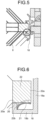
- FIG. 8 is a schematic view of a contact part between the lower guide rail and the heat exchanger in the heat exchange ventilator according to the first embodiment.
- FIG. 8 is a schematic, enlarged illustration of part V illustrated in FIG. 7 .
- the guide rail 18 and the guide rail 19 each include holding parts 20 that hold the heat exchanger 8.
- Each guide rail 18 includes an end-face-facing part 18a, a pair of side-facing parts 18b, and rib-shaped holding parts 20.
- the end-face-facing part 18a extends vertically while facing an end face 22a of the heat exchanger frame 22.
- the pair of side-facing parts 18b each correspondingly connect with an upper or a lower part of the end-face-facing part 18a, extend parallel to sides 22b of the heat exchanger frame 22, and a clearance is provided between each of the side-facing parts 18b and the corresponding side 22b.
- Each of the rib-shaped holding parts 20 connects with corresponding one of the side-facing parts 18b while being spaced apart from the end-face-facing part 18a.
- the holding parts 20 correspondingly project from the upper and lower side-facing parts 18b, and face to each other.
- the guide rail 19 includes an end-face-facing part 19a that extends horizontally while facing an end face 22a of the heat exchanger frame 22, a pair of side-facing parts 19b that connect with a left and a right part of the end-face-facing part 19a and extend parallel to sides 22b of the heat exchanger frame 22, and rib-shaped holding parts 20 that connect with corresponding one of the side-facing parts 19b while being spaced apart from the end-face-facing part 19a.
- These holding parts 20 correspondingly project from the left and right side-facing parts 19b, and face to each other. In other words, each of the holding parts 20 projects from the side-facing part 18b or 19b toward the heat exchanger frame 22.
- Each of the holding parts 20 of the guide rails 18 and 19 are formed to be rib-shaped and thus can have a small area of contact with the heat exchanger frame 22. Therefore, decreased frictional resistance can be achieved when the heat exchanger 8 is detached and attached for maintenance. If a contact part between the holding part 20 and the heat exchanger frame 22 is equivalent to thickness of a resin, the contact can substantially be made as a line contact.
- a seal member 21 is provided integrally with the guide rail 18 in the clearance between the side-facing part 18b and the heat exchanger frame 22, and a seal member 21 is provided integrally with the guide rail 19 in a clearance between the side-facing part 19b and the heat exchanger frame 22.
- Each of the seal members 21 is brought into contact with the heat exchanger frame 22 of the heat exchanger 8 and is pressed against the heat exchanger frame 22 by means of its elasticity that is caused by bending of the seal member 21.
- the seal member 21 that has not been elastically deformed is indicated by a two-dot chain line in FIGS. 6 and 8 .
- the seal members 21 are made of, for example, an elastomer.
- the seal member 21 is provided in the clearance between the side-facing part 18b and the heat exchanger frame 22 as well as in the clearance between the side-facing part 19b and the heat exchanger frame 22.
- Each of the seal members 21 is formed to be of curved-plate shape and is elastically deformable.
- Each of the seal members 21 has one end fixed to the guide rail 18 or 19, and the opposite end as a free end.
- Each of the seal members 21 is fixed to the side-facing part 18b or 19b and abuts against the heat exchanger frame 22 at its curved surface, thus providing a seal.
- each of the holding parts 20 projects from the side-facing part 18b or 19b, it is possible to keep the clearance between the side-facing part 18b and the heat exchanger frame 22 and the clearance between the side-facing part 19b and the heat exchanger frame 22 to be a certain amount or more when a leading end 20a of the holding parts 20 and the heat exchange frame 22 of the heat exchanger 8 come into contact with each other. Therefore, the deformation of the seal member 21 can be kept within a certain amount, and the seal member 21 can stably abut against the heat exchange frame 22, so that the sealing property that can be ensured is stable.
- the deformation of the seal member 21 can be kept within the certain amount, contact pressure between the seal member 21 and the heat exchanger frame 22 can be maintained within a certain value, and frictional resistance can accordingly be decreased, thus achieving improved property for attaching and detaching of the heat exchanger 8.
- the heat exchanger 8 can be supported by the holding parts 20, weight of the heat exchanger 8 is not applied to the seal members 21 when the heat exchanger 8 is attached or detached. Therefore, damage to the seal member 21 can be lessened when the heat exchanger 8 is attached or detached, and improved sliding can also be achieved for the heat exchanger 8 during the attaching or the detaching.
- the material is bent only within its elastic range of deformation and thus has long-lasting elasticity, and additionally, its sealing performance can have improved long-term reliability.
- the other end of the seal member 21 is the free end in the example of the first embodiment but is not limited to this.
- the other end of each of the seal members 21 may be fixed to the end-face-facing part 18a or 19a to have a hollow part in section.
- each of the seal members 21 according to the first embodiment is formed integrally with the guide rail 18 or 19 by two-color molding, a packing made of an expanded foam material does not need to be affixed. Thus, cost of the packing material can be suppressed.
- the seal member 21 and each of the guide rails 18 and 19 can be formed integrally with each other by extrusion molding when, for example, the elastomer is used for the seal member 21 and polypropylene that is a curing resin or acrylonitrile butadiene styrene is used for the guide rails 18 and 19. It is to be noted that each of the seal members 21 may be formed as a member separate from the guide rail 18 or 19 and may be combined with the guide rail 18 or 19.
- Using the resin for the seal member 21 and ensuring the sealing property without completely crushing the seal member 21 can reduce aging degradation of the seal member 21 that might be caused by shaving of the seal member 21 in association with sliding of the heat exchanger 8 for maintenance, and thus can reduce sealing performance deterioration.
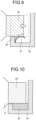
- FIG. 9 is a schematic view of the contact part between the right guide rail and the heat exchanger in a case where the heat exchanger has contracted in the heat exchange ventilator according to the first embodiment.
- the heat exchanger 8 not experiencing contraction is indicated by a broken line in FIG. 9 .
- the seal member 21 not experiencing elastic deformation is indicated by a two-dot chain line.
- the seal member 21 is provided so as to come into contact with the heat exchanger frame 22 in parallel with a direction in which the heat exchanger frame 22 shifts due to the contraction of the heat exchanger 8. Accordingly, even after the heat exchanger frame 22 shifts due to the contraction of the heat exchanger 8, the sealing property is maintained.
- the heat exchanger 8 of the heat exchange ventilator 100 is held by the holding parts 20 of the guide rails 18 and 19, so that an allowance for contact between the heat exchanger frame 22 and each of the seal members 21 of the guide rail 18 and 19 is adjustable.
- the contact part between the heat exchanger frame 22 and each of the guide rails 18 and 19 is minimized, so that the contact parts around the heat exchanger 8 can have reduced contact pressure with respect to directions in which the heat exchanger 8 is removed and inserted for maintenance, thereby decreased frictional resistance can be achieved. Therefore, the heat exchanger 8 can be removed and inserted smoothly, and with air leaks between the supply air passage 5A and the exhaust air passage 5B during installation of the heat exchanger 8 minimized, the maintenance can be simplified.
- the heat exchange ventilator 100 can achieve improved ventilation efficiency.
- Integrally molding each of the guide rails 18 and 19 and the seal member 21 by the two-color molding can decrease an amount to use for the seal members 21 and thus can bring about resource saving.
- Carrying out the two-color molding for the seal member 21 can reduce, as compared with the expanded foam material packing, decrease in sealing property which might be deteriorated over time as the packing is shaved when the heat exchanger 8 is slid.
- FIG. 10 is a schematic view of a contact part between the right guide rail and the heat exchanger in the heat exchange ventilator according to the second embodiment.
- FIG. 11 is a schematic view of a contact part between the lower guide rail and the heat exchanger in the heat exchange ventilator according to the second embodiment.
- the heat exchange ventilator 100 according to the second embodiment is similar in overall structure to the heat exchange ventilator 100 according to the first embodiment.
- a seal member 23 is affixed to each of the guide rails 18 and 19 of the heat exchange ventilator 100 according to the second embodiment.
- the seal member 23 is a packing made of an expanded foam material. It is to be noted that the seal member 23 may be affixed to the heat exchanger frame 22.
- the seal member 23 has only to be capable of providing a seal at least between the heat exchanger frame 22 and the guide rail 18 or 19 and may be changed appropriately.
- the guide rails 18 and 19 of the heat exchange ventilator 100 each include the holding parts 20 projecting from the side-facing parts 18b or 19b, so that a clearance equivalent to a projecting amount of the holding part 20 is secured between each of the side-facing parts 18b and 19b and the heat exchanger frame 22.
- reduced friction can therefore be achieved with the seal member 23 not being completely crushed by the heat exchanger frame 22, so that sealing deterioration that might be caused by attaching and detaching of the heat exchanger 8 can be suppressed between the heat exchanger 8 and each of the guide rails 18 and 19.
Landscapes
- Engineering & Computer Science (AREA)
- Chemical & Material Sciences (AREA)
- Combustion & Propulsion (AREA)
- Mechanical Engineering (AREA)
- General Engineering & Computer Science (AREA)
- Heat-Exchange Devices With Radiators And Conduit Assemblies (AREA)
Claims (7)
- Ventilateur à échange thermique comprenant un carter extérieur (5) comprenant un passage d'admission d'air (5A) par lequel entre un flux d'air d'admission et un passage de rejet d'air (5B) par lequel sort un flux d'air de rejet, et un échangeur thermique (8) installé entre le passage d'admission d'air (5A) et le passage de rejet d'air (5B) pour effectuer un échange thermique entre le flux d'air d'admission et le flux d'air de rejet, l'échangeur thermique (8) comprenant un élément d'échange thermique (8A) en forme de prisme quadrangulaire et des pièces structurelles d'échangeur thermique (22) installées respectivement aux quatre angles de l'élément d'échange thermique (8A), le ventilateur à échange thermique comprenant :une pluralité de rails de guidage (18, 19) installés à l'intérieur du carter extérieur (5) et entrant en prise avec les pièces structurelles d'échangeur thermique pour guider l'échangeur thermique (8) qui est attaché au carter extérieur (5) et détaché de celui-ci,chacun des rails de guidage (18, 19) comprenant : une partie en regard d'une face d'extrémité (18a, 19a) placée en regard d'une face d'extrémité d'une pièce correspondante parmi les pièces structurelles d'échangeur thermique ; une partie en regard d'un côté (18b, 19b) formant un dégagement entre un côté de la pièce structurelle d'échangeur thermique et la partie en regard d'un côté (18b, 19b) ; une partie de maintien (20) faisant saillie à partir de la partie en regard d'un côté (18b, 19b) en direction de la pièce structurelle d'échangeur thermique ; etun élément d'étanchéité (21 ; 23) placé dans le dégagement et fermant hermétiquement un intervalle entre la pièce structurelle d'échangeur thermique et le rail de guidage (18, 19) ;caractérisé en ce qu'une extrémité antérieure de la partie de maintien (20) est accolée au côté de la pièce correspondante parmi les pièces structurelles d'échangeur thermique.
- Ventilateur à échange thermique selon la revendication 1, dans lequel les rails de guidage (18, 19) entrent en prise avec les pièces structurelles d'échangeur thermique au niveau de parties supérieure et inférieure, ou au niveau de parties gauche et droite de l'échangeur thermique (8).
- Ventilateur à échange thermique selon la revendication 1, dans lequel une distance sur laquelle l'élément d'étanchéité (21 ; 23) fait saillie à partir de la partie en regard d'un côté (18b, 19b) est supérieure à une distance sur laquelle la partie de maintien (20) fait saillie à partir de la partie en regard d'un côté (18b, 19b).
- Ventilateur à échange thermique selon la revendication 1, dans lequel l'élément d'étanchéité (21 ; 23) se présente sous la forme d'une plaque incurvée, au moins une extrémité de l'élément d'étanchéité (21 ; 23) est fixée au rail de guidage (18, 19), et une surface incurvée de l'élément d'étanchéité (21 ; 23) est accolée à la pièce structurelle d'échangeur thermique.
- Ventilateur à échange thermique selon l'une quelconque des revendications 1 à 4, dans lequel l'élément d'étanchéité (21) est fait d'un élastomère.
- Ventilateur à échange thermique selon la revendication 5, dans lequel l'élément d'étanchéité (21) et le rail de guidage (18, 19) font corps ensemble.
- Ventilateur à échange thermique selon l'une quelconque des revendications 1 à 4, dans lequel l'élément d'étanchéité (21 ; 23) est fait d'un matériau en mousse expansé.
Applications Claiming Priority (1)
| Application Number | Priority Date | Filing Date | Title |
|---|---|---|---|
| PCT/JP2017/021365 WO2018225224A1 (fr) | 2017-06-08 | 2017-06-08 | Dispositif de ventilation à échange de chaleur |
Publications (3)
| Publication Number | Publication Date |
|---|---|
| EP3637005A1 EP3637005A1 (fr) | 2020-04-15 |
| EP3637005A4 EP3637005A4 (fr) | 2020-06-17 |
| EP3637005B1 true EP3637005B1 (fr) | 2024-05-15 |
Family
ID=64566483
Family Applications (1)
| Application Number | Title | Priority Date | Filing Date |
|---|---|---|---|
| EP17912437.5A Active EP3637005B1 (fr) | 2017-06-08 | 2017-06-08 | Dispositif de ventilation à échange de chaleur |
Country Status (5)
| Country | Link |
|---|---|
| US (1) | US11287149B2 (fr) |
| EP (1) | EP3637005B1 (fr) |
| JP (1) | JPWO2018225224A1 (fr) |
| CN (1) | CN110678700B (fr) |
| WO (1) | WO2018225224A1 (fr) |
Families Citing this family (5)
| Publication number | Priority date | Publication date | Assignee | Title |
|---|---|---|---|---|
| JP7237189B2 (ja) * | 2019-11-12 | 2023-03-10 | 三菱電機株式会社 | 熱交換型換気装置 |
| KR102477942B1 (ko) * | 2020-07-01 | 2022-12-14 | 엘지전자 주식회사 | 천장형 공기조화기 |
| JP7121314B2 (ja) * | 2020-11-30 | 2022-08-18 | ダイキン工業株式会社 | 換気装置 |
| US20250155157A1 (en) * | 2022-04-25 | 2025-05-15 | Mitsubishi Electric Corporation | Heat source unit |
| JP2025133530A (ja) * | 2024-03-01 | 2025-09-11 | ダイキン工業株式会社 | 換気装置 |
Family Cites Families (23)
| Publication number | Priority date | Publication date | Assignee | Title |
|---|---|---|---|---|
| SE8002896L (sv) * | 1980-04-17 | 1981-10-18 | Bahco Ventilation Ab | Vermeatervinningsanordning |
| US4596285A (en) * | 1985-03-28 | 1986-06-24 | North Atlantic Technologies, Inc. | Heat exchanger with resilient corner seals |
| JP2550754B2 (ja) * | 1990-06-20 | 1996-11-06 | ダイキン工業株式会社 | 熱交換換気装置 |
| JPH05248782A (ja) * | 1992-03-06 | 1993-09-24 | Mitsubishi Electric Corp | 熱交換器 |
| JP3173416B2 (ja) * | 1997-04-30 | 2001-06-04 | ダイキン工業株式会社 | 熱交換換気装置 |
| JP2001263752A (ja) | 2000-03-21 | 2001-09-26 | Mitsubishi Electric Corp | 熱交換換気装置 |
| US6641688B1 (en) * | 2001-03-30 | 2003-11-04 | Stephen V. Gearhart | Method for sealing an annular space |
| CN1226570C (zh) * | 2001-03-30 | 2005-11-09 | 大金工业株式会社 | 换气装置及换气装置的组装方法 |
| CN1626959A (zh) * | 2003-12-12 | 2005-06-15 | 乐金电子(天津)电器有限公司 | 换气系统 |
| JP3757976B2 (ja) * | 2004-04-15 | 2006-03-22 | ダイキン工業株式会社 | 熱交換ユニット |
| DE502006005868D1 (de) * | 2005-08-19 | 2010-02-25 | Freudenberg Carl Kg | Befeuchter |
| JP4872428B2 (ja) * | 2006-04-14 | 2012-02-08 | ダイキン工業株式会社 | 換気装置 |
| KR101203998B1 (ko) * | 2006-07-18 | 2012-11-23 | 삼성전자주식회사 | 열교환기와 이를 가지는 환기장치 |
| KR101186016B1 (ko) * | 2008-08-22 | 2012-09-26 | 미쓰비시덴키 가부시키가이샤 | 열교환 환기 장치 |
| KR101149815B1 (ko) * | 2012-01-19 | 2012-05-24 | 은성화학(주) | 전열교환 환기유니트 |
| JP6142503B2 (ja) * | 2012-10-31 | 2017-06-07 | マックス株式会社 | 換気装置 |
| JP6109053B2 (ja) * | 2013-12-10 | 2017-04-05 | 三菱電機株式会社 | 熱交換換気装置 |
| CN104315601A (zh) * | 2014-10-13 | 2015-01-28 | 淄博气宇空调节能设备有限公司 | 新风换气机 |
| JP6377270B2 (ja) * | 2015-05-29 | 2018-08-22 | 三菱電機株式会社 | 熱交換型換気装置 |
| JPWO2017006428A1 (ja) * | 2015-07-07 | 2017-09-28 | 三菱電機株式会社 | 熱交換換気装置 |
| CN206094416U (zh) * | 2016-10-13 | 2017-04-12 | 珠海格力电器股份有限公司 | 热交换芯体的安装结构及通风系统 |
| CN207279902U (zh) * | 2017-03-29 | 2018-04-27 | 艾美特电器(九江)有限公司 | 用于安装热交换芯的导轨 |
| CN110536677B (zh) | 2017-04-18 | 2023-01-03 | 花王株式会社 | 紫外线防御覆膜的制造方法 |
-
2017
- 2017-06-08 WO PCT/JP2017/021365 patent/WO2018225224A1/fr not_active Ceased
- 2017-06-08 EP EP17912437.5A patent/EP3637005B1/fr active Active
- 2017-06-08 JP JP2019523300A patent/JPWO2018225224A1/ja active Pending
- 2017-06-08 CN CN201780091017.4A patent/CN110678700B/zh active Active
- 2017-06-08 US US16/615,864 patent/US11287149B2/en active Active
Also Published As
| Publication number | Publication date |
|---|---|
| CN110678700B (zh) | 2021-08-10 |
| WO2018225224A1 (fr) | 2018-12-13 |
| EP3637005A4 (fr) | 2020-06-17 |
| EP3637005A1 (fr) | 2020-04-15 |
| US11287149B2 (en) | 2022-03-29 |
| CN110678700A (zh) | 2020-01-10 |
| JPWO2018225224A1 (ja) | 2019-11-07 |
| US20200149760A1 (en) | 2020-05-14 |
Similar Documents
| Publication | Publication Date | Title |
|---|---|---|
| EP3637005B1 (fr) | Dispositif de ventilation à échange de chaleur | |
| JP4867727B2 (ja) | 冷却装置 | |
| US10483604B2 (en) | Battery pack | |
| CN101578488B (zh) | 空调机的室外机 | |
| CN102124276B (zh) | 热交换换气装置 | |
| JP6671362B2 (ja) | 熱交換型換気装置 | |
| CN114631220A (zh) | 用于电池系统的电池外壳 | |
| EP3418663B1 (fr) | Échangeur de chaleur et dispositif de ventilation d'échangeur de chaleur | |
| CN115621501A (zh) | 膜加湿器 | |
| KR20150022128A (ko) | 공기조화기 | |
| WO2017158354A1 (fr) | Ensemble lame de persienne doté d'un élément d'étanchéité | |
| WO2017109952A1 (fr) | Dispositif de ventilation à échange de chaleur | |
| JP3039442B2 (ja) | 熱交換器への仕切板取付構造 | |
| JP6537760B1 (ja) | 熱交換素子及び熱交換換気装置 | |
| EP4249818B1 (fr) | Humidificateur | |
| JP7787778B2 (ja) | 電池パックおよび電池パックケース | |
| WO2016194086A1 (fr) | Dispositif de ventilation à échange de chaleur | |
| CN205642103U (zh) | 热交换器、带热交换器的控制装置以及散热器 | |
| CN222654240U (zh) | 防水透气阀和电池 | |
| KR102879058B1 (ko) | 배터리케이스용 통기성 확보 장치 | |
| JP2004003858A (ja) | 換気装置 | |
| CN211823031U (zh) | 用于空调器的风道组件和具有其的空调器 | |
| JP5423087B2 (ja) | 発熱体収納装置 | |
| CN104704298B (zh) | 热交换式换气装置 | |
| CN121772141A (zh) | 一种具有高效泄爆功能的机柜 |
Legal Events
| Date | Code | Title | Description |
|---|---|---|---|
| STAA | Information on the status of an ep patent application or granted ep patent |
Free format text: STATUS: THE INTERNATIONAL PUBLICATION HAS BEEN MADE |
|
| PUAI | Public reference made under article 153(3) epc to a published international application that has entered the european phase |
Free format text: ORIGINAL CODE: 0009012 |
|
| STAA | Information on the status of an ep patent application or granted ep patent |
Free format text: STATUS: REQUEST FOR EXAMINATION WAS MADE |
|
| 17P | Request for examination filed |
Effective date: 20191126 |
|
| AK | Designated contracting states |
Kind code of ref document: A1 Designated state(s): AL AT BE BG CH CY CZ DE DK EE ES FI FR GB GR HR HU IE IS IT LI LT LU LV MC MK MT NL NO PL PT RO RS SE SI SK SM TR |
|
| AX | Request for extension of the european patent |
Extension state: BA ME |
|
| A4 | Supplementary search report drawn up and despatched |
Effective date: 20200515 |
|
| RIC1 | Information provided on ipc code assigned before grant |
Ipc: F24F 7/08 20060101AFI20200511BHEP Ipc: F24F 12/00 20060101ALI20200511BHEP Ipc: F24F 13/30 20060101ALI20200511BHEP |
|
| DAV | Request for validation of the european patent (deleted) | ||
| DAX | Request for extension of the european patent (deleted) | ||
| STAA | Information on the status of an ep patent application or granted ep patent |
Free format text: STATUS: EXAMINATION IS IN PROGRESS |
|
| 17Q | First examination report despatched |
Effective date: 20220609 |
|
| GRAP | Despatch of communication of intention to grant a patent |
Free format text: ORIGINAL CODE: EPIDOSNIGR1 |
|
| STAA | Information on the status of an ep patent application or granted ep patent |
Free format text: STATUS: GRANT OF PATENT IS INTENDED |
|
| INTG | Intention to grant announced |
Effective date: 20231211 |
|
| GRAS | Grant fee paid |
Free format text: ORIGINAL CODE: EPIDOSNIGR3 |
|
| GRAA | (expected) grant |
Free format text: ORIGINAL CODE: 0009210 |
|
| STAA | Information on the status of an ep patent application or granted ep patent |
Free format text: STATUS: THE PATENT HAS BEEN GRANTED |
|
| AK | Designated contracting states |
Kind code of ref document: B1 Designated state(s): AL AT BE BG CH CY CZ DE DK EE ES FI FR GB GR HR HU IE IS IT LI LT LU LV MC MK MT NL NO PL PT RO RS SE SI SK SM TR |
|
| REG | Reference to a national code |
Ref country code: CH Ref legal event code: EP Ref country code: GB Ref legal event code: FG4D |
|
| REG | Reference to a national code |
Ref country code: IE Ref legal event code: FG4D |
|
| REG | Reference to a national code |
Ref country code: DE Ref legal event code: R096 Ref document number: 602017082015 Country of ref document: DE |
|
| REG | Reference to a national code |
Ref country code: LT Ref legal event code: MG9D |
|
| REG | Reference to a national code |
Ref country code: NL Ref legal event code: MP Effective date: 20240515 |
|
| PG25 | Lapsed in a contracting state [announced via postgrant information from national office to epo] |
Ref country code: IS Free format text: LAPSE BECAUSE OF FAILURE TO SUBMIT A TRANSLATION OF THE DESCRIPTION OR TO PAY THE FEE WITHIN THE PRESCRIBED TIME-LIMIT Effective date: 20240915 |
|
| PG25 | Lapsed in a contracting state [announced via postgrant information from national office to epo] |
Ref country code: BG Free format text: LAPSE BECAUSE OF FAILURE TO SUBMIT A TRANSLATION OF THE DESCRIPTION OR TO PAY THE FEE WITHIN THE PRESCRIBED TIME-LIMIT Effective date: 20240515 |
|
| PG25 | Lapsed in a contracting state [announced via postgrant information from national office to epo] |
Ref country code: HR Free format text: LAPSE BECAUSE OF FAILURE TO SUBMIT A TRANSLATION OF THE DESCRIPTION OR TO PAY THE FEE WITHIN THE PRESCRIBED TIME-LIMIT Effective date: 20240515 Ref country code: FI Free format text: LAPSE BECAUSE OF FAILURE TO SUBMIT A TRANSLATION OF THE DESCRIPTION OR TO PAY THE FEE WITHIN THE PRESCRIBED TIME-LIMIT Effective date: 20240515 |
|
| PG25 | Lapsed in a contracting state [announced via postgrant information from national office to epo] |
Ref country code: GR Free format text: LAPSE BECAUSE OF FAILURE TO SUBMIT A TRANSLATION OF THE DESCRIPTION OR TO PAY THE FEE WITHIN THE PRESCRIBED TIME-LIMIT Effective date: 20240816 |
|
| PG25 | Lapsed in a contracting state [announced via postgrant information from national office to epo] |
Ref country code: PT Free format text: LAPSE BECAUSE OF FAILURE TO SUBMIT A TRANSLATION OF THE DESCRIPTION OR TO PAY THE FEE WITHIN THE PRESCRIBED TIME-LIMIT Effective date: 20240916 |
|
| REG | Reference to a national code |
Ref country code: AT Ref legal event code: MK05 Ref document number: 1687201 Country of ref document: AT Kind code of ref document: T Effective date: 20240515 |
|
| PG25 | Lapsed in a contracting state [announced via postgrant information from national office to epo] |
Ref country code: NL Free format text: LAPSE BECAUSE OF FAILURE TO SUBMIT A TRANSLATION OF THE DESCRIPTION OR TO PAY THE FEE WITHIN THE PRESCRIBED TIME-LIMIT Effective date: 20240515 |
|
| PG25 | Lapsed in a contracting state [announced via postgrant information from national office to epo] |
Ref country code: ES Free format text: LAPSE BECAUSE OF FAILURE TO SUBMIT A TRANSLATION OF THE DESCRIPTION OR TO PAY THE FEE WITHIN THE PRESCRIBED TIME-LIMIT Effective date: 20240515 |
|
| PG25 | Lapsed in a contracting state [announced via postgrant information from national office to epo] |
Ref country code: AT Free format text: LAPSE BECAUSE OF FAILURE TO SUBMIT A TRANSLATION OF THE DESCRIPTION OR TO PAY THE FEE WITHIN THE PRESCRIBED TIME-LIMIT Effective date: 20240515 |
|
| PG25 | Lapsed in a contracting state [announced via postgrant information from national office to epo] |
Ref country code: PL Free format text: LAPSE BECAUSE OF FAILURE TO SUBMIT A TRANSLATION OF THE DESCRIPTION OR TO PAY THE FEE WITHIN THE PRESCRIBED TIME-LIMIT Effective date: 20240515 |
|
| PG25 | Lapsed in a contracting state [announced via postgrant information from national office to epo] |
Ref country code: LV Free format text: LAPSE BECAUSE OF FAILURE TO SUBMIT A TRANSLATION OF THE DESCRIPTION OR TO PAY THE FEE WITHIN THE PRESCRIBED TIME-LIMIT Effective date: 20240515 |
|
| PG25 | Lapsed in a contracting state [announced via postgrant information from national office to epo] |
Ref country code: PT Free format text: LAPSE BECAUSE OF FAILURE TO SUBMIT A TRANSLATION OF THE DESCRIPTION OR TO PAY THE FEE WITHIN THE PRESCRIBED TIME-LIMIT Effective date: 20240916 Ref country code: PL Free format text: LAPSE BECAUSE OF FAILURE TO SUBMIT A TRANSLATION OF THE DESCRIPTION OR TO PAY THE FEE WITHIN THE PRESCRIBED TIME-LIMIT Effective date: 20240515 Ref country code: NO Free format text: LAPSE BECAUSE OF FAILURE TO SUBMIT A TRANSLATION OF THE DESCRIPTION OR TO PAY THE FEE WITHIN THE PRESCRIBED TIME-LIMIT Effective date: 20240815 Ref country code: NL Free format text: LAPSE BECAUSE OF FAILURE TO SUBMIT A TRANSLATION OF THE DESCRIPTION OR TO PAY THE FEE WITHIN THE PRESCRIBED TIME-LIMIT Effective date: 20240515 Ref country code: LV Free format text: LAPSE BECAUSE OF FAILURE TO SUBMIT A TRANSLATION OF THE DESCRIPTION OR TO PAY THE FEE WITHIN THE PRESCRIBED TIME-LIMIT Effective date: 20240515 Ref country code: IS Free format text: LAPSE BECAUSE OF FAILURE TO SUBMIT A TRANSLATION OF THE DESCRIPTION OR TO PAY THE FEE WITHIN THE PRESCRIBED TIME-LIMIT Effective date: 20240915 Ref country code: HR Free format text: LAPSE BECAUSE OF FAILURE TO SUBMIT A TRANSLATION OF THE DESCRIPTION OR TO PAY THE FEE WITHIN THE PRESCRIBED TIME-LIMIT Effective date: 20240515 Ref country code: GR Free format text: LAPSE BECAUSE OF FAILURE TO SUBMIT A TRANSLATION OF THE DESCRIPTION OR TO PAY THE FEE WITHIN THE PRESCRIBED TIME-LIMIT Effective date: 20240816 Ref country code: FI Free format text: LAPSE BECAUSE OF FAILURE TO SUBMIT A TRANSLATION OF THE DESCRIPTION OR TO PAY THE FEE WITHIN THE PRESCRIBED TIME-LIMIT Effective date: 20240515 Ref country code: ES Free format text: LAPSE BECAUSE OF FAILURE TO SUBMIT A TRANSLATION OF THE DESCRIPTION OR TO PAY THE FEE WITHIN THE PRESCRIBED TIME-LIMIT Effective date: 20240515 Ref country code: BG Free format text: LAPSE BECAUSE OF FAILURE TO SUBMIT A TRANSLATION OF THE DESCRIPTION OR TO PAY THE FEE WITHIN THE PRESCRIBED TIME-LIMIT Effective date: 20240515 Ref country code: AT Free format text: LAPSE BECAUSE OF FAILURE TO SUBMIT A TRANSLATION OF THE DESCRIPTION OR TO PAY THE FEE WITHIN THE PRESCRIBED TIME-LIMIT Effective date: 20240515 Ref country code: RS Free format text: LAPSE BECAUSE OF FAILURE TO SUBMIT A TRANSLATION OF THE DESCRIPTION OR TO PAY THE FEE WITHIN THE PRESCRIBED TIME-LIMIT Effective date: 20240815 |
|
| PG25 | Lapsed in a contracting state [announced via postgrant information from national office to epo] |
Ref country code: DK Free format text: LAPSE BECAUSE OF FAILURE TO SUBMIT A TRANSLATION OF THE DESCRIPTION OR TO PAY THE FEE WITHIN THE PRESCRIBED TIME-LIMIT Effective date: 20240515 |
|
| PG25 | Lapsed in a contracting state [announced via postgrant information from national office to epo] |
Ref country code: EE Free format text: LAPSE BECAUSE OF FAILURE TO SUBMIT A TRANSLATION OF THE DESCRIPTION OR TO PAY THE FEE WITHIN THE PRESCRIBED TIME-LIMIT Effective date: 20240515 |
|
| PG25 | Lapsed in a contracting state [announced via postgrant information from national office to epo] |
Ref country code: CZ Free format text: LAPSE BECAUSE OF FAILURE TO SUBMIT A TRANSLATION OF THE DESCRIPTION OR TO PAY THE FEE WITHIN THE PRESCRIBED TIME-LIMIT Effective date: 20240515 |
|
| PG25 | Lapsed in a contracting state [announced via postgrant information from national office to epo] |
Ref country code: SK Free format text: LAPSE BECAUSE OF FAILURE TO SUBMIT A TRANSLATION OF THE DESCRIPTION OR TO PAY THE FEE WITHIN THE PRESCRIBED TIME-LIMIT Effective date: 20240515 Ref country code: RO Free format text: LAPSE BECAUSE OF FAILURE TO SUBMIT A TRANSLATION OF THE DESCRIPTION OR TO PAY THE FEE WITHIN THE PRESCRIBED TIME-LIMIT Effective date: 20240515 |
|
| PG25 | Lapsed in a contracting state [announced via postgrant information from national office to epo] |
Ref country code: SM Free format text: LAPSE BECAUSE OF FAILURE TO SUBMIT A TRANSLATION OF THE DESCRIPTION OR TO PAY THE FEE WITHIN THE PRESCRIBED TIME-LIMIT Effective date: 20240515 |
|
| PG25 | Lapsed in a contracting state [announced via postgrant information from national office to epo] |
Ref country code: SM Free format text: LAPSE BECAUSE OF FAILURE TO SUBMIT A TRANSLATION OF THE DESCRIPTION OR TO PAY THE FEE WITHIN THE PRESCRIBED TIME-LIMIT Effective date: 20240515 Ref country code: SK Free format text: LAPSE BECAUSE OF FAILURE TO SUBMIT A TRANSLATION OF THE DESCRIPTION OR TO PAY THE FEE WITHIN THE PRESCRIBED TIME-LIMIT Effective date: 20240515 Ref country code: RO Free format text: LAPSE BECAUSE OF FAILURE TO SUBMIT A TRANSLATION OF THE DESCRIPTION OR TO PAY THE FEE WITHIN THE PRESCRIBED TIME-LIMIT Effective date: 20240515 Ref country code: EE Free format text: LAPSE BECAUSE OF FAILURE TO SUBMIT A TRANSLATION OF THE DESCRIPTION OR TO PAY THE FEE WITHIN THE PRESCRIBED TIME-LIMIT Effective date: 20240515 Ref country code: DK Free format text: LAPSE BECAUSE OF FAILURE TO SUBMIT A TRANSLATION OF THE DESCRIPTION OR TO PAY THE FEE WITHIN THE PRESCRIBED TIME-LIMIT Effective date: 20240515 Ref country code: CZ Free format text: LAPSE BECAUSE OF FAILURE TO SUBMIT A TRANSLATION OF THE DESCRIPTION OR TO PAY THE FEE WITHIN THE PRESCRIBED TIME-LIMIT Effective date: 20240515 |
|
| REG | Reference to a national code |
Ref country code: CH Ref legal event code: PL |
|
| PG25 | Lapsed in a contracting state [announced via postgrant information from national office to epo] |
Ref country code: IT Free format text: LAPSE BECAUSE OF FAILURE TO SUBMIT A TRANSLATION OF THE DESCRIPTION OR TO PAY THE FEE WITHIN THE PRESCRIBED TIME-LIMIT Effective date: 20240515 Ref country code: MC Free format text: LAPSE BECAUSE OF FAILURE TO SUBMIT A TRANSLATION OF THE DESCRIPTION OR TO PAY THE FEE WITHIN THE PRESCRIBED TIME-LIMIT Effective date: 20240515 |
|
| PG25 | Lapsed in a contracting state [announced via postgrant information from national office to epo] |
Ref country code: LU Free format text: LAPSE BECAUSE OF NON-PAYMENT OF DUE FEES Effective date: 20240608 |
|
| REG | Reference to a national code |
Ref country code: DE Ref legal event code: R097 Ref document number: 602017082015 Country of ref document: DE |
|
| PLBE | No opposition filed within time limit |
Free format text: ORIGINAL CODE: 0009261 |
|
| STAA | Information on the status of an ep patent application or granted ep patent |
Free format text: STATUS: NO OPPOSITION FILED WITHIN TIME LIMIT |
|
| PG25 | Lapsed in a contracting state [announced via postgrant information from national office to epo] |
Ref country code: IE Free format text: LAPSE BECAUSE OF NON-PAYMENT OF DUE FEES Effective date: 20240608 |
|
| 26N | No opposition filed |
Effective date: 20250218 |
|
| PG25 | Lapsed in a contracting state [announced via postgrant information from national office to epo] |
Ref country code: SI Free format text: LAPSE BECAUSE OF FAILURE TO SUBMIT A TRANSLATION OF THE DESCRIPTION OR TO PAY THE FEE WITHIN THE PRESCRIBED TIME-LIMIT Effective date: 20240515 Ref country code: BE Free format text: LAPSE BECAUSE OF NON-PAYMENT OF DUE FEES Effective date: 20240630 Ref country code: CH Free format text: LAPSE BECAUSE OF NON-PAYMENT OF DUE FEES Effective date: 20240630 |
|
| PG25 | Lapsed in a contracting state [announced via postgrant information from national office to epo] |
Ref country code: FR Free format text: LAPSE BECAUSE OF NON-PAYMENT OF DUE FEES Effective date: 20240715 |
|
| REG | Reference to a national code |
Ref country code: BE Ref legal event code: MM Effective date: 20240630 |
|
| PGFP | Annual fee paid to national office [announced via postgrant information from national office to epo] |
Ref country code: DE Payment date: 20250429 Year of fee payment: 9 |
|
| PGFP | Annual fee paid to national office [announced via postgrant information from national office to epo] |
Ref country code: GB Payment date: 20250501 Year of fee payment: 9 |
|
| PG25 | Lapsed in a contracting state [announced via postgrant information from national office to epo] |
Ref country code: SE Free format text: LAPSE BECAUSE OF FAILURE TO SUBMIT A TRANSLATION OF THE DESCRIPTION OR TO PAY THE FEE WITHIN THE PRESCRIBED TIME-LIMIT Effective date: 20240515 |
|
| PG25 | Lapsed in a contracting state [announced via postgrant information from national office to epo] |
Ref country code: CY Free format text: LAPSE BECAUSE OF FAILURE TO SUBMIT A TRANSLATION OF THE DESCRIPTION OR TO PAY THE FEE WITHIN THE PRESCRIBED TIME-LIMIT; INVALID AB INITIO Effective date: 20170608 |
|
| PG25 | Lapsed in a contracting state [announced via postgrant information from national office to epo] |
Ref country code: HU Free format text: LAPSE BECAUSE OF FAILURE TO SUBMIT A TRANSLATION OF THE DESCRIPTION OR TO PAY THE FEE WITHIN THE PRESCRIBED TIME-LIMIT; INVALID AB INITIO Effective date: 20170608 |