EP3637007A1 - Raumsteuergerät mit einem drehbaren element - Google Patents
Raumsteuergerät mit einem drehbaren element Download PDFInfo
- Publication number
- EP3637007A1 EP3637007A1 EP19201779.6A EP19201779A EP3637007A1 EP 3637007 A1 EP3637007 A1 EP 3637007A1 EP 19201779 A EP19201779 A EP 19201779A EP 3637007 A1 EP3637007 A1 EP 3637007A1
- Authority
- EP
- European Patent Office
- Prior art keywords
- room controller
- rotatable member
- support member
- controller according
- circuit board
- Prior art date
- Legal status (The legal status is an assumption and is not a legal conclusion. Google has not performed a legal analysis and makes no representation as to the accuracy of the status listed.)
- Granted
Links
Images

Classifications
-
- H—ELECTRICITY
- H01—ELECTRIC ELEMENTS
- H01H—ELECTRIC SWITCHES; RELAYS; SELECTORS; EMERGENCY PROTECTIVE DEVICES
- H01H19/00—Switches operated by an operating part which is rotatable about a longitudinal axis thereof and which is acted upon directly by a solid body external to the switch, e.g. by a hand
- H01H19/54—Switches operated by an operating part which is rotatable about a longitudinal axis thereof and which is acted upon directly by a solid body external to the switch, e.g. by a hand the operating part having at least five or an unspecified number of operative positions
- H01H19/60—Angularly-movable actuating part carrying no contacts
-
- F—MECHANICAL ENGINEERING; LIGHTING; HEATING; WEAPONS; BLASTING
- F24—HEATING; RANGES; VENTILATING
- F24F—AIR-CONDITIONING; AIR-HUMIDIFICATION; VENTILATION; USE OF AIR CURRENTS FOR SCREENING
- F24F11/00—Control or safety arrangements
- F24F11/50—Control or safety arrangements characterised by user interfaces or communication
-
- F—MECHANICAL ENGINEERING; LIGHTING; HEATING; WEAPONS; BLASTING
- F24—HEATING; RANGES; VENTILATING
- F24F—AIR-CONDITIONING; AIR-HUMIDIFICATION; VENTILATION; USE OF AIR CURRENTS FOR SCREENING
- F24F11/00—Control or safety arrangements
- F24F11/50—Control or safety arrangements characterised by user interfaces or communication
- F24F11/52—Indication arrangements, e.g. displays
-
- F—MECHANICAL ENGINEERING; LIGHTING; HEATING; WEAPONS; BLASTING
- F24—HEATING; RANGES; VENTILATING
- F24F—AIR-CONDITIONING; AIR-HUMIDIFICATION; VENTILATION; USE OF AIR CURRENTS FOR SCREENING
- F24F11/00—Control or safety arrangements
- F24F11/88—Electrical aspects, e.g. circuits
-
- H—ELECTRICITY
- H01—ELECTRIC ELEMENTS
- H01H—ELECTRIC SWITCHES; RELAYS; SELECTORS; EMERGENCY PROTECTIVE DEVICES
- H01H19/00—Switches operated by an operating part which is rotatable about a longitudinal axis thereof and which is acted upon directly by a solid body external to the switch, e.g. by a hand
- H01H19/005—Electromechanical pulse generators
-
- H—ELECTRICITY
- H05—ELECTRIC TECHNIQUES NOT OTHERWISE PROVIDED FOR
- H05F—STATIC ELECTRICITY; NATURALLY-OCCURRING ELECTRICITY
- H05F3/00—Carrying-off electrostatic charges
- H05F3/02—Carrying-off electrostatic charges by means of earthing connections
-
- H—ELECTRICITY
- H05—ELECTRIC TECHNIQUES NOT OTHERWISE PROVIDED FOR
- H05K—PRINTED CIRCUITS; CASINGS OR CONSTRUCTIONAL DETAILS OF ELECTRIC APPARATUS; MANUFACTURE OF ASSEMBLAGES OF ELECTRICAL COMPONENTS
- H05K9/00—Screening of apparatus or components against electric or magnetic fields
-
- G—PHYSICS
- G05—CONTROLLING; REGULATING
- G05G—CONTROL DEVICES OR SYSTEMS INSOFAR AS CHARACTERISED BY MECHANICAL FEATURES ONLY
- G05G1/00—Controlling members, e.g. knobs or handles; Assemblies or arrangements thereof; Indicating position of controlling members
- G05G1/08—Controlling members for hand actuation by rotary movement, e.g. hand wheels
-
- H—ELECTRICITY
- H01—ELECTRIC ELEMENTS
- H01H—ELECTRIC SWITCHES; RELAYS; SELECTORS; EMERGENCY PROTECTIVE DEVICES
- H01H19/00—Switches operated by an operating part which is rotatable about a longitudinal axis thereof and which is acted upon directly by a solid body external to the switch, e.g. by a hand
- H01H19/02—Details
- H01H19/10—Movable parts; Contacts mounted thereon
- H01H19/14—Operating parts, e.g. turn knob
-
- H—ELECTRICITY
- H01—ELECTRIC ELEMENTS
- H01H—ELECTRIC SWITCHES; RELAYS; SELECTORS; EMERGENCY PROTECTIVE DEVICES
- H01H9/00—Details of switching devices, not covered by groups H01H1/00 - H01H7/00
- H01H9/12—Means for earthing parts of switch not normally conductively connected to the contacts
-
- H—ELECTRICITY
- H05—ELECTRIC TECHNIQUES NOT OTHERWISE PROVIDED FOR
- H05K—PRINTED CIRCUITS; CASINGS OR CONSTRUCTIONAL DETAILS OF ELECTRIC APPARATUS; MANUFACTURE OF ASSEMBLAGES OF ELECTRICAL COMPONENTS
- H05K1/00—Printed circuits
- H05K1/02—Details
- H05K1/0213—Electrical arrangements not otherwise provided for
- H05K1/0216—Reduction of cross-talk, noise or electromagnetic interference
-
- H—ELECTRICITY
- H05—ELECTRIC TECHNIQUES NOT OTHERWISE PROVIDED FOR
- H05K—PRINTED CIRCUITS; CASINGS OR CONSTRUCTIONAL DETAILS OF ELECTRIC APPARATUS; MANUFACTURE OF ASSEMBLAGES OF ELECTRICAL COMPONENTS
- H05K1/00—Printed circuits
- H05K1/02—Details
- H05K1/0213—Electrical arrangements not otherwise provided for
- H05K1/0254—High voltage adaptations; Electrical insulation details; Overvoltage or electrostatic discharge protection ; Arrangements for regulating voltages or for using plural voltages
- H05K1/0257—Overvoltage protection
- H05K1/0259—Electrostatic discharge [ESD] protection
-
- H—ELECTRICITY
- H05—ELECTRIC TECHNIQUES NOT OTHERWISE PROVIDED FOR
- H05K—PRINTED CIRCUITS; CASINGS OR CONSTRUCTIONAL DETAILS OF ELECTRIC APPARATUS; MANUFACTURE OF ASSEMBLAGES OF ELECTRICAL COMPONENTS
- H05K2201/00—Indexing scheme relating to printed circuits covered by H05K1/00
- H05K2201/10—Details of components or other objects attached to or integrated in a printed circuit board
- H05K2201/10227—Other objects, e.g. metallic pieces
- H05K2201/10371—Shields or metal cases
Definitions
- the application relates to a room controller comprising a rotatable member, which is rotatable by a user for adjusting environmental conditions.
- Room controllers are used to control and adjust environmental conditions, like thermal conditions and air quality.
- An example of room controllers are thermostats.
- Room may refer to one or more rooms, indoors or alike interiors, for example of homes, apartments, constructions, public buildings, cottages, cabins, portable buildings/interiors or transportation means.
- a room controller may comprise a rotatable member or a knob, which may be adjusted by a user in order to adjust and control thermal conditions of an environment within a building or a structure.
- a room controller may comprise a display for displaying information. The display may be placed inside the rotatable knob.
- a rotatable knob with a display which is arranged to present the current information and adjustment(s), enables easy and self-directive use of the room controller.
- Object of the invention is to provide a reliable room controller, which is comfortable to use and handle.
- One object is to enable use of metal parts in a room controller.
- a rotatable member provides easy and handy user interface enabling controlling adjustment(s) in an untutored, self-directive way.
- relationship, effects and connections between parts of the room controller are taken into account.
- a rotating member may induce static electricity. Further, it is desired to freely select materials of parts and components.
- a rotatable member may comprise or be comprised of metal.
- the rotatable member may induce or form a source of a static electricity.
- a metal part of a rotatable member of a room controller may cause sudden flow of electricity between the room controller and a user or other electrically charged object.
- Static electricity may cause defects, malfunctioning or breaking of other parts of a room controller. For example, electric parts on a circuit board and a display are vulnerable to static electricity. In order to avoid such defects and uncontrolled static electricity, a rotatable member is grounded.
- a room controller comprises a rotatable member for controlling adjustment(s) of the thermostat, wherein the rotatable member is rotatably connected to a circuit board of the room controller via a support member comprising conductive plastic.
- the rotatable member may comprise metal.
- the conductive plastic enables providing a safe and secure grounding for the rotatable member.
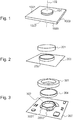
- FIG 1 illustrates a room controller 100 comprising a rotatable member 101.
- the room controller 100 comprises a housing, which may be designed to have any suitable form, like a round, an oval, a square or other form different from a rectangular as illustrated in Figure 1 .
- the housing comprises a back surface 1002 and a front surface 1001, separated from each other by side surface(s) 1003.
- the rotatable member 101 may protrude or project outward from the front surface 1001 of the room controller and/or the rotatable member 101 may comprise a gripping surface. Protrusion and/or gripping surface of the rotatable member 101 enables a user to rotate the rotatable member.
- the gripping surface may comprise a form, material or a prepared surface for enabling gripping by a user.
- the rotatable member 101 enables controlling adjustment(s) of the room controller 100 mechanically. User may adjust environmental conditions by rotating the rotatable member 101.
- the rotatable member 101 is arranged to rotate around rotating axis 102, which is perpendicular to the front surface 1001 of the rotatable member 101 and/or of the room controller 100.
- the rotatable member 101 has positions along its rotational motion and a desired parameter value is identified by the position of the rotatable member 101, or by the change of the position.
- a rotatable member may comprise conductive material.
- the rotatable member may be made of conductive material.
- the rotatable member may comprise a portion, a circular part or a coating of conductive material.
- Conductive material may be electrically conductive and permit motion of electric charge through its volume.
- Conductive material may comprise metal, titanium, steel, aluminium, silver, chrome, gold, copper, platinum, tin, cobalt, iron, conductive ceramic, conductive plastic, or other conductive material, and/or a mixture comprising such.
- Figure 2 illustrates a rotatable member 201 and a circuit board 203.
- the circuit board 203 may be fixed to a back surface or a base part of a housing of a room controller.
- Electronic components are connected to one or more circuit boards of the room controller.
- Electronic components and one or more circuit boards are housed by the room controller housing.
- the rotatable member 201 is arranged to rotate in relation to the circuit board 203 and in relation to the room controller housing.
- the rotatable member 201 is rotatably connected to the circuit board 201 via a support member 202.
- the rotatable member 201 is rotatably connected to a support member 202, which is mounted to the circuit board 203.
- the support member 202 is non-rotatable.
- the support member 202 comprises conductive plastic and is arranged to ground the rotatable member 201.
- the rotatable member 201 may comprise conductive material, like metal, which may form a source of induced static electricity. Rotating of the rotatable member 201 may create static electricity, frictional electricity or electric charging.
- the rotatable member 201 is rotatably connected to the support member 202 such that the two are arranged at least partly in contact. For example, external surface of the support member 202, or parts of it, are arranged to contact internal surface of the rotatable member 201, at least partly. Contact surfaces of the members 201, 202 are arranged to slide in relation to each other.
- Electrons may be exchanged between the rotatable member 201 and the support member 202 arranged in contact with each other. Electrical charges may move between contact surfaces of the rotatable member 201 and the support member 202 in order to equalize their electro(chemical) potential. This creates net charge imbalance between the contact surfaces. Imbalance or charge remains until it is able to uncharge, for example by means of electric current or electrical discharge. Uncharging may cause a sudden flow of electricity from a room controller or metallic part. In order to avoid uncontrolled electrical discharges or electric currents, the rotatable member 201 is grounded via the support member 202, to the ground on the circuit board 203. The support member 201 may electrically shield electronic components of the circuit board 203.
- a support member comprises or is made of conductive plastic.
- Conductive plastic may comprise conductive polymers or intrinsically conducting organic polymers having ability to conduct electricity.
- a polymer may comprise conductive substance(s), for example carbon.
- Conductive plastic may comprise polycarbonates (PC), acrylonitrile butadiene styrene (ABS), polyoxymethylene (POM), polyamides (PA) or any mixtures comprising any of such.
- Conductive plastic may comprise polyanilines (PANI), polyacetylenes (PAC), polypyrroles (PPY), polyindole or their copolymers.
- Conductive plastic may comprise poly(fluorene)s, polyhenylenes, polypyrenes, polyazulenes, polynaphthalenes, poly(p-phenylene vinylene) (PPV), polycarbazoles, polyazepines, poly(thiophene)s (PT), poly(3,4-ethylenedioxythiophene) (PEDOT) or poly(p-phenylene sulphide) (PPS).
- a support member comprising conductive polymer or plastic enables protecting and/or shielding against electromagnetic interference (EMI) and electrostatic discharge (ESD).
- EMI electromagnetic interference
- ESD electrostatic discharge
- FIG. 3 illustrates a rotatable member and a circuit board for a room controller.
- a rotatable member 301 forms a rotatable knob of a room controller, which enables user to adjust environmental conditions by rotating the knob.
- Use of conductive material, like metal, as part of the room controller, for example in cylindrical shell surface of the rotatable member 301, may have positive effect on user experience, visual experience, touch feedback, robustness, rigidity and/or design of a room controller.
- a rotatable member 301 comprises a cylindrical shell surface which is arranged at least substantially perpendicular with the front surface of the room controller.
- An upper or external end surface of the cylindrical rotatable member 301 may be open ended or closed by a lid surface.
- Another component may be situated in the middle of an open ended cylindrical rotatable member 301.
- a display may be situated in place of the upper lid of the cylindrical rotatable member 301.
- the display may form an external surface of the room controller and be surrounded by the rotatable member.
- a lower or a base end surface of the cylindrical rotatable member 301 is open, without a lid surface.
- a lower end of a cylindrical rotatable member 301 is placed towards a circuit board 303.
- a rotatable member 301 may comprise a hollow cylindrical structure, a circular edge portion, a ring or some other form or shape.
- the rotatable member 301 is shaped so that the rotatable movement of it is enabled.
- a structure of the rotatable member 301 may comprise straight, angulated or rounded cylindrical surface.
- the rotatable member 301 may comprise a form of a truncated cone, or of a convex cylindrical shell.
- the rotatable member 301 may comprise a ring, a portion, a coating and/or a cylindrical shell of conductive material.
- the conductive material of the rotatable member 301 may comprise metal, ceramic or other conductive material.
- the rotatable member 301 may be rotatably attached to a support member 302, which is attached to a circuit board 303.
- a support member 302 may be fixedly attached to a circuit board 303 via mechanical and/or adhesive connection(s).
- Mechanical connection may comprise screw, rivet, snap lock, or other mechanical connections.
- Adhesive connection may comprise adhesive, paste, cement or alike bonding agent.
- the support member 302 may be grounded or joined to a ground via the connection(s).
- the support member 302 may comprise an external side surface 3021, which is arranged at least partly to correspond to form of the internal cylindrical surface of the rotatable member 301.
- the support member 302 may comprise a continuous circular portion, like a ring.
- the support member 302 may comprise an O-shaped structure, a U-shaped structure or a J-shaped structure, for example.
- the structure of the support member 302 may be formed of gear- or tooth-like portions, or triangular-, square-, line-, or bar-like portions.
- the portions may have angled or rounded shape.
- the portions are arranged to form a fixed counter part for the rotatable member 301, against which the rotatable member 301 is, at least partly, arranged in a sliding connection via connection surfaces.
- the support member 302 of Figure 3 is made of rectangular portions, which are arranged next to each other in order to form a continuous circle or ring structure. Instead of a closed or continuous structure, the support member may comprise an open or a discontinuous structure.
- the support member may be connected to a ground via more than one connection points or places.
- the support member 302 or portions of it may protrude upwards from the circuit board 303, perpendicular to a surface of the circuit board 303.
- the circuit board 303 may be next to and/or parallel with a back surface of the room controller housing.
- the support member 302 may extend between back and front surfaces of the room controller housing.
- Portions of the support member 302 may be arranged next to each other in order to form a continuous or a discontinuous structure.
- a structure or portions departing from a continuous closed ring may enable flexibility to the structure and placement of the support member 302, as well as other components on a circuit board 303.
- Structure of the support member 302 enables fitting wide areas of contact surfaces 3021, 3022 next to and in contact with the rotatable member 301.
- External surface area(s) 3021 of the support member 302, which is/are extending between the circuit board 303 and the front surface of the room controller housing, may be arranged in contact with the inner surface of the rotatable member 301.
- the support member 302 may have effect of protecting and/or shielding the components attached to the one/more circuit board(s) of the room controller.
- a room controller may comprise parts and/or components capable of forming a wireless connection.
- the parts and/or component may have remote access to, or receive data from an external sensor, for example.
- a radio frequency (RF) block of a room controller may be shielded against interferences.
- the support member 302 may provide an integrated ESD and EMI shield, including an RF shield, for the room controller.
- a room controller may comprise a coder ring 304, which is rotatable.
- the coder ring 304 may be arranged to rotate with the rotatable member 301.
- the coder ring 304 may be an integral part of the rotatable member 301, or a separate part connectable to it, for example next to internal surface of the rotatable member 301.
- the coder ring 304 may form, at least partially, an inner cylindrical surface of the rotatable member 301.
- the coder ring 304 may be arranged at least partly in contact with the support member 302.
- the coder ring 304 comprises conductive material.
- the conductive material of the coder ring 304 may comprise similar conductive materials as the support member 302.
- conductive materials of the two may differ from each other. Use of the same conductive material on the sliding contact surface(s) may lead to wearing of materials.
- the conductive materials used are selected such that the materials enable forming workable and wear resistant sliding contact surfaces between the support member 302 and the coder ring 304.
- the rotatable member 301 and the coder ring 304 are grounded via support member 302.
- the support member 302 may comprise external surface areas 3021, 3022 arranged at least partly in contact with the surface of the coder ring 304.
- the surfaces may be arranged in contact such that the coder ring 304 is arranged in a sliding and rotatable contact with the support member 302.
- the support member 302 may comprise vertical 3021 and/or horizontal 3022 contact surfaces.
- the contact surfaces 3021, 3022 may be adapted to be in contact with an internal cylindrical surface of the rotatable coder ring 304.
- the contact surfaces 3021, 3022 of the support member 302 that are arranged to contact with the coder ring 304 may be called a contact surface, a sliding surface or a sliding contact surface.
- the contact surface enables the rotatable member 301 to be rotated in relation to the support member 302, while the rotatable member 301 is remained in contact with the support member 302. This enables large contact surface between the rotatable member 301 and the support member 302. This enables safe and secure ground connection of the rotatable member via the sliding surface area. Safe and secure ground connection provides safe and secure shielding against ESD and EMI.
- an external conductive part of the room controller may be fixed, non-movable.
- the external conductive part may be a metal ring attached to a housing of the room controller.
- a rotatable member may rotate between the fixed external conductive part and the support member.
- a rotatable member may comprise an external gripping surface in order to enable rotation of it by a user.
- the rotatable member as well as the fixed external conductive part are grounded via the support member.
- Figure 4 illustrates a room controller according to an embodiment.
- the room controller is shown at its front surface and it comprises a rotatable member 401 and display 402.
- a display 402 is placed in the middle of the rotatable member 401.
- the display 402 may be covered by a surface component, which may comprise glass or plastic, for example.
- the external surface of the display 402 and the rotatable member 401 surrounding it may be placed at least approximately at the same level above the front surface of the room controller.
- the rotatable member 401 may comprise a gripping surface arranged parallel with and/or perpendicular to the front surface of the room controller housing.
- the display 402 is illustrated separately next to a room controller in Figure 4 .
- the display 402 may comprise a liquid crystal display.
- the display 402 may comprise a display driver 4021 for controlling the display and electrical connections 4022 for electrically connecting the display, for example to a circuit board.
- the electrical connections 4022 may comprise flexible connections.
- a display driver 4021 may be part of a display module or separate from it, attached to a circuit board or next to the display 402.
- a display 402, a display driver 4021 and/or connections 4022 of the display 402 may be shielded by a support member, which is fixedly attached to a circuit board.
- a display is arranged to present adjustment(s) of a room controller.
- a display is non-rotatably and electrically connected to a circuit board of a room controller.
- a rotatable member may form a continuous surround portion for a display placed at the front surface of a room controller housing. The display is non-rotatable and the rotatable member is rotatable in relation to the display.
- a rotatable member may comprise a circular surface portion 501, which corresponds to a form and thickness of a cylindrical shell of the rotatable member.
- the circular surface portion 501 and/or cylindrical shell portion may comprise slots or alike form in order to provide a surface for gripping for a user.
- a rotatable member may comprise a surface portion 502 inverted inwards from a cylindrical shell portion in order to form a partial lid surface, which may surround an open middle portion.
- the partial lid surface may be inverted slightly upwards or downwards from the cylindrical shell edge.
- a circuit board may comprise a printed circuit board or a printed wired board.
- a thermostat may comprise one or more circuit boards.
- a circuit board may be single-sided or double-sided and/or multi-layered. The circuit board is arranged to electrically connect electronic components and support those mechanically. Electronic components may be mounted via through hole or be surface mounted to a circuit board.
- Position of the rotatable member may be identified.
- Position detection may comprise electrical, optical, mechanical or magnetic means for detecting and sensing position.
- Mechanical position detection is based on detecting mechanical movement of the rotatable ring.
- a gear tooth structure or alike may be provided.
- a potentiometer, encoder or other suitable means may be used for converting mechanical position of the rotatable member to a corresponding electrical signal.
- Magnetic position detection is based on detecting magnetic changes, like change of polarity, magnetic resistance. For example, a magnetic ring may be placed inside the rotating member and rotation of it may be detected by a sensor.
- a mechanical position detection may have effect of causing less electrical or magnetic interference compared to electrical or magnetic position detection.
- a mechanical position detection may be less sensitive to interferences than electrical or magnetic ones.
- Figure 6 illustrates mechanical position detection for a rotation member.
- Switches 6011, 6012 are joined to a circuit board 603.
- the switches 6011, 6012 are situated next to a support member 602 along a rotational moving path of a cylindrical shell edge of a rotating member or a coder ring 604.
- the cylindrical shell edge of the rotating member or the coder ring 604, that is insertable against and/or towards the circuit board 603, comprises a toothed edge surface, or projections or forms departing from even surface.
- Two separate, different kind of coder rings 604 are illustrated in Figure 6 .
- the upper coder ring 604 comprises cylindrical cell of equal thickness, while the lower coder ring 604 comprises thicker toothed lower edge compared to the cylinder cell thickness of it.
- the lower coder ring 604 enables wider toothed area next to and towards the circuit board 603.
- the toothed edge surface enable detecting positional steps or phases of rotational movement via switches 6011, 6012. Any one of the switches 6011, 6012 may be used to detect rotation position.
- An encoder may be used for converting mechanical position of the rotatable member to a corresponding electrical signal. Counting pulses of a generated output signal enables determining position of the rotatable member. Rotation direction of the rotatable member may be determined using two switches 6011, 6012.
- a separate coder ring enables detecting rotational place of a rotatable member mechanically.
- the mechanical position detection may be implemented with less electronic components compared to e.g. electrical or magnetic position detection. Electronic components may be sensitive and/or source of interference.
- a separate coder ring enables utilization of complex forms, for example a toothed surface for position detection. If a sole rotating member, without a coder ring, is used, different kind of position detection may be employed.
Landscapes
- Engineering & Computer Science (AREA)
- Chemical & Material Sciences (AREA)
- Combustion & Propulsion (AREA)
- Mechanical Engineering (AREA)
- General Engineering & Computer Science (AREA)
- Human Computer Interaction (AREA)
- Microelectronics & Electronic Packaging (AREA)
- Shielding Devices Or Components To Electric Or Magnetic Fields (AREA)
- Air Conditioning Control Device (AREA)
- Elimination Of Static Electricity (AREA)
- Rotary Switch, Piano Key Switch, And Lever Switch (AREA)
Applications Claiming Priority (1)
| Application Number | Priority Date | Filing Date | Title |
|---|---|---|---|
| FI20185845A FI128061B (en) | 2018-10-09 | 2018-10-09 | Room controls containing a rolling part |
Publications (3)
| Publication Number | Publication Date |
|---|---|
| EP3637007A1 true EP3637007A1 (de) | 2020-04-15 |
| EP3637007B1 EP3637007B1 (de) | 2024-02-28 |
| EP3637007C0 EP3637007C0 (de) | 2024-02-28 |
Family
ID=67734949
Family Applications (1)
| Application Number | Title | Priority Date | Filing Date |
|---|---|---|---|
| EP19201779.6A Active EP3637007B1 (de) | 2018-10-09 | 2019-10-07 | Raumsteuergerät mit einem drehbaren element |
Country Status (3)
| Country | Link |
|---|---|
| EP (1) | EP3637007B1 (de) |
| ES (1) | ES2973639T3 (de) |
| FI (1) | FI128061B (de) |
Citations (4)
| Publication number | Priority date | Publication date | Assignee | Title |
|---|---|---|---|---|
| JPH08315660A (ja) * | 1995-05-23 | 1996-11-29 | Mitsubishi Electric Corp | 回転操作ツマミ |
| US6229103B1 (en) * | 1995-08-23 | 2001-05-08 | Matsushita Electric Industrial Co., Ltd. | Electronic component with built-in push switch driven by rotary and pushing operation of an operating knob |
| US20090059459A1 (en) * | 2007-08-31 | 2009-03-05 | Speed Tech Corp. | Electrostatic receiving mechanism of electronic indicating device |
| US20120130547A1 (en) * | 2010-11-19 | 2012-05-24 | Nest Labs, Inc. | Thermostat user interface |
Family Cites Families (3)
| Publication number | Priority date | Publication date | Assignee | Title |
|---|---|---|---|---|
| JPH11144922A (ja) * | 1997-11-14 | 1999-05-28 | Alps Electric Co Ltd | 電気部品およびこの電気部品の取付構造 |
| JP2008071589A (ja) * | 2006-09-13 | 2008-03-27 | Teikoku Tsushin Kogyo Co Ltd | 多方向押圧形スイッチ |
| JP4718430B2 (ja) * | 2006-12-14 | 2011-07-06 | 帝国通信工業株式会社 | 回転式スイッチ用基板体の製造方法 |
-
2018
- 2018-10-09 FI FI20185845A patent/FI128061B/en active IP Right Grant
-
2019
- 2019-10-07 EP EP19201779.6A patent/EP3637007B1/de active Active
- 2019-10-07 ES ES19201779T patent/ES2973639T3/es active Active
Patent Citations (4)
| Publication number | Priority date | Publication date | Assignee | Title |
|---|---|---|---|---|
| JPH08315660A (ja) * | 1995-05-23 | 1996-11-29 | Mitsubishi Electric Corp | 回転操作ツマミ |
| US6229103B1 (en) * | 1995-08-23 | 2001-05-08 | Matsushita Electric Industrial Co., Ltd. | Electronic component with built-in push switch driven by rotary and pushing operation of an operating knob |
| US20090059459A1 (en) * | 2007-08-31 | 2009-03-05 | Speed Tech Corp. | Electrostatic receiving mechanism of electronic indicating device |
| US20120130547A1 (en) * | 2010-11-19 | 2012-05-24 | Nest Labs, Inc. | Thermostat user interface |
Also Published As
| Publication number | Publication date |
|---|---|
| ES2973639T3 (es) | 2024-06-21 |
| FI20185845A1 (fi) | 2019-08-30 |
| EP3637007B1 (de) | 2024-02-28 |
| FI128061B (en) | 2019-08-30 |
| EP3637007C0 (de) | 2024-02-28 |
Similar Documents
| Publication | Publication Date | Title |
|---|---|---|
| EP3262380B1 (de) | Induktivitätserfassung | |
| US7211798B2 (en) | Occupancy wall sensor | |
| JP4886805B2 (ja) | 近接センサ及び回転操作検出装置 | |
| US20170195544A1 (en) | Motion sensor device and use thereof | |
| JP2009295155A (ja) | 入力装置 | |
| US20070291016A1 (en) | Capacitive Position Sensor | |
| US20070262259A1 (en) | Adjustable sensor | |
| EP3051390A1 (de) | Rotationselement zur ermöglichung berührungsähnlicher gesten | |
| JP6693970B2 (ja) | ホームセキュリティシステム | |
| CN109328327B (zh) | 用于非电子显示器基底表面的触摸敏感控制系统 | |
| RU2599968C2 (ru) | Экран, поворачиваемый посредством программного обеспечения | |
| US20130076206A1 (en) | Touch pad controller | |
| CN106068043B (zh) | 电磁加热烹饪系统及其功率调节装置 | |
| JP2018519559A5 (de) | ||
| EP3637007B1 (de) | Raumsteuergerät mit einem drehbaren element | |
| CN206627785U (zh) | 旋钮线控器和电器设备 | |
| CN101553711B (zh) | 电容性位置传感器 | |
| HK40017599A (en) | A room controller comprising a rotatable member | |
| HK40017599B (en) | A room controller comprising a rotatable member | |
| WO2008001220A2 (en) | Capacitive position sensor | |
| JP2005098823A (ja) | センサスイッチ | |
| CN219573125U (zh) | 一种嵌入式感应器 | |
| CN218938857U (zh) | 一种可穿戴设备 | |
| CN206618427U (zh) | 手持轮式测距仪 | |
| FI116755B (fi) | Elektroninen laite ja latausliitinjärjestely |
Legal Events
| Date | Code | Title | Description |
|---|---|---|---|
| PUAI | Public reference made under article 153(3) epc to a published international application that has entered the european phase |
Free format text: ORIGINAL CODE: 0009012 |
|
| STAA | Information on the status of an ep patent application or granted ep patent |
Free format text: STATUS: THE APPLICATION HAS BEEN PUBLISHED |
|
| AK | Designated contracting states |
Kind code of ref document: A1 Designated state(s): AL AT BE BG CH CY CZ DE DK EE ES FI FR GB GR HR HU IE IS IT LI LT LU LV MC MK MT NL NO PL PT RO RS SE SI SK SM TR |
|
| AX | Request for extension of the european patent |
Extension state: BA ME |
|
| STAA | Information on the status of an ep patent application or granted ep patent |
Free format text: STATUS: REQUEST FOR EXAMINATION WAS MADE |
|
| REG | Reference to a national code |
Ref country code: HK Ref legal event code: DE Ref document number: 40017599 Country of ref document: HK |
|
| 17P | Request for examination filed |
Effective date: 20200909 |
|
| RBV | Designated contracting states (corrected) |
Designated state(s): AL AT BE BG CH CY CZ DE DK EE ES FI FR GB GR HR HU IE IS IT LI LT LU LV MC MK MT NL NO PL PT RO RS SE SI SK SM TR |
|
| STAA | Information on the status of an ep patent application or granted ep patent |
Free format text: STATUS: EXAMINATION IS IN PROGRESS |
|
| 17Q | First examination report despatched |
Effective date: 20220304 |
|
| REG | Reference to a national code |
Ref country code: DE Ref legal event code: R079 Free format text: PREVIOUS MAIN CLASS: F24F0011500000 Ipc: H01H0019000000 Ref country code: DE Ref legal event code: R079 Ref document number: 602019047228 Country of ref document: DE Free format text: PREVIOUS MAIN CLASS: F24F0011500000 Ipc: H01H0019000000 |
|
| GRAP | Despatch of communication of intention to grant a patent |
Free format text: ORIGINAL CODE: EPIDOSNIGR1 |
|
| STAA | Information on the status of an ep patent application or granted ep patent |
Free format text: STATUS: GRANT OF PATENT IS INTENDED |
|
| RIC1 | Information provided on ipc code assigned before grant |
Ipc: H05K 1/02 20060101ALI20231010BHEP Ipc: H05F 3/02 20060101ALI20231010BHEP Ipc: F24F 11/88 20180101ALI20231010BHEP Ipc: H01H 9/12 20060101ALI20231010BHEP Ipc: H01H 19/14 20060101ALI20231010BHEP Ipc: G05G 1/08 20060101ALI20231010BHEP Ipc: F24F 11/52 20180101ALI20231010BHEP Ipc: F24F 11/50 20180101ALI20231010BHEP Ipc: H05K 1/00 20060101ALI20231010BHEP Ipc: H01H 25/00 20060101ALI20231010BHEP Ipc: H01H 19/00 20060101AFI20231010BHEP |
|
| INTG | Intention to grant announced |
Effective date: 20231113 |
|
| GRAS | Grant fee paid |
Free format text: ORIGINAL CODE: EPIDOSNIGR3 |
|
| GRAA | (expected) grant |
Free format text: ORIGINAL CODE: 0009210 |
|
| STAA | Information on the status of an ep patent application or granted ep patent |
Free format text: STATUS: THE PATENT HAS BEEN GRANTED |
|
| AK | Designated contracting states |
Kind code of ref document: B1 Designated state(s): AL AT BE BG CH CY CZ DE DK EE ES FI FR GB GR HR HU IE IS IT LI LT LU LV MC MK MT NL NO PL PT RO RS SE SI SK SM TR |
|
| REG | Reference to a national code |
Ref country code: GB Ref legal event code: FG4D |
|
| REG | Reference to a national code |
Ref country code: CH Ref legal event code: EP |
|
| REG | Reference to a national code |
Ref country code: DE Ref legal event code: R096 Ref document number: 602019047228 Country of ref document: DE |
|
| REG | Reference to a national code |
Ref country code: IE Ref legal event code: FG4D |
|
| U01 | Request for unitary effect filed |
Effective date: 20240307 |
|
| U07 | Unitary effect registered |
Designated state(s): AT BE BG DE DK EE FI FR IT LT LU LV MT NL PT SE SI Effective date: 20240314 |
|
| REG | Reference to a national code |
Ref country code: ES Ref legal event code: FG2A Ref document number: 2973639 Country of ref document: ES Kind code of ref document: T3 Effective date: 20240621 |
|
| PG25 | Lapsed in a contracting state [announced via postgrant information from national office to epo] |
Ref country code: IS Free format text: LAPSE BECAUSE OF FAILURE TO SUBMIT A TRANSLATION OF THE DESCRIPTION OR TO PAY THE FEE WITHIN THE PRESCRIBED TIME-LIMIT Effective date: 20240628 |
|
| PG25 | Lapsed in a contracting state [announced via postgrant information from national office to epo] |
Ref country code: GR Free format text: LAPSE BECAUSE OF FAILURE TO SUBMIT A TRANSLATION OF THE DESCRIPTION OR TO PAY THE FEE WITHIN THE PRESCRIBED TIME-LIMIT Effective date: 20240529 |
|
| PG25 | Lapsed in a contracting state [announced via postgrant information from national office to epo] |
Ref country code: HR Free format text: LAPSE BECAUSE OF FAILURE TO SUBMIT A TRANSLATION OF THE DESCRIPTION OR TO PAY THE FEE WITHIN THE PRESCRIBED TIME-LIMIT Effective date: 20240228 Ref country code: RS Free format text: LAPSE BECAUSE OF FAILURE TO SUBMIT A TRANSLATION OF THE DESCRIPTION OR TO PAY THE FEE WITHIN THE PRESCRIBED TIME-LIMIT Effective date: 20240528 |
|
| PG25 | Lapsed in a contracting state [announced via postgrant information from national office to epo] |
Ref country code: RS Free format text: LAPSE BECAUSE OF FAILURE TO SUBMIT A TRANSLATION OF THE DESCRIPTION OR TO PAY THE FEE WITHIN THE PRESCRIBED TIME-LIMIT Effective date: 20240528 Ref country code: NO Free format text: LAPSE BECAUSE OF FAILURE TO SUBMIT A TRANSLATION OF THE DESCRIPTION OR TO PAY THE FEE WITHIN THE PRESCRIBED TIME-LIMIT Effective date: 20240528 Ref country code: IS Free format text: LAPSE BECAUSE OF FAILURE TO SUBMIT A TRANSLATION OF THE DESCRIPTION OR TO PAY THE FEE WITHIN THE PRESCRIBED TIME-LIMIT Effective date: 20240628 Ref country code: HR Free format text: LAPSE BECAUSE OF FAILURE TO SUBMIT A TRANSLATION OF THE DESCRIPTION OR TO PAY THE FEE WITHIN THE PRESCRIBED TIME-LIMIT Effective date: 20240228 Ref country code: GR Free format text: LAPSE BECAUSE OF FAILURE TO SUBMIT A TRANSLATION OF THE DESCRIPTION OR TO PAY THE FEE WITHIN THE PRESCRIBED TIME-LIMIT Effective date: 20240529 |
|
| PG25 | Lapsed in a contracting state [announced via postgrant information from national office to epo] |
Ref country code: PL Free format text: LAPSE BECAUSE OF FAILURE TO SUBMIT A TRANSLATION OF THE DESCRIPTION OR TO PAY THE FEE WITHIN THE PRESCRIBED TIME-LIMIT Effective date: 20240228 |
|
| PG25 | Lapsed in a contracting state [announced via postgrant information from national office to epo] |
Ref country code: PL Free format text: LAPSE BECAUSE OF FAILURE TO SUBMIT A TRANSLATION OF THE DESCRIPTION OR TO PAY THE FEE WITHIN THE PRESCRIBED TIME-LIMIT Effective date: 20240228 |
|
| PG25 | Lapsed in a contracting state [announced via postgrant information from national office to epo] |
Ref country code: SM Free format text: LAPSE BECAUSE OF FAILURE TO SUBMIT A TRANSLATION OF THE DESCRIPTION OR TO PAY THE FEE WITHIN THE PRESCRIBED TIME-LIMIT Effective date: 20240228 |
|
| PG25 | Lapsed in a contracting state [announced via postgrant information from national office to epo] |
Ref country code: CZ Free format text: LAPSE BECAUSE OF FAILURE TO SUBMIT A TRANSLATION OF THE DESCRIPTION OR TO PAY THE FEE WITHIN THE PRESCRIBED TIME-LIMIT Effective date: 20240228 |
|
| PG25 | Lapsed in a contracting state [announced via postgrant information from national office to epo] |
Ref country code: SK Free format text: LAPSE BECAUSE OF FAILURE TO SUBMIT A TRANSLATION OF THE DESCRIPTION OR TO PAY THE FEE WITHIN THE PRESCRIBED TIME-LIMIT Effective date: 20240228 |
|
| PG25 | Lapsed in a contracting state [announced via postgrant information from national office to epo] |
Ref country code: SM Free format text: LAPSE BECAUSE OF FAILURE TO SUBMIT A TRANSLATION OF THE DESCRIPTION OR TO PAY THE FEE WITHIN THE PRESCRIBED TIME-LIMIT Effective date: 20240228 Ref country code: SK Free format text: LAPSE BECAUSE OF FAILURE TO SUBMIT A TRANSLATION OF THE DESCRIPTION OR TO PAY THE FEE WITHIN THE PRESCRIBED TIME-LIMIT Effective date: 20240228 Ref country code: RO Free format text: LAPSE BECAUSE OF FAILURE TO SUBMIT A TRANSLATION OF THE DESCRIPTION OR TO PAY THE FEE WITHIN THE PRESCRIBED TIME-LIMIT Effective date: 20240228 Ref country code: CZ Free format text: LAPSE BECAUSE OF FAILURE TO SUBMIT A TRANSLATION OF THE DESCRIPTION OR TO PAY THE FEE WITHIN THE PRESCRIBED TIME-LIMIT Effective date: 20240228 |
|
| U20 | Renewal fee for the european patent with unitary effect paid |
Year of fee payment: 6 Effective date: 20240930 |
|
| REG | Reference to a national code |
Ref country code: DE Ref legal event code: R097 Ref document number: 602019047228 Country of ref document: DE |
|
| PLBE | No opposition filed within time limit |
Free format text: ORIGINAL CODE: 0009261 |
|
| STAA | Information on the status of an ep patent application or granted ep patent |
Free format text: STATUS: NO OPPOSITION FILED WITHIN TIME LIMIT |
|
| 26N | No opposition filed |
Effective date: 20241129 |
|
| REG | Reference to a national code |
Ref country code: CH Ref legal event code: PL |
|
| PG25 | Lapsed in a contracting state [announced via postgrant information from national office to epo] |
Ref country code: MC Free format text: LAPSE BECAUSE OF FAILURE TO SUBMIT A TRANSLATION OF THE DESCRIPTION OR TO PAY THE FEE WITHIN THE PRESCRIBED TIME-LIMIT Effective date: 20240228 |
|
| PG25 | Lapsed in a contracting state [announced via postgrant information from national office to epo] |
Ref country code: CH Free format text: LAPSE BECAUSE OF NON-PAYMENT OF DUE FEES Effective date: 20241031 |
|
| U20 | Renewal fee for the european patent with unitary effect paid |
Year of fee payment: 7 Effective date: 20250804 |
|
| PG25 | Lapsed in a contracting state [announced via postgrant information from national office to epo] |
Ref country code: IE Free format text: LAPSE BECAUSE OF NON-PAYMENT OF DUE FEES Effective date: 20241007 |
|
| PGFP | Annual fee paid to national office [announced via postgrant information from national office to epo] |
Ref country code: GB Payment date: 20251020 Year of fee payment: 7 |
|
| PG25 | Lapsed in a contracting state [announced via postgrant information from national office to epo] |
Ref country code: CY Free format text: LAPSE BECAUSE OF FAILURE TO SUBMIT A TRANSLATION OF THE DESCRIPTION OR TO PAY THE FEE WITHIN THE PRESCRIBED TIME-LIMIT; INVALID AB INITIO Effective date: 20191007 |
|
| PGFP | Annual fee paid to national office [announced via postgrant information from national office to epo] |
Ref country code: ES Payment date: 20251114 Year of fee payment: 7 |
|
| PG25 | Lapsed in a contracting state [announced via postgrant information from national office to epo] |
Ref country code: HU Free format text: LAPSE BECAUSE OF FAILURE TO SUBMIT A TRANSLATION OF THE DESCRIPTION OR TO PAY THE FEE WITHIN THE PRESCRIBED TIME-LIMIT; INVALID AB INITIO Effective date: 20191007 |