EP3637155B1 - Lichtschrankenanordnung - Google Patents
Lichtschrankenanordnung Download PDFInfo
- Publication number
- EP3637155B1 EP3637155B1 EP19190638.7A EP19190638A EP3637155B1 EP 3637155 B1 EP3637155 B1 EP 3637155B1 EP 19190638 A EP19190638 A EP 19190638A EP 3637155 B1 EP3637155 B1 EP 3637155B1
- Authority
- EP
- European Patent Office
- Prior art keywords
- transmitters
- control
- transmitter
- barrier device
- elements
- Prior art date
- Legal status (The legal status is an assumption and is not a legal conclusion. Google has not performed a legal analysis and makes no representation as to the accuracy of the status listed.)
- Active
Links
Images
Classifications
-
- G—PHYSICS
- G01—MEASURING; TESTING
- G01V—GEOPHYSICS; GRAVITATIONAL MEASUREMENTS; DETECTING MASSES OR OBJECTS; TAGS
- G01V8/00—Prospecting or detecting by optical means
- G01V8/10—Detecting, e.g. by using light barriers
- G01V8/20—Detecting, e.g. by using light barriers using multiple transmitters or receivers
Definitions
- the invention relates to a light barrier arrangement according to the preamble of claim 1.
- Such light barrier arrangements can in particular be designed as a light curtain.
- several transmitters are housed in a linear arrangement in a housing, with the transmitters in particular being arranged on a common circuit board.
- the receivers are accordingly arranged in a further housing. These housings are located on opposite edges of a monitoring area within which objects are detected. If the monitoring area is clear, the light beams emitted by the transmitters hit the respective assigned receivers unhindered. If an object is struck, the beam path of the light beams of at least one transmitter is interrupted.
- a binary object detection signal is generated in an evaluation unit, the switching states of which indicate whether an object is in the monitoring area or not.
- the operation of the transmitters is controlled by a transmitter controller.
- the transmitters are activated cyclically one after the other.
- each transmitter is assigned a control circuit as part of the transmitter controller. This requires an undesirably high level of design effort.
- the US 5,347,135 A relates to a sensor arrangement with a multiple arrangement of light beam emitting transmitters and associated receivers.
- the transmitters are connected in parallel to a control circuit and can thus be activated individually.
- the DE 40 33 234 A1 relates to a circuit arrangement for controlling photoelectric components of a light barrier or the like, which components are controlled one after the other by means of a switching device in a multiplexing process. Furthermore, a control device that detects functional errors is provided. For a simple structure with a high level of security, the photoelectric components are connected in a matrix to the outputs of decoders that interact with independent processors that form the control device.
- the US 2006/0065818 A1 relates to a light curtain with a multiple arrangement of transmitters emitting light beams and receivers receiving light beams.
- the transmitters and receivers are each controlled by a control circuit that has shift registers.
- the US 5 635 724 A relates to a light barrier arrangement with an arrangement of transmitters emitting light beams and receivers receiving light beams.
- the transmitters are individually controlled by transistors.
- Two decoders control groups of transistors to select a transmitter on the one hand and to select a group on the other.
- the invention is based on the object of providing a light barrier arrangement by means of which a flexible control of the transmitters is possible with little construction effort.
- the invention relates to a light barrier arrangement for detecting objects in a surveillance area with an arrangement of transmitters emitting light beams and a number of receivers assigned to the transmitters.
- the operation of the transmitters is controlled by a transmitter control.
- the transmitter control has a number of control elements, each control element controlling a group of transmitters.
- the transmitter control also has a number of control elements, each control element controlling only one transmitter in a group.
- a transmitter only emits light beams when it is activated by the control element assigned to it and by the control element assigned to it.
- the control elements are arranged at short distances from the respective assigned transmitters.
- the control elements are arranged at large distances from the transmitters of the individual groups.
- the transmitters are arranged on a circuit board and the control elements are arranged with the transmitters on the circuit board.
- the transmitters of a group and the assigned control element are each arranged on a circuit board, whereas the control elements are arranged spatially separated from them.
- the transmitter control of the light barrier arrangement according to the invention has a compact, modular structure with which the individual transmitters can be controlled in such a way that the timing of the activation of the individual transmitters can be provided flexibly.
- the transmitters of the light barrier arrangement can, for example, be activated cyclically one after the other.
- several transmitters can also be activated simultaneously, whereby the cycle time of activation of the transmitters can be shortened.
- the two neighboring transmitters are activated simultaneously, which makes it easy to avoid mutual interference between transmitters.
- a significant advantage of the transmitter control according to the invention is its structurally simple design.
- the advantage here is that the transmitters are grouped together and all transmitters in a group are controlled by just one control element. This represents a significant simplification in terms of circuitry compared to known light barrier arrangements, where each transmitter is assigned a separate control element.
- control elements are provided, by means of which, preferably for all groups of transmitters, exactly one transmitter of a group is controlled.
- the transmitters of the light barrier arrangement formed in the control elements and the control elements can be activated individually or several at the same time at predetermined times, whereby the transmitters can be activated flexibly with a small number of components.
- control elements are provided. All control elements are assigned the same number of transmitters as a group.
- each control element in each group controls one transmitter.
- the number of control elements corresponds to the number of transmitters in a group assigned to a control element.
- control and activation elements can be used to specifically activate individual transmitters in a particularly simple manner.
- the transmitter control has a control module by means of which the operation of the control elements and the control elements is controlled.
- shift register elements and/or a modulation line are preferably provided for controlling the control elements and/or the control elements.
- each control element has a switching element for controlling the respective group of transmitters.
- each control element has a switching element for controlling one transmitter in its group.
- the switching elements are each formed by a transistor.
- the detection of objects in the monitoring area is generally carried out according to the light barrier principle in the light barrier arrangement according to the invention.
- the transmitters on the one hand and the receivers on the other are arranged on opposite edges of the monitoring area so that when the monitoring area is clear, the light beams from the transmitters hit their assigned receivers unhindered.
- an object enters the monitoring area at least the beam axis of the light beams from one of the transmitters is interrupted, which is determined in an evaluation unit by an amplitude evaluation of the received signals.
- control elements are arranged at short distances from the respective associated transmitters.
- the controls are arranged at large distances from the transmitters of the individual groups.
- control elements are located at a short distance of one or a few centimeters from the respective transmitter, while the control elements can be located at distances of more than 10 centimeters or even up to a few meters from the transmitters.
- the transmitters are arranged on a circuit board.
- control elements are arranged with the transmitters on the circuit board, whereas the control elements are arranged spatially separated from them.
- the transmitters are distributed across several circuit boards, with the transmitters of a group and the associated control element being arranged on one circuit board.
- the transmitters are made of light-emitting diodes that emit light rays in the visible or invisible wavelength range.
- the light-emitting diodes are cost-effective standard components, so that low manufacturing costs for the light barrier arrangement can be achieved.
- Each transmitter is assigned a transmitting optic to shape the light beams.
- each transmitter is assigned a separate transmission optic.
- the light barrier arrangement is designed as a light curtain.
- the transmitters with the transmitter control are then integrated in a first housing, the receivers and an evaluation unit assigned to them are integrated in a second housing.
- the evaluation unit generates a binary object detection signal depending on the received signals from the receivers, the switching states of which indicate whether an object is in the monitoring area or not.
- the transmitters are activated using the transmitter control in such a way that the transmitters are activated cyclically one after the other, either individually or in groups.
- the receivers can be permanently activated. Alternatively, the transmitters and the receivers assigned to them are activated simultaneously through optical synchronization via the transmitters' light beams.
- Another advantage is that the light barrier arrangement is designed as a safety sensor.
- the light barrier arrangement can be used in safety-related applications, particularly in the area of personal protection.
- the light barrier arrangement has a fail-safe structure, which is achieved in particular by the fact that the evaluation unit of the light barrier arrangement has a redundant structure, in particular in the form of two computer units that cyclically monitor each other.
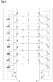
- Figure 1 shows an embodiment of the inventive light barrier arrangement of a light curtain 1 for detecting objects in a surveillance area.
- the light curtain 1 has a first housing 2 in which a number of transmitters 401, 402, 403, 404, 405, 406, 407, 408 emitting light beams 3 are arranged. In the present case, eight transmitters 401, 402, 403, 404, 405, 406, 407, 408 are provided. Of course, the light curtain 1 can also have a different number of transmitters 401, 402, 403, 404, 405, 406, 407, 408.
- the preferably identically designed transmitters 401, 402, 403, 404, 405, 406, 407, 408 are formed by light-emitting diodes that emit light in the visible or invisible range, in particular the infrared range.
- All transmitters 401, 402, 403, 404, 405, 406, 407, 408 are arranged in a linear arrangement on a circuit board 5.
- Each transmitter 401, 402, 403, 404, 405, 406, 407, 408 has a transmitting optics 6 in the form of a lens arranged in front of it for beam shaping of its light beams 3.
- a common transmitting optics 6 can be provided for several transmitters 401, 402, 403, 404, 405, 406, 407, 408.
- the operation of the transmitters 401, 402, 403, 404, 405, 406, 407, 408 is controlled by a transmitter control 7.
- the light curtain 1 further comprises a second housing 8 in which a number of receivers 10 are provided on a further circuit board 9.
- the number of receivers 10 corresponds to the number of transmitters 401, 402, 403, 404, 405, 406, 407, 408.
- the receivers 10, which are identical in the present case, are formed by photodiodes.
- Each receiver 10 is provided with a receiving optics 11 The received signals at the output of the receiver 10 are evaluated in an evaluation unit 12.
- the light curtain 1 is designed as a safety sensor and has a fail-safe structure.
- the evaluation unit 12 has a redundant two-channel structure in the form of two computer units that cyclically monitor each other.
- the two housings 2, 8 of the light curtain 1 are arranged at opposite edges of the monitoring area so that when the monitoring area is free (as in Figure 1 shown) the light beams 3 of each transmitter 401, 402, 403, 404, 405, 406, 407, 408 strike the associated receiver 10 unhindered.
- the transmitter-receiver pairs formed in this way form beam axes of the light curtain 1, with which the monitoring area is monitored.
- An object intrusion into the monitoring area is detected by the light beams 3 of at least one beam axis being at least partially interrupted.
- a threshold value evaluation of the amplitudes of the received signals of the receivers 10 is carried out in the evaluation unit 12.
- a binary object detection signal is generated in the evaluation unit 12, the switching states of which indicate whether an object is in the monitoring area or not.
- the light barrier arrangement can also consist of a number of individual light barriers whose transmitters 401, 402, 403, 404, 405, 406, 407, 408 are jointly controlled and whose receivers 10 generate received signals which are jointly evaluated.
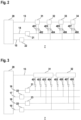
- FIG. 2 shows a first embodiment of the transmitter control 7 according to the invention.
- the transmitter control 7 comprises a control module 20 and control elements 31, 32, 33, 34 and control elements 21, 22 connected to it via control lines 13, 14, 15.
- the control module 20 consists of a microprocessor or the like, the control elements 31, 32, 33, 34 and the control elements 21, 22 advantageously consist of individual switching elements, in particular transistors.
- control elements 31, 32, 33, 34 are provided.
- a control line 13 is looped through from the control module 20 to all control elements 31, 32, 33, 34, so that the control elements 31, 32, 33, 34 form a series circuit connected to the control module 20.
- the control elements 21, 22 are connected in parallel to the control module 20 via control lines 14, 15.
- the control lines 13, 14, 15 can be designed as modulation lines.
- shift register elements can be provided for controlling the control elements 31, 32, 33, 34 or control elements 21, 22.
- the control module 20 controls the control elements 21, 22 and the control elements 31, 32, 33, 34, whereby the timing of the activation of the transmitters 401, 402, 403, 404, 405, 406, 407, 408 can be specified.
- a group of two transmitters 401, 402 and 403, 404 and 405, 406 and 407, 408 is connected to each control element 31, 32, 33, 34, so that each control element 31, 32, 33, 34 controls such a group of transmitters 401, 402 and 403, 404 and 405, 406 and 407, 408.
- control elements 21, 22 are provided, which are controlled via the control module 20.
- One control element 21, 22 is connected to only the first transmitter 401, 403, 405, 407 of all groups.
- the second control element 21, 22 is connected to the second transmitter 402, 404, 406, 408 of all groups.
- control elements 21, 22 and control elements 31, 32, 33, 34 form a matrix-shaped control circuit for the transmitters 401, 402, 403, 404, 405, 406, 407, 408, wherein each transmitter 401, 402, 403, 404, 405, 406, 407, 408 is connected to a specific, individual combination of only one drive element 31, 32, 33, 34 and only one control element 21, 22.
- a transmitter 401, 402, 403, 404, 405, 406, 407, 408 is only activated and emits light beams 3 when it is correspondingly controlled by the control element 31, 32, 33, 34 and the control element 21, 22 to which it is connected.
- the control elements 31, 32, 33, 34 and control elements 21, 22 can be used to flexibly control the timing of the activations of the individual transmitters 401, 402, 403, 404, 405, 406, 407, 408.
- the transmitters 401, 402, 403, 404, 405, 406, 407, 408 can be activated cyclically one after the other, individually or in groups.
- the transmitter control 7 can be varied such that N (where N > 2) transmitters 401, 402, 403, 404, 405, 406, 407, 408 are connected to each control element 31, 32, 33, 34 and form a group of transmitters 401, 402, 403, 404, 405, 406, 407, 408. Then N control elements are provided, to each of which a transmitter of each group is connected.
- FIG. 3 A corresponding embodiment shows Figure 3 .
- This transmitter control 7 has two control elements 31, 32, which are connected to the control module 20 via the control line 13.
- a group of four transmitters 401, 402, 403, 404 and 405, 406, 407, 408 is connected to each control element 31, 32.
- four control elements 21, 22, 23, 24 are assigned to these groups, each of which is connected to the control module 20 via a control line 16, 17, 18, 19.
- Each control element 21, 22, 23, 24 is connected to exactly one transmitter 401, 402, 403, 404, 405, 406, 407, 408 of each group.
- the individual control elements 21, 22, 23, 24 are connected to different transmitters 401, 402, 403, 404, 405, 406, 407, 408, so that with the control elements 21, 22, 23, 24 and control elements 31,32 again a matrix-shaped Arrangement of the transmitters 401, 402, 403, 404, 405, 406, 407, 408 is obtained such that each transmitter 401, 402, 403, 404, 405, 406, 407, 408 is controlled by an individual combination of exactly one control element 31, 32 and exactly one control element 21, 22, 23, 24.
- the functioning of the transmitter control 7 according to Figure 3 is analogous to the transmitter control 7 according to Figure 2 .
Landscapes
- Physics & Mathematics (AREA)
- Life Sciences & Earth Sciences (AREA)
- General Life Sciences & Earth Sciences (AREA)
- General Physics & Mathematics (AREA)
- Geophysics (AREA)
- Burglar Alarm Systems (AREA)
- Optical Communication System (AREA)
- Geophysics And Detection Of Objects (AREA)
Description
- Die Erfindung betrifft eine Lichtschrankenanordnung gemäß dem Oberbegriff des Anspruchs 1.
- Derartige Lichtschrankenanordnungen können insbesondere als Lichtvorhang ausgebildet sein. Typischerweise sind bei derartigen Lichtschrankenanordnungen mehrere Sender in einer Linearanordnung in einem Gehäuse untergebracht, wobei insbesondere die Sender auf einer gemeinsamen Leiterplatte angeordnet sind. Entsprechend sind die Empfänger in einem weiteren Gehäuse angeordnet. Diese Gehäuse befinden sich an gegenüberliegenden Rändern eines Überwachungsbereichs, innerhalb dessen Objekte erfasst werden. Bei freiem Überwachungsbereich treffen die von den Sendern emittierten Lichtstrahlen ungehindert auf die jeweils zugeordneten Empfänger. Bei einem Objekteingriff wird der Strahlengang der Lichtstrahlen wenigstens eines Senders unterbrochen. Durch eine Auswertung der Empfangssignale der Empfänger wird in einer Auswerteeinheit ein binäres Objektfeststellungssignal generiert, dessen Schaltzustände angeben, ob sich ein Objekt im Überwachungsbereich befindet oder nicht.
- Der Betrieb der Sender wird mit einer Sendersteuerung gesteuert. Typischerweise werden die Sender dadurch zyklisch einzeln nacheinander aktiviert. Typischerweise ist dabei jedem Sender eine Ansteuerschaltung als Bestandteil der Sendersteuerung zugeordnet. Dies bedingt einen unerwünscht hohen konstruktiven Aufwand.
- Die
US 5,347,135 A betrifft eine Sensoranordnung mit einer Mehrfachanordnung von Lichtstrahlen emittierenden Sendern und zugeordneten Empfängern. - Die Sender sind parallel an eine Ansteuerschaltung angeschlossen und können so einzeln aktiviert werden.
- Die
DE 40 33 234 A1 betrifft eine Schaltungsanordnung zur Ansteuerung von photoelektrischen Bauelementen einer Lichtschranke oder dergleichen, welche Bauelemente nacheinander mittels einer Umschalteinrichtung im Multiplexverfahren angesteuert werden. Weiterhin ist eine Funktionsfehler aufspürende Kontrolleinrichtung vorgesehen. Für einen einfachen Aufbau ist bei hoher Sicherheit vorgesehen, dass die photoelektrischen Bauelemente matrixförmig an den Ausgängen von Decodern angeschlossen sind, die mit voneinander unabhängigen, die Kontrolleinrichtung bildenden Prozessoren zusammenwirken. - Die
US 2006/0065818 A1 betrifft einen Lichtvorhang mit einer Mehrfachanordnung von Lichtstrahlen emittierenden Sendern und Lichtstrahlen empfangenden Empfängern. Die Sender und Empfänger werden jeweils mit einer Ansteuerschaltung, die Schieberegister aufweist, angesteuert. - Die
US 5 635 724 A betrifft eine Lichtschrankenanordnung mit einer Anordnung von Lichtstrahlen emittierenden Sendern und Lichtstrahlen empfangenden Empfängern. Die Sender werden einzeln von Transistoren gesteuert. Zwei Decoder steuern Gruppen von Transistoren, um einerseits einen Sender auszuwählen und andererseits eine Gruppe auszuwählen. - Der Erfindung liegt die Aufgabe zugrunde, eine Lichtschrankenanordnung bereitzustellen, mittels dieser bei geringem konstruktivem Aufwand eine flexible Ansteuerung der Sender ermöglicht wird.
- Zur Lösung dieser Aufgabe sind die Merkmale des Anspruchs 1 vorgesehen. Vorteilhafte Ausführungsformen und zweckmäßige Weiterbildungen der Erfindung sind in den abhängigen Ansprüchen beschrieben.
- Die Erfindung betrifft eine Lichtschrankenanordnung zur Erfassung von Objekten in einem Überwachungsbereich mit einer Anordnung von Lichtstrahlen emittierenden Sendern und einer Anzahl von den Sendern zugeordneten Empfängern. Mit einer Sendersteuerung ist der Betrieb der Sender gesteuert. Die Sendersteuerung weist eine Anzahl von Ansteuerelementen auf, wobei mit jedem Ansteuerelement eine Gruppe von Sendern angesteuert ist. Die Sendersteuerung weist weiter eine Anzahl von Steuerelementen auf, wobei mit jedem Steuerelement jeweils nur ein Sender einer Gruppe angesteuert ist. Ein Sender emittiert nur dann Lichtstrahlen, wenn dieser durch das ihm zugeordnete Ansteuerelement und durch das ihm zugeordnete Steuerelement aktiviert ist. Die Ansteuerelemente sind in geringen Abständen zu den jeweils zugeordneten Sendern angeordnet. Die Steuerelemente sind in großen Abständen zu den Sendern der einzelnen Gruppen angeordnet. Dabei sind die Sender auf einer Leiterplatte angeordnet und die Ansteuerelemente sind mit den Sendern auf der Leiterplatte angeordnet. Alternativ sind jeweils auf einer Leiterplatte die Sender einer Gruppe und das zugeordnete Ansteuerelement angeordnet, wogegen die Steuerelemente hiervon räumlich getrennt angeordnet sind.
- Die Sendersteuerung der erfindungsgemäßen Lichtschrankenanordnung weist einen kompakten, modularen Aufbau auf, mit der die einzelnen Sender derart angesteuert werden können, dass das Zeitverhalten der Aktivierung der einzelnen Sender flexibel vorgesehen werden kann.
- Mit der erfindungsgemäßen Sendersteuerung können beispielsweise die Sender der Lichtschrankenanordnung zyklisch einzeln nacheinander aktiviert werden. Alternativ können mehrere Sender auch gleichzeitig aktiviert werden, wodurch die Zykluszeit der Aktivierung der Sender verkürzt werden kann. Dabei werden vorzugsweise die zwei benachbarten Sender gleichzeitig aktiviert, wodurch gegenseitige Beeinflussungen von Sendern auf einfache Weise vermieden werden können.
- Ein wesentlicher Vorteil der erfindungsgemäßen Sendersteuerung ist deren konstruktiv einfacher Aufbau.
- Dabei ist vorteilhaft, dass die Sender in Gruppen zusammengefasst sind und alle Sender einer Gruppe von nur einem Ansteuerelement angesteuert sind. Dies stellt eine erhebliche schaltungstechnische Vereinfachung gegenüber bekannten Lichtschrankenanordnungen dar, wo jedem Sender ein separates Ansteuerelement zugeordnet ist.
- Erfindungsgemäß ist eine Anzahl von Steuerelementen vorgesehen, mittels derer, bevorzugt für alle Gruppen von Sendern, jeweils genau ein Sender einer Gruppe angesteuert wird.
- Durch die so in den Ansteuerelementen und den Steuerelementen gebildete matrixförmige Ansteuerung der Sender der Lichtschrankenanordnung können diese einzeln oder zu mehreren gleichzeitig zu vorgegebenen Zeiten aktiviert werden, wodurch mit einer geringen Anzahl von Bauteilen die Sender flexibel aktiviert werden können.
- Gemäß einer vorteilhaften Ausgestaltung sind mehrere identische Ansteuerelemente vorgesehen. Allen Ansteuerelementen ist dieselbe Anzahl von Sendern als Gruppe zugeordnet.
- Dann ist es vorteilhaft, dass jedes Steuerelement in allen Gruppen jeweils einen Sender ansteuert.
- Dabei entspricht die Anzahl der Steuerelemente der Anzahl der Sender einer einem Ansteuerelement zugeordneten Gruppe.
- So kann mit den Steuerelementen und Ansteuerelementen auf eine besonders einfache Weise eine gezielte Einzelaktivierung von Sendern erfolgen.
- Besonders vorteilhaft weist die Sendersteuerung ein Steuermodul auf, mittels dessen der Betrieb der Ansteuerelemente und der Steuerelemente gesteuert ist.
- Dabei sind bevorzugt zur Ansteuerung der Steuerelemente und/oder der Ansteuerelemente Schieberegisterelemente und/oder eine Modulationsleitung vorgesehen.
- Auf diese Weise kann das Zeitverhalten der Aktivierungen der Sender besonders einfach vorgegeben werden.
- Gemäß einer konstruktiv besonders vorteilhaften Ausführungsform weist jedes Ansteuerelement ein Schaltelement zur Ansteuerung der jeweiligen Gruppe von Sendern auf.
- Weiterhin weist jedes Steuerelement ein Schaltelement zur Ansteuerung jeweils eines Senders seiner Gruppe auf.
- Dabei sind die Schaltelemente jeweils von einem Transistor gebildet.
- Die Erfassung von Objekten im Überwachungsbereich erfolgt bei der erfindungsgemäßen Lichtschrankenanordnung generell nach dem Lichtschrankenprinzip. Die Sender einerseits und die Empfänger andererseits sind an gegenüberliegenden Rändern des Überwachungsbereichs so angeordnet, dass bei freiem Überwachungsbereich die Lichtstrahlen der Sender ungehindert auf dessen zugeordneten Empfänger treffen. Bei einem Objekteingriff in den Überwachungsbereich wird wenigstens die Strahlachse der Lichtstrahlen eines der Sender unterbrochen, was in einer Auswerteeinheit durch eine Amplitudenbewertung der Empfangssignale festgestellt wird.
- Erfindungsgemäß sind die Ansteuerelemente in geringen Abständen zu den jeweils zugeordneten Sendern angeordnet.
- Im Gegensatz hierzu sind die Steuerelemente in großen Abständen zu den Sendern der einzelnen Gruppen angeordnet.
- Typischerweise befinden sich die Ansteuerelemente zum jeweiligen Sender in einem geringen Abstand von einem oder einigen wenigen Zentimeter, während die Steuerelemente in Abständen von mehr als 10 Zentimeter oder sogar bis zu einigen Metern von den Sendern entfernt sein können.
- Erfindungsgemäß sind die Sender auf einer Leiterplatte angeordnet.
- Die Ansteuerelemente sind mit den Sendern auf der Leiterplatte angeordnet, wogegen die Steuerelemente hiervon räumlich getrennt angeordnet sind.
- Alternativ sind die Sender auf mehreren Leiterplatten verteilt angeordnet, wobei auf einer Leiterplatte die Sender einer Gruppe und das zugeordnete Ansteuerelement angeordnet sind.
- Vorteilhaft sind die Sender von Leuchtdioden gebildet, die Lichtstrahlen im sichtbaren oder unsichtbaren Wellenlängenbereich emittieren.
- Die Leuchtdioden bilden kostengünstige Standardbauteile, so dass damit geringe Herstellkosten der Lichtschrankenanordnung realisiert werden können.
- Zur Strahlformung der Lichtstrahlen ist jedem Sender eine Sendeoptik zugeordnet.
- Gemäß einer ersten Variante ist jedem Sender eine separate Sendeoptik zugeordnet.
- Gemäß einer zweiten Variante sind jeweils mehrere Sender zu Modulen zusammengefasst, welchen eine gemeinsame Sendeoptik zugeordnet ist.
- Generell ist es auch möglich auf Sendeoptiken völlig zu verzichten, insbesondere dann, wenn Sender bildende Leuchtdioden eine integrierte Optik aufweisen.
- Besonders vorteilhaft ist die Lichtschrankenanordnung als Lichtvorhang ausgebildet. Die Sender mit der Sendersteuerung sind dann in einem ersten Gehäuse, die Empfänger und eine diesen zugeordneten Auswerteeinheit sind in einem zweiten Gehäuse integriert. Mit der Auswerteeinheit wird in Abhängigkeit der Empfangssignale der Empfänger ein binäres Objektfeststellungssignal generiert, dessen Schaltzustände angeben, ob sich ein Objekt im Überwachungsbereich befindet oder nicht.
- Die Aktivierung der Sender erfolgt mit der Sendersteuerung derart, dass die Sender einzeln oder in Gruppen zyklisch nacheinander aktiviert werden. Die Empfänger können dauerhaft aktiviert sein. Alternativ werden durch eine optische Synchronisation über die Lichtstrahlen der Sender die Sender und die diesen zugeordneten Empfänger gleichzeitig aktiviert.
- Weiter vorteilhaft ist die Lichtschrankenanordnung als Sicherheitssensor ausgebildet.
- Damit kann die Lichtschrankenanordnung in sicherheitstechnischen Anwendungen, insbesondere im Bereich des Personenschutzes, eingesetzt werden. Hierzu weist die Lichtschrankenanordnung einen fehlersicheren Aufbau auf, was insbesondere dadurch realisiert wird, dass die Auswerteeinheit der Lichtschrankenanordnung einen redundanten Aufbau aufweist, insbesondere in Form zweier sich gegenseitig zyklisch überwachenden Rechnereinheiten.
- Die Erfindung wird im Folgenden anhand der Zeichnungen erläutert. Es zeigen:
- Figur 1:
- Schematische Darstellung eines Ausführungsbeispiels der erfindungsgemäßen Lichtstrahlenanordnung in Form eines Lichtvorhangs.
- Figur 2:
- Erstes Ausführungsbeispiel einer Sendersteuerung für den Lichtvorhang gemäß
Figur 1 . - Figur 3:
- Zweites Ausführungsbeispiel einer Sendersteuerung für den Lichtvorhang gemäß
Figur 1 . -
Figur 1 zeigt ein Ausführungsbeispiel der erfindungsgemäßen Lichtschrankenanordnung eines Lichtvorhangs 1 zur Erfassung von Objekten in einem Überwachungsbereich. - Der Lichtvorhang 1 weist ein erstes Gehäuse 2 auf, in dem eine Anzahl von Lichtstrahlen 3 emittierenden Sendern 401, 402, 403, 404, 405, 406, 407, 408 angeordnet ist. Im vorliegenden Fall sind acht Sender 401, 402, 403, 404, 405, 406, 407, 408 vorgesehen. Natürlich kann der Lichtvorhang 1 auch eine andere Anzahl von Sendern 401, 402, 403, 404, 405, 406, 407, 408 aufweisen. Die vorzugsweise identisch ausgebildeten Sender 401, 402, 403, 404, 405, 406, 407, 408 sind von Leuchtdioden gebildet, die Licht im sichtbaren oder unsichtbaren Bereich, insbesondere Infrarot-Bereich, emittieren.
- Alle Sender 401, 402, 403, 404, 405, 406, 407, 408 sind in einer Linearanordnung auf einer Leiterplatte 5 angeordnet. Jedem Sender 401, 402, 403, 404, 405, 406, 407, 408 ist zur Strahlformung deren Lichtstrahlen 3 eine Sendeoptik 6 in Form einer Linse vorgeordnet. Alternativ können für mehrere Sender 401, 402, 403, 404, 405, 406, 407, 408 jeweils eine gemeinsame Sendeoptik 6 vorgesehen sein.
- Der Betrieb der Sender 401, 402, 403, 404, 405, 406, 407, 408 wird mit einer Sendersteuerung 7 gesteuert.
- Der Lichtvorhang 1 umfasst weiterhin ein zweites Gehäuse 8, in dem auf einer weiteren Leiterpatte 9 eine Anzahl von Empfängern 10 vorgesehen ist. Die Anzahl der Empfänger 10 entspricht der Anzahl der Sender 401, 402, 403, 404, 405, 406, 407, 408. Die im vorliegenden Fall identisch ausgebildeten Empfänger 10 sind von Photodioden gebildet. Jedem Empfänger 10 ist eine Empfangsoptik 11 zugeordnet. Die am Ausgang der Empfänger 10 anstehenden Empfangssignale werden in einer Auswerteeinheit 12 ausgewertet.
- Der Lichtvorhang 1 ist im vorliegenden Fall als Sicherheitssensor ausgebildet und weist einen fehlersichereren Aufbau auf. Hierzu ist die Auswerteeinheit 12 redundant zweikanalig aufgebaut, in Form zweier sich gegenseitig zyklisch überwachenden Rechnereinheiten.
- Die beiden Gehäuse 2, 8 des Lichtvorhangs 1 sind in gegenüberliegenden Rändem des Überwachungsbereichs so angeordnet, dass bei freiem Überwachungsbereich (wie in
Figur 1 dargestellt) die Lichtstrahlen 3 jedes Senders 401, 402, 403, 404, 405, 406, 407, 408 ungehindert auf den zugeordneten Empfänger 10 treffen. Die so gebildeten Sender-Empfängerpaare bilden Strahlachsen des Lichtvorhangs 1, mit welchen der Überwachungsbereich überwacht wird. Ein Objekteingriff in den Überwachungsbereich wird dadurch erfasst, dass die Lichtstrahlen 3 wenigstens einer Strahlachse zumindest teilweise unterbrochen sind. Hierzu erfolgt in der Auswerteeinheit 12 eine Schwellwertbewertung der Amplituden der Empfangssignale der Empfänger 10. Abhängig hiervon wird in der Auswerteeinheit 12 binäres Objektfeststellungssignal generiert, dessen Schaltzustände angeben, ob sich ein Objekt im Überwachungsbereich befindet oder nicht. - Anstelle der Ausbildung in Form eines Lichtvorhangs 1 kann die Lichtschrankenanordnung auch aus einer Anzahl von einzelnen Lichtschranken bestehen, deren Sender 401, 402, 403, 404, 405, 406, 407, 408 gemeinsam gesteuert und deren Empfänger 10 Empfangssignale generieren, die gemeinsam ausgewertet werden.
-
Figur 2 zeigt ein erstes Ausführungsbeispiel der erfindungsgemäßen Sendersteuerung 7. Die Sendersteuerung 7 umfasst ein Steuermodul 20 und an diese über Steuerleitungen 13, 14, 15 angeschlossene Ansteuerelemente 31, 32, 33 ,34 und Steuerelemente 21, 22. - Das Steuermodul 20 besteht aus einem Mikroprozessor oder dergleichen, die Ansteuerelemente 31, 32, 33, 34 und die Steuerelemente 21,22 bestehen vorteilhaft aus einzelnen Schaltelementen, insbesondere Transistoren.
- Bei dieser Ausführungsform sind vier identische Ansteuerelemente 31, 32, 33, 34 vorgesehen. Eine Steuerleitung 13 ist vom Steuermodul 20 ausgehend zu allen Ansteuerelemente 31, 32, 33, 34 durchgeschleift, so dass die Ansteuerelemente 31, 32, 33, 34 eine an das Steuermodul 20 angeschlossene Reihenschaltung bilden. Die Steuerelemente 21, 22 sind über Steuerleitungen 14, 15 parallel an das Steuermodul 20 angeschlossen. Die Steuerleitungen 13, 14, 15 können als Modulationsleitungen ausgebildet sein. Alternativ können Schieberegisterelemente zur Ansteuerung der Ansteuerelemente 31, 32, 33, 34 beziehungsweise Steuerelemente 21, 22 vorgesehen sein.
- Mit dem Steuermodul 20 werden die Steuerelemente 21, 22 und Ansteuerelemente 31, 32, 33, 34 angesteuert, wodurch das Zeitverhalten der Aktivierung der Sender 401, 402, 403, 404, 405, 406, 407, 408 vorgebbar ist.
- Wie
Figur 2 zeigt, ist an jedes Ansteuerelement 31, 32, 33, 34 eine Gruppe von zwei Sendern 401, 402 und 403, 404 und 405, 406 und 407, 408 angeschlossen, so dass jedes Ansteuerelement 31, 32, 33, 34 eine solche Gruppe von Sendern 401, 402 und 403, 404 und 405, 406 und 407, 408 ansteuert. - Weiterhin sind zwei Steuerelemente 21, 22 vorgesehen, die über das Steuermodul 20 gesteuert werden. Dabei ist ein Steuerelement 21, 22 mit jeweils nur dem ersten Sender 401, 403, 405, 407 aller Gruppen verbunden. Das zweite Steuerelement 21, 22 ist mit jeweils dem zweiten Sender 402, 404, 406, 408 aller Gruppen verbunden.
- Die Steuerelemente 21, 22 und Ansteuerelemente 31, 32, 33, 34 bilden eine matrixförmige Ansteuerschaltung für die Sender 401, 402, 403, 404, 405, 406, 407, 408, wobei jeder Sender 401, 402, 403, 404, 405, 406, 407, 408 mit einer spezifischen, individuellen Kombination nur eines Ansteuerelements 31, 32, 33, 34 und nur eines Steuerelements 21, 22 verbunden ist.
- Ein Sender 401, 402, 403, 404, 405, 406, 407, 408 ist nur dann aktiviert und sendet Lichtstrahlen 3 aus, wenn er von dem Ansteuerelement 31, 32, 33, 34 und dem Steuerelement 21, 22, an welchem dieser angeschlossen ist, entsprechend angesteuert wird.
- Durch die Ansteuerelemente 31, 32, 33, 34 und Steuerelemente 21, 22 kann das Zeitverhalten der Aktivierungen der einzelnen Sender 401, 402, 403, 404, 405, 406, 407, 408 flexibel gesteuert werden. Insbesondere können die Sender 401, 402, 403, 404, 405, 406, 407, 408 einzeln oder in Gruppen zyklisch nacheinander aktiviert werden.
- Generell kann die Sendersteuerung 7 dahingehend variiert werden, dass an jedes Ansteuerelement 31, 32, 33, 34 N (wobei N > 2) Sender 401, 402, 403, 404, 405, 406, 407, 408 angeschlossen sind und eine Gruppe von Sendern 401, 402, 403, 404, 405, 406, 407, 408 bilden. Dann sind N Steuerelemente vorgesehen, mit welchen jeweils ein Sender jeder Gruppe verbunden ist.
- Ein entsprechendes Ausführungsbeispiel zeigt
Figur 3 . Diese Sendersteuerung 7 weist zwei Ansteuerelemente 31, 32 auf, die über die Steuerleitung 13 mit dem Steuermodul 20 verbunden sind. In jedes Ansteuerelement 31, 32 ist eine Gruppe von vier Sendern 401, 402, 403, 404 und 405, 406, 407, 408 angeschlossen. Dementsprechend sind diesen Gruppen vier Steuerelemente 21, 22, 23, 24 zugeordnet, die jeweils über eine Steuerleitung 16, 17, 18, 19 mit dem Steuermodul 20 verbunden sind. Jedes Steuerelement 21, 22, 23, 24 ist mit genau einem Sender 401, 402, 403, 404, 405, 406, 407, 408 jeder Gruppe verbunden. Dabei sind die einzelnen Steuerelemente 21, 22, 23, 24 mit jeweils verschiedenen Sendern 401, 402, 403, 404, 405, 406, 407, 408 verbunden, so dass mit den Steuerelementen 21, 22, 23, 24 und Ansteuerelementen 31,32 wieder eine matrixförmige Anordnung der Sender 401, 402, 403, 404, 405, 406, 407, 408 derart erhalten wird, dass jeder Sender 401, 402, 403, 404, 405, 406, 407, 408 von einer individuellen Kombination genau eines Ansteuerelements 31, 32 und genau eines Steuerelements 21, 22, 23, 24 gesteuert wird. Die Funktionsweise der Sendersteuerung 7 gemäßFigur 3 ist analog zur Sendersteuerung 7 gemäßFigur 2 . -
- (1)
- Lichtvorhang
- (2)
- Gehäuse
- (3)
- Lichtstrahlen
- (5)
- Leiterplatte
- (6)
- Sendeoptik
- (7)
- Sendersteuerung
- (8)
- Gehäuse
- (9)
- Leiterplatte
- (10)
- Empfänger
- (11)
- Empfangsoptik
- (12)
- Auswerteeinheit
- (13)
- Steuerleitung
- (14)
- Steuerleitung
- (15)
- Steuerleitung
- (16)
- Steuerleitung
- (17)
- Steuerleitung
- (18)
- Steuerleitung
- (19)
- Steuerleitung
- (20)
- Steuermodul
- (21)
- Steuerelement
- (22)
- Steuerelement
- (23)
- Steuerelement
- (24)
- Steuerelement
- (31)
- Ansteuerelement
- (32)
- Ansteuerelement
- (33)
- Ansteuerelement
- (34)
- Ansteuerelement
- (401)
- Sender
- (402)
- Sender
- (403)
- Sender
- (404)
- Sender
- (405)
- Sender
- (406)
- Sender
- (407)
- Sender
- (408)
- Sender
Claims (12)
- Lichtschrankenanordnung zur Erfassung von Objekten in einem Überwachungsbereich mit einer Anordnung von Lichtstrahlen (3) emittierenden Sendern (401, 402, 403, 404, 405, 406, 407, 408) und einer Anzahl von den Sendern (401, 402, 403, 404, 405, 406, 407, 408) zugeordneten Empfängern (10), mit einer Sendersteuerung (7), mit der der Betrieb der Sender (401, 402, 403, 404, 405, 406, 407, 408) gesteuert ist, wobei die Sendersteuerung (7) eine Anzahl von Ansteuerelementen (31, 32, 33, 34) aufweist, wobei mit jedem Ansteuerelement (31, 32, 33, 34) eine Gruppe von Sendern (401, 402 und 403, 404 und 405, 406 und 407, 408) angesteuert ist, und mit einer Anzahl von Steuerelementen (21, 22, 23, 24), wobei mit jedem Steuerelement (21, 22, 23, 24) jeweils nur ein Sender (401, 402, 403, 404, 405, 406, 407, 408) einer Gruppe angesteuert ist, wobei ein Sender (401, 402, 403, 404, 405, 406, 407, 408) nur dann Lichtstrahlen (3) emittiert, wenn dieser durch das ihm zugeordnete Ansteuerelement (31, 32, 33, 34) und durch das ihm zugeordnete Steuerelement (21, 22, 23, 24) aktiviert ist, die Ansteuerelemente (31, 32, 33, 34) in geringen Abständen zu den jeweils zugeordneten Sendern (401, 402, 403, 404, 405, 406, 407, 408) angeordnet sind, und die Steuerelemente (21, 22, 23, 24) in großen Abständen zu den Sendern (401, 402, 403, 404, 405, 406, 407, 408) der einzelnen Gruppen angeordnet sind, wobei die Sender (401, 402, 403, 404, 405, 406, 407, 408) auf einer Leiterplatte angeordnet sind und die Ansteuerelemente (31, 32, 33, 34) mit den Sendern (401, 402, 403, 404, 405, 406, 407, 408) auf der Leiterplatte angeordnet sind oder jeweils auf einer Leiterplatte die Sender einer Gruppe und das zugeordnete Ansteuerelement (31, 32, 33, 34) angeordnet sind, wogegen die Steuerelemente (21, 22, 23, 24) hiervon räumlich getrennt angeordnet sind.
- Lichtschrankenanordnung nach Anspruch 1, dadurch gekennzeichnet, dass mehrere identische Ansteuerelemente (31, 32, 33, 34) vorgesehen sind, wobei allen Ansteuerelementen (31, 32, 33, 34) dieselbe Anzahl von Sendern (401, 402, 403, 404, 405, 406, 407, 408) als Gruppe zugeordnet ist.
- Lichtschrankenanordnung nach einem der Ansprüche 1 oder 2, dadurch gekennzeichnet, dass jedes Steuerelement (21, 22, 23, 24) in allen Gruppen jeweils einen Sender (401, 402, 403, 404, 405, 406, 407, 408) ansteuert.
- Lichtschrankenanordnung nach Anspruch 3, dadurch gekennzeichnet, dass die Anzahl der Steuerelemente (21, 22, 23, 24) der Anzahl der Sender (401, 402, 403, 404, 405, 406, 407, 408) einer einem Ansteuerelement (31, 32, 33, 34) zugeordneten Gruppe entspricht.
- Lichtschrankenanordnung nach einem der Ansprüche 1 - 4, dadurch gekennzeichnet, dass die Sendersteuerung (7) ein Steuermodul (20) aufweist, mittels dessen der Betrieb der Ansteuerelemente (31, 32, 33, 34) und der Steuerelemente (21, 22, 23, 24) gesteuert ist.
- Lichtschrankenanordnung nach einem der Ansprüche 1 - 5, dadurch gekennzeichnet, dass zur Ansteuerung der Steuerelemente (21, 22, 23, 24) und/oder der Ansteuerelemente (31, 32, 33, 34) Schieberegisterelemente und/oder eine Modulationsleitung vorgesehen sind.
- Lichtschrankenanordnung nach einem der Ansprüche 1 - 6, dadurch gekennzeichnet, dass jedes Ansteuerelement (31, 32, 33, 34) ein Schaltelement zur Ansteuerung der jeweiligen Gruppe von Sendern (401, 402, 403, 404, 405, 406, 407, 408) aufweist.
- Lichtschrankenanordnung nach einem der Ansprüche 1 - 7, dadurch gekennzeichnet, dass jedes Steuerelement (21, 22, 23, 24) ein Schaltelement zur Ansteuerung jeweils eines Senders (401, 402, 403, 404, 405, 406, 407, 408) seiner Gruppe aufweist.
- Lichtschrankenanordnung nach einem der Ansprüche 1 bis 8, dadurch gekennzeichnet, dass die Sender (401, 402, 403, 404, 405, 406, 407, 408) von Leuchtdioden gebildet sind, die Lichtstrahlen (3) im sichtbaren oder unsichtbaren Wellenlängenbereich emittieren.
- Lichtschrankenanordnung nach einem der Ansprüche 1 bis 9, dadurch gekennzeichnet, dass jedem Sender (401, 402, 403, 404, 405, 406, 407, 408) eine Sendeoptik (6) zugeordnet ist, wobei jedem Sender (401, 402, 403, 404, 405, 406, 407, 408) eine separate Sendeoptik (6) zugeordnet ist, oder dass jeweils mehrere Sender (401, 402, 403, 404, 405, 406, 407, 408) zu Modulen zusammengefasst sind, welchen eine gemeinsame Sendeoptik (6) zugeordnet ist.
- Lichtschrankenanordnung nach einem der Ansprüche 1 bis 10, dadurch gekennzeichnet, dass diese als Lichtvorhang (1) ausgebildet ist.
- Lichtschrankenanordnung nach einem der Ansprüche 1 bis 11, dadurch gekennzeichnet, dass diese als Sicherheitssensor ausgebildet ist.
Applications Claiming Priority (1)
| Application Number | Priority Date | Filing Date | Title |
|---|---|---|---|
| DE202018105747.2U DE202018105747U1 (de) | 2018-10-08 | 2018-10-08 | Lichtschrankenanordnung |
Publications (2)
| Publication Number | Publication Date |
|---|---|
| EP3637155A1 EP3637155A1 (de) | 2020-04-15 |
| EP3637155B1 true EP3637155B1 (de) | 2025-01-01 |
Family
ID=67614420
Family Applications (1)
| Application Number | Title | Priority Date | Filing Date |
|---|---|---|---|
| EP19190638.7A Active EP3637155B1 (de) | 2018-10-08 | 2019-08-08 | Lichtschrankenanordnung |
Country Status (2)
| Country | Link |
|---|---|
| EP (1) | EP3637155B1 (de) |
| DE (1) | DE202018105747U1 (de) |
Citations (1)
| Publication number | Priority date | Publication date | Assignee | Title |
|---|---|---|---|---|
| US5635724A (en) * | 1995-06-07 | 1997-06-03 | Intecolor | Method and apparatus for detecting the location of an object on a surface |
Family Cites Families (7)
| Publication number | Priority date | Publication date | Assignee | Title |
|---|---|---|---|---|
| DE4033234A1 (de) * | 1990-10-19 | 1992-04-23 | Datalogic Optic Electronics Pr | Sicherheitslichtgitter |
| US5220177A (en) * | 1991-06-24 | 1993-06-15 | Harris Instrument Corporation | Method and apparatus for edge detection and location |
| US5347135A (en) * | 1991-06-24 | 1994-09-13 | Harris Instrument Corporation | Method and apparatus employing a linear array IR region radiation devices for locating the position of conveyor transported products |
| JP3788502B2 (ja) * | 2000-08-11 | 2006-06-21 | オムロン株式会社 | 光カーテン創成装置 |
| DE10212432A1 (de) * | 2002-03-21 | 2003-10-16 | Leuze Electronic Gmbh & Co | Optischer Sensor |
| JP2004328545A (ja) * | 2003-04-25 | 2004-11-18 | Sharp Corp | デコード回路ならびにそれを用いるディスク記録/再生装置の受光アンプ回路および光学ピックアップ |
| DE102005046478B4 (de) * | 2004-09-30 | 2019-03-14 | Omron Corp. | Photoelektrischer Mehrstrahl-Sensor |
-
2018
- 2018-10-08 DE DE202018105747.2U patent/DE202018105747U1/de active Active
-
2019
- 2019-08-08 EP EP19190638.7A patent/EP3637155B1/de active Active
Patent Citations (1)
| Publication number | Priority date | Publication date | Assignee | Title |
|---|---|---|---|---|
| US5635724A (en) * | 1995-06-07 | 1997-06-03 | Intecolor | Method and apparatus for detecting the location of an object on a surface |
Also Published As
| Publication number | Publication date |
|---|---|
| DE202018105747U1 (de) | 2020-01-09 |
| EP3637155A1 (de) | 2020-04-15 |
Similar Documents
| Publication | Publication Date | Title |
|---|---|---|
| EP2147338B1 (de) | Optoelektronischer sensor zum absichern eines gefahrenbereichs | |
| EP1933174B1 (de) | Lichtgitter | |
| DE102012101369B4 (de) | Lichtvorhang | |
| DE102012101368B4 (de) | Lichtvorhang | |
| EP2071363B1 (de) | Lichtgitter und Verfahren zu dessen Betrieb | |
| EP3822666B1 (de) | Lichtschrankenanordnung | |
| DE102012101431B4 (de) | Sensoranordnung | |
| DE102013106785B4 (de) | Verfahren zur Synchronisation eines Lichtgitters und auf diesem Verfahren beruhendes Lichtgitter | |
| DE102007043378B4 (de) | Lichtgitter | |
| DE102018117878B4 (de) | Sicherheitslichtgitter | |
| DE102005050979B4 (de) | Verfahren zur Funktionsüberprüfung einer Sicherheitsausgangsschaltung eines optischen Sensors | |
| EP2502098B1 (de) | Lichtvorhang | |
| EP2672296B1 (de) | Lichtvorhang | |
| EP3637155B1 (de) | Lichtschrankenanordnung | |
| DE202007007290U1 (de) | Optoelektronische Sensoranordnung | |
| DE10120940B4 (de) | Sicherheitseinrichtung zur Überwachung von mindestens zwei aneinandergrenzenden Ebenen durch Lichtschrankenanordnungen, insbesondere Lichtvorhänge | |
| DE102008022791B4 (de) | Lichtvorhang | |
| EP4092449B1 (de) | Lichtschrankenanordnung und verfahren zur erfassung von objekten in einem überwachungsbereich | |
| EP2259093B1 (de) | Optoelektronische Sensoranordnung und Verfahren zum Betrieb einer solchen | |
| DE202018104258U1 (de) | Sicherheitslichtgitter | |
| DE19861128B4 (de) | Optischer Türwächter | |
| EP1480060B1 (de) | Optischer Sensor | |
| EP4279792B1 (de) | Lichtvorhang | |
| EP4411426B1 (de) | Lichtvorhang | |
| EP3770647A1 (de) | Lichtschrankenanordnung und verfahren zur justage einer lichtschrankenanordnung |
Legal Events
| Date | Code | Title | Description |
|---|---|---|---|
| PUAI | Public reference made under article 153(3) epc to a published international application that has entered the european phase |
Free format text: ORIGINAL CODE: 0009012 |
|
| STAA | Information on the status of an ep patent application or granted ep patent |
Free format text: STATUS: THE APPLICATION HAS BEEN PUBLISHED |
|
| AK | Designated contracting states |
Kind code of ref document: A1 Designated state(s): AL AT BE BG CH CY CZ DE DK EE ES FI FR GB GR HR HU IE IS IT LI LT LU LV MC MK MT NL NO PL PT RO RS SE SI SK SM TR |
|
| AX | Request for extension of the european patent |
Extension state: BA ME |
|
| STAA | Information on the status of an ep patent application or granted ep patent |
Free format text: STATUS: REQUEST FOR EXAMINATION WAS MADE |
|
| 17P | Request for examination filed |
Effective date: 20200415 |
|
| RBV | Designated contracting states (corrected) |
Designated state(s): AL AT BE BG CH CY CZ DE DK EE ES FI FR GB GR HR HU IE IS IT LI LT LU LV MC MK MT NL NO PL PT RO RS SE SI SK SM TR |
|
| STAA | Information on the status of an ep patent application or granted ep patent |
Free format text: STATUS: EXAMINATION IS IN PROGRESS |
|
| 17Q | First examination report despatched |
Effective date: 20220627 |
|
| P01 | Opt-out of the competence of the unified patent court (upc) registered |
Effective date: 20240423 |
|
| GRAP | Despatch of communication of intention to grant a patent |
Free format text: ORIGINAL CODE: EPIDOSNIGR1 |
|
| STAA | Information on the status of an ep patent application or granted ep patent |
Free format text: STATUS: GRANT OF PATENT IS INTENDED |
|
| GRAS | Grant fee paid |
Free format text: ORIGINAL CODE: EPIDOSNIGR3 |
|
| INTG | Intention to grant announced |
Effective date: 20241024 |
|
| GRAA | (expected) grant |
Free format text: ORIGINAL CODE: 0009210 |
|
| STAA | Information on the status of an ep patent application or granted ep patent |
Free format text: STATUS: THE PATENT HAS BEEN GRANTED |
|
| AK | Designated contracting states |
Kind code of ref document: B1 Designated state(s): AL AT BE BG CH CY CZ DE DK EE ES FI FR GB GR HR HU IE IS IT LI LT LU LV MC MK MT NL NO PL PT RO RS SE SI SK SM TR |
|
| REG | Reference to a national code |
Ref country code: GB Ref legal event code: FG4D Free format text: NOT ENGLISH |
|
| REG | Reference to a national code |
Ref country code: CH Ref legal event code: EP |
|
| REG | Reference to a national code |
Ref country code: DE Ref legal event code: R096 Ref document number: 502019012722 Country of ref document: DE |
|
| REG | Reference to a national code |
Ref country code: IE Ref legal event code: FG4D Free format text: LANGUAGE OF EP DOCUMENT: GERMAN |
|
| REG | Reference to a national code |
Ref country code: LT Ref legal event code: MG9D |
|
| REG | Reference to a national code |
Ref country code: NL Ref legal event code: MP Effective date: 20250101 |
|
| PG25 | Lapsed in a contracting state [announced via postgrant information from national office to epo] |
Ref country code: NL Free format text: LAPSE BECAUSE OF FAILURE TO SUBMIT A TRANSLATION OF THE DESCRIPTION OR TO PAY THE FEE WITHIN THE PRESCRIBED TIME-LIMIT Effective date: 20250101 |
|
| PG25 | Lapsed in a contracting state [announced via postgrant information from national office to epo] |
Ref country code: FI Free format text: LAPSE BECAUSE OF FAILURE TO SUBMIT A TRANSLATION OF THE DESCRIPTION OR TO PAY THE FEE WITHIN THE PRESCRIBED TIME-LIMIT Effective date: 20250101 |
|
| PG25 | Lapsed in a contracting state [announced via postgrant information from national office to epo] |
Ref country code: PL Free format text: LAPSE BECAUSE OF FAILURE TO SUBMIT A TRANSLATION OF THE DESCRIPTION OR TO PAY THE FEE WITHIN THE PRESCRIBED TIME-LIMIT Effective date: 20250101 |
|
| PG25 | Lapsed in a contracting state [announced via postgrant information from national office to epo] |
Ref country code: ES Free format text: LAPSE BECAUSE OF FAILURE TO SUBMIT A TRANSLATION OF THE DESCRIPTION OR TO PAY THE FEE WITHIN THE PRESCRIBED TIME-LIMIT Effective date: 20250101 |
|
| PG25 | Lapsed in a contracting state [announced via postgrant information from national office to epo] |
Ref country code: IS Free format text: LAPSE BECAUSE OF FAILURE TO SUBMIT A TRANSLATION OF THE DESCRIPTION OR TO PAY THE FEE WITHIN THE PRESCRIBED TIME-LIMIT Effective date: 20250501 Ref country code: NO Free format text: LAPSE BECAUSE OF FAILURE TO SUBMIT A TRANSLATION OF THE DESCRIPTION OR TO PAY THE FEE WITHIN THE PRESCRIBED TIME-LIMIT Effective date: 20250401 |
|
| PG25 | Lapsed in a contracting state [announced via postgrant information from national office to epo] |
Ref country code: HR Free format text: LAPSE BECAUSE OF FAILURE TO SUBMIT A TRANSLATION OF THE DESCRIPTION OR TO PAY THE FEE WITHIN THE PRESCRIBED TIME-LIMIT Effective date: 20250101 |
|
| PG25 | Lapsed in a contracting state [announced via postgrant information from national office to epo] |
Ref country code: PT Free format text: LAPSE BECAUSE OF FAILURE TO SUBMIT A TRANSLATION OF THE DESCRIPTION OR TO PAY THE FEE WITHIN THE PRESCRIBED TIME-LIMIT Effective date: 20250502 Ref country code: LV Free format text: LAPSE BECAUSE OF FAILURE TO SUBMIT A TRANSLATION OF THE DESCRIPTION OR TO PAY THE FEE WITHIN THE PRESCRIBED TIME-LIMIT Effective date: 20250101 |
|
| PG25 | Lapsed in a contracting state [announced via postgrant information from national office to epo] |
Ref country code: BG Free format text: LAPSE BECAUSE OF FAILURE TO SUBMIT A TRANSLATION OF THE DESCRIPTION OR TO PAY THE FEE WITHIN THE PRESCRIBED TIME-LIMIT Effective date: 20250101 Ref country code: GR Free format text: LAPSE BECAUSE OF FAILURE TO SUBMIT A TRANSLATION OF THE DESCRIPTION OR TO PAY THE FEE WITHIN THE PRESCRIBED TIME-LIMIT Effective date: 20250402 |
|
| PG25 | Lapsed in a contracting state [announced via postgrant information from national office to epo] |
Ref country code: CZ Free format text: LAPSE BECAUSE OF FAILURE TO SUBMIT A TRANSLATION OF THE DESCRIPTION OR TO PAY THE FEE WITHIN THE PRESCRIBED TIME-LIMIT Effective date: 20250101 |
|
| PG25 | Lapsed in a contracting state [announced via postgrant information from national office to epo] |
Ref country code: SE Free format text: LAPSE BECAUSE OF FAILURE TO SUBMIT A TRANSLATION OF THE DESCRIPTION OR TO PAY THE FEE WITHIN THE PRESCRIBED TIME-LIMIT Effective date: 20250101 |
|
| REG | Reference to a national code |
Ref country code: DE Ref legal event code: R097 Ref document number: 502019012722 Country of ref document: DE |
|
| PG25 | Lapsed in a contracting state [announced via postgrant information from national office to epo] |
Ref country code: SM Free format text: LAPSE BECAUSE OF FAILURE TO SUBMIT A TRANSLATION OF THE DESCRIPTION OR TO PAY THE FEE WITHIN THE PRESCRIBED TIME-LIMIT Effective date: 20250101 |
|
| PG25 | Lapsed in a contracting state [announced via postgrant information from national office to epo] |
Ref country code: DK Free format text: LAPSE BECAUSE OF FAILURE TO SUBMIT A TRANSLATION OF THE DESCRIPTION OR TO PAY THE FEE WITHIN THE PRESCRIBED TIME-LIMIT Effective date: 20250101 |
|
| PGFP | Annual fee paid to national office [announced via postgrant information from national office to epo] |
Ref country code: DE Payment date: 20250820 Year of fee payment: 7 |
|
| PG25 | Lapsed in a contracting state [announced via postgrant information from national office to epo] |
Ref country code: IT Free format text: LAPSE BECAUSE OF FAILURE TO SUBMIT A TRANSLATION OF THE DESCRIPTION OR TO PAY THE FEE WITHIN THE PRESCRIBED TIME-LIMIT Effective date: 20250101 |
|
| PG25 | Lapsed in a contracting state [announced via postgrant information from national office to epo] |
Ref country code: EE Free format text: LAPSE BECAUSE OF FAILURE TO SUBMIT A TRANSLATION OF THE DESCRIPTION OR TO PAY THE FEE WITHIN THE PRESCRIBED TIME-LIMIT Effective date: 20250101 |
|
| PG25 | Lapsed in a contracting state [announced via postgrant information from national office to epo] |
Ref country code: RO Free format text: LAPSE BECAUSE OF FAILURE TO SUBMIT A TRANSLATION OF THE DESCRIPTION OR TO PAY THE FEE WITHIN THE PRESCRIBED TIME-LIMIT Effective date: 20250101 |
|
| PG25 | Lapsed in a contracting state [announced via postgrant information from national office to epo] |
Ref country code: SK Free format text: LAPSE BECAUSE OF FAILURE TO SUBMIT A TRANSLATION OF THE DESCRIPTION OR TO PAY THE FEE WITHIN THE PRESCRIBED TIME-LIMIT Effective date: 20250101 |
|
| PLBE | No opposition filed within time limit |
Free format text: ORIGINAL CODE: 0009261 |
|
| STAA | Information on the status of an ep patent application or granted ep patent |
Free format text: STATUS: NO OPPOSITION FILED WITHIN TIME LIMIT |
|
| REG | Reference to a national code |
Ref country code: CH Ref legal event code: L10 Free format text: ST27 STATUS EVENT CODE: U-0-0-L10-L00 (AS PROVIDED BY THE NATIONAL OFFICE) Effective date: 20251112 |
|
| 26N | No opposition filed |
Effective date: 20251002 |
|
| REG | Reference to a national code |
Ref country code: CH Ref legal event code: H13 Free format text: ST27 STATUS EVENT CODE: U-0-0-H10-H13 (AS PROVIDED BY THE NATIONAL OFFICE) Effective date: 20260324 |
|
| PG25 | Lapsed in a contracting state [announced via postgrant information from national office to epo] |
Ref country code: MC Free format text: LAPSE BECAUSE OF FAILURE TO SUBMIT A TRANSLATION OF THE DESCRIPTION OR TO PAY THE FEE WITHIN THE PRESCRIBED TIME-LIMIT Effective date: 20250101 |
|
| PG25 | Lapsed in a contracting state [announced via postgrant information from national office to epo] |
Ref country code: LU Free format text: LAPSE BECAUSE OF NON-PAYMENT OF DUE FEES Effective date: 20250808 |
|
| PG25 | Lapsed in a contracting state [announced via postgrant information from national office to epo] |
Ref country code: CH Free format text: LAPSE BECAUSE OF NON-PAYMENT OF DUE FEES Effective date: 20250831 |