EP3637436A1 - Enrichissement et production de radio-isotopes - Google Patents
Enrichissement et production de radio-isotopes Download PDFInfo
- Publication number
- EP3637436A1 EP3637436A1 EP18200179.2A EP18200179A EP3637436A1 EP 3637436 A1 EP3637436 A1 EP 3637436A1 EP 18200179 A EP18200179 A EP 18200179A EP 3637436 A1 EP3637436 A1 EP 3637436A1
- Authority
- EP
- European Patent Office
- Prior art keywords
- molecules
- receptacle
- stream
- electron
- radiation beam
- Prior art date
- Legal status (The legal status is an assumption and is not a legal conclusion. Google has not performed a legal analysis and makes no representation as to the accuracy of the status listed.)
- Withdrawn
Links
- 238000004519 manufacturing process Methods 0.000 title claims abstract description 30
- 238000010894 electron beam technology Methods 0.000 claims abstract description 107
- 230000005855 radiation Effects 0.000 claims abstract description 93
- 150000002500 ions Chemical class 0.000 claims abstract description 36
- 238000000034 method Methods 0.000 claims description 18
- 230000005684 electric field Effects 0.000 claims description 9
- ZOKXTWBITQBERF-AKLPVKDBSA-N Molybdenum Mo-99 Chemical compound [99Mo] ZOKXTWBITQBERF-AKLPVKDBSA-N 0.000 description 39
- ZOKXTWBITQBERF-UHFFFAOYSA-N Molybdenum Chemical compound [Mo] ZOKXTWBITQBERF-UHFFFAOYSA-N 0.000 description 19
- 230000009021 linear effect Effects 0.000 description 19
- 229910052750 molybdenum Inorganic materials 0.000 description 19
- 239000011733 molybdenum Substances 0.000 description 19
- 238000006243 chemical reaction Methods 0.000 description 13
- 230000000694 effects Effects 0.000 description 9
- 239000000463 material Substances 0.000 description 9
- JKQOBWVOAYFWKG-UHFFFAOYSA-N molybdenum trioxide Chemical compound O=[Mo](=O)=O JKQOBWVOAYFWKG-UHFFFAOYSA-N 0.000 description 8
- 239000003574 free electron Substances 0.000 description 6
- 229910015255 MoF6 Inorganic materials 0.000 description 5
- 230000004907 flux Effects 0.000 description 5
- RLCOZMCCEKDUPY-UHFFFAOYSA-H molybdenum hexafluoride Chemical compound F[Mo](F)(F)(F)(F)F RLCOZMCCEKDUPY-UHFFFAOYSA-H 0.000 description 5
- 230000000737 periodic effect Effects 0.000 description 5
- JFALSRSLKYAFGM-UHFFFAOYSA-N uranium(0) Chemical compound [U] JFALSRSLKYAFGM-UHFFFAOYSA-N 0.000 description 5
- 238000012631 diagnostic technique Methods 0.000 description 4
- 239000000047 product Substances 0.000 description 4
- 229910052770 Uranium Inorganic materials 0.000 description 3
- 150000001875 compounds Chemical class 0.000 description 3
- 230000004992 fission Effects 0.000 description 3
- 125000004429 atom Chemical group 0.000 description 2
- 230000008901 benefit Effects 0.000 description 2
- 238000010276 construction Methods 0.000 description 2
- QXYJCZRRLLQGCR-UHFFFAOYSA-N dioxomolybdenum Chemical compound O=[Mo]=O QXYJCZRRLLQGCR-UHFFFAOYSA-N 0.000 description 2
- 238000009826 distribution Methods 0.000 description 2
- 230000005672 electromagnetic field Effects 0.000 description 2
- 230000005670 electromagnetic radiation Effects 0.000 description 2
- 239000000203 mixture Substances 0.000 description 2
- 230000000717 retained effect Effects 0.000 description 2
- 238000011144 upstream manufacturing Methods 0.000 description 2
- 230000005461 Bremsstrahlung Effects 0.000 description 1
- RYGMFSIKBFXOCR-UHFFFAOYSA-N Copper Chemical compound [Cu] RYGMFSIKBFXOCR-UHFFFAOYSA-N 0.000 description 1
- 229910015253 MoF5 Inorganic materials 0.000 description 1
- 230000001133 acceleration Effects 0.000 description 1
- 239000007795 chemical reaction product Substances 0.000 description 1
- 230000001427 coherent effect Effects 0.000 description 1
- 239000002826 coolant Substances 0.000 description 1
- 238000001816 cooling Methods 0.000 description 1
- 229910052802 copper Inorganic materials 0.000 description 1
- 239000010949 copper Substances 0.000 description 1
- 239000013078 crystal Substances 0.000 description 1
- 230000007423 decrease Effects 0.000 description 1
- 230000001419 dependent effect Effects 0.000 description 1
- 239000012530 fluid Substances 0.000 description 1
- 229910052731 fluorine Inorganic materials 0.000 description 1
- 125000001153 fluoro group Chemical group F* 0.000 description 1
- 239000007789 gas Substances 0.000 description 1
- 230000003993 interaction Effects 0.000 description 1
- 230000007246 mechanism Effects 0.000 description 1
- 238000012986 modification Methods 0.000 description 1
- 230000004048 modification Effects 0.000 description 1
- NBJFDNVXVFBQDX-UHFFFAOYSA-I molybdenum pentafluoride Chemical compound F[Mo](F)(F)(F)F NBJFDNVXVFBQDX-UHFFFAOYSA-I 0.000 description 1
- 230000009022 nonlinear effect Effects 0.000 description 1
- 230000003287 optical effect Effects 0.000 description 1
- 125000004430 oxygen atom Chemical group O* 0.000 description 1
- 230000010287 polarization Effects 0.000 description 1
- 230000035755 proliferation Effects 0.000 description 1
- 230000001902 propagating effect Effects 0.000 description 1
- 238000000926 separation method Methods 0.000 description 1
- 238000004088 simulation Methods 0.000 description 1
- 230000002269 spontaneous effect Effects 0.000 description 1
- 229910052715 tantalum Inorganic materials 0.000 description 1
- GUVRBAGPIYLISA-UHFFFAOYSA-N tantalum atom Chemical compound [Ta] GUVRBAGPIYLISA-UHFFFAOYSA-N 0.000 description 1
- 229910052713 technetium Inorganic materials 0.000 description 1
- GKLVYJBZJHMRIY-UHFFFAOYSA-N technetium atom Chemical compound [Tc] GKLVYJBZJHMRIY-UHFFFAOYSA-N 0.000 description 1
- 230000007704 transition Effects 0.000 description 1
- 238000011282 treatment Methods 0.000 description 1
- WFKWXMTUELFFGS-UHFFFAOYSA-N tungsten Chemical compound [W] WFKWXMTUELFFGS-UHFFFAOYSA-N 0.000 description 1
- 229910052721 tungsten Inorganic materials 0.000 description 1
- 239000010937 tungsten Substances 0.000 description 1
Images


Classifications
-
- G—PHYSICS
- G21—NUCLEAR PHYSICS; NUCLEAR ENGINEERING
- G21G—CONVERSION OF CHEMICAL ELEMENTS; RADIOACTIVE SOURCES
- G21G1/00—Arrangements for converting chemical elements by electromagnetic radiation, corpuscular radiation or particle bombardment, e.g. producing radioactive isotopes
- G21G1/04—Arrangements for converting chemical elements by electromagnetic radiation, corpuscular radiation or particle bombardment, e.g. producing radioactive isotopes outside nuclear reactors or particle accelerators
- G21G1/12—Arrangements for converting chemical elements by electromagnetic radiation, corpuscular radiation or particle bombardment, e.g. producing radioactive isotopes outside nuclear reactors or particle accelerators by electromagnetic irradiation, e.g. with gamma or X-rays
-
- B—PERFORMING OPERATIONS; TRANSPORTING
- B01—PHYSICAL OR CHEMICAL PROCESSES OR APPARATUS IN GENERAL
- B01D—SEPARATION
- B01D59/00—Separation of different isotopes of the same chemical element
- B01D59/44—Separation by mass spectrography
- B01D59/48—Separation by mass spectrography using electrostatic and magnetic fields
Definitions
- the present invention relates to a combined enrichment and radioisotope production apparatus.
- Radioisotopes are isotopes which are not stable. A radioisotope will decay after a period of time by emitting a proton and/or neutron. Radioisotopes are used for medical diagnostics and for medical treatments, and are also used in industrial applications
- Tc-99m The most commonly used medical radioisotope is Tc-99m (Technetium), which is used in diagnostic applications.
- Production of Tc-99m uses a high flux nuclear reactor. Uranium, comprising a mixture of U-238 and U-235 is bombarded with neutrons in the nuclear reactor. Spontaneous and neutron induced fission of U-235 takes place, and the U-235 separates into Mo-99 + Sn(x13) + neutrons. Photon fission of U-238 may also generate Mo-99.
- the Mo-99 is separated out from the other fission products and shipped to a radiopharmacy. Mo-99 has a half-life of 66 hours and decays to Tc-99m.
- the Tc-99m has a half-life of only 6 hours (which is useful for medical diagnostic techniques).
- the Tc-99m is separated from the Mo-99 in a radiopharmacy and is then used for medical diagnostic techniques.
- Mo-99 is widely used around the world to generate Tc-99m for medical diagnostic techniques.
- high flux nuclear reactors which can be used to generate Mo-99.
- Other radioisotopes are also made using these high flux nuclear reactors. All of the high flux nuclear reactors are over 40 years old and cannot be expected to continue to operate indefinitely.
- radioisotope production apparatus It may be considered desirable to provide an alternative radioisotope production apparatus and associated methods and/or associated systems.
- a combined enrichment and radioisotope production apparatus comprising an electron source arranged to provide an electron beam, the electron source comprising an electron injector and an accelerator, an undulator configured to generate a radiation beam using the electron beam, a molecular stream generator configured to provide a stream of molecules which is intersected by the radiation beam, a receptacle configured to receive molecules or ions selectively received from the stream of molecules, and a target support structure configured to hold a target upon which the electron beam is incident in use.
- the apparatus is advantageous because it utilizes the same electron source to generate radioisotopes and to generate the radiation beam which is used for enrichment. Radioisotope production and enrichment can be performed using the same electron source at the same time. This double use of the electron source reduces costs.
- the radiation beam may be configured to at least partially ionise the stream of molecules.
- the apparatus may further comprise magnets configured to generate a magnetic field which is traversed by the at least partially ionised stream of molecules.
- the apparatus may further comprise electrodes configured to generate an electric field which is traversed by the at least partially ionised stream of molecules.
- the receptacle may be the first receptacle of two or more receptacles.
- the first receptacle may be configured to receive ions having a mass which corresponds with a desired isotope.
- the second receptacle may be configured to receive other ions.
- the first receptacle may include a cooled plate onto which the ions condense or solidify.
- the first receptacle may include a pump which pumps the ions to a container.
- the radiation beam may be an infrared radiation beam.
- the radiation beam may be configured to excite a desired isotope in the stream of molecules.
- the receptacle may be the first receptacle of two or more receptacles.
- the first receptacle may be configured to receive molecules which include the excited desired isotope.
- the second receptacle may be configured to receive other molecules.
- the first receptacle may comprise an annular opening configured to receive molecules which include the excited desired isotope.
- the first receptacle may include a cooled plate onto which the molecules which include the desired isotope condense or solidify.
- the first receptacle may include a pump which pumps the molecules which include the desired isotope to a container.
- the radiation beam may be an ultraviolet radiation beam.
- the apparatus may further comprise a controller configured to control the wavelength of the radiation beam by adjusting power delivered to the accelerator.
- a method of combined enrichment and radioisotope production comprising using an electron injector and an accelerator to provide an electron beam, using an undulator to generate a radiation beam using the electron beam, providing stream of molecules which is intersected by the radiation beam, selectively receiving in a receptacle molecules or ions from the stream of molecules which comprise a desired isotope, and directing the electron beam onto a target comprising a desired isotope to generate a radioisotope.
- the method is advantageous because it utilizes the same electron source to generate radioisotopes and to generate the radiation beam which is used for enrichment. Radioisotope production and enrichment can be performed using the same electron source at the same time. This double use of the electron source reduces costs. An enriched isotope produced using the enrichment method may subsequently be used by radioisotope production method.
- the method may further comprise extracting the isotope received in the receptacle and using this to form a subsequent target upon which the electron beam is incident.
- the electron beam may have an energy of around 14 MeV or more.
- the radiation beam may at least partially ionise the stream of molecules.
- the at least partially ionised stream of molecules may then pass through a magnetic and/or electric field which alters trajectories of the ions according to their mass.
- Ions with a mass which corresponds with a desired isotope may be received in a first receptacle.
- the radiation beam may excite a desired isotope in the stream of molecules.
- the molecules containing the desired isotope may then diverge away from other molecules in the stream of molecules.
- the molecules containing the desired isotope may be received in a first receptacle.
- FIG. 1 schematically depicts a combined enrichment and radioisotope production apparatus 2 according to an embodiment of the invention.
- An enrichment apparatus 4 of the combined apparatus 2 is configured to generate enriched Mo-100. This may be starting from a mixture of Mo-100, Mo-98 and other Mo isotopes, or may be starting from a compound containing molybdenum such as MoF 6 or MoO 3 .
- a radioisotope production apparatus 6 of the combined apparatus is configured to convert enriched Mo-100 to Mo-99. The Mo-99 decays to Tc-99m, which can be separated from the Mo-99 and used for medical diagnostic techniques.
- the combined apparatus 2 comprises an electron injector 8 and an electron accelerator 10.
- the electron accelerator 10 may be a linear accelerator.
- the electron injector 8 and the linear accelerator 10 both form part of the enrichment apparatus 4 and both form part of the radioisotope production apparatus 6.
- the electron injector 8 is arranged to produce a bunched electron beam E, and comprises an electron source (for example a photo-cathode which is illuminated by a pulsed laser beam or a thermionic emission source).
- an electron source for example a photo-cathode which is illuminated by a pulsed laser beam or a thermionic emission source.
- Electrons in the electron beam E may be steered from the electron injector 8 to the linear accelerator 10 by magnets (not shown).
- the linear accelerator 10 accelerates the electron beam E.
- the linear accelerator 10 may comprise a plurality of radio frequency cavities which are axially spaced, and one or more radio frequency power sources which are operable to control the electromagnetic fields along the common axis as bunches of electrons pass between them so as to accelerate each bunch of electrons.
- the cavities may be superconducting radio frequency cavities.
- this allows: relatively large electromagnetic fields to be applied at high duty cycles; larger beam apertures, resulting in fewer losses due to wakefields; and for the fraction of radio frequency energy that is transmitted to the beam (as opposed to dissipated through the cavity walls) to be increased.
- the cavities may be conventionally conducting (i.e. not superconducting), and may be formed from, for example, copper.
- linear accelerators may be used such as, for example, laser wake-field accelerators or inverse free electron laser accelerators.
- a ring accelerator such as a synchrotron or a rhodotron may be used.
- the linear accelerator 10 may consist of a single module or may consist of multiple modules. Although the linear accelerator 10 is depicted as lying along a single axis in Figure 1 , the linear accelerator may comprise multiple modules which do not all lie on a single axis. For example, a bend may be present between some linear accelerator modules and other linear accelerator modules.
- the linear accelerator 10 may, for example, accelerate electrons to an energy of around 14 MeV or more.
- the linear accelerator may accelerate electrons to an energy of around 30 MeV or more (e.g. up to around 75 MeV, up to around 90 MeV, or up to around 100 MeV).
- the radioisotope production apparatus 6 further comprises an electron beam splitter 12.
- An undulator 16 is located between the linear accelerator 10 and the electron beam splitter 12. The undulator does not have a significant effect upon the operation of the radioisotope production apparatus 6 but is an important component of the enrichment apparatus 4 (as is discussed further below).
- the electron beam splitter 12 is arranged to split the electron beam E along two propagation paths: a first propagation path towards one side of a target 14 and a second propagation path towards an opposite side of the target 14. Magnets (not shown) may be provided to steer the electron beam E along each of the propagation paths.
- the electron beam E is what may be referred to as a pulse train.
- the electron beam splitter 12 is arranged to direct a portion of the pulses along the first path and a portion of the pulses along the second path. For example, 50% of the pulses in the electron beam E may be sent along the first path, and 50% of the pulses sent along the second path. It will be appreciated, however, that any ratio of pulses (between the two propagation paths) may be used.
- the electron beam splitter 12 may be implemented using any appropriate means and may be, for example a deflector (e.g. a kicker) utilizing magnetic or electrostatic deflection.
- the splitting may be done at a sufficiently high frequency that a thermal load from the electron beam E is distributed substantially evenly on each side of the target 14.
- pulses may be skipped within the electron beam E to allow time for switching between pulses.
- pulses may be generated at 375 MHz, then 1000 pulses may be skipped every 20 milliseconds, leaving approximately 3 microseconds for the beam splitter 12 to switch the propagation path of the electron beam E.
- the target 14 is configured to receive the electrons of the electron beam E and to use the electrons to convert a source material into a radioisotope.
- target 14 may be Mo-100 (Mo-100 is a stable and naturally occurring isotope of Mo) which is to be converted into Mo-99 via photon induced neutron emission.
- the mechanism via which the photons are generated is Bremsstrahlung radiation (in English: braking radiation) generated as a result of the electrons hitting the target 14.
- the energy of the photons generated in this manner may, for example, be greater than 100 keV, may be greater than 1 MeV, and may be greater than 10 MeV.
- the photons may be described as very hard X-rays.
- This reaction has a threshold energy of 8.29 MeV, and thus will not occur if photons incident upon the photon target have an energy less than 8.29 MeV.
- the reaction has a cross-section which peaks at around 14 MeV (the reaction cross-section is indicative of the chances of the reaction being induced by a photon with a given energy). In other words, the reaction has a resonance peak at around 14 MeV. Therefore, in an embodiment photons with an energy of around 14 MeV or more may be used to convert a Mo-100 photon target into Mo-99.
- the energy of the photons generated by the braking radiation has an upper limit which is set by the energy of the electrons in the electron beam E.
- the photons will have a distribution of energies, but the upper limit of that distribution will not extend beyond the energy of the electrons in the electron beam.
- the electron beam will have an energy of at least 8.29 MeV.
- the electron beam E may have an energy of around 14 MeV or more.
- Mo-99 generation has a cross-section which peaks at around 14 MeV. If the electron beam E has an energy of around 28 MeV then each electron may generate two photons with an energy of around 14 MeV, thereby increasing conversion of the photon target to Mo-99. However, as the energy of the electron beam is increased photons with higher energies will induce other unwanted reactions. For example, photon induced emission of a neutron and a proton has a threshold energy of 18 MeV. This reaction is not desired because it does not generate Mo-99 but instead generates an unwanted reaction product.
- the selection of the energy of the electron beam may be based on a comparison between the yield of wanted products (e.g. Mo-99) and the yield of unwanted products.
- the electron beam may have an energy of around 14 MeV or more.
- the electron beam E may for example have an energy of around 30 MeV or more (e.g. up to around 45 MeV). This range of electron beam energies may provide good productivity of photons with energies around the reaction resonance peak of 14 MeV.
- the electron beam may have other energies.
- the electron beam may have an energy of 60 MeV as electrons at this energy may be capable of causing multiple reactions and thereby increasing the yield.
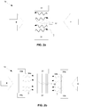
- FIG 2a schematically depicts an example arrangement of the target 14.
- the target 14 comprises a plurality of plates 32 of Mo-100 supported by a support structure 31.
- the plates 32 may be considered to be both an electron target and a photon target.
- the target 14 may receive photons ⁇ for a period of time, during which the proportion of Mo-99 in the target 14 increases and the proportion of Mo-100 in the target decreases.
- the target 14 is then removed from the radioisotope production apparatus 6 for processing and transportation to a radiopharmacy.
- Tc-99 which is the decay product of Mo-99, is then extracted and used in medical diagnostic applications.
- FIG 2b schematically depicts an alternative example arrangement of the target 14.
- a target 14 further comprises separate electron targets 34.
- the target plates 32 may be considered to be a photon target.
- the electron targets 34 may, for example, be formed from tungsten, tantalum or some other material which will decelerate the electrons and generate photons.
- the electron targets 34 may, however, be formed from the same material as a photon target (e.g. Mo-100).
- the electron targets are held by support structures 33a, 33b.
- targets 14 shown in Figures 2a and 2b comprise three plates, the targets may comprise any suitable number of plates.
- the described target comprises Mo-100
- the photon target may comprise any suitable material.
- the material of the target may be provided in any suitable shape and/or configuration. Shielding may be provided around targets 14 (e.g. lead shielding).
- Each electron target 34a, 34b of Figure 2b is depicted as a single block of material.
- each electron target may be provided as a plurality of plates.
- the plates may for example have a construction which corresponds to the construction of the target plates 32 described above.
- the support structures 33a, 33b may be configured to hold a plurality of electron target plates.
- the electron target 34 and the target plates 32 may be provided with conduits through which coolant fluid is flowed.
- target support structure may be provided.
- an electron beam splitter 12 is not present. In such embodiments a single electron beam may be incident upon the target 14.
- the electron injector 8 and the linear accelerator 10 form part of the enrichment apparatus 4 in addition to forming part of the radioisotope production apparatus 6.
- the enrichment apparatus 4 further comprises an undulator 16.
- the electron beam E enters the undulator following acceleration by the linear accelerator 10.
- the electron beam E may pass through a bunch compressor (not shown), disposed between the linear accelerator 10 and the undulator 16.
- the bunch compressor may be configured to spatially compress existing bunches of electrons in the electron beam E.
- the undulator 16 may comprise a plurality of modules or a single module.
- the or each module comprises a periodic magnet structure, which is operable to produce a periodic magnetic field and is arranged so as to guide the electron beam E produced by the electron injector 8 and linear accelerator 10 along a periodic path within that module.
- the periodic magnetic field produced by the undulator 16 causes the electrons to follow an oscillating path about a central axis.
- the electrons radiate electromagnetic radiation generally in the direction of the central axis of the undulator.
- the radiated electromagnetic radiation forms a beam B of radiation (e.g. infrared radiation).
- the beam B is directed such that it intersects with a gaseous flow of Mo, thereby facilitating Mo enrichment (as is described further below).
- the path followed by the electrons of the electron beam E in the undulator 16 may be sinusoidal and planar, with the electrons periodically traversing the central axis.
- the path may be helical, with the electrons rotating about the central axis.
- the type of oscillating path may affect the polarization of the radiation beam B emitted by the undulator 16.
- each bunch of electrons will have a spread of energies although this spread may be minimized as far as possible (by producing an electron beam E with low emittance).
- the resonant wavelength ⁇ em is equal to the first harmonic wavelength spontaneously radiated by electrons moving through the or each undulator module.
- the electron injector 8, accelerator 10 and undulator 16 may together be considered to be a free electron laser.
- the radiation beam B which is generated by the undulator 16 may be an infrared radiation beam.
- the radiation beam B may have a wavelength of around 10 microns (e.g. between 9 microns and 11 microns).
- a wavelength of around 10 microns is particularly suitable for enrichment of Molybdenum.
- the electron beam delivered to the undulator 16 from the accelerator 10 may have an energy of around 60 MeV.
- the undulator 16 may have a magnetic period of around 140 mm.
- An undulator length of around 4.5 meters may be sufficient to provide saturation of the radiation beam B emitted by the undulator.
- Each electron pulse of 75 pC bunch charge and 10 fs bunch length will create about 100 ⁇ J of infrared radiation.
- the bunch frequency is 375 MHz. With this set of electron beam and undulator parameters, a power in excess of 35 kW of the infrared radiation beam B may be generated.
- the bunch frequency may be around 1.3 GHz.
- the parameters of the electron beam E may be any suitable parameters, and may be selected to provide the radiation beam B with a desired power.
- a beam steering mirror 42 directs the infrared beam B towards a gaseous flow of Molybdenum (or a compound containing Molybdenum). Although a single beam steering mirror 42 is depicted, in practice two or more beam steering mirrors may be provided in order to allow the position of the radiation beam to be adjusted with additional flexibility. Due to the schematic nature of Figure 1 , it appears as though the infrared beam B intersects with the electron beam E. However, the infrared radiation beam B may easily be directed such that it travels around the electron beam E (e.g. over or under the electron beam).
- the enrichment apparatus 4 comprises a Molybdenum flow generator 44, magnets 45, a first receptacle 58 and a second receptacle 60
- the Molybdenum flow generator 44, magnets 45 and receptacles 58, 60 may be provided within a housing 62 which is sealed such that they are isolated from the external environment.
- a window 52 may be provided in the housing 62 to allow the infrared beam B to enter the housing.
- the Molybdenum flow generator 44 may comprise a container 54 which contains MoO 3 or MoF 6 , or some other gaseous Molybdenum containing molecule. Other gaseous Molybdenum containing molecules may be used, although these may need to be heated to a higher temperature, e.g. in excess of 200C, to form a gas (MoF 6 boils at just 34C).
- the container 54 includes an opening at one end. The opening comprises a nozzle 56 which is configured to generate a stream 46 of the gaseous Molybdenum containing molecules.
- the infrared beam B intersects the stream of gaseous Molybdenum containing molecules, and at least partially ionizes the stream.
- an oxygen atom may be stripped off the MoO 3 to form MoO 2 .
- a fluorine atom may be stripped off the MoF 6 to form MoF 5 .
- the stream of at least partially ionized molecules passes through a magnetic field 48 generated by the magnets 45. Additionally or alternatively a differential voltage applied to electrodes may be used to generate an electric field. An electric field and a magnetic field which are orthogonal to each other may provide the most effective separation of molecules.
- the path travelled by ions of the stream 46 through a magnetic field generated by the magnets 45 depends on the mass and charge of the ions. As a result molecules which have a higher-mass ions (e.g. molecules containing Mo-100) will exit the magnetic field at a different position and with a different trajectory than the lower mass ions (e.g. molecules containing Mo-92 to Mo-98).
- Higher-mass ions form a first ion stream 47a.
- This first ion stream 47a enters a first receptacle 58 and is retained within the first receptacle.
- ions having a mass which corresponds with a desired isotope are received by the first receptacle 58.
- the first receptacle 58 may for example contain a cooled plate onto which the gaseous molecules condense or solidify.
- the first receptacle may comprise a pump which pumps the gaseous molecules to a container.
- the second ion stream 47b has a different trajectory and enters a second receptacle 60.
- the second ion stream which consists of lower mass ions, is retained in the second receptacle 60.
- ions having a mass which does not corresponds with a desired isotope are received by the second receptacle 60.
- the second receptacle 60 may for example contain a cooled plate onto which the gaseous molecules condense or solidify.
- the second receptacle may comprise a pump which pumps the gaseous molecules to a container.
- the enrichment apparatus 4 separates molecules containing Mo-100 from molecules containing Mo-92 to Mo-98. In other words, enrichment of Molybdenum which increases the percentage of Mo-100 is achieved.
- the enriched Mo forms part of the target 32 which is described elsewhere in this document.
- the wavelength of the radiation beam B output from the undulator 16 may be selected via appropriate selection of the period of the undulator magnetic field, or the Lorentz factor of the electrons (which is determined by the energy of the electrons). As noted elsewhere in this document, there is a broad range of tens of MeV over which electrons may be incident upon Mo-100 and still provide reasonably efficient conversion to Mo-99. Thus, if a particular wavelength of infrared radiation beam B is required for enrichment of Mo, then the energy of the electron beam E may be adjusted until a radiation beam having that wavelength is generated by the undulator 16. Adjusting the energy of the electron beam E is significantly easier than adjusting the periodicity of the undulator.
- the energy of the electron beam E may be adjusted by adjusting power delivered to the accelerator 10.
- the adjustments may be controlled by a controller (not depicted).
- the controller may receive feedback which indicates the wavelength of the radiation beam, and may operate using a feedback loop to keep the wavelength of the radiation beam at a desired wavelength.
- FIG. 3 An alternative enrichment apparatus is schematically depicted in Figure 3 .
- a Molybdenum stream generator 44 comprising a container 54 and a nozzle 56 is used to provide a stream 70 of gaseous Molybdenum containing molecules (e.g. MoO 3 or MoF 6 ).
- the generator 44 is configured to generate a stream of molecules, and may be referred to as a molecular stream generator.
- a radiation beam B intersects the stream 70. The wavelength of the radiation beam is selected such that it excites a particular isotope of Molybdenum (e.g. Mo-100).
- the wavelength of the radiation beam B corresponds with an atomic transition of that isotope and not of other isotopes, and as a result is preferentially absorbed by that isotope.
- the isotope which preferentially absorbs the radiation beam B e.g. Mo-100
- the stream 70 comprises a first portion 70a which diverges at the same rate as upstream of the radiation beam B, and a second portion 70b which diverges at a greater rate than upstream of the radiation beam.
- a first receptacle 72 is arranged to receive the second portion 70b of the stream of molecules.
- the first receptacle 72 may comprise an annular opening.
- the first receptacle 72 may be generally annular.
- a central receptacle 74 is arranged to receive the first portion 70a of the stream molecules.
- the central receptacle 74 may by referred to as the second receptacle. In this way an isotope such as Mo-100 may be separated from other isotopes such as MO-92 to MO-98.
- the first receptacle 72 may for example contain a cooled plate onto which the molecules containing the desired isotope condense or solidify.
- the first receptacle 72 may comprise a pump which pumps the molecules containing the desired isotope to a container.
- the second receptacle 74 may for example contain a cooled plate onto which the other molecules condense or solidify.
- the second receptacle 74 may comprise a pump which pumps the other molecules to a container.
- the enrichment apparatus depicted in Figure 3 uses a radiation beam B with a well-controlled wavelength. That is, the wavelength is controlled sufficiently accurately to ensure that it predominantly excites one Molybdenum isotope in preference to other Molybdenum isotopes.
- the electron injector 8, accelerator 10 and undulator 16 (which together may comprise a free electron laser) provide good stability and adjustability, and are thus capable of providing a radiation beam B with a desired wavelength which is sufficiently well controlled.
- the wavelength of the radiation beam B may be controlled by adjusting the power delivered to the accelerator 10.
- the electron orbits of Mo-100 are most different to the electron orbits of Mo-92 to Mo-98 close to the nucleus.
- the energies of these electron orbits correspond with wavelengths which are shorter than infrared radiation.
- the radiation beam B may have a shorter wavelength than infrared radiation, e.g. ultraviolet radiation.
- An ultraviolet radiation beam may for example be generated by applying non-linear effects such as frequency doubling to the infrared beam (e.g. using one or more frequency doubling crystals).
- an electron beam splitter 12 is used to split the electron beam E.
- the electron beam splitter 12 also separates the electron beam E from the infrared radiation beam B.
- magnets may be used to bend the path of the electron beam E such that the electron beam bends away from the infrared radiation beam B. In this way the electron beam E and the infrared radiation beam B may be separated.
- embodiments of the invention may also be used for enrichment of other materials such as for example uranium.
- the electron injector 8, accelerator 10 and undulator 16 may be configured to provide an electron beam E with a current of 10 mA or more.
- the current may, for example, be up to 100 mA or more.
- An electron beam E with a high current e.g. 10 mA or more is advantageous because it increases the specific activity of the radioisotope produced by the radioisotope production apparatus 6.
- Mo-100 may be converted to Mo-99 (a desired radioisotope) using very hard X-ray photons generated by an electron beam hitting an electron target.
- the half-life of Mo-99 is 66 hours.
- the threshold of specific activity of Mo-99 used in medical applications in Europe should be 100 Ci/g, and thus Mo-99 with a specific activity of 40 Ci/g or less is not useful.
- an electron beam current of 10 mA will generate Mo-99 at 10 times the rate of generation provided by an electron beam current of 1mA.
- the electron beam current used by embodiments of the invention may be sufficiently high that a specific activity of Mo-99 in excess of 100 Ci/g is achieved.
- an embodiment of the invention may provide an electron beam with a beam current of around 30 mA.
- the Mo-100 target may for example comprise of 20 plates with a diameter of around 25mm and a thickness of around 0.5mm. Other numbers of plates, which may have non-circular shapes and may have other thicknesses, may be used.
- an electron injector of an embodiment of the invention may be a photo-cathode which is illuminated by a pulsed laser beam.
- the laser may, for example, comprise a Nd:YAG laser together with associated optical amplifiers.
- the laser may be configured to generate picosecond laser pulses.
- the current of the electron beam may be adjusted by adjusting the power of the pulsed laser beam. For example, increasing the power of the pulsed laser beam will increase the number of electrons emitted from the photo-cathode and thereby increase the electron beam current.
- the electron beam E used by a radioisotope production apparatus 6 may, for example, have a diameter of 1mm and a divergence of 1mrad. Increasing the current in the electron beam E will tend to cause the electrons to spread out due to space charge effects, and thus may increase the diameter of the electron beam. Increasing the current of the electron beam may therefore reduce the brightness of the electron beam.
- the radioisotope production apparatus 6 does not require an electron beam E with, for example, a diameter of 1mm and may utilize an electron beam with a greater diameter.
- increasing the current of the electron beam may not reduce the brightness of the beam to such an extent that radioisotope production is significantly negatively affected.
- providing the electron beam with a diameter greater than 1mm may be advantageous because it spreads the thermal load delivered by the electron beam. It will be appreciated, however, that other injector types may also be used.
- embodiments of the invention may be used to generate other radioisotopes.
- embodiments of the invention may be used to generate any radioisotope which may be formed via direction of very hard X-rays onto a source material.
- An advantage of the invention is that it provides production of radioisotopes without requiring the use of a high flux nuclear reactor.
- a further advantage is that it does not require the use of highly enriched uranium (a dangerous material which is subject to non-proliferation rules).
- embodiments of the invention have been described as using Mo-100 to generate Mo-99 radioisotope which decays to Tc-99, other medically useful radioisotopes may be generated using embodiments of the invention.
- embodiments of the invention may be used to generate Ge-68, which decays to Ga-68.
- Embodiments of the invention may be used to generate W-188, which decays to Re-188.
- Embodiments of the invention may be used to generate Ac-225, which decays to Bi-213, Sc-47, Cu-64, Pd-103, Rh-103m, In-Ill, 1-123, Sm-153, Er-169 and Re-186.
- Embodiments of the invention have been described in the context of a free electron laser FEL which outputs an infrared radiation beam.
- a free electron laser FEL may be configured to output radiation having any wavelength.
- Some embodiments of the invention may therefore comprise a free electron laser which outputs a radiation beam which is not an infrared radiation beam.
Landscapes
- Chemical & Material Sciences (AREA)
- Chemical Kinetics & Catalysis (AREA)
- General Chemical & Material Sciences (AREA)
- Physics & Mathematics (AREA)
- Engineering & Computer Science (AREA)
- General Engineering & Computer Science (AREA)
- High Energy & Nuclear Physics (AREA)
- Particle Accelerators (AREA)
- Saccharide Compounds (AREA)
Priority Applications (10)
| Application Number | Priority Date | Filing Date | Title |
|---|---|---|---|
| EP18200179.2A EP3637436A1 (fr) | 2018-10-12 | 2018-10-12 | Enrichissement et production de radio-isotopes |
| US17/283,823 US11908591B2 (en) | 2018-10-12 | 2019-09-13 | Enrichment and radioisotope production |
| EP19765740.6A EP3864676B1 (fr) | 2018-10-12 | 2019-09-13 | Enrichissement et production de radio-isotopes |
| CA3115586A CA3115586A1 (fr) | 2018-10-12 | 2019-09-13 | Enrichissement et production de radio-isotopes |
| PCT/EP2019/074443 WO2020074209A1 (fr) | 2018-10-12 | 2019-09-13 | Enrichissement et production de radio-isotopes |
| CN201980066955.8A CN112823398B (zh) | 2018-10-12 | 2019-09-13 | 富集和放射性同位素生产 |
| JP2021514115A JP7325501B2 (ja) | 2018-10-12 | 2019-09-13 | 濃縮及び放射性同位元素生成 |
| NL2023827A NL2023827A (en) | 2018-10-12 | 2019-09-13 | Enrichment and Radioisotope Production |
| KR1020217010229A KR102810725B1 (ko) | 2018-10-12 | 2019-09-13 | 농축 및 방사성 동위원소 생산 기술 |
| TW108135793A TWI811463B (zh) | 2018-10-12 | 2019-10-03 | 富集和放射性同位素生產 |
Applications Claiming Priority (1)
| Application Number | Priority Date | Filing Date | Title |
|---|---|---|---|
| EP18200179.2A EP3637436A1 (fr) | 2018-10-12 | 2018-10-12 | Enrichissement et production de radio-isotopes |
Publications (1)
| Publication Number | Publication Date |
|---|---|
| EP3637436A1 true EP3637436A1 (fr) | 2020-04-15 |
Family
ID=63840742
Family Applications (2)
| Application Number | Title | Priority Date | Filing Date |
|---|---|---|---|
| EP18200179.2A Withdrawn EP3637436A1 (fr) | 2018-10-12 | 2018-10-12 | Enrichissement et production de radio-isotopes |
| EP19765740.6A Active EP3864676B1 (fr) | 2018-10-12 | 2019-09-13 | Enrichissement et production de radio-isotopes |
Family Applications After (1)
| Application Number | Title | Priority Date | Filing Date |
|---|---|---|---|
| EP19765740.6A Active EP3864676B1 (fr) | 2018-10-12 | 2019-09-13 | Enrichissement et production de radio-isotopes |
Country Status (9)
| Country | Link |
|---|---|
| US (1) | US11908591B2 (fr) |
| EP (2) | EP3637436A1 (fr) |
| JP (1) | JP7325501B2 (fr) |
| KR (1) | KR102810725B1 (fr) |
| CN (1) | CN112823398B (fr) |
| CA (1) | CA3115586A1 (fr) |
| NL (1) | NL2023827A (fr) |
| TW (1) | TWI811463B (fr) |
| WO (1) | WO2020074209A1 (fr) |
Cited By (2)
| Publication number | Priority date | Publication date | Assignee | Title |
|---|---|---|---|---|
| WO2023107039A3 (fr) * | 2021-12-10 | 2023-07-27 | T.C. Ankara Universitesi Rektorlugu | Procédé de production de source de radio-isotope pr-142 pour curiethérapie à débit de dose moyen/débit de dose élevé sous la forme d'une source linéaire et en disque |
| US12573517B2 (en) | 2021-08-02 | 2026-03-10 | Battelle Energy Alliance, Llc | Methods for producing radionuclides |
Families Citing this family (4)
| Publication number | Priority date | Publication date | Assignee | Title |
|---|---|---|---|---|
| CA3003766C (fr) * | 2015-11-06 | 2024-02-20 | Asml Netherlands B.V. | Systeme de production de radioisotope au moyen d'un diviseur de faisceau d'electrons |
| CN113238270B (zh) * | 2021-06-25 | 2024-11-08 | 清华大学 | 铀矿石的检测方法、装置、系统、设备及介质 |
| JP7822887B2 (ja) * | 2022-07-26 | 2026-03-03 | 株式会社東芝 | 放射性同位体製造装置および放射性同位体製造方法 |
| CN116234142A (zh) * | 2023-02-27 | 2023-06-06 | 中国科学院近代物理研究所 | 一种产生医用同位素药物的电子直线加速器及其使用方法 |
Citations (3)
| Publication number | Priority date | Publication date | Assignee | Title |
|---|---|---|---|---|
| GB1355950A (en) * | 1970-03-25 | 1974-06-12 | Jersey Nuclear Avco Isotopes | Isotopic separation process |
| WO2016139008A1 (fr) * | 2015-03-03 | 2016-09-09 | Asml Netherlands B.V. | Production de radio-isotopes |
| US9892808B2 (en) * | 2013-05-23 | 2018-02-13 | Canadian Light Source Inc. | Production of molybdenum-99 using electron beams |
Family Cites Families (21)
| Publication number | Priority date | Publication date | Assignee | Title |
|---|---|---|---|---|
| US3204101A (en) * | 1962-09-04 | 1965-08-31 | Lockheed Aircraft Corp | Infrared spectrometer for target detection and tracking |
| JPS53100398A (en) | 1977-02-15 | 1978-09-01 | Kyoto Daigaku Souchiyou | Method of separating uranium isotope by infrared rays |
| JPS605330B2 (ja) | 1981-12-26 | 1985-02-09 | 富士通株式会社 | 同位体分離装置 |
| JP2851144B2 (ja) | 1990-07-31 | 1999-01-27 | 株式会社東芝 | 同位体分離システム |
| JPH0647257A (ja) * | 1992-07-29 | 1994-02-22 | Toshiba Corp | 同位体分離装置 |
| EP1059708B1 (fr) * | 1998-11-10 | 2006-01-25 | Kabushiki Kaisha IDX Technologies | Appareil pour photoreaction |
| US6743481B2 (en) * | 2000-06-01 | 2004-06-01 | Seagate Technology Llc | Process for production of ultrathin protective overcoats |
| US6614505B2 (en) * | 2001-01-10 | 2003-09-02 | Asml Netherlands B.V. | Lithographic projection apparatus, device manufacturing method, and device manufactured thereby |
| JP2003017788A (ja) * | 2001-07-03 | 2003-01-17 | Japan Atom Energy Res Inst | 自由電子レーザー装置において、電子ビームからレーザー光への高い引出効率とフェムト秒領域極短パルスを実現する方法及び装置 |
| US20140008210A1 (en) | 2012-07-06 | 2014-01-09 | Aviva Biosciences Corporation | Methods and compositions for separating or enriching cells |
| JP4599342B2 (ja) * | 2005-12-27 | 2010-12-15 | エーエスエムエル ネザーランズ ビー.ブイ. | 光学装置、リソグラフィ装置、および、デバイス製造方法 |
| WO2009135163A2 (fr) * | 2008-05-02 | 2009-11-05 | Phoenix Nuclear Labs Llc | Dispositif et procédé pour produire des isotopes médicaux |
| US20100215137A1 (en) | 2009-02-24 | 2010-08-26 | Yasuki Nagai | Method and apparatus for producing radioisotope |
| US9047997B2 (en) * | 2009-11-12 | 2015-06-02 | Global Medical Isotope Systems Llc | Techniques for on-demand production of medical isotopes such as Mo-99/Tc-99m and radioactive iodine isotopes including I-131 |
| EP2584347B1 (fr) * | 2011-10-19 | 2014-04-02 | Deutsches Elektronen-Synchrotron DESY | Installation et procédé de détermination de structure moléculaire |
| CN108873623B (zh) * | 2013-06-18 | 2021-04-06 | Asml荷兰有限公司 | 光刻方法和光刻系统 |
| JP6571092B2 (ja) * | 2013-09-25 | 2019-09-04 | エーエスエムエル ネザーランズ ビー.ブイ. | ビームデリバリ装置及び方法 |
| NL2013663A (en) * | 2013-11-06 | 2015-05-07 | Asml Netherlands Bv | Free electron laser. |
| WO2016023740A2 (fr) * | 2014-08-15 | 2016-02-18 | Asml Netherlands B.V. | Source de rayonnement |
| CA3003766C (fr) * | 2015-11-06 | 2024-02-20 | Asml Netherlands B.V. | Systeme de production de radioisotope au moyen d'un diviseur de faisceau d'electrons |
| CN105609145B (zh) * | 2015-12-25 | 2017-09-26 | 中国科学院合肥物质科学研究院 | 一种加速器驱动的质子硼聚变核能装置 |
-
2018
- 2018-10-12 EP EP18200179.2A patent/EP3637436A1/fr not_active Withdrawn
-
2019
- 2019-09-13 NL NL2023827A patent/NL2023827A/en unknown
- 2019-09-13 KR KR1020217010229A patent/KR102810725B1/ko active Active
- 2019-09-13 US US17/283,823 patent/US11908591B2/en active Active
- 2019-09-13 JP JP2021514115A patent/JP7325501B2/ja active Active
- 2019-09-13 EP EP19765740.6A patent/EP3864676B1/fr active Active
- 2019-09-13 WO PCT/EP2019/074443 patent/WO2020074209A1/fr not_active Ceased
- 2019-09-13 CN CN201980066955.8A patent/CN112823398B/zh active Active
- 2019-09-13 CA CA3115586A patent/CA3115586A1/fr active Pending
- 2019-10-03 TW TW108135793A patent/TWI811463B/zh active
Patent Citations (3)
| Publication number | Priority date | Publication date | Assignee | Title |
|---|---|---|---|---|
| GB1355950A (en) * | 1970-03-25 | 1974-06-12 | Jersey Nuclear Avco Isotopes | Isotopic separation process |
| US9892808B2 (en) * | 2013-05-23 | 2018-02-13 | Canadian Light Source Inc. | Production of molybdenum-99 using electron beams |
| WO2016139008A1 (fr) * | 2015-03-03 | 2016-09-09 | Asml Netherlands B.V. | Production de radio-isotopes |
Cited By (2)
| Publication number | Priority date | Publication date | Assignee | Title |
|---|---|---|---|---|
| US12573517B2 (en) | 2021-08-02 | 2026-03-10 | Battelle Energy Alliance, Llc | Methods for producing radionuclides |
| WO2023107039A3 (fr) * | 2021-12-10 | 2023-07-27 | T.C. Ankara Universitesi Rektorlugu | Procédé de production de source de radio-isotope pr-142 pour curiethérapie à débit de dose moyen/débit de dose élevé sous la forme d'une source linéaire et en disque |
Also Published As
| Publication number | Publication date |
|---|---|
| JP7325501B2 (ja) | 2023-08-14 |
| NL2023827A (en) | 2020-05-07 |
| CN112823398A (zh) | 2021-05-18 |
| CN112823398B (zh) | 2024-05-28 |
| KR20210072769A (ko) | 2021-06-17 |
| EP3864676A1 (fr) | 2021-08-18 |
| KR102810725B1 (ko) | 2025-05-20 |
| CA3115586A1 (fr) | 2020-04-16 |
| EP3864676B1 (fr) | 2022-11-02 |
| TW202029220A (zh) | 2020-08-01 |
| US20210343443A1 (en) | 2021-11-04 |
| JP2022503704A (ja) | 2022-01-12 |
| TWI811463B (zh) | 2023-08-11 |
| WO2020074209A1 (fr) | 2020-04-16 |
| US11908591B2 (en) | 2024-02-20 |
Similar Documents
| Publication | Publication Date | Title |
|---|---|---|
| EP3864676B1 (fr) | Enrichissement et production de radio-isotopes | |
| US20210375498A1 (en) | Radioisotope production | |
| Chen et al. | Perspectives on relativistic electron–positron pair plasma experiments of astrophysical relevance using high-power lasers | |
| US5848110A (en) | Method and apparatus for transmutation of atomic nuclei | |
| Dudnikov | Development and applications of negative ion sources | |
| Chehab | Positron sources | |
| CN112309590A (zh) | 一种低温可控核聚变装置及其实现方式 | |
| WO2016139008A1 (fr) | Production de radio-isotopes | |
| Titov et al. | Dimuon production by laser-wakefield accelerated electrons | |
| Adelmann et al. | Cost-effective design options for IsoDAR | |
| Garten et al. | Laser-plasma ion beam booster based on hollow-channel magnetic vortex acceleration | |
| Hadjisolomou et al. | High-energy photon generation from self-organized plasma cavities in field-enhanced laser-preplasma interactions | |
| Ledingham et al. | Laser-induced nuclear physics and applications | |
| Burkhardt | Accelerators for particle physics | |
| WO2025114702A1 (fr) | Appareil et procédé de photolyse d'un matériau cible | |
| Demchenko et al. | A channel of high current deuteron linac with low radiation losses | |
| Balakin et al. | The VLEPP project status report | |
| Pelaghia et al. | Nuclear fusion of protons with boron | |
| Riisager | The HIE‐ISOLDE project | |
| Borge | Results of the ISOLDE Facility and the HIE-ISOLDE Project | |
| Yennello | Present Capabilities and Future Plans of the Texas A&m Cyclotron Institute | |
| Frois et al. | ELFEαDESY: an electron laboratory for Europe at DESY | |
| Liatard | The PIAFE project at Grenoble |
Legal Events
| Date | Code | Title | Description |
|---|---|---|---|
| PUAI | Public reference made under article 153(3) epc to a published international application that has entered the european phase |
Free format text: ORIGINAL CODE: 0009012 |
|
| STAA | Information on the status of an ep patent application or granted ep patent |
Free format text: STATUS: THE APPLICATION HAS BEEN PUBLISHED |
|
| AK | Designated contracting states |
Kind code of ref document: A1 Designated state(s): AL AT BE BG CH CY CZ DE DK EE ES FI FR GB GR HR HU IE IS IT LI LT LU LV MC MK MT NL NO PL PT RO RS SE SI SK SM TR |
|
| AX | Request for extension of the european patent |
Extension state: BA ME |
|
| STAA | Information on the status of an ep patent application or granted ep patent |
Free format text: STATUS: THE APPLICATION IS DEEMED TO BE WITHDRAWN |
|
| 18D | Application deemed to be withdrawn |
Effective date: 20201016 |