EP1059708B1 - Appareil pour photoreaction - Google Patents
Appareil pour photoreaction Download PDFInfo
- Publication number
- EP1059708B1 EP1059708B1 EP99971974A EP99971974A EP1059708B1 EP 1059708 B1 EP1059708 B1 EP 1059708B1 EP 99971974 A EP99971974 A EP 99971974A EP 99971974 A EP99971974 A EP 99971974A EP 1059708 B1 EP1059708 B1 EP 1059708B1
- Authority
- EP
- European Patent Office
- Prior art keywords
- interactive region
- laser beam
- mirror
- optical
- interaction
- Prior art date
- Legal status (The legal status is an assumption and is not a legal conclusion. Google has not performed a legal analysis and makes no representation as to the accuracy of the status listed.)
- Expired - Lifetime
Links
Images




Classifications
-
- H—ELECTRICITY
- H05—ELECTRIC TECHNIQUES NOT OTHERWISE PROVIDED FOR
- H05G—X-RAY TECHNIQUE
- H05G2/00—Apparatus or processes specially adapted for producing X-rays, not involving X-ray tubes, e.g. involving generation of a plasma
-
- H—ELECTRICITY
- H01—ELECTRIC ELEMENTS
- H01S—DEVICES USING THE PROCESS OF LIGHT AMPLIFICATION BY STIMULATED EMISSION OF RADIATION [LASER] TO AMPLIFY OR GENERATE LIGHT; DEVICES USING STIMULATED EMISSION OF ELECTROMAGNETIC RADIATION IN WAVE RANGES OTHER THAN OPTICAL
- H01S3/00—Lasers, i.e. devices using stimulated emission of electromagnetic radiation in the infrared, visible or ultraviolet wave range
- H01S3/05—Construction or shape of optical resonators; Accommodation of active medium therein; Shape of active medium
- H01S3/08—Construction or shape of optical resonators or components thereof
- H01S3/081—Construction or shape of optical resonators or components thereof comprising three or more reflectors
-
- G—PHYSICS
- G21—NUCLEAR PHYSICS; NUCLEAR ENGINEERING
- G21K—HANDLING OF PARTICLES OR IONISING RADIATION NOT OTHERWISE PROVIDED FOR; IRRADIATION DEVICES; GAMMA RAY OR X-RAY MICROSCOPES
- G21K1/00—Arrangements for handling particles or ionising radiation, e.g. focusing or moderating
-
- G—PHYSICS
- G21—NUCLEAR PHYSICS; NUCLEAR ENGINEERING
- G21K—HANDLING OF PARTICLES OR IONISING RADIATION NOT OTHERWISE PROVIDED FOR; IRRADIATION DEVICES; GAMMA RAY OR X-RAY MICROSCOPES
- G21K1/00—Arrangements for handling particles or ionising radiation, e.g. focusing or moderating
- G21K1/06—Arrangements for handling particles or ionising radiation, e.g. focusing or moderating using diffraction, refraction or reflection, e.g. monochromators
-
- G—PHYSICS
- G21—NUCLEAR PHYSICS; NUCLEAR ENGINEERING
- G21K—HANDLING OF PARTICLES OR IONISING RADIATION NOT OTHERWISE PROVIDED FOR; IRRADIATION DEVICES; GAMMA RAY OR X-RAY MICROSCOPES
- G21K1/00—Arrangements for handling particles or ionising radiation, e.g. focusing or moderating
- G21K1/10—Scattering devices; Absorbing devices; Ionising radiation filters
- G21K1/12—Resonant absorbers or driving arrangements therefor, e.g. for Moessbauer-effect devices
Definitions
- the present invention relates to a device on which a laser beam is reflected multiple times by a plurality of confronting concave mirrors as defined in claim 1, the reflected optical path is centralized to form an interactive region of high photon density, and an interaction target such as gas, liquid, a solid body, plasma, a particle beam or an electron beam is introduced into the interactive region to cause an optical interaction such as optical excitation, optical ionization, photolysis, optical dissociation, photosynthesis, optical generation and optical analysis.
- an interaction target such as gas, liquid, a solid body, plasma, a particle beam or an electron beam
- Gas, liquid, solid bodies and particle beams perform strong optical interactions with laser beams of specified wavelengths corresponding to the atoms and molecules composing them.
- a pair of confronting curvilinear mirrors are generally used for forming an optical resonator in which optical interactions are carried out.
- a region of high photon density is centralized to the center of the resonator interior.
- Such a region is extremely too small and too short to reserve long interaction time of atoms and molecules passing through the region.
- an aperture formed through each curvilinear mirror is designed as small as possible to reduce optical loss.
- introduction of beams, atoms and molecules into the interactive region is rendered to be highly difficult to practice sufficiently.
- laser beams of extremely short pulses Use of such laser beams makes the interactive region extremely small in terms of time and space dimension and, consequently, it is almost infeasible to cause optical interactions effectively.
- an optical interaction device comprising first and second mirror sets (A, B) disposed in a confronting arrangement to each other so as to form an interactive region with centralized laser beams, each including a plurality of concave mirrors (A n , B n ) disposed in annular arrangements around a common axis, means for generating a laser beam for repeated reflections between said mirror sets (A, B), laser beam guide means for introducing said laser beam into said interactive region and for outputting therefrom after prescribed reciprocal reflections between said first and second mirror sets (A,B) means for introducing an interaction target into said interactive region, wherein each concave mirror in said first mirror set (A) is disposed in an arrangement such that an incident laser beam is reflected towards a corresponding concave mirror in said second mirror set after passage through a prescribed position on said common axis, thereby forming said interactive region of a high photon density with centralization of reflected beams at said prescribed position on said common axis, and
- the present invention seeks to provide an optical interaction device which removes the above-described problems inherent to the conventional arts and assures high efficiency in use of laser beams.
- the present invention also seeks to provide an optical interaction device which is able to reserve large apertures for incidence and exit of interaction media and interaction targets, a large interactive region with high photon density and along interaction time.
- an optical interaction device includes a pair of confronting first and second mirror sets each of which is made up of a plurality concave mirrors disposed in a annular arrangement around a common axis of the interactive region.
- a laser beam generated by laser beam generating means is led to one concave mirror selected from the first mirror set via a laser beam guide means.
- Each concave mirror in the first mirror set reflects an incident beam to pass it through a prescribed position on an axis of the interactive region to direct a reflected beam to a corresponding concave mirror in the second mirror set.
- an interactive region of high photon density is formed at a position where reflected beams are centralized.
- Each concave mirror in the second mirror set reflects incident beam from a corresponding concave mirror in the first mirror set to direct it to an adjacent concave mirror.
- each laser beam reciprocates between the first and second mirror sets whilst sequentially moving in the circumferential direction of the first and second mirror sets. Interaction between the laser beams and the interaction target takes places in an interaction region where the laser beams pass collectively.
- incident laser beams to the concave mirrors of the first, mirror set are reflected in a collected fashion and centralized at a focus on an axis of the interactive region. Then, each reflected beam can be directed to a corresponding concave mirror of the second mirror set. Thus, a interaction region of high photon density can be formed at a position where the reflected beams are centralized.
- Figure 1 shows a diagrammatic view of the optical interaction device in accordance with the present invention.
- ( a ) is a side plan view and ( b ) as well as ( c ) are front plan view of the respective mirror sets.
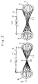
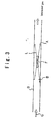
- the optical paths of laser beams reciprocating between the mirror sets A and B are shown in Figure 2.
- the optical interaction device 11 includes a pair of mirror sets A and B disposed in a confronting arrangement.
- the mirror set A includes multiple concave mirrors A1, A2 to An which are disposed annularly around an axis of the interactive region O of beams.
- the mirror set B includes multiple concave mirrors B1, B2 to Bn which are disposed annularly around an axis of the interactive region O of beams.
- An aperture Ap is formed on the inner side of each annular arrangement of the concave mirrors for introduction of electron beams.
- the mirrors of the mirror sets A and B appear to be disposed on curved planes in the illustration in order to show that the concave mirrors have a same focal length, the concave mirrors are disposed on flat planes in practice.
- Each concave mirror An of the mirror set A reflects an incident laser beam to focus the same at a prescribed position on the axis of the interactive region O and the reflected laser beam is directed to a corresponding concave mirror Bn of the mirror set B.
- the optical path L1 of the laser beam traveling from the concave mirror An to the concave mirror Bn whilst passing the focus is hereinafter referred to as " a forward trajectory ".
- Each concave mirror Bn of the mirror set B reflects an incident laser beam from a corresponding concave mirror An of the mirror set A to direct the same to an adjacent concave mirror An+1, the adjacent concave mirror being biased from the concave mirror in the direction of ⁇ .
- the optical path L2 of the laser beam traveling from the concave mirror Bn to the concave mirror Bn+1 is hereinafter referred to as " a return trajectory ".
- the laser beams introduced to the mirror sets A and B sequentially shift their reflected beams in the circumferential direction ⁇ of the annular arrangement of the concave mirrors. Stated otherwise, the beams travel from A1 to B1, from B1 to A2, from A2 to B2 - - - from An to Bn and from Bn to An+1, respectively.
- Figure 1 only the optical paths of reciprocating laser beams from A1 to A6 are shown for simplification purposes.
- the inter-mirror distance of the forward trajectory L1 from a concave mirror An to a corresponding concave mirror is set to 2Z and the radius of curvature of the concave mirror are set to 2Z.
- the laser beam L2 reflected by the concave mirror B1 travels to the concave mirror A2 in a parallel mode.
- the laser beam reflected by the concave mirror A2 focuses at the point Oa. This process is sequentially repeated. In this process, the laser beams L1 in the forward trajectory all focus at the point Oa and the laser beams L2 in the return trajectory all travel in a parallel mode.
- the reflected laser beam travels in a parallel mode. So, all laser beams L1 reflected by the concave mirrors A travel, after passing the point Oa on the axis of the interactive region, in a parallel mode towards the concave mirrors B. Upon reflection by the concave mirrors B, the laser beams travel in a converged mode towards the concave mirrors A. Sequential reflections are repeated all in this mode.
- the laser beams in a parallel mode are all centralized at the point Oa to form an interaction region of a high photon density around the point Oa.
- the reflected laser beams L2 in the return trajectory are also collected within an narrow region around the point Oa. So, the laser beams L2 in the return trajectory may also be utilized for the optical interaction.
- an interaction target such as gas, liquid, a solid body, plasma, particle beams and electron beams are introduce along the axis into the region between the mirror sets A and B, laser beams and the interaction target perform a desired interaction within the interactive region near the point Oa where the laser beams focus.
- Laser beam pulses shored at the above-described optical interaction device are classified into the following three types:
- the laser beams are introduced into the system in either of the three modes, the laser beams are collected at the center of the region between the mirror sets, where optical paths cross, to enhance photon density.
- gas G is passed for optical interaction of gaseous atoms or molecules, as an interaction target, through the interactive region F in the optical interaction device in accordance with the present invention to cause optical interactions such as optical excitation with laser beams L.
- laser beams of a proper wavelength are selected and an interactive region F is formed in a duct and gas G such as dioxin gas or NoX gas is introduced into the interactive region F to cause efficient optical dissociation of the interaction target.
- gas G such as dioxin gas or NoX gas
- oxygen gas G is introduced, ozone can be synthesized optically. Namely, through optical interaction of gaseous atoms or molecules with laser beams within the interactive region, optical photolysis, optical synthesis, optical analysis and other optical treatments can be performed.
- a liquid or solid conversion element CE is placed as an interaction target in an interactive region F for generation of laser beams with wavelength conversion.
- Optical excitation is caused by use of proper laser beams and laser beams of a specified wavelength are oscillated by an optical resonator RE arranged on the axis O of the interactive region.
- the liquid or solid conversion element CE is introduced through an inlet IN and placed in the interactive region F for excitation by laser beams L, thereby generating laser beams with wavelength conversion.
- An wavelength converted laser beam L3 is stored at an optical resonator RE for intended use.
- laser beams L generated by a laser beam generator LA are introduced into a space between mirror sets A and B to form an interactive region F for charge conversion of particle beams.
- a high energy hydrogen beam H 0 is introduced as an interaction target into the interactive region F, the beam is excited efficiently through optical interaction with the laser beams L.
- An excited hydrogen beam is ionized within a magnetic field generated by charge converting magnets U which are arranged embracing the interactive region F for charge conversion.
- Ionized hydrogen ion H + is subjected for reciprocation between the mirror sets A and B via a ring accelerator RA.
- the interactive region F is utilized for charge conversion of the ring accelerator RA.
- an ion beam IB from an ion source is introduced into an interactive region F for use as a multivalent ion source. Lots of electrons are stripped off the ion beam through optical ionization to form multivalent ion with high charge. More specifically, laser beams L generated at a laser generator LA are introduced into a space between mirror sets A and B to form an interactive region F. An ion beam IB from the ion source is introduced into the interactive region F in which the ion beam is excited to increase charge and generate a multivalent ion beam.
- the multivalent ion beam is accelerated at an accelerator.
- a monovalent oxygen ion beam from the ion source is introduced into the interactive region F to generate a octavalent ion beam which is accelerated at the accelerator to an energy of eight times higher.
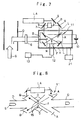
- a vacuum change V is provided in connection with a duct D for flow of exhaust gas G as shown in Figure 7.
- the vacuum chamber V is associated with a vacuum pump 21 for evacuation thereof.
- the duct D is provided with a compressor 6 for provisional compression of the exhaust gas G.
- the exhaust gas G is passed to a nozzle N via a shutter valve of the compressor 6 for ejection into the vacuum chamber V. This ejection causes inflation and cooling of the exhaust gas G.
- the nozzle N is disposed with its mouth being directed to the interactive region F.
- the optical interaction device 11 performs resonance ionization of micro-components such as dioxin within the exhaust gas G.
- Laser beams L are supplied into the optical interaction device 11 from a given source outside the vacuum chamber V.
- a laser beam generator LA, an optical switch 7, a polariscope 8 and reflection mirrors 9 are disposed outside the vacuum chamber V for selection of laser beams of a specified wavelength in accordance with the kind of the micro-component such as dioxin and for supply into the optical interaction device 11.
- Laser beams of a specified wavelength is capable of ionizing a specified substance through resonance.
- a long pulse system is applied to ionization of dioxin.
- high output laser beams of about two nano-meter wavelength are used, only electrons can be stripped off the dioxin for ionization without causing any decomposition of dioxin molecules.
- the vacuum chamber V is provided with a collection guide 10 for electric absorption of ions.
- the collection guide 10 captures ionized dioxin by its electric charge.
- the dioxin so captured by the collection guide 10 is passed to an analyzer 12 of travel time and mass.
- the resultant mass spectrum is visually indicated on a monitor 13. Quantitative and qualitative analysis of dioxin can be carried out on the basis of the resultant mass spectrum.
- the optical interaction device in accordance with the present invention when used for removal of harmful micro-components, is disposed in a duct for exhaust gas G and a throttle 15 is disposed therein in order to ionize dioxin by a short pulse process.
- a throttle 15 is disposed therein in order to ionize dioxin by a short pulse process.
- no compression of the exhaust gas is employed since only decomposition and harmlessness of the dioxin are intended without any need for high degree sensitivity. Therefore, interaction is carried out under atmospheric conditions.
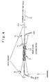
- the optical interaction device in accordance with the present invention is used for generation of an X-ray beam.
- 11 indicates the optical interaction device
- LA indicates a laser beam generator
- 23 indicates a SHG (secondary harmonics generator)
- 24 indicates a dichroic mirror
- a and B indicate mirror sets which are disposed within a vacuum chamber V.
- a laser beam L of a selected wavelength is introduced into the optical interaction device 11 and an interactive region F of a high photon density is formed by centralization of the laser beam L.
- An electron beam e is introduced into the interactive region f in the vacuum chamber V along the axis O of the interactive region for interaction with the laser beam 1.
- the laser beam made up of optical particles crashes against the electron beam to generate an X-ray beam through dispersion of photon beam.
- a laser beam i.e. a sufficiently powerful electro-magnetic wave
- Ef indicates scattered electron.
- the interaction device 11 is arranged for two step excitation it includes two pairs of mirror sets A, B.A' and B' which arranged side by side so as to have a common interactive region F.
- Laser beams L and L' of different wavelength are introduced into the system.
- IR laser beam and YAG-2nd laser beam are used.
- a particle beam PB is introduced as an interactive target
- the first step optical interaction is performed by the YAG-2nd laser beam and the second step optical interaction is performed by the IR laser beam.
- the present invention can be employed in industrial fields in which optical interactions such as optical excitation, optical ionization, optical photolysis, optical dissociation, photosynthesis, optical generation and optical analysis are performed through interaction of laser beams of a specified wavelength with gaseous atoms and molecules, liquids and solid bodies.
Landscapes
- Physics & Mathematics (AREA)
- Engineering & Computer Science (AREA)
- Spectroscopy & Molecular Physics (AREA)
- General Engineering & Computer Science (AREA)
- High Energy & Nuclear Physics (AREA)
- Plasma & Fusion (AREA)
- Optics & Photonics (AREA)
- Electromagnetism (AREA)
- Physical Or Chemical Processes And Apparatus (AREA)
- Lasers (AREA)
Claims (13)
- Dispositif d'interaction optique (11) comprenant un premier et un second jeux de miroirs (A, B) disposés suivant un arrangement en face les uns des autres de manière à former une région interactive (10) avec des faisceaux laser se croisant, chaque jeu comprenant une pluralité de miroirs concaves (An, Bn) disposés suivant des arrangements annulaires autour d'un axe commun, un moyen pour générer un faisceau laser pour des réflexions répétées entre lesdits jeux de miroirs (A, B), un moyen de guide de faisceau laser pour introduire ledit faisceau laser dans ladite région interactive et pour délivrer en sortie de celle-ci, après réflexions réciproques prescrites entre lesdits premier et second jeux de miroirs (A, B), un moyen pour introduire une cible d'interaction à l'intérieur de ladite région interactive, ou chaque miroir concave dans ledit premier jeu de miroirs (A) est disposé suivant un arrangement tel qu'un faisceau laser incident est réfléchi vers un miroir concave correspondant dans ledit second jeu de miroirs après un passage à travers une position prescrite sur ledit axe commun, formant de cette manière ladite région interactive d'une forte densité photonique avec intersection des faisceaux réfléchis au niveau de ladite position prescrite sur ledit axe commun, et où chaque miroir concave dans ledit second jeu de miroirs (B) est disposé suivant un arrangement tel qu'un faisceau incident provenant d'un miroir concave dans ledit premier jeu de miroirs est réfléchi vers un miroir concave adjacent au dit miroir concave dans ledit premier jeu de miroirs, décalant séquentiellement de cette manière les faisceaux réfléchis dans une direction circonférentielle desdits jeux de miroirs.
- Dispositif d'interaction optique (11) tel que revendiqué dans la revendication 1, dans lequel chaque miroir concave dans ledit premier jeu de miroirs (A) est disposé suivant un arrangement tel qu'un faisceau laser incident est réfléchi de manière à se focaliser sur ladite position prescrite sur ledit axe commun et pour diriger celui-ci vers un miroir concave correspondant dans ledit second jeu de miroirs, en formant de cette manière une région interactive de forte densité photonique avec une accumulation de focalisations sur ladite position prescrite sur ledit axe commun.
- Dispositif d'interaction optique (11) tel que revendiqué dans les revendications 1 ou 2, dans lequel un faisceau laser est réfléchi dans un mode parallèle par un miroir concave dans ledit premier jeu de miroirs (A) et un faisceau laser est réfléchi dans un mode convergent par un miroir concave dans ledit second jeu de miroirs (B), de manière à se focaliser sur son trajet.
- Dispositif d'interaction optique (11) tel que revendiqué dans les revendications 1, 2 ou 3, dans lequel au moins deux moyens de stockage de faisceau laser comprenant ledit premier jeu de miroirs, ledit second jeu de miroirs, ledit moyen de génération de faisceau laser et ledit moyen de guide de faisceau laser sont arrangés pour avoir ladite région interactive à une position commune, des faisceaux laser de différentes longueurs d'onde étant introduits dans ledit moyen de stockage de faisceau laser, collectant par ce moyen une pluralité de faisceaux laser de différentes longueurs d'onde au niveau de ladite région interactive.
- Dispositif d'interaction optique (11) tel que revendiqué dans l'une quelconque des revendications précédentes, dans lequel ladite cible d'interaction à introduire à l'intérieur de ladite région interactive est un faisceau de particules; l'interaction avec ledit faisceau laser augmentant substantiellement la sortie dudit faisceau laser ou effectuant une sélection de la longueur d'onde dudit faisceau laser.
- Dispositif d'intéraction optique (11) tel que revendiqué dans l'une quelconque des revendications 1 à 4, dans lequel ladite cible d'interaction à introduire à l'intérieur de ladite région interactive est un élément de conversion de longueur d'onde, l'interaction avec ledit faisceau laser procédant à une conversion de longueur d'onde dudit faisceau laser.
- Dispositif d'interaction optique (11) tel que revendiqué dans l'une quelconque dés revendications 1 à 4, dans lequel ladite cible d'interaction à introduire à l'intérieur de ladite région interactive est un faisceau de particules, un aimant de conversion de charge (U) étant disposé de manière à entourer ladite région interactive pour générer un champ magnétique dans ladite région interactive, où ledit faisceau de particules est excité dans ladite région interactive et où il est ionisé dans ledit champ magnétique.
- Dispositif d'interaction optique (11) tel que revendiqué dans la revendication 7, dans lequel ladite région intéractive est disposée à l'intérieur d'un anneau d'un accélérateur en anneau (RA), une particule excitée dans ladite région intéractive et ionisée dans ledit champ magnétique étant accélérée par ledit accélérateur en anneau.
- Dispositif d'interaction optique (11) tel que revendiqué dans l'une quelconque des revendications 1 à 4, dans lequel ladite cible d'interaction à introduire à l'intérieur de ladite région interactive est un faisceau d'ions, l'interaction avec ledit faisceau laser générant un ion multivalent.
- Dispositif d'interaction optique (11) tel que revendiqué dans l'une quelconque des revendications 1 à 4, dans lequel ladite cible d'interaction à introduire à l'intérieur de ladite région interactive est un faisceau d'électrons, l'interaction avec ledit faisceau laser générant un faisceau de rayons X.
- Dispositif d'interaction optique (11) tel que revendiqué dans l'une quelconque des revendications 1 à 4, dans lequel ladite cible d'interaction à introduire à l'intérieur de ladite région interactive est un gaz, l'interaction avec ledit faisceau laser provoquant une photolyse.
- Dispositif d'interaction optique (11) tel que revendiqué dans l'une quelconque des revendications précédentes, dans lequel ladite région d'interaction est formée à l'intérieur d'une chambre à vide (V), une conduite (D) pour introduire le gaz compresse à l'intérieur de ladite chambre à vide (V) ayant une ouverture dirigée vers ladite région interactive.
- Dispositif d'interaction optique (11) tel que revendiqué dans l'une quelconque des revendications 1 à 4, dans lequel ladite cible d'interaction à introduire à l'intérieur de ladite région interactive est un gaz, ladite région interactive étant formée à l'intérieur d'une chambre à vide (V), une conduite (D) étant disposée à l'intérieur de ladite chambre à vide (V) et ayant une ouverture dirigée vers ladite région interactive, où un gaz compressé est introduit à l'intérieur de ladite région interactive via ladite conduite, un guide collecteur d'ions étant disposé dans ladite chambre à vide de manière à collecter les molécules ionisées dudit gaz, ledit guide collecteur d'ions étant électriquement connecté à un analyseur de masse par les temps de parcours afin d'analyser lesdites molécules.
Applications Claiming Priority (5)
| Application Number | Priority Date | Filing Date | Title |
|---|---|---|---|
| JP31905998 | 1998-11-10 | ||
| JP31905998A JP3252125B2 (ja) | 1998-09-02 | 1998-11-10 | 光強度の強い、長い光の柱を形成する多面鏡装置またはそれを使用する方法 |
| JP4984799 | 1999-02-26 | ||
| JP04984799A JP2001327858A (ja) | 1999-02-26 | 1999-02-26 | 多波長多段階の光反応を可能とする多面鏡装置、又はそれを使用する方法 |
| PCT/JP1999/006262 WO2000028631A1 (fr) | 1998-11-10 | 1999-11-10 | Appareil pour photoreaction |
Publications (3)
| Publication Number | Publication Date |
|---|---|
| EP1059708A1 EP1059708A1 (fr) | 2000-12-13 |
| EP1059708A4 EP1059708A4 (fr) | 2005-05-25 |
| EP1059708B1 true EP1059708B1 (fr) | 2006-01-25 |
Family
ID=26390295
Family Applications (1)
| Application Number | Title | Priority Date | Filing Date |
|---|---|---|---|
| EP99971974A Expired - Lifetime EP1059708B1 (fr) | 1998-11-10 | 1999-11-10 | Appareil pour photoreaction |
Country Status (7)
| Country | Link |
|---|---|
| US (1) | US6487003B1 (fr) |
| EP (1) | EP1059708B1 (fr) |
| KR (1) | KR100337623B1 (fr) |
| CN (1) | CN1256794C (fr) |
| AU (1) | AU1177400A (fr) |
| DE (1) | DE69929631T2 (fr) |
| WO (1) | WO2000028631A1 (fr) |
Families Citing this family (16)
| Publication number | Priority date | Publication date | Assignee | Title |
|---|---|---|---|---|
| JP2002333500A (ja) * | 2001-05-10 | 2002-11-22 | Sumitomo Heavy Ind Ltd | 短パルスx線発生装置及び発生方法 |
| TW558743B (en) | 2001-08-22 | 2003-10-21 | Semiconductor Energy Lab | Peeling method and method of manufacturing semiconductor device |
| JP4693411B2 (ja) | 2002-10-30 | 2011-06-01 | 株式会社半導体エネルギー研究所 | 半導体装置の作製方法 |
| US7277526B2 (en) * | 2004-04-09 | 2007-10-02 | Lyncean Technologies, Inc. | Apparatus, system, and method for high flux, compact compton x-ray source |
| US9997325B2 (en) | 2008-07-17 | 2018-06-12 | Verity Instruments, Inc. | Electron beam exciter for use in chemical analysis in processing systems |
| WO2011018295A1 (fr) * | 2009-08-14 | 2011-02-17 | Asml Netherlands B.V. | Système de rayonnement euv et appareil de projection lithographique |
| JP5632770B2 (ja) * | 2011-02-23 | 2014-11-26 | 大陽日酸株式会社 | 光化学反応装置、及び光化学反応装置を用いた同位体濃縮方法 |
| WO2015074244A1 (fr) * | 2013-11-22 | 2015-05-28 | 深圳市大族激光科技股份有限公司 | Laser à disque mince à polarisation radiale |
| CN105324890B (zh) * | 2013-11-22 | 2018-02-27 | 大族激光科技产业集团股份有限公司 | 径向偏振薄片激光器 |
| EP2960642A1 (fr) * | 2014-06-26 | 2015-12-30 | Schneider Electric Industries SAS | Chambre optique pour dispositif de détection de gaz |
| US10887974B2 (en) * | 2015-06-22 | 2021-01-05 | Kla Corporation | High efficiency laser-sustained plasma light source |
| CN106092997B (zh) * | 2016-08-09 | 2019-05-28 | 上海禾赛光电科技有限公司 | 基于plif技术的火焰检测装置及方法 |
| EP3637436A1 (fr) * | 2018-10-12 | 2020-04-15 | ASML Netherlands B.V. | Enrichissement et production de radio-isotopes |
| WO2024147986A1 (fr) * | 2023-01-03 | 2024-07-11 | Blue Laser Fusion, Inc. | Système de fusion laser directe et procédé de génération d'énergie |
| US12597528B1 (en) * | 2023-01-30 | 2026-04-07 | Blue Laser Fusion, Inc. | Single laser synchronized light source for fusion system and method for energy generation |
| US20250239829A1 (en) * | 2024-01-19 | 2025-07-24 | Blue Laser Fusion, Inc. | Coherent beam combining laser system and method for fusion |
Family Cites Families (18)
| Publication number | Priority date | Publication date | Assignee | Title |
|---|---|---|---|---|
| GB2161290B (en) * | 1983-09-30 | 1987-02-25 | Inst Khim Fiz An Sssr | Multipath optical matrix system |
| JPS6197020A (ja) | 1984-10-18 | 1986-05-15 | Toshiba Corp | 分離回収セル |
| JPS6197021A (ja) | 1984-10-19 | 1986-05-15 | Toshiba Corp | レ−ザ法によるウランの濃縮装置 |
| JPS61185985A (ja) * | 1985-02-14 | 1986-08-19 | Ishikawajima Harima Heavy Ind Co Ltd | レ−ザ光反応器 |
| JPH01102985A (ja) | 1987-10-16 | 1989-04-20 | Rikagaku Kenkyusho | マルチビームラマン変換器および方法 |
| JPH0249483A (ja) | 1988-08-11 | 1990-02-19 | Toshiba Corp | レーザ増幅器 |
| US5300955A (en) * | 1989-06-30 | 1994-04-05 | The United States Of America As Represented By The United States Department Of Energy | Methods of and apparatus for recording images occurring just prior to a rapid, random event |
| JP2877891B2 (ja) * | 1990-05-18 | 1999-04-05 | 新日本製鐵株式会社 | 光化学反応におけるレーザ集光方法 |
| JPH04317737A (ja) * | 1991-04-15 | 1992-11-09 | Nippon Steel Corp | レーザ光化学反応装置 |
| JP2526335Y2 (ja) | 1991-06-13 | 1997-02-19 | 動力炉・核燃料開発事業団 | 光共振器 |
| JPH05110166A (ja) | 1991-10-17 | 1993-04-30 | Power Reactor & Nuclear Fuel Dev Corp | ラマンレーザ装置 |
| JPH05137966A (ja) * | 1991-11-19 | 1993-06-01 | Nippon Steel Corp | レーザ光を用いた気相光化学反応装置 |
| JP2882165B2 (ja) | 1992-03-04 | 1999-04-12 | 日本電気株式会社 | 荷電粒子ビーム励起ガスレーザー光の散乱光発生装置及びその方法 |
| JP2930482B2 (ja) | 1992-09-08 | 1999-08-03 | 三菱重工業株式会社 | 円錐形ラマンレーザ装置 |
| JP3059020B2 (ja) | 1993-02-16 | 2000-07-04 | 三菱重工業株式会社 | ラマンレーザ装置 |
| KR970003502B1 (ko) * | 1994-02-03 | 1997-03-18 | 재단법인 한국화학연구소 | 레이저 vpe 방법과 그 장치 |
| JP3027822B2 (ja) | 1994-03-08 | 2000-04-04 | 科学技術振興事業団 | 荷電粒子ビームのマイクロバンチング方法及びそのための装置 |
| GB9517755D0 (en) * | 1995-08-31 | 1995-11-01 | Council Cent Lab Res Councils | Multiple pass optical system |
-
1999
- 1999-11-10 EP EP99971974A patent/EP1059708B1/fr not_active Expired - Lifetime
- 1999-11-10 KR KR1020007007566A patent/KR100337623B1/ko not_active Expired - Fee Related
- 1999-11-10 CN CNB998027936A patent/CN1256794C/zh not_active Expired - Fee Related
- 1999-11-10 US US09/581,525 patent/US6487003B1/en not_active Expired - Fee Related
- 1999-11-10 DE DE69929631T patent/DE69929631T2/de not_active Expired - Fee Related
- 1999-11-10 WO PCT/JP1999/006262 patent/WO2000028631A1/fr not_active Ceased
- 1999-11-10 AU AU11774/00A patent/AU1177400A/en not_active Abandoned
Also Published As
| Publication number | Publication date |
|---|---|
| US6487003B1 (en) | 2002-11-26 |
| CN1290415A (zh) | 2001-04-04 |
| KR100337623B1 (ko) | 2002-05-24 |
| AU1177400A (en) | 2000-05-29 |
| EP1059708A4 (fr) | 2005-05-25 |
| CN1256794C (zh) | 2006-05-17 |
| KR20010033977A (ko) | 2001-04-25 |
| DE69929631T2 (de) | 2006-09-28 |
| DE69929631D1 (de) | 2006-04-13 |
| EP1059708A1 (fr) | 2000-12-13 |
| WO2000028631A1 (fr) | 2000-05-18 |
Similar Documents
| Publication | Publication Date | Title |
|---|---|---|
| EP1059708B1 (fr) | Appareil pour photoreaction | |
| JP5448775B2 (ja) | 極端紫外光源装置 | |
| US20050119868A1 (en) | Analytical instruments using a pseudorandom array of sources, such as a micro-machined mass spectrometer or monochromator | |
| US20060186356A1 (en) | Extreme ultra violet light source device | |
| JP2013102229A (ja) | イオンがeuv光源の内部部品に到達することを防ぐための、プラズマ生成イオンを偏向するシステム及び方法 | |
| JPS5958745A (ja) | 微弱発光現象の観測装置 | |
| WO2018198227A1 (fr) | Dispositif de génération de lumière uve | |
| JPS61279100A (ja) | 光学的にパルス出力された電子の加速器 | |
| US5805620A (en) | Beam conditioner for free electron lasers and synchrotrons | |
| JP2001345503A (ja) | レーザ逆コンプトン光生成装置 | |
| JP2001133600A (ja) | X線発生装置 | |
| JP4925133B2 (ja) | テラヘルツ波電子線分光測定方法および装置 | |
| JP2001108657A (ja) | ガス中微量物の分析法及び分解法並びにこれらに使用する多面鏡装置 | |
| NL2019961A (en) | Radiation Source | |
| JPWO2000028631A1 (ja) | 光反応装置 | |
| JP4168422B2 (ja) | 微量物質の検出・分析装置 | |
| Endo | High-average power EUV light source for the next-generation lithography by laser-produced plasma | |
| CN222168326U (zh) | 一种粒子能量带通装置、电子能量分析器及光电子能谱仪 | |
| JPS62133659A (ja) | 中性粒子線照射装置を備えた電子顕微鏡 | |
| Brandão et al. | Development of an Imaging System for an Electron Spectrometer for laser-accelerated electrons | |
| JP3252125B2 (ja) | 光強度の強い、長い光の柱を形成する多面鏡装置またはそれを使用する方法 | |
| JP2002237642A (ja) | マルチパスレーザ逆コンプトン散乱光発生器 | |
| CN119804620A (zh) | 一种高分辨共轴速度成像装置 | |
| RU2055427C1 (ru) | Способ получения мощного синхронизированного излучения в многоканальном лазере и устройство для его осуществления | |
| JP2006267068A (ja) | 放射光生成装置 |
Legal Events
| Date | Code | Title | Description |
|---|---|---|---|
| PUAI | Public reference made under article 153(3) epc to a published international application that has entered the european phase |
Free format text: ORIGINAL CODE: 0009012 |
|
| 17P | Request for examination filed |
Effective date: 20000802 |
|
| AK | Designated contracting states |
Kind code of ref document: A1 Designated state(s): AT BE CH CY DE DK ES FI FR GB GR IE IT LI LU MC NL PT SE |
|
| RBV | Designated contracting states (corrected) |
Designated state(s): DE FR GB SE |
|
| RAP1 | Party data changed (applicant data changed or rights of an application transferred) |
Owner name: SUZUKI, YASUO Owner name: KABUSHIKI KAISHA IDX TECHNOLOGIES |
|
| RIC1 | Information provided on ipc code assigned before grant |
Ipc: 7G 21K 1/00 B Ipc: 7G 01N 21/63 B Ipc: 7G 01N 21/03 A |
|
| A4 | Supplementary search report drawn up and despatched |
Effective date: 20050408 |
|
| GRAP | Despatch of communication of intention to grant a patent |
Free format text: ORIGINAL CODE: EPIDOSNIGR1 |
|
| GRAS | Grant fee paid |
Free format text: ORIGINAL CODE: EPIDOSNIGR3 |
|
| GRAA | (expected) grant |
Free format text: ORIGINAL CODE: 0009210 |
|
| AK | Designated contracting states |
Kind code of ref document: B1 Designated state(s): DE FR GB SE |
|
| REG | Reference to a national code |
Ref country code: GB Ref legal event code: FG4D |
|
| REF | Corresponds to: |
Ref document number: 69929631 Country of ref document: DE Date of ref document: 20060413 Kind code of ref document: P |
|
| REG | Reference to a national code |
Ref country code: SE Ref legal event code: TRGR |
|
| ET | Fr: translation filed | ||
| PG25 | Lapsed in a contracting state [announced via postgrant information from national office to epo] |
Ref country code: SE Free format text: LAPSE BECAUSE OF NON-PAYMENT OF DUE FEES Effective date: 20061111 |
|
| PLBE | No opposition filed within time limit |
Free format text: ORIGINAL CODE: 0009261 |
|
| STAA | Information on the status of an ep patent application or granted ep patent |
Free format text: STATUS: NO OPPOSITION FILED WITHIN TIME LIMIT |
|
| 26N | No opposition filed |
Effective date: 20061026 |
|
| EUG | Se: european patent has lapsed | ||
| GBPC | Gb: european patent ceased through non-payment of renewal fee |
Effective date: 20061110 |
|
| REG | Reference to a national code |
Ref country code: FR Ref legal event code: ST Effective date: 20070731 |
|
| PG25 | Lapsed in a contracting state [announced via postgrant information from national office to epo] |
Ref country code: GB Free format text: LAPSE BECAUSE OF NON-PAYMENT OF DUE FEES Effective date: 20061110 |
|
| PGFP | Annual fee paid to national office [announced via postgrant information from national office to epo] |
Ref country code: DE Payment date: 20071108 Year of fee payment: 9 |
|
| PG25 | Lapsed in a contracting state [announced via postgrant information from national office to epo] |
Ref country code: FR Free format text: LAPSE BECAUSE OF NON-PAYMENT OF DUE FEES Effective date: 20061130 |
|
| PG25 | Lapsed in a contracting state [announced via postgrant information from national office to epo] |
Ref country code: DE Free format text: LAPSE BECAUSE OF NON-PAYMENT OF DUE FEES Effective date: 20090603 |