EP3638169B1 - Zusammenklappbare struktur und anwendungsverfahren - Google Patents
Zusammenklappbare struktur und anwendungsverfahren Download PDFInfo
- Publication number
- EP3638169B1 EP3638169B1 EP18731062.8A EP18731062A EP3638169B1 EP 3638169 B1 EP3638169 B1 EP 3638169B1 EP 18731062 A EP18731062 A EP 18731062A EP 3638169 B1 EP3638169 B1 EP 3638169B1
- Authority
- EP
- European Patent Office
- Prior art keywords
- clamping structure
- clamping
- cells
- negative pressure
- length
- Prior art date
- Legal status (The legal status is an assumption and is not a legal conclusion. Google has not performed a legal analysis and makes no representation as to the accuracy of the status listed.)
- Active
Links
Images















Classifications
-
- A—HUMAN NECESSITIES
- A61—MEDICAL OR VETERINARY SCIENCE; HYGIENE
- A61F—FILTERS IMPLANTABLE INTO BLOOD VESSELS; PROSTHESES; DEVICES PROVIDING PATENCY TO, OR PREVENTING COLLAPSING OF, TUBULAR STRUCTURES OF THE BODY, e.g. STENTS; ORTHOPAEDIC, NURSING OR CONTRACEPTIVE DEVICES; FOMENTATION; TREATMENT OR PROTECTION OF EYES OR EARS; BANDAGES, DRESSINGS OR ABSORBENT PADS; FIRST-AID KITS
- A61F13/00—Bandages or dressings; Absorbent pads
- A61F13/05—Bandages or dressings; Absorbent pads specially adapted for use with sub-pressure or over-pressure therapy, wound drainage or wound irrigation, e.g. for use with negative-pressure wound therapy [NPWT]
-
- A—HUMAN NECESSITIES
- A61—MEDICAL OR VETERINARY SCIENCE; HYGIENE
- A61M—DEVICES FOR INTRODUCING MEDIA INTO, OR ONTO, THE BODY; DEVICES FOR TRANSDUCING BODY MEDIA OR FOR TAKING MEDIA FROM THE BODY; DEVICES FOR PRODUCING OR ENDING SLEEP OR STUPOR
- A61M1/00—Suction or pumping devices for medical purposes; Devices for carrying-off, for treatment of, or for carrying-over, body-liquids; Drainage systems
- A61M1/90—Negative pressure wound therapy devices, i.e. devices for applying suction to a wound to promote healing, e.g. including a vacuum dressing
- A61M1/91—Suction aspects of the dressing
- A61M1/915—Constructional details of the pressure distribution manifold
-
- A—HUMAN NECESSITIES
- A61—MEDICAL OR VETERINARY SCIENCE; HYGIENE
- A61B—DIAGNOSIS; SURGERY; IDENTIFICATION
- A61B17/00—Surgical instruments, devices or methods
- A61B17/08—Wound clamps or clips, i.e. not or only partly penetrating the tissue ; Devices for bringing together the edges of a wound
- A61B17/083—Clips, e.g. resilient
-
- A—HUMAN NECESSITIES
- A61—MEDICAL OR VETERINARY SCIENCE; HYGIENE
- A61B—DIAGNOSIS; SURGERY; IDENTIFICATION
- A61B17/00—Surgical instruments, devices or methods
- A61B17/12—Surgical instruments, devices or methods for ligaturing or otherwise compressing tubular parts of the body, e.g. blood vessels or umbilical cord
- A61B17/122—Clamps or clips, e.g. for the umbilical cord
- A61B17/1227—Spring clips
-
- A—HUMAN NECESSITIES
- A61—MEDICAL OR VETERINARY SCIENCE; HYGIENE
- A61B—DIAGNOSIS; SURGERY; IDENTIFICATION
- A61B17/00—Surgical instruments, devices or methods
- A61B2017/00535—Surgical instruments, devices or methods pneumatically or hydraulically operated
- A61B2017/00561—Surgical instruments, devices or methods pneumatically or hydraulically operated creating a vacuum
- A61B2017/00566—Surgical instruments, devices or methods pneumatically or hydraulically operated creating a vacuum fixation of form upon application of vacuum
-
- A—HUMAN NECESSITIES
- A61—MEDICAL OR VETERINARY SCIENCE; HYGIENE
- A61F—FILTERS IMPLANTABLE INTO BLOOD VESSELS; PROSTHESES; DEVICES PROVIDING PATENCY TO, OR PREVENTING COLLAPSING OF, TUBULAR STRUCTURES OF THE BODY, e.g. STENTS; ORTHOPAEDIC, NURSING OR CONTRACEPTIVE DEVICES; FOMENTATION; TREATMENT OR PROTECTION OF EYES OR EARS; BANDAGES, DRESSINGS OR ABSORBENT PADS; FIRST-AID KITS
- A61F13/00—Bandages or dressings; Absorbent pads
- A61F2013/00089—Wound bandages
- A61F2013/0017—Wound bandages possibility of applying fluid
- A61F2013/00174—Wound bandages possibility of applying fluid possibility of applying pressure
-
- A—HUMAN NECESSITIES
- A61—MEDICAL OR VETERINARY SCIENCE; HYGIENE
- A61F—FILTERS IMPLANTABLE INTO BLOOD VESSELS; PROSTHESES; DEVICES PROVIDING PATENCY TO, OR PREVENTING COLLAPSING OF, TUBULAR STRUCTURES OF THE BODY, e.g. STENTS; ORTHOPAEDIC, NURSING OR CONTRACEPTIVE DEVICES; FOMENTATION; TREATMENT OR PROTECTION OF EYES OR EARS; BANDAGES, DRESSINGS OR ABSORBENT PADS; FIRST-AID KITS
- A61F13/00—Bandages or dressings; Absorbent pads
- A61F2013/00361—Plasters
- A61F2013/00365—Plasters use
- A61F2013/00536—Plasters use for draining or irrigating wounds
-
- A—HUMAN NECESSITIES
- A61—MEDICAL OR VETERINARY SCIENCE; HYGIENE
- A61M—DEVICES FOR INTRODUCING MEDIA INTO, OR ONTO, THE BODY; DEVICES FOR TRANSDUCING BODY MEDIA OR FOR TAKING MEDIA FROM THE BODY; DEVICES FOR PRODUCING OR ENDING SLEEP OR STUPOR
- A61M1/00—Suction or pumping devices for medical purposes; Devices for carrying-off, for treatment of, or for carrying-over, body-liquids; Drainage systems
- A61M1/71—Suction drainage systems
- A61M1/74—Suction control
-
- A—HUMAN NECESSITIES
- A61—MEDICAL OR VETERINARY SCIENCE; HYGIENE
- A61M—DEVICES FOR INTRODUCING MEDIA INTO, OR ONTO, THE BODY; DEVICES FOR TRANSDUCING BODY MEDIA OR FOR TAKING MEDIA FROM THE BODY; DEVICES FOR PRODUCING OR ENDING SLEEP OR STUPOR
- A61M1/00—Suction or pumping devices for medical purposes; Devices for carrying-off, for treatment of, or for carrying-over, body-liquids; Drainage systems
- A61M1/90—Negative pressure wound therapy devices, i.e. devices for applying suction to a wound to promote healing, e.g. including a vacuum dressing
Definitions
- This application describes embodiments of apparatuses, methods, and systems for the use of a collapsible, clamping and/or steerable structure in conjunction with negative pressure.
- Negative pressure or partial vacuum
- negative pressure provides chemical inertness, promotes evaporation and sublimation, and produces suction powers.
- some structure or materials may change its shape or structure under negative pressure.
- a porous sponge may collapse under negative pressure. Even though a normal sponge will only shrink in all dimensions, development of a structure which changes shape into a more desirable shape under negative pressure may be possible.
- WO2015/061352A2 discloses a negative pressure wound closure system and methods for using such a system. Embodiments disclosed therein facilitate closure of the wound by preferentially contracting to provide for movement of the tissue.
- Embodiments of the present disclosure relate to apparatus, methods, and systems for the use in conjunction with the administration of negative pressure.
- the apparatus of certain embodiments may be designed to adjust its curvature along its length under negative pressure.
- Such steerable structure would be useful in many ways and can be applied to various curved objects under various degrees of negative pressure.
- such steerable structure may be also used as a clamping device under negative pressure, to grip and/or clamp around particular objects.
- a clamping device may releasably hold multiple articles together, and a steerable structure may grab one or multiple articles together by changing its curvature.
- a collapsible structure may be provided to collapse under negative pressure.
- the collapsible structure may comprise a plurality of cells, wherein the cells are shaped to preferentially collapse to form one or more desired shapes.
- the cells may be shaped to cause the structure to collapse from an initial shape, such as a straight shape or a crescent shape in which opposite ends of the structure are relatively further apart, to a collapsed shape, such as a relatively more curved shape or a circular shape wherein the ends of the structure are relatively closer together.
- Compound shapes may also be provided by combining multiple collapsible structures together in different orientations.
- the collapsible structure may be enclosed within a cover member to form an enclosed, airtight space. Application of negative pressure to the enclosed space can cause the collapsible structure to collapse from the initial shape to the collapsed shape.
- an apparatus for use with negative pressure comprises a clamping structure having a first end, a second end, a length extending from the first end and the second end, a width transverse to the length extending along a central transverse axis of the clamping structure, and a height transverse to the length and the width, wherein the length and width are greater than the height.
- the clamping structure comprises a first side and a second side extending the length of the clamping structure from the first end to the second end in parallel or semi-parallel fashion. The first side is opposite the second side.
- a plurality of elongate strips extend the length of the clamping structure from the first end to the second end.
- the plurality of elongate strips comprise two outermost elongate strips defining the first side and the second side.
- a plurality of intervening members connect the plurality of elongate strips.
- the plurality of intervening members are configured to pivot relative to the strips to allow the plurality of elongate strips to collapse relative to one another.
- a plurality of cells are provided side-by-side in the clamping structure in a horizontal plane parallel to the length and width of the clamping structure.
- Each cell is defined by a plurality of walls formed by either the elongate strips or the intervening members.
- Each cell has a top end and a bottom end with an opening extending through the top and bottom ends.
- the clamping structure is configured such that, in use, upon collapse of the plurality of cells the curvature of the plurality of elongate strips within the horizontal plane increases along the length of the clamping structure and the distance between the first end and the second end decreases.
- the first side of the clamping structure may be a concave side and the second side of the clamping structure may be a convex side.
- the concave side is curved or bent concavely with respect to the clamping structure.
- the convex side is curved or bent convexly with respect to the clamping structure.
- the first side and the second side may taper toward the first and second end.
- the length of the clamping structure is greater than the width of the clamping structure.
- the clamping structure may be symmetrical about the central transverse axis.
- the clamping structure may be at least partially crescent-shaped.
- the plurality of elongate strips further comprises at least one elongate strip positioned between the first side and the second side.
- Each of the elongate strips may be arranged in parallel or semi-parallel fashion.
- at least some of the cells are diamond-shaped. At least some of the diamond-shaped cells may be subdivided from larger diamond-shaped cells. At least some of the cells may parallelpiped-shaped. The lengths of the cells along an elongate strip may be progressively shorter toward the first end and the second end.
- the clamping structure comprises one or more detachable segments.
- the one or more detachable segments may comprise attachment elements.
- the clamping structure may further comprise an inner segment at least partially surrounded by one or more detachable segments.
- the inner segment may comprise receiving elements configured to receive attachment elements of the one or more detachable segments.
- an apparatus for use with negative pressure comprises a first clamping structure and a second clamping structure.
- the second clamping structure is positioned over the first clamping structure.
- the second clamping structure may be attached to a top of the first clamping structure.
- the second clamping structure comprises receiving elements configured to receive attachment elements of the first clamping structure.
- the apparatus for use with negative pressure further comprises a source or negative pressure, a drape and/or a port.
- the port is configured to transmit negative pressure through a drape placed over the structure.
- a method of grabbing one or more objects comprises providing the clamping structure and applying the clamping structure on the surface of one or more objects.
- the first side of the clamping structure is a concave side and the second side of the clamping structure is a convex side and the concave side is curved or bent concavely with respect to the clamping structure, and the convex side is curved or bent convexly with respect to the clamping structure.
- the one or more objects may comprise a curve along its surface and the clamping structure is applied on the surface of one or more object so that the concave side is aligned along the curve of the one or more objects.
- the method further comprises covering the clamping structure with a drape sealed to the surface of one or more objects surrounding one or more object and applying negative pressure through the drape to the structure via a source of negative pressure, wherein the application of negative pressure causes the stabilizing structure to horizontally collapse.
- Embodiments disclosed in this section or elsewhere in this specification relate to apparatuses and methods to be used with reduced pressure, including clamping structures that collapse and transform with reduced pressure.
- reduced or negative pressure levels represent pressure levels that are below standard atmospheric pressure, which corresponds to 760 mmHg (or 1 atm, 29.93 inHg, 101.325 kPa, 14.696 psi, etc.).
- a negative pressure value of -X mmHg reflects absolute pressure that is X mmHg below 760 mmHg or, in other words, an absolute pressure of (760-X) mmHg.
- negative pressure that is "less” or "smaller” than -X mmHg corresponds to pressure that is closer to atmospheric pressure (e.g., -40 mmHg is less than - 60 mmHg).
- Negative pressure that is "more” or “greater” than -X mmHg corresponds to pressure that is further from atmospheric pressure (e.g., -80 mmHg is more than -60 mmHg).
- the negative pressure range for some embodiments of the present disclosure can be approximately -80 mmHg, or between about -10 mmHg and -200 mmHg. Note that these pressures are relative to normal ambient atmospheric pressure. Thus, -200 mmHg would be about 560 mmHg in practical terms. In some embodiments, the pressure range can be between about -40 mmHg and -150 mmHg. Alternatively, a pressure range of up to -75 mmHg, up to -80 mmHg or over -80 mmHg can be used. Also in other embodiments, a pressure range of below -75 mmHg can be used.
- a pressure range of over approximately -100 mmHg, or even -150 mmHg can be supplied by the negative pressure apparatus.
- the negative pressure range can be as small as about -20 mmHg or about -25 mmHg, which may be useful to reduce fistulas.
- an elongate, elongated or longitudinal strip or strips reference is made to an elongate, elongated or longitudinal strip or strips. It is to be understood that these terms are to be broadly construed and refer in some embodiments to an elongate material having two parallel or substantially parallel faces, where in crosssection a thickness of the material as measured perpendicular to the faces is relatively smaller than a height of the material measured parallel to the faces. While in some embodiments the strips may be constructed from discrete lengths of material, in other embodiments the strips may simply refer to elongate portions of an overall structure having two parallel or substantially parallel faces. The strips in some embodiments have a rectangular or generally rectangular-shaped faces, wherein a length of the face is longer than the height of the face. In some embodiments, the length of the face may be more than 2 times, 4 times, 6 times, 8 time, 10 times, 12 times or greater than the height of the face.
- Figure 1 illustrates an embodiment of a negative pressure system 100 having a site 101 where negative pressure is applied.
- a single drape 104 or multiple drapes may be placed over the site 101 to create a fluid-tight seal.
- the system may include a collapsible structure which is not shown in Figure 1 .
- the collapsible structure may include porous materials such as foam, and in some embodiments, one or more clamping structures described in further detail in this section or elsewhere in this specification.
- An aperture 106 may be made through the drape 104 which can be manually made or preformed into the drape 104 so as to provide a fluidic connection from the site 101 to a source of negative pressure such as a pump 110.
- the fluidic connection between the aperture 106 and the pump 110 is made via a conduit 108.
- the drape 104 may not necessarily comprise an aperture 106, and the fluidic connection to the pump 110 may be made by placing the conduit 108 below the drape.
- FIGS. 2A-C Clamping Structure and its Elements
- a structure having length may be designed to adjust its curvature along its length under negative pressure.
- Such steerable structure would be useful in many ways and can be applied to various curved objects under various degrees of negative pressure.
- such steerable structures may be used for steerable endoscopes, stents or catheters.
- Such steerable structures may be also used for splints to stabilize limbs, where the curvature and shape of the splint can be adjusted by negative pressure.
- compound shapes may also be provided by combining multiple collapsible structures together in different orientations.
- such steerable structure may be also used as a clamping device under negative pressure, to grip and/or clamp around particular objects.
- a clamping device may releasably hold multiple articles together, and a steerable structure may grab one or multiple articles together by changing its curvature.
- Such clamping devices may be utilized as powered forceps or tweezers, particularly where no electrical isolation is required.
- Figures 2A-B illustrate an embodiment of a clamping structure 2000 comprising a plurality of elongate strips 2006 arranged in parallel or semi-parallel fashion.
- Figure 2C is a photograph of an embodiment of a clamping structure 2000.
- the elongate strips may also be arranged in a non-parallel fashion.
- the various cells within this clamping structure 2000 may have a variety of shapes and sizes.
- the length and shape of the elongate strips 2006, intervening members 2010, and cells 2004 may be designed so as to facilitate collapse and thus greater transformation of the clamping structure.
- the junctions 2900 between the elongate strips and intervening members may be thinned to better facilitate rotation and thus clamping of the clamping structures.
- the clamping structure is tearable, such that the structure may be shaped into any desired size or shape. As described elsewhere in the specification, tears may be completed at the intersections between intervening members and elongate strips or at any suitable location along the elongate strip or intervening member.
- clamping structures described herein this section or elsewhere in the specification may be fashioned to be any size.
- the clamping structures described herein may be provided in a pack of two sizes, one smaller clamping structure and one larger clamping structure about 1.25 times as larger, about 1.5 times as large, about 1.75 times as large, about 2 times as larger, about 2.5 times as larger, about 3 times as large, about 4 times as large, about 5 times as large, or more than about 5 times as large.
- the pack may comprise more than two sizes, such as three sizes, four sizes, five sizes, or more than five sizes.
- the clamping structures within the pack may be of a variety of sizes in relation to one another such as the ratios described above.
- the clamping structure 2000 can collapse in any manner described in this section or elsewhere in this specification with or without the application of negative pressure.
- the clamping structure may collapse significantly more in one plane than in another plane upon application of negative pressure.
- a particular row of cells may collapse in a first direction, while another row may collapse in the same or an opposing direction.
- the clamping structure may collapse along the width of the clamping structure while remaining relatively rigid along the length and the height of the clamping structure.
- the clamping structure may also transform its overall shape while collapsing.
- the clamping structure may be comprised of any materials described in this section or elsewhere in this specification, including: flexible plastics such as silicone, polyurethane, rigid plastics such as polyvinyl chloride, semi-rigid plastics, semi-flexible plastics, biocompatible materials, composite materials, metals, and foam.
- clamping structure 2000 may have a concave side 2101 and a convex side 2102, each extending the length of the clamping structure from a first end 2201 to a second end 2202 and the convex side is opposing the concave side.
- the concave side 2101 and the convex side 2102 are defined by two outermost elongate strips.
- each of the concave side and the convex side may have a partial-elliptical shape.
- the concave side and the convex side are bent or curved in same direction so that they are aligned in semi-parallel fashion.
- the concave side may be bent or curved concavely with respect to the clamping structure and the convex side may be bent or curved convexly with respect to the clamping structure.
- the concave side may be straight while the convex side is curved or bent.
- the concave side and the convex side may be bent or curved in opposite direction.
- the concave side and the convex side may taper toward the first and the second end.
- the clamping structure may be at least partially crescent-shaped.
- the clamping structure may be at least partially half-elliptical-shaped.
- the clamping structure may be symmetrical about the central transverse axis.
- the clamping structure 2000 further may comprise a concave side wall 2301 defined by the concave side 2101 along the height of the clamping structure, and a convex side wall 2302 defined by the convex side 2102 along the height of the clamping structure.
- both of concave side wall and the convex side wall are parallel with the height and make up the right angle with regard to the horizontal plane.
- either of the concave side wall and the convex side wall will be tilted with regard to the height.
- the concave side wall and the convex side wall are straight along the height.
- the concave side wall and the convex side wall may be curved along the height, so that the clamping structure can be more suitably applied to a contoured object.
- the side wall may be designed to be concave along the height as well, so that it better fits with the spherical object.
- the clamping structure 2000 comprises a plurality of cells 2004 provided side-by-side, each cell defined by one or more walls, each cell having a top end and a bottom end with an opening extending through the top and bottom ends.
- the clamping structure 2000 may be configured to collapse by collapsing one or more cells 2004.
- the cells are all of the same approximate shape and size; however, in other embodiments, the cells are of different shapes and sizes.
- the elongate strips 2006 may be made from one single material, such as those described elsewhere in the specification, or the elongate strips may be made from multiple materials.
- elongate strips 2006 may comprise sections of more rigid material and sections of more flexible material.
- the elongate strips 2006 may be curved along their length so as to facilitate the curve of concave side and/or the convex side the clamping structure 2000.
- the elongate strips may be curved in same direction with the either of the concave side or the convex side.
- each of the elongate strips may be curved in same direction so that they are arranged in parallel or semi-parallel fashion.
- the clamping structure may have one elongate strip between the concave side and the convex side. In other embodiments, the clamping structure may have zero, two, three, four or more elongate strips between the concave side and the convex side.
- the clamping structure 2000 further comprises a plurality of intervening members 2010 connected to the elongate strips 2006.
- the intervening members 2010 may all be of a similar shape and size or they may be of a variety of shapes and sizes.
- the intervening members may be constructed from any material disclosed herein this section or elsewhere in the specification. Further, the intervening members may be constructed from multiple materials.
- the clamping structure 2000 and all clamping structures described in this section or elsewhere in this specification can collapse on a variety of timescales in a dynamic fashion.
- the majority of the collapse may occur within the first few minutes upon application of negative pressure.
- the clamping structure may continue to collapse at a much slower rate, thereby applying increasing longitudinal tension over a long period of time and drawing the first end and the second together.
- up to 90% of the collapse of the clamping structure may occur within the first few minutes upon application of negative pressure, while the remaining 10% of the collapse may occur slowly over a period of many minutes, hours, days, weeks, or months.
- up to about 80% of the collapse up to about 70%, up to about 60%, up to about 50%, up to about 40%, up to about 30%, up to about 20%, up to about 10%, or about 0% of the collapse will occur immediately within the first few minutes upon application of negative pressure while the remainder of the collapse occurs at a much slower rate such as over the course of many minutes, hours, days weeks, or months.
- the clamping structure can collapse at a variable rate.
- the entirety of the collapse occurs at a slowed rate, while in other embodiments the entirety of the collapse occurs almost immediately within the first few minutes.
- the collapse can occur at any rate and the rate can vary over time.
- the rate of collapse can be altered in a variable fashion by adding and/or removing portions of the structure or by controlling the application of negative pressure.
- Figures 2B is an illustration of a top view of the clamping structure embodiment of Figure 2A .
- the pattern of the clamping structure 2000 is designed in such a way as to facilitate maximum collapse of the clamping structure.
- maximum closure is in a direction perpendicular to the length of the elongate members and within the horizontal plane.
- greater closure may be achieved by varying the length of the elongate strips 2006, the length of the intervening members 2010, and the shape of the cells 2004.
- the shape of the cells 2004 may comprise any shape described herein this section or elsewhere in the specification.
- the cells 2004 may be diamond-shaped or parallelepiped with smaller diamond-like shapes 2020 located within larger diamonds 2022.
- Such a construction may provide greater overall clamping of the clamping device 2000 to provide for maximum clamping. Additionally, the smaller diamond-like shapes 2020 located within larger diamonds 2022 can spread the load over a greater area.
- Figure 2C is a photograph of an embodiment of apparatus for use with negative pressure with the clamping structure 2000.
- the clamping structure 2000 is contained within an air-tight plastic bag.
- the apparatus may contain other means of forming air-tight seal to maintain the negative pressure environment around the clamping structure.
- a drape described in this section or elsewhere in the specification may be used with the clamping structure to maintain the negative pressure.
- clamping structures described herein this section or elsewhere in the specification may be constructed from any suitable means.
- the clamping structures may be constructed via molding or may be printed directly using 3D printing technology.
- the clamping structures of Figures 2A-C may be constructed from a single polymer via 3D printing.
- the clamping structures may be constructed from a single polymer, two different polymers, three different polymers, or more than three different polymers.
- the clamping structures may be constructed from any material disclosed herein this section or elsewhere in the specification.
- the clamping structure can be made by cutting the structure out of a solid block of material. Methods used for cutting can include, for example, water jet cutting, laser cutting, or die cutting.
- the clamping structures may be cut to size along the walls of the cells 2004.
- the intervening members along the outside face of elongate strips 2006 can be cut off to appropriately size the clamping structure.
- the clamping structure may be cut along the walls, along any portions of the elongate strips, and/or along any portions of the intervening members.
- the clamping structure may be created from a mold.
- the clamping structure 2000 of Figures 2A-C can be configured to include perforations or detachable sections that allow portions of the device to separate from the remainder of the device.
- perforations may be incorporated into the joints 2900 between various cells 2004 contained within the clamping structure 2000, allowing for the removal of individual rows or cells to alter the shape of the clamping structure 2000.
- the clamping structure 2000 of Figures 2A-C may have holes or notches on the elongate strips 2006 and/or intervening members 2010 defining cells 2004, such that cells are in fluidic communication with each other. This feature may act as a fluid pathway and help propagation of negative pressure along the clamping structure, thus facilitate collapsing of the clamping structure 2000.
- the clamping structure may be tearable such that the clamping structure may be shaped into any desirable shape.
- the clamping structure may be torn at the intersections between intervening members and elongate strips, while in further embodiments, the elongate strips or intervening members may be torn at any suitable position.
- FIG. 3A-4C Design and Operation of Clamping Structure
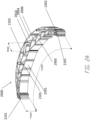
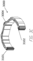
- Figures 3A-4C illustrate an embodiment of a clamping structure 3000 having a cell configuration as described above.
- Figures 3A-C illustrate perspective views of the transformation of an embodiment of the clamping structure 3000 before application of negative pressure, the clamping structure 3200 during collapse with or without negative pressure, and the clamping structure 3400 after collapse with or without negative pressure.
- the curvature of the elongate strips of the clamping structure increases and the distance between first end 3101 and the second end 3102 decreases.
- the first end and the second end completely touches each other upon the collapse of the clamping structure.
- the distance between the first end and the second end after collapse is less than 80%, 70%, 60%, 50%, 40%, 30%, 20%, or 10% of the original distance between the first end and the second end.
- the clamping structure may grab the one or more object.
- the clamping structure may pull objects attached to the first end and the second end closer.
- FIGS 3D-F illustrate a top view of the embodiment of Figures 3A-C .
- each collapsible cell 3004 may have four sides, and each intersection between an intervening member(s) and/or elongated strip(s) may be modeled via pin-joints 3032.
- the clamping structure 3000 may be modeled to collapse from an open state to a semi-collapsed state 3200, and to a fully collapsed state 3400.
- Figures 3G-H are photographs of an embodiment of the clamping structure 3000 before negative pressure is applied, and the clamping structure 3400 after negative pressure is applied.
- the process of determining the optimal shape, size, and location of the elongate strips, intervening members, and cells for clamping may be facilitated by modeling the clamping structure as a mirrored pattern on opposite sides of a mirror line 3050 (which may also be referred to as the transverse axis, perpendicular to a length of the clamping structure), thereby making the curve and collapse of the clamping structure symmetrical.
- the mirror line may be located in any suitable location within the clamping structure, such as diagonally across the clamping structure. In certain embodiments, this method may lead to large diamond-shaped cells near the center line.
- These large diamond-shaped structures 3052 may be further subdivided to further support the clamping structure by including smaller diamond shapes 3054 within larger shapes.
- these smaller shapes 3054 within a larger shape 3052 may comprise any shape disclosed herein this section or elsewhere in the specification.
- the larger cells may be further subdivided by two smaller shapes, three smaller shapes, four smaller shapes, or more than four smaller shapes.
- the clamping structure may contain multiple mirror lines, thereby having multiple subsections that are symmetrical or different.
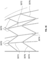
- elongate strip cell sections were progressively lengthened (a4 > a3 > a2 > a1) towards the horizontal mirror line 3050, thereby achieving a curve following the curve of elongated strips in the clamping structure while preventing any of the intervening members 3062 from becoming perpendicular to the elongate strips 3064 (i.e. having an internal angle of 90 degrees).
- a value for b1 may be chosen, at which point an arbitrary offset value x may also be chosen to ease the construction of the various cell geometries.
- values for b1-b4 may be calculated 3068.
- Using calculated values derived from equations 3068 for the various walls of the individual cells allows for the design of a clamping structure that collapses completely, such as those depicted in Figures 3A-F .
- a method for generating a clamping structure design may include steps to speed up the initial geometry construction. For example, if all members from left to right are in a specific row, as visualized by intervening members 3076 in Figure 4C , a pattern then emerges where alternating vertical members are also the same length. Walls of the same length are indicated by their respective labels 3070, 3072, 3074, and 3076. Once the initial design is generated then individual cells may be modified by lengthening, shortening, removing or inserted according to the formulas of Figure 4B to achieve the desired shape of the overall clamping structure.
- FIGS 5A-B illustrate an embodiment of a clamping structure 4000, similar to the clamping structures disclosed previously in Figures 2A-2C , 3A-B , and 4A-C .
- clamping structure 4000 comprises inner segment 4100 and a detachable segment 4200.
- the detachable segment 4200 at least partially surrounds the inner segment 4100.
- each of the segments may have a crescent shape.
- the detachable segment of the clamping structure 4200 may be removed from the overall structure to form a smaller clamping structure such as the inner segment 4100.
- the detachable sections of the clamping structures of Figures 5A-7B may be removed in any suitable direction.
- the clamping structure may be configured such that the detachable section(s) may be removed horizontally within an x-y plane parallel to the longest dimension of the clamping structure.
- the clamping structure may be configured such that detachable sections may be removed in a vertical direction in the z axis, perpendicular to the x-y plane.
- the clamping structure may have at least one detachable section removable in a horizontal direction and one section removable in a vertical direction.
- the detachable section(s) may be attached to the clamping structure in such a manner that the detachable section(s) may only be removed in a single direction, such as by the use of slots and/or channels as the attachment and receiving elements.
- the clamping structure segments may be cut from the clamping structure 4000 to produce a smaller structure.
- the clamping structure may have pre-cuts along the shape of the segments 4100 and 4200 to allow the segments to be tearable and easily removed by hand from the clamping structure.
- the detachable segments may be adhered to the remainder of the clamping structure via adhesive, Velcro ® , or other suitable adhesive means.
- the removable sections may be held together by the tightness of the structures squeezing together and/or via friction.
- magnets and/or suction cups may be used to keep the segments together.
- detachable segments 4200 may comprise one or more attachment elements 4406, which may be in the form of prongs, hooks, tongues, screws, nails, or other suitable attachment means.
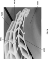
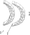
- Figures 5C-D are photographs of such embodiments.
- the attachment elements 4406 attach to receiving elements 4408 of the inner segment 4100 which may be in the form of grooves, holes, windows, or any suitable means.
- Figure 5C-D depicts an embodiment of a clamping structure 4000 where the attachment elements 4406 are tongues which fit into the receiving elements, which are grooves 4408.
- detachable segments and inner segment may comprise both attachment elements and receiving elements.
- a detachable segment may comprise attachment elements on one side and receiving elements on the opposite side to allow the detachable elements to be stacked one after another.
- segments may comprise at least about 1, 2, 3, 4, 5, 6, 7, 8, 10, 15, 20, 30, or more than 30 attachment elements. In some embodiments, segments may comprise at least about 1, 2, 3, 4, 5, 6, 7, 8, 10, 15, 20, 30, or more than 30 receiving elements.
- Figure 5E depicts an embodiment of a clamping structure 4500 where the attachment elements 4506 are prongs.
- Figure 5F depicts an embodiment of a clamping structure 4600 where the attachment elements 4602 are claws which fit into the receiving elements, which are grooves 4604.
- Figure 5G depicts an embodiment of a clamping structure 4700 where the attachment elements 4702 are hooked and the receiving elements are configured to receive the hooks.
- Figure 5H depicts an embodiment of a clamping structure 4800 where adhesive 4802 may be applied to certain areas of the detachable segments for adhesion to the outer surfaces of other detachable segments or the inner segment. Adhesive may also be applied to the inner segment.
- Figure 5I depicts a clamping structure 4900 similar to the clamping structures of Figures 5A-5H .
- the detachable segments 4904 comprise extended cells 4906 which fit into recesses 4908 of inner segment 4902 or another detachable segment 4904.
- the extended cells are configured to snap fit into the recesses, such that the different segments can be separated from one another by the application of force. For example, separation can occur by the application of force by a user.
- the detachable segments such as those disclosed above in relation to Figures 5A-I may be packaged within a separate kit from the clamping structure.
- the separately packaged detachable segments may comprise attachment elements and/or receiving elements such as those disclosed herein this section or elsewhere in the specification. Such separately packaged detachable segments may then be added to main clamping structure to increase the size and/or alter the shape of the clamping structure.
- the separate kit(s) of detachable segments may contain one detachable segment, two detachable segments, three detachable segments, four detachable segments, five detachable segments, or more than five detachable segments.
- the detachable segments may be in the form of a crescent.
- Clamping structures may collapse in different fashion depending on the shape of the clamping structure. For example, in some embodiments, when the curvature of a clamping structure increases upon collapse of cells, the increase of the curvature is greater when the difference between the length of the concave side and the convex side is greater.
- the difference between the length of the concave side and the convex side may be adjusted with the installation or removal of detachable segments. For example, in Figures 5A-B , the difference between the length of the concave side and the convex side is greater in the clamping structure 4000 than in the inner segment 4100.
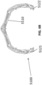
- Figures 6A-7B compares the clamping of an embodiment of the clamping structure 5000 and the inner segment 5100 without the detachable segment 5200.
- the curvature of the concave side 5110 and the distance between the first end 5121 and the second end 5122 is identical as shown in Figures 6A and 7A .
- the clamping structure with the detachable segment installed which is illustrated in Figure 7B shows greater degree of transformation than the clamping structure without detachable segment which is illustrated in Figure 6B .
- Photographs of such embodiment are shown in Figures 7C-D .
- an embodiment of object 5500 subject to clamping of 5000 is shown.
- the concave side 5110 of the clamping structure 5000 in Figure 7D would form a relatively more intimate contact with the contoured object with 5500 than the collapsed clamping structure 5100 of Figure 6B would have formed. Therefore, where such proper fit of curvature between the concave side and contoured object is desired, the control of curvature by installing and removing detachable segments may be useful.
- the clamping structure may show gradually greater clamping activity as one, two, three and more detachable segments are installed, so that the user of the clamping structure may adjust the degree of clamping activity by removing or installing the detachable structure.
- the clamping structure may be designed to clamp in smaller degree with the detachable segments installed.
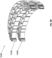
- Figure 8A depicts an embodiment of a clamping device 7000, comprising 7200 and 7400, similar to those disclosed elsewhere in the specification, such as in relation to Figures 2A-7D .
- the clamping structures 7200 and 7400 may be stacked one atop the other to provide a clamping device 7000 with greater height. With greater height, the stacked clamping device will have wider side walls and may be applied to a larger object.
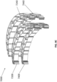
- Figure 8B illustrates an exploded view of such embodiments.
- the clamping device may comprise two stackable clamping structures, three stackable clamping structures, four stackable clamping structures, five stackable clamping structures, or more than five stackable clamping structures. In some embodiments, all stackable clamping structures have the same size.
- stackable clamping structures have different sizes. Similar to the detachable segments described above, the stackable clamping structures may be packaged separately as kits. In some embodiments, the stackable clamping structures contain attachment elements and/or receiving elements, such as those disclosed herein this section or elsewhere in the specification, allowing the stackable clamping structures to be attached to one another. In some embodiments, the stacked clamping device has similar collapsing behavior to that of individual clamping devices.
- stackable clamping structures may further comprise detachable elements 7240 and 7440, so that user can adjust both width and height of the clamping device.
- detachable elements 7240 and 7440 so that user can adjust both width and height of the clamping device.
- adjusting the width by installing or removing the detachable elements may affect the collapsing behavior of the clamping structure.
- Figures 8D and 8E are photographs of an embodiment of stackable clamping structures 7000 which is similar with the stackable clamping structures described in relation to Figures 8A-8C and applied around a spherical object 7900.
- Figures 9A-9B Pincer Device Having a Clamping Structure
- FIGS 9A-B illustrate schematic view of an embodiment of a pincer having a clamping structure.
- a pincer 9000 contains a clamping structure 9100, a flexible membrane 9200 and a tube 9300.
- the clamping structure 9100 may be identical or similar with any clamping structures described in relation with Figures 2A-8E or elsewhere in the specification.
- the clamping structure 9100 may have a fluid path or notches (not shows) between cells, such that negative pressure can propagate through the fluid path or notches.
- the tube 9300 may be configured to deliver negative pressure to the clamping structure 9100.
- the tube 9300 may be fluidically connected with a source of negative pressure, and in some embodiments, the source of negative pressure may be integrated or mounted on the tube 9300.
- the pincer 9000 may have additional conduits to deliver negative pressure to the clamping structure 9100.
- the tube 9300 may be constructed from relatively rigid material and maintain its structure, so that the tube 9300 may be utilized as a grip or stick which the user of the pincer can hold.
- the flexible membrane 9200 may cover the clamping structure 9100 and form a fluid-tight seal with the tube 9300.
- the membrane 9200 may include a port, such that the tube 9300 can be connected with the membrane 9200.
- the flexible membrane 9200 may be constructed from a flexible film material or any other suitable materials. In some embodiments, the flexible membrane 9200 may only cover the top end and the bottom end of the cells, forming a fluid tight seal with the clamping structure.
- Figure 9B illustrates another embodiment of a pincer 9500.
- the pincer 9500 may be similar with the pincer 9000 of Figure 9A .
- the pincer 9500 may contain a tube 9700 directly integrated with a clamping structure 9600.
- the tube 9700 may have one or more air holes 9800 which is configured to fluidically connect the tube 9700 with one or more cells of 9600.
- the clamping structure 9600 may have a fluid path or notches (not shows) between cells, such that negative pressure can further propagate through the fluid path or notches.
- the tube 9700 and the clamping structure 9600 could be constructed as a single piece.
- the pincer 9500 may further include a flexible membrane which encases the clamping structure and form a fluid tight seal around the clamping structure 9600.
- the flexible membrane may only cover the top end and the bottom end of each cells, forming fluid tight seal with the clamping structure.
- clamping structures shown in Figures 2A-8D are singlecurved structures which will increase their curvature upon collapse under negative pressure
- a straight-line shaped collapsible structure having similar cell configuration with clamping structures described in relation with Figures 2A-8D may bend along its length upon application of negative pressure.
- Compound shapes may also be provided by combining multiple collapsible structures similar with clamping structures described in relation with Figures 2A-8D together in different orientations.
- the collapsible structure may be enclosed within a cover member to form an enclosed, airtight space. Application of negative pressure to the enclosed space can cause the collapsible structure to collapse from the initial shape to the collapsed shape.
- a more complex structure may constructed from more rigid parts (e.g., beams, skeletons) and collapsible structures similar with clamping structures described in relation with Figures 2A-8D which connect and act as joints of more rigid parts, such that the overall shape of the structure transforms in predetermined fashion upon application of negative pressure.
- more rigid parts e.g., beams, skeletons
- collapsible structures similar with clamping structures described in relation with Figures 2A-8D which connect and act as joints of more rigid parts, such that the overall shape of the structure transforms in predetermined fashion upon application of negative pressure.
- the terms “generally parallel” and “substantially parallel” refer to a value, amount, or characteristic that departs from exactly parallel by less than or equal to 15 degrees, 10 degrees, 5 degrees, 3 degrees, 1 degree, 0.1 degree, or otherwise.
Landscapes
- Health & Medical Sciences (AREA)
- Heart & Thoracic Surgery (AREA)
- General Health & Medical Sciences (AREA)
- Engineering & Computer Science (AREA)
- Biomedical Technology (AREA)
- Life Sciences & Earth Sciences (AREA)
- Animal Behavior & Ethology (AREA)
- Vascular Medicine (AREA)
- Public Health (AREA)
- Veterinary Medicine (AREA)
- Anesthesiology (AREA)
- Hematology (AREA)
- Apparatus Associated With Microorganisms And Enzymes (AREA)
Claims (17)
- Eine Einrichtung zur Verwendung mit Unterdruck, beinhaltend:eine Spannstruktur (2000, 4000, 7000) mit einem ersten Ende (2201), einem zweiten Ende (2202), einer Länge, die sich von dem ersten Ende (2201) und dem zweiten Ende (2202) erstreckt, einer Breite quer zu der Länge, die sich entlang einer zentralen Querachse der Spannstruktur (2000, 4000, 7000) erstreckt, und einer Höhe quer zu der Länge und der Breite, wobei die Länge und Breite größer sind als die Höhe, wobei die Spannstruktur (2000, 4000, 7000) Folgendes beinhaltet:eine erste Seite (2101) und eine zweite Seite (2102), die sich entlang der Spannstruktur (2000, 4000, 7000) von dem ersten Ende (2201) zu dem zweiten Ende (2202) auf im Wesentlichen parallele Art erstrecken, wobei die erste Seite (2202) der zweiten Seite (2102) gegenüberliegt;eine Vielzahl von länglichen Streifen (2301, 2302), die sich entlang der Spannstruktur (2000, 4000, 7000) von dem ersten Ende (2201) zu dem zweiten Ende (2202) erstrecken, wobei die Vielzahl von länglichen Streifen (2301, 2302) zwei äußerste längliche Streifen (2301, 2302) beinhalten, die die erste Seite (2101) und die zweite Seite (2102) definieren;eine Vielzahl von zwischenliegenden Bauteilen (2010), die die Vielzahl von länglichen Streifen (2301, 2302) verbinden, wobei die Vielzahl von zwischenliegenden Bauteilen (2010) konfiguriert sind, um relativ zu den Streifen (2301, 2302) zu schwenken, um der Vielzahl von länglichen Streifen (2301, 2302) zu ermöglichen, relativ zueinander zusammenzuklappen; undeine Vielzahl von Zellen (2004), die Seite an Seite in einer horizontalen Ebene parallel zu der Länge und Breite der Spannstruktur (2000, 4000, 7000) bereitgestellt sind, wobei jede Zelle (2004) durch eine Vielzahl von Wänden definiert ist, die entweder durch die länglichen Streifen (2301, 2302) oder die zwischenliegenden Bauteile (2010) gebildet sind, wobei jede Zelle (2004) ein oberes Ende und ein unteres Ende mit einer Öffnung aufweist, die sich durch das obere und untere Ende hindurch erstreckt;wobei die Spannstruktur (2000, 4000, 7000) derart konfiguriert ist, dass, bei Verwendung, beim Zusammenklappen der Vielzahl von Zellen (2004), die Krümmung der Vielzahl von länglichen Streifen (2301, 2302) innerhalb der horizontalen Ebene entlang der Länge der Spannstruktur (2000, 4000, 7000) zunimmt und die Distanz zwischen dem ersten Ende (2201) und dem zweiten Ende (2202) abnimmt.
- Einrichtung gemäß Anspruch 1, wobei die erste Seite (2101) eine konkave Seite ist und die zweite Seite (2102) eine konvexe Seite ist und die konkave Seite bezüglich der Spannstruktur (2000, 4000, 7000) konkav gekrümmt oder gebogen ist und die konvexe Seite bezüglich der Spannstruktur (2000, 4000, 7000) konvex gekrümmt oder gebogen ist.
- Einrichtung gemäß Anspruch 1 oder 2, wobei die Länge der Spannstruktur (2000, 4000, 7000) größer als die Breite der Spannstruktur (2000, 4000, 7000) ist.
- Einrichtung gemäß einem der Ansprüche 1-3, wobei die Spannstruktur (2000, 4000, 7000) um die zentrale Querachse herum symmetrisch ist.
- Einrichtung gemäß einem der Ansprüche 1-4, wobei die erste Seite (2101) und die zweite Seite (2102) sich in Richtung des ersten und zweiten Endes (2201, 2202) verjüngen.
- Einrichtung gemäß einem der Ansprüche 1-5, wobei die Spannstruktur (2000, 4000, 7000) mindestens teilweise halbmondförmig ist.
- Einrichtung gemäß einem der Ansprüche 1-6, wobei die Vielzahl von länglichen Streifen ferner mindestens einen länglichen Streifen (2006) beinhaltet, der zwischen der ersten Seite (2101) und der zweiten Seite (2102) positioniert ist.
- Einrichtung gemäß einem der Ansprüche 1-7, wobei jeder der länglichen Streifen (2301, 2302, 2006) auf im Wesentlichen parallele Art angeordnet ist.
- Einrichtung gemäß einem der Ansprüche 1-8, wobei mindestens einige der Zellen (2004) diamantenförmig sind; wahlweise
wobei mindestens einige der diamantenförmigen Zellen (2020) aus größeren diamantenförmigen Zellen (2022) aufgeteilt sind. - Einrichtung gemäß einem der Ansprüche 1-9, wobei mindestens einige der Zellen (2004) parallelepipedförmig sind.
- Einrichtung gemäß einem der Ansprüche 1-10, wobei die Längen der Zellen (2004) entlang eines länglichen Streifens (2301, 2302, 2006) in Richtung des ersten Endes (2201) und des zweiten Endes (2202) progressiv kürzer sind.
- Einrichtung gemäß einem der Ansprüche 1-11, wobei die Spannstruktur (4000) ein oder mehrere ablösbare Segmente (4200) beinhaltet; wahlweise wobei das eine oder die mehreren Segmente (4200) ferner Befestigungselemente (4406) beinhalten.
- Einrichtung gemäß Anspruch 12, wobei die Spannstruktur (4000) ferner ein inneres Segment (4100) beinhaltet, das mindestens teilweise von einem oder mehreren ablösbaren Segmenten (4200) umgeben ist; wahlweise
wobei das innere Segment (4100) ferner Aufnahmeelemente (4408) beinhaltet, die konfiguriert sind, um Befestigungselemente (4406) des einen oder der mehreren ablösbaren Segmente (4200) aufzunehmen. - Einrichtung gemäß einem der Ansprüche 1-13, beinhaltend eine erste Spannstruktur (7400) und eine zweite Spannstruktur (7200); wahlweise wobei die zweite Spannstruktur (7200) an einer Oberseite der ersten Spannstruktur (7400) befestigt ist.
- Einrichtung gemäß Anspruch 14, wobei die zweite Spannstruktur (7200) Aufnahmeelemente beinhaltet, die konfiguriert sind, um Befestigungselemente der ersten Spannstruktur (7400) aufzunehmen.
- Einrichtung gemäß einem der Ansprüche 1-15, ferner beinhaltend eine Unterdruckquelle.
- Einrichtung gemäß einem der Ansprüche 1-16, ferner beinhaltend ein Abdecktuch; wahlweise
ferner beinhaltend einen Anschluss, wobei der Anschluss konfiguriert ist, um Unterdruck durch ein Abdecktuch hindurch zu übertragen, das über der Struktur platziert ist.
Applications Claiming Priority (2)
| Application Number | Priority Date | Filing Date | Title |
|---|---|---|---|
| US201762518718P | 2017-06-13 | 2017-06-13 | |
| PCT/EP2018/065398 WO2018229010A1 (en) | 2017-06-13 | 2018-06-11 | Collapsible structure and method of use |
Publications (2)
| Publication Number | Publication Date |
|---|---|
| EP3638169A1 EP3638169A1 (de) | 2020-04-22 |
| EP3638169B1 true EP3638169B1 (de) | 2024-11-13 |
Family
ID=62599606
Family Applications (1)
| Application Number | Title | Priority Date | Filing Date |
|---|---|---|---|
| EP18731062.8A Active EP3638169B1 (de) | 2017-06-13 | 2018-06-11 | Zusammenklappbare struktur und anwendungsverfahren |
Country Status (3)
| Country | Link |
|---|---|
| US (2) | US11324876B2 (de) |
| EP (1) | EP3638169B1 (de) |
| WO (1) | WO2018229010A1 (de) |
Families Citing this family (2)
| Publication number | Priority date | Publication date | Assignee | Title |
|---|---|---|---|---|
| JP7179022B2 (ja) * | 2017-06-13 | 2022-11-28 | スミス アンド ネフュー ピーエルシー | 創傷閉鎖装置および使用方法 |
| EP3658090B1 (de) * | 2017-07-27 | 2021-11-10 | Smith & Nephew PLC | Anpassbare wundverschlussvorrichtung |
Family Cites Families (258)
| Publication number | Priority date | Publication date | Assignee | Title |
|---|---|---|---|---|
| US3194239A (en) | 1963-01-16 | 1965-07-13 | Cornelius J P Sullivan | Suture provided with radiopaque free metal |
| US3789851A (en) | 1971-07-01 | 1974-02-05 | H Leveen | Wound splints |
| JPS5636960A (en) | 1979-08-31 | 1981-04-10 | Matsuda Ika Kogyo | Suturing gut for medical treatment |
| SE429197B (sv) | 1981-10-14 | 1983-08-22 | Frese Nielsen | Anordning for behandling av sar |
| US4467805A (en) | 1982-08-25 | 1984-08-28 | Mamoru Fukuda | Skin closure stapling device for surgical procedures |
| DK149601C (da) | 1984-01-23 | 1987-02-02 | Coloplast As | Trykaflastende bandage |
| JPS6257560A (ja) | 1985-09-06 | 1987-03-13 | 中興化成工業株式会社 | 医療用縫合糸 |
| US4815468A (en) | 1987-01-09 | 1989-03-28 | Annand David S | Sutureless closure |
| US5176663A (en) | 1987-12-02 | 1993-01-05 | Pal Svedman | Dressing having pad with compressibility limiting elements |
| US5409472A (en) | 1989-08-03 | 1995-04-25 | Smith & Nephew Plc | Adhesive polymeric foam dressings |
| US5264218A (en) | 1989-10-25 | 1993-11-23 | C. R. Bard, Inc. | Modifiable, semi-permeable, wound dressing |
| SU1818103A1 (en) | 1991-06-21 | 1993-05-30 | Tsnii Travmatologii I Ortopedi | Device for treatment of contaminated wounds |
| US5636643A (en) | 1991-11-14 | 1997-06-10 | Wake Forest University | Wound treatment employing reduced pressure |
| FR2691923B1 (fr) | 1992-06-04 | 1994-09-09 | Europ Propulsion | Structure en nid d'abeilles en matériau composite thermostructural et son procédé de fabrication. |
| US5376067A (en) | 1992-10-28 | 1994-12-27 | Daneshvar; Yousef | Pressure bandages and dressings |
| US5584859A (en) | 1993-10-12 | 1996-12-17 | Brotz; Gregory R. | Suture assembly |
| US5423857A (en) | 1993-11-02 | 1995-06-13 | Ethicon, Inc. | Three piece surgical staple |
| US5695777A (en) | 1994-05-10 | 1997-12-09 | Medtronic, Inc. | Absorptive wound dressing for wound healing promotion |
| US5512041A (en) | 1994-10-07 | 1996-04-30 | Scott Health Care | Wound dressing for promoting moist wound healing |
| US5562107A (en) | 1995-09-27 | 1996-10-08 | Hollister Incorporated | Reclosable wound cover |
| US7771402B2 (en) | 1996-07-11 | 2010-08-10 | PulseCare Medical | Wound irrigation containment arrangement |
| US8353948B2 (en) | 1997-01-24 | 2013-01-15 | Celonova Stent, Inc. | Fracture-resistant helical stent incorporating bistable cells and methods of use |
| DE29924318U1 (de) | 1999-01-14 | 2002-09-19 | Fleischmann, Wilhelm, Dr.med., 74321 Bietigheim-Bissingen | Verbandsmaterial |
| AU774512B2 (en) | 1999-04-02 | 2004-07-01 | Kci Licensing, Inc. | Vacuum assisted closure system with heating and cooling provision |
| US6991643B2 (en) | 2000-12-20 | 2006-01-31 | Usgi Medical Inc. | Multi-barbed device for retaining tissue in apposition and methods of use |
| FR2801188B1 (fr) | 1999-11-22 | 2002-11-08 | Didier Detour | Dispositif permettant la fermeture non traumatique, sans suture, des bords ouverts d'une plaie de la peau d'un mammifere |
| US6794554B2 (en) | 2000-02-01 | 2004-09-21 | Ferris Pharmaceuticals, Inc. | Wound packing material |
| US6566575B1 (en) | 2000-02-15 | 2003-05-20 | 3M Innovative Properties Company | Patterned absorbent article for wound dressing |
| US6548727B1 (en) | 2000-02-17 | 2003-04-15 | 3M Innovative Properties Company | Foam/film composite medical articles |
| US6977323B1 (en) | 2000-02-17 | 2005-12-20 | 3M Innovative Properties Company | Foam-on-film medical articles |
| GB0011202D0 (en) | 2000-05-09 | 2000-06-28 | Kci Licensing Inc | Abdominal wound dressing |
| EP1289431B1 (de) | 2000-05-19 | 2009-01-14 | Coapt Systems, Inc. | Angleichvorrichtung für gewebe |
| US7619130B2 (en) | 2000-07-18 | 2009-11-17 | Coloplast A/S | Multi-layer wound dressing formed as a single unit |
| US6767356B2 (en) | 2000-09-01 | 2004-07-27 | Angiolink Corporation | Advanced wound site management systems and methods |
| US7066182B1 (en) | 2000-09-27 | 2006-06-27 | 3M Innovative Properties Company | Conformable adhesive wound closures |
| US6855135B2 (en) | 2000-11-29 | 2005-02-15 | Hill-Rom Services, Inc. | Vacuum therapy and cleansing dressing for wounds |
| US6685681B2 (en) | 2000-11-29 | 2004-02-03 | Hill-Rom Services, Inc. | Vacuum therapy and cleansing dressing for wounds |
| US6503208B1 (en) | 2000-12-05 | 2003-01-07 | Holtech Medical | Method and apparatus for the measurement of intra-abdominal pressure |
| US7700819B2 (en) | 2001-02-16 | 2010-04-20 | Kci Licensing, Inc. | Biocompatible wound dressing |
| WO2002092783A2 (en) | 2001-05-15 | 2002-11-21 | Children's Medical Center Corporation | Methods and apparatus for application of micro-mechanical forces to tissues |
| EP2572674A3 (de) | 2001-07-06 | 2013-08-07 | Syntach AG | Implantierbare Blutdruckreglervorrichtung |
| US6592608B2 (en) | 2001-12-07 | 2003-07-15 | Biopsy Sciences, Llc | Bioabsorbable sealant |
| US7004915B2 (en) | 2001-08-24 | 2006-02-28 | Kci Licensing, Inc. | Negative pressure assisted tissue treatment system |
| US6787682B2 (en) | 2001-11-05 | 2004-09-07 | Hollister Incorporated | Absorbent foam wound dressing |
| DE10209122B4 (de) | 2002-03-01 | 2006-04-13 | Fleischmann, Wilhelm, Dr.med. | Instrument zur Gewebedehnung der Haut |
| US8407065B2 (en) | 2002-05-07 | 2013-03-26 | Polyremedy, Inc. | Wound care treatment service using automatic wound dressing fabricator |
| AU2003233510A1 (en) | 2002-05-07 | 2003-11-11 | Polyremedy Llc | Method for treating wound, dressing for use therewith and apparatus and system for fabricating dressing |
| GB2389794A (en) | 2002-06-19 | 2003-12-24 | Johnson & Johnson Medical Ltd | Wound dressing with variable shape |
| US7351250B2 (en) | 2002-08-21 | 2008-04-01 | Kci Licensing, Inc. | Circumferential medical closure device and method |
| JP2005536275A (ja) | 2002-08-21 | 2005-12-02 | ヒル−ロム サービシズ,インコーポレイテッド | 創傷閉鎖を防止するための創傷用パッキング |
| US7381211B2 (en) | 2002-08-21 | 2008-06-03 | Kci Licensing, Inc. | Medical closure screen device and method |
| US8062331B2 (en) | 2002-08-21 | 2011-11-22 | Kci Licensing, Inc. | Internal and external medical closure screen systems and methods |
| US7815616B2 (en) | 2002-09-16 | 2010-10-19 | Boehringer Technologies, L.P. | Device for treating a wound |
| US7625362B2 (en) | 2003-09-16 | 2009-12-01 | Boehringer Technologies, L.P. | Apparatus and method for suction-assisted wound healing |
| GB0224986D0 (en) | 2002-10-28 | 2002-12-04 | Smith & Nephew | Apparatus |
| US7976519B2 (en) | 2002-12-31 | 2011-07-12 | Kci Licensing, Inc. | Externally-applied patient interface system and method |
| US6838589B2 (en) | 2003-02-19 | 2005-01-04 | 3M Innovative Properties Company | Conformable wound dressing |
| US7112177B2 (en) | 2003-03-04 | 2006-09-26 | Wolfe Tory Medical, Inc. | Apparatus for monitoring intra-abdominal pressure |
| US7942866B2 (en) | 2003-08-28 | 2011-05-17 | Boehringer Technologies, L.P. | Device for treating a wound |
| US7361184B2 (en) | 2003-09-08 | 2008-04-22 | Joshi Ashok V | Device and method for wound therapy |
| NL1025938C2 (nl) | 2003-09-17 | 2005-03-18 | Broockeville Corp N V | Wonddrainage-inrichting. |
| GB0325129D0 (en) | 2003-10-28 | 2003-12-03 | Smith & Nephew | Apparatus in situ |
| GB0325120D0 (en) | 2003-10-28 | 2003-12-03 | Smith & Nephew | Apparatus with actives |
| US7252870B2 (en) | 2003-12-31 | 2007-08-07 | Kimberly-Clark Worldwide, Inc. | Nonwovens having reduced Poisson ratio |
| GB0403969D0 (en) | 2004-02-24 | 2004-03-31 | Huntleigh Technology Plc | Tissue treatment device |
| US7754937B2 (en) | 2004-03-18 | 2010-07-13 | Boehringer Technologies, L.P. | Wound packing material for use with suction |
| US7909805B2 (en) | 2004-04-05 | 2011-03-22 | Bluesky Medical Group Incorporated | Flexible reduced pressure treatment appliance |
| US7951124B2 (en) | 2004-04-13 | 2011-05-31 | Boehringer Technologies, Lp | Growth stimulating wound dressing with improved contact surfaces |
| GB0424046D0 (en) | 2004-10-29 | 2004-12-01 | Smith & Nephew | Apparatus |
| GB0508528D0 (en) | 2005-04-27 | 2005-06-01 | Smith & Nephew | SAI with macrostress |
| GB0409291D0 (en) | 2004-04-27 | 2004-06-02 | Smith & Nephew | Apparatus with stress |
| GB0508531D0 (en) | 2005-04-27 | 2005-06-01 | Smith & Nephew | Sai with ultrasound |
| US20050267424A1 (en) | 2004-05-17 | 2005-12-01 | Elof Eriksson | Wound chamber with remote access portal |
| US20060020269A1 (en) | 2004-07-20 | 2006-01-26 | Eric Cheng | Device to aid in stone removal and laser lithotripsy |
| US7364145B2 (en) | 2004-09-08 | 2008-04-29 | Equipment Solutions, Inc | High stiffness flexure |
| US7455681B2 (en) | 2004-09-13 | 2008-11-25 | Wound Care Technologies, Llc | Wound closure product |
| US8491503B2 (en) | 2004-09-29 | 2013-07-23 | Covidien Lp | Intrauterine pressure catheter interface cable system |
| US7315183B2 (en) | 2004-11-22 | 2008-01-01 | Texas Instruments Incorporated | Single-supply voltage translator input having low supply current |
| JP4560415B2 (ja) | 2005-01-20 | 2010-10-13 | ユニ・チャーム株式会社 | 吸収性物品 |
| GB2423019A (en) | 2005-02-09 | 2006-08-16 | Ind Ltd Ak | Wound dressing and wound treatment system including the wound dressing |
| DE102005007016A1 (de) | 2005-02-15 | 2006-08-24 | Fleischmann, Wilhelm, Dr.med. | Vorrichtung zur Behandlung von Wunden |
| WO2006110197A2 (en) | 2005-03-03 | 2006-10-19 | Icon Medical Corp. | Polymer biodegradable medical device |
| US8067662B2 (en) | 2009-04-01 | 2011-11-29 | Aalnex, Inc. | Systems and methods for wound protection and exudate management |
| US8415523B2 (en) | 2005-04-16 | 2013-04-09 | Aalnex, Inc. | Secondary wound dressings for securing primary dressings and managing fluid from wounds, and methods of using same |
| US7857806B2 (en) | 2005-07-14 | 2010-12-28 | Boehringer Technologies, L.P. | Pump system for negative pressure wound therapy |
| US8337411B2 (en) | 2005-07-14 | 2012-12-25 | C. R. Bard, Inc. | Intra-abdominal pressure monitoring system |
| US7438705B2 (en) | 2005-07-14 | 2008-10-21 | Boehringer Technologies, L.P. | System for treating a wound with suction and method detecting loss of suction |
| JP2009506878A (ja) | 2005-09-07 | 2009-02-19 | タイコ ヘルスケア グループ リミテッド パートナーシップ | マイクロポンプを有する自蔵創傷手当て |
| CA2619925A1 (en) | 2005-09-07 | 2007-03-15 | Tyco Healthcare Group Lp | Wound dressing with vacuum reservoir |
| JP2007126341A (ja) | 2005-11-07 | 2007-05-24 | Toshiba Corp | 異方性多孔質材料 |
| EP2010245B1 (de) | 2005-11-21 | 2015-10-14 | Joshua David Smith | Wundpflegesystem |
| DE202005019670U1 (de) | 2005-12-14 | 2006-04-27 | Riesinger, Birgit | Wundbehandlungsvorrichtung mit elastisch verformbarem Unterdruckerzeugungselement |
| US7622629B2 (en) | 2005-12-15 | 2009-11-24 | Aalnex, Inc. | Wound shield for exudate management |
| US7863495B2 (en) | 2006-01-12 | 2011-01-04 | Aalnex, Inc. | Dressing substrate |
| US20100081983A1 (en) | 2005-12-23 | 2010-04-01 | Biosara Corporation | Wound guard bandage |
| US7605299B2 (en) | 2005-12-23 | 2009-10-20 | Biosara Corporation | Wound guard bandage |
| JP5263882B2 (ja) | 2006-02-07 | 2013-08-14 | コビディエン・リミテッド・パートナーシップ | 外科用創傷包帯 |
| US20070213597A1 (en) | 2006-03-01 | 2007-09-13 | Wooster Nicholas H | Surgical retractor frame system |
| CA2648799A1 (en) | 2006-04-25 | 2007-11-01 | Coloplast A/S | An adhesive wafer |
| US7779625B2 (en) | 2006-05-11 | 2010-08-24 | Kalypto Medical, Inc. | Device and method for wound therapy |
| US7615036B2 (en) | 2006-05-11 | 2009-11-10 | Kalypto Medical, Inc. | Device and method for wound therapy |
| WO2007142688A1 (en) | 2006-06-02 | 2007-12-13 | Bengtson Bradley P | Assemblies, systems, and methods for vacuum assisted internal drainage during wound healing |
| WO2008021306A2 (en) | 2006-08-15 | 2008-02-21 | Bio-Innovative Operations, Inc. | Computer adjusted pressure wound care devices, systems & methods |
| EP2068798A4 (de) | 2006-08-30 | 2009-12-16 | Southeastern Medical Technolog | Verfahren, zusammensetzungen und vorrichtungen zur wundbehandlung mit anderem als dem atmosphärischen druck |
| BRPI0714993A2 (pt) | 2006-09-19 | 2013-07-30 | Kci Licensing Inc | sistema de tratamento com pressço reduzida e mÉtodo de tratamento de um sÍtio de tecido |
| EP2081528B1 (de) | 2006-09-26 | 2018-11-14 | T.J. Smith & Nephew, Limited | Gitterverband |
| US9820888B2 (en) | 2006-09-26 | 2017-11-21 | Smith & Nephew, Inc. | Wound dressing |
| GB0903032D0 (en) | 2009-02-24 | 2009-04-08 | Smith & Nephew | Drapeable wound dressing |
| US20080243096A1 (en) | 2006-10-05 | 2008-10-02 | Paul Svedman | Device For Active Treatment and Regeneration of Tissues Such as Wounds |
| EP3473293A1 (de) | 2006-10-13 | 2019-04-24 | KCI Licensing, Inc. | Unterdruckabgabesystem mit manuell betätigter pumpe zur behandlung leichter wunden |
| KR100788356B1 (ko) | 2006-10-26 | 2008-01-02 | 동부일렉트로닉스 주식회사 | 전압차가 큰 레벨 변환이 가능한 단일 전원 레벨 변환기 |
| US8353931B2 (en) | 2006-11-02 | 2013-01-15 | Covidien Lp | Long term bioabsorbable barbed sutures |
| US7931774B2 (en) | 2006-11-06 | 2011-04-26 | 3M Innovative Properties Company | Acrylic adhesives containing an amine plasticizer |
| US8030534B2 (en) | 2006-11-28 | 2011-10-04 | Boehringer Technologies, L.P. | Tunnel dressing for use with negative pressure wound therapy system |
| ATE539721T1 (de) | 2006-11-30 | 2012-01-15 | Medela Holding Ag | Vorrichtung zur wundbehandlung |
| RU62504U1 (ru) | 2006-12-07 | 2007-04-27 | Юрий Павлович Савченко | Устройство для дренирования средостения |
| WO2008104609A1 (en) | 2007-03-01 | 2008-09-04 | Coloplast A/S | Pressure-distributing elements for use with negative pressure therapy |
| AU2008248261A1 (en) | 2007-05-01 | 2008-11-13 | The Brigham And Women's Hospital, Inc. | Wound healing device |
| KR101144422B1 (ko) | 2007-05-10 | 2012-05-10 | 케이씨아이 라이센싱 인코포레이티드 | 원주형 돌출부를 갖는 상처와 접촉하는 표면을 포함하는 감압 상처 드레싱 |
| WO2008154158A2 (en) | 2007-05-24 | 2008-12-18 | Applied Tissue Technologies Llc | Woundtreatment device employing negative pressure |
| US7858835B2 (en) | 2007-06-27 | 2010-12-28 | Tyco Healthcare Group Lp | Foam control for synthetic adhesive/sealant |
| US9408954B2 (en) | 2007-07-02 | 2016-08-09 | Smith & Nephew Plc | Systems and methods for controlling operation of negative pressure wound therapy apparatus |
| CN101112326A (zh) | 2007-09-05 | 2008-01-30 | 李旭辉 | 一种皮肤伤口缝合器 |
| US20090099519A1 (en) | 2007-09-07 | 2009-04-16 | Albert Einstein Healthcare Network | Advanced abdominal dressing for the treatment of the postoperative hypothermic patients with an open abdomen |
| US8197506B2 (en) | 2007-09-14 | 2012-06-12 | Kenneth Burke | Wound closing device |
| EP3590480B1 (de) | 2007-10-11 | 2023-05-03 | 3M Innovative Properties Company | Unterdruckwundbehandlungsvorrichtung für geschlossenen einschnitt |
| EP2203138A4 (de) | 2007-10-23 | 2013-04-10 | Boehringer Technologies Lp | Dünnschicht-wundabdeckung und saugunterstütztes wundbehandlungssystem damit |
| US8746662B2 (en) | 2007-10-23 | 2014-06-10 | Elisna S.A.R.L. | Foam spring for pillows, cushions, mattresses or the like and method for manufacturing such a foam spring |
| US9408755B2 (en) | 2007-11-13 | 2016-08-09 | Medela Holding Ag | Wound drainage dressing |
| ES2593841T3 (es) | 2007-11-19 | 2016-12-13 | Massachusetts Institute Of Technology | Artículos adhesivos |
| CN104382691B (zh) | 2007-11-21 | 2018-08-31 | 史密夫及内修公开有限公司 | 伤口包敷物 |
| GB0724044D0 (en) | 2007-12-08 | 2008-01-16 | Smith & Nephew | Wound packing members |
| US8273105B2 (en) | 2008-02-20 | 2012-09-25 | Tyco Healthcare Group Lp | Compound barb medical device and method |
| EP2254605A4 (de) | 2008-02-22 | 2012-06-20 | Celonova Biosciences Inc | Multifunktionale wundverband-matrizen und relevante verfahren |
| EP2268214A1 (de) | 2008-03-11 | 2011-01-05 | UMC Utrecht Holding B.V. | Vorrichtung und verfahren zur transseptalen punktion |
| AU2009223037A1 (en) | 2008-03-12 | 2009-09-17 | Smith & Nephew Plc | Negative pressure dressing and method of using same |
| GB0804654D0 (en) | 2008-03-13 | 2008-04-16 | Smith & Nephew | Vacuum closure device |
| JP5689412B2 (ja) | 2008-05-16 | 2015-03-25 | エシコン・エルエルシーEthicon, LLC | コード化された異種機能性縫合糸及び方法 |
| EP3115034B1 (de) | 2008-05-30 | 2020-05-06 | KCI Licensing, Inc. | Lineare wundverschlusspolster mit reduziertem druck und entsprechende systeme |
| JP5406283B2 (ja) | 2008-05-30 | 2014-02-05 | ケーシーアイ ライセンシング インコーポレイテッド | 湾曲した身体部分に用いる減圧・圧縮システムおよび装置 |
| AU2013206230B2 (en) | 2008-05-30 | 2016-05-12 | Solventum Intellectual Properties Company | Reduced-pressure dressing assemblies for use in applying a closing force |
| AU2012261793B2 (en) | 2008-05-30 | 2014-11-06 | Solventum Intellectual Properties Company | Wound dressing with inflatable bladders |
| GB2461048C (en) | 2008-06-18 | 2012-11-21 | Jake Timothy | Improved wound dressing |
| EP2140888A1 (de) | 2008-07-04 | 2010-01-06 | Bayer MaterialScience AG | Schichtenverbund, geeignet als Wundauflage, umfassend eine Polyurethanschaumschicht, eine Absorberschicht und eine Deckschicht |
| EP2300069B1 (de) | 2008-07-08 | 2017-12-13 | Smith & Nephew, Inc | Tragbare unterdruck-wundtherapievorrichtung |
| US20100022990A1 (en) | 2008-07-25 | 2010-01-28 | Boehringer Technologies, L.P. | Pump system for negative pressure wound therapy and improvements thereon |
| US8454990B2 (en) | 2008-08-01 | 2013-06-04 | Milliken & Company | Composite article suitable for use as a wound dressing |
| AU2009279525B2 (en) | 2008-08-08 | 2015-04-09 | Smith & Nephew Inc. | Wound dressing of continuous fibers |
| MX2011002864A (es) | 2008-09-18 | 2011-04-26 | Kci Licensing Inc | Apositos laminares, sistemas y metodos para aplicar presion reducida en un sitio de tejido. |
| US8906046B2 (en) | 2008-09-20 | 2014-12-09 | Microkoll Inc. | Apparatus and method for tissue adhesion |
| EP2179749B1 (de) | 2008-10-23 | 2012-08-08 | Paul Hartmann AG | Polyurethangelschäume |
| CN103948977B (zh) | 2008-10-29 | 2016-12-07 | 凯希特许有限公司 | 减压深组织闭合系统和方法 |
| EP3421020B1 (de) | 2008-11-07 | 2022-05-11 | 3M Innovative Properties Company | Druckreduzierte wundbehandlungswundverbände |
| CN102215798B (zh) | 2008-11-18 | 2014-09-10 | 凯希特许有限公司 | 减压复合歧管 |
| US20100137775A1 (en) | 2008-11-25 | 2010-06-03 | Spiracur Inc. | Device for delivery of reduced pressure to body surfaces |
| US8721629B2 (en) | 2008-12-02 | 2014-05-13 | Kci Licensing, Inc. | System and method for mechanical closure of wounds |
| US20100150991A1 (en) | 2008-12-15 | 2010-06-17 | Bernstein Brent H | Combination Wound Therapy |
| CN101744688A (zh) | 2008-12-18 | 2010-06-23 | 财团法人工业技术研究院 | 伤口护理装置 |
| US8486032B2 (en) | 2008-12-24 | 2013-07-16 | Kci Licensing, Inc. | Reduced-pressure treatment systems and methods employing debridement mechanisms |
| US8708984B2 (en) | 2008-12-24 | 2014-04-29 | Kci Licensing, Inc. | Reduced-pressure wound treatment systems and methods employing manifold structures |
| US8529528B2 (en) | 2008-12-24 | 2013-09-10 | Kci Licensing, Inc. | Reduced-pressure wound treatment systems and methods employing microstrain-inducing manifolds |
| RU2011122956A (ru) | 2008-12-31 | 2013-02-10 | КейСиАй ЛАЙСЕНЗИНГ, ИНК. | Система для обеспечения потока текучей среды к нервным тканям |
| GB0900423D0 (en) | 2009-01-12 | 2009-02-11 | Smith & Nephew | Negative pressure device |
| JP2012516703A (ja) | 2009-02-02 | 2012-07-26 | ベーエスエヌ・メディカル・ゲーエムベーハー | 創傷手当用品、その製造方法および創傷治療におけるその使用 |
| US9078784B2 (en) | 2009-02-05 | 2015-07-14 | Tht Consulting, Llc | Flexible structural apparatus, spring, wound covering, and methods |
| GB0902368D0 (en) | 2009-02-13 | 2009-04-01 | Smith & Nephew | Wound packing |
| US8444614B2 (en) | 2009-04-10 | 2013-05-21 | Spiracur, Inc. | Methods and devices for applying closed incision negative pressure wound therapy |
| US20120130327A1 (en) | 2009-05-20 | 2012-05-24 | Marquez Canada Juan | Perfecting of the improved vacuum dressing and the use thereof in vacuum-assisted therapy |
| SE533843C2 (sv) | 2009-06-15 | 2011-02-08 | Moelnlycke Health Care Ab | Sårdyna innefattande en kropp av komprimerat skummaterial med öppna celler |
| CA2769671A1 (en) | 2009-08-13 | 2011-04-14 | Michael Simms Shuler | Methods and dressing systems for promoting healing of injured tissue |
| DE102009039336B4 (de) | 2009-08-29 | 2023-07-13 | Paul Hartmann Ag | Vakuumtherapievorrichtung mit Drucksensor |
| US20110059291A1 (en) | 2009-09-07 | 2011-03-10 | Boyce Christopher M | Structured materials with tailored isotropic and anisotropic poisson's ratios including negative and zero poisson's ratios |
| US20110066096A1 (en) | 2009-09-11 | 2011-03-17 | Pal Svedman | Device for traction wound closure |
| CN201519362U (zh) | 2009-09-17 | 2010-07-07 | 宋九宏 | 体表创面负压封闭引流系统 |
| US20110082480A1 (en) | 2009-10-01 | 2011-04-07 | Tyco Healthcare Group Lp | Wound closure device including pivotable claws |
| US20110106027A1 (en) | 2009-11-05 | 2011-05-05 | Tyco Healthcare Group Lp | Chemically Coated Screen for Use with Hydrophobic Filters |
| EP2498988B1 (de) | 2009-11-09 | 2019-02-27 | 3M Innovative Properties Company | Medizinische gegenstände und verfahren zur herstellung einer mischbaren zusammensetzung |
| AU2011207572A1 (en) | 2010-01-20 | 2012-07-05 | Kci Licensing, Inc. | Foam wound inserts with regions of higher and lower densities, wound dressings, and methods |
| US8500776B2 (en) | 2010-02-08 | 2013-08-06 | Covidien Lp | Vacuum patch for rapid wound closure |
| US8791315B2 (en) | 2010-02-26 | 2014-07-29 | Smith & Nephew, Inc. | Systems and methods for using negative pressure wound therapy to manage open abdominal wounds |
| US8721606B2 (en) * | 2010-03-11 | 2014-05-13 | Kci Licensing, Inc. | Dressings, systems, and methods for treating a tissue site |
| US8454580B2 (en) | 2010-03-12 | 2013-06-04 | Kci Licensing, Inc. | Adjustable reduced-pressure wound coverings |
| US8882730B2 (en) | 2010-03-12 | 2014-11-11 | Kci Licensing, Inc. | Radio opaque, reduced-pressure manifolds, systems, and methods |
| US8430867B2 (en) | 2010-03-12 | 2013-04-30 | Kci Licensing, Inc. | Reduced-pressure dressing connection pads, systems, and methods |
| WO2011116691A1 (zh) | 2010-03-23 | 2011-09-29 | 武汉维斯第医用科技有限公司 | 医用负压封闭引流装置 |
| US9061095B2 (en) | 2010-04-27 | 2015-06-23 | Smith & Nephew Plc | Wound dressing and method of use |
| US8623047B2 (en) | 2010-04-30 | 2014-01-07 | Kci Licensing, Inc. | System and method for sealing an incisional wound |
| EP2394617B1 (de) | 2010-06-10 | 2013-12-11 | MedSkin Solutions Dr. Suwelack AG | Schichtförmige perforierte Biomatrices |
| AU2011267977B2 (en) | 2010-06-14 | 2015-02-05 | Zipline Medical, Inc. | Methods and apparatus for inhibiting scar formation |
| US8679153B2 (en) | 2010-07-30 | 2014-03-25 | Andrew Dennis | Method and apparatus for surgically closing an open abdomen |
| US8758314B2 (en) | 2010-10-20 | 2014-06-24 | Kci Licensing, Inc. | Reduced-pressure systems, devices, and methods for treating a tissue site that includes a fistula |
| JP5761966B2 (ja) | 2010-11-18 | 2015-08-12 | 学校法人 久留米大学 | 陰圧治療用装填材 |
| DE102010052336A1 (de) | 2010-11-25 | 2012-05-31 | Paul Hartmann Ag | Wundauflage für die Unterdrucktherapie |
| CN102038575B (zh) | 2010-12-06 | 2012-09-19 | 陈德华 | 外科创面封闭式负压引流用创面填充敷料及制备方法 |
| WO2012078556A2 (en) | 2010-12-07 | 2012-06-14 | Kci Licensing, Inc. | Wound healing apparatus for promoting granulation and epithelialisation at a tissue site |
| US9526816B2 (en) | 2010-12-08 | 2016-12-27 | Convatec Technologies Inc. | Wound exudate monitor accessory |
| US8613733B2 (en) | 2010-12-15 | 2013-12-24 | Kci Licensing, Inc. | Foam dressing with integral porous film |
| US20120157826A1 (en) | 2010-12-15 | 2012-06-21 | Christopher Brian Locke | Method for the Remote Detection of Wound Interface Materials Inside the Body |
| US9375208B2 (en) | 2010-12-30 | 2016-06-28 | Covidien Lp | Wound closure device |
| US8608775B2 (en) | 2011-01-24 | 2013-12-17 | Covidien Lp | Two part tape adhesive for wound closure |
| US9421132B2 (en) * | 2011-02-04 | 2016-08-23 | University Of Massachusetts | Negative pressure wound closure device |
| RU2756986C2 (ru) | 2011-02-04 | 2021-10-08 | Юниверсити Оф Массачусетс | Устройство закрытия раны с созданием отрицательного давления |
| US9107990B2 (en) | 2011-02-14 | 2015-08-18 | Kci Licensing, Inc. | Reduced-pressure dressings, systems, and methods for use with linear wounds |
| US20120253302A1 (en) | 2011-04-04 | 2012-10-04 | Tyco Healthcare Group Lp | Negative Pressure Wound Therapy Dressing |
| DE102011001832A1 (de) | 2011-04-06 | 2012-10-11 | Birgit Riesinger | Wundpflegeartikel mit zielgerichtet verformbarer Hülle |
| GB2489947B (en) | 2011-04-11 | 2018-12-12 | Adv Med Solutions Ltd | Wound dressing |
| CN103619366B (zh) | 2011-04-15 | 2018-02-16 | 马萨诸塞州大学 | 外科腔引流和闭合系统 |
| US9877872B2 (en) | 2011-07-14 | 2018-01-30 | Smith & Nephew Plc | Wound dressing and method of treatment |
| CA2841817A1 (en) | 2011-07-19 | 2013-01-24 | Shieldheart Medtech Ab | Stabilizer, barrier disc and wound dressing comprising stabilizer, method for controlling the position of a wound dressing or barrier disc, and method for facilitating drainage from a wound dressing or barrier disc in negative pressure wound treatment |
| DE102011120491A1 (de) | 2011-09-02 | 2013-03-07 | BLüCHER GMBH | Wundauflage |
| PL2567682T5 (pl) | 2011-09-09 | 2018-06-29 | Paul Hartmann Ag | Opatrunek na rany jamy brzusznej z narzędziem do aplikacji |
| DE102011112795A1 (de) | 2011-09-09 | 2013-03-14 | Paul Hartmann Ag | Vorrichtung zur Simulation einer Wunde am offenen Abdomen |
| EP2758086B1 (de) | 2011-09-20 | 2018-05-23 | KCI Licensing, Inc. | Gewebebehandlungssysteme und verfahren mit durch nicht-taktilen stimulus aktiviertem makroskopisch deformierendem material |
| WO2013064831A1 (en) | 2011-11-01 | 2013-05-10 | Brightwake Limited | Wound dressings, and yarn useful therein |
| US10137037B2 (en) | 2011-11-11 | 2018-11-27 | Kci Licensing, Inc. | Reduced-pressure, tunnel-wound dressings, systems, and methods |
| EP2780045B1 (de) | 2011-11-18 | 2017-11-01 | KCI Licensing, Inc. | Gewebebehandlungssysteme und verfahren mit einem porösen substrat mit einer verdichteten region und einer expandierten region |
| US20150159066A1 (en) | 2011-11-25 | 2015-06-11 | Smith & Nephew Plc | Composition, apparatus, kit and method and uses thereof |
| GB201120693D0 (en) | 2011-12-01 | 2012-01-11 | Convatec Technologies Inc | Wound dressing for use in vacuum therapy |
| CN202568632U (zh) | 2012-05-04 | 2012-12-05 | 王宏坤 | 一种袋状负压创伤包扎敷料 |
| EP2852419B1 (de) * | 2012-05-22 | 2019-11-20 | Smith & Nephew plc | Wundverschlussvorrichtung |
| CN104661601B (zh) | 2012-05-22 | 2018-06-22 | 史密夫及内修公开有限公司 | 用于伤口治疗的设备和方法 |
| WO2013175309A1 (en) | 2012-05-24 | 2013-11-28 | Smith & Nephew Plc | Devices and methods for treating and closing wounds with negative pressure |
| EP2854879A1 (de) | 2012-05-29 | 2015-04-08 | 3M Innovative Properties Company | Saugfähiger artikel mit polymerschaum mit superabsorbens und zwischenprodukte |
| WO2013181141A1 (en) | 2012-05-31 | 2013-12-05 | Zimmer, Inc. | Anisotropic porous scaffols and method of making anisotropic porous scaffolds |
| EP2872085A1 (de) | 2012-07-16 | 2015-05-20 | Smith&Nephew, Inc. | Unterdruck-wundverschlussvorrichtung |
| MX2015001760A (es) | 2012-08-08 | 2015-06-03 | Smith & Nephew | Aparatos hechos a la medida para el tratamiento de heridas y metodos para su uso en la terapia de heridas con presion negativa. |
| CN103071197A (zh) | 2013-01-29 | 2013-05-01 | 绍兴福清卫生用品有限公司 | 一种可冲洗伤口的负压伤口敷料及其使用方法 |
| CA2902776C (en) | 2013-03-13 | 2023-03-07 | Smith & Nephew Inc. | Wound treatment apparatus and use thereof |
| WO2014158526A1 (en) | 2013-03-14 | 2014-10-02 | Kci Licensing, Inc. | Negative pressure therapy with dynamic profile capability |
| EP2968015B1 (de) | 2013-03-14 | 2018-05-16 | Smith & Nephew PLC | Komprimierbare wundfüllstoffe sowie systeme und verfahren zur verwendung bei der behandlung von wunden mittels unterdruck |
| JP2016521127A (ja) | 2013-05-02 | 2016-07-21 | ボマリス イノベーションズ インコーポレイテッド | 細胞活性化のための方法及び装置 |
| CN103691010B (zh) | 2013-06-04 | 2016-09-14 | 武汉维斯第医用科技股份有限公司 | 用于负压封闭引流的多层泡沫敷料及其制作方法 |
| EP2815731A1 (de) | 2013-06-18 | 2014-12-24 | Mölnlycke Health Care AB | Flüssigkeitstransportverband |
| CN105530898B (zh) | 2013-07-16 | 2020-02-28 | 史密夫及内修公开有限公司 | 用于伤口治疗的设备 |
| CA2920850C (en) | 2013-08-13 | 2022-08-30 | Smith & Nephew, Inc. | Systems and methods for applying reduced pressure therapy |
| CN203408163U (zh) | 2013-08-14 | 2014-01-29 | 朱新生 | 新型复合泡沫材料负压吸附装置 |
| JP6723917B2 (ja) * | 2013-10-21 | 2020-07-15 | スミス アンド ネフュー インコーポレイテッド | 陰圧創傷閉鎖デバイス |
| US10201642B2 (en) | 2014-01-21 | 2019-02-12 | Smith & Nephew Plc | Collapsible dressing for negative pressure wound treatment |
| MX2016009476A (es) | 2014-01-21 | 2016-10-13 | Smith & Nephew | Aparatos para tratamiento de heridas. |
| WO2015109359A1 (en) | 2014-01-24 | 2015-07-30 | Rmit University | Structured porous metamaterial |
| DE102014106518A1 (de) | 2014-05-09 | 2015-11-12 | Paul Hartmann Ag | Schaumwundauflage für die Unterdrucktherapie |
| US10143485B2 (en) | 2014-05-09 | 2018-12-04 | Kci Licensing, Inc. | Debriding dressing for use with negative pressure and fluid instillation |
| WO2015172108A1 (en) | 2014-05-09 | 2015-11-12 | Kci Licensing, Inc. | Dressing with contracting layer for linear tissue sites |
| CN106659590B (zh) | 2014-06-18 | 2020-08-21 | 史密夫及内修公开有限公司 | 伤口敷料 |
| US20150374561A1 (en) | 2014-06-27 | 2015-12-31 | The Procter & Gamble Company | Heterogeneous mass containing foam |
| EP3659638B1 (de) | 2014-07-31 | 2026-01-07 | Smith & Nephew, Inc. | Systeme und verfahren zur anwendung einer therapie mit reduziertem druck |
| EP4209201A1 (de) * | 2015-04-29 | 2023-07-12 | Smith & Nephew, Inc. | Unterdruckwundverschlussvorrichtung |
| WO2016179245A1 (en) | 2015-05-04 | 2016-11-10 | The Florida State University Research Foundation, Inc. | Negative poisson ratio piezoresistive sensor and method of manufacture |
| US10814049B2 (en) | 2015-12-15 | 2020-10-27 | University Of Massachusetts | Negative pressure wound closure devices and methods |
| US10575991B2 (en) * | 2015-12-15 | 2020-03-03 | University Of Massachusetts | Negative pressure wound closure devices and methods |
| WO2018237206A2 (en) | 2017-06-21 | 2018-12-27 | University Of Massachusetts | Negative pressure wound closure devices and methods |
| SE540964C2 (en) | 2016-08-23 | 2019-01-29 | Halao Ab | Wound dressing with inflatable structures |
| JP7038701B2 (ja) | 2016-08-30 | 2022-03-18 | スミス アンド ネフュー ピーエルシー | 減圧療法を適用するためのシステム |
| JP2019528151A (ja) | 2016-08-30 | 2019-10-10 | スミス アンド ネフュー インコーポレイテッド | 陰圧創傷閉鎖デバイス |
| US20190262182A1 (en) * | 2016-08-30 | 2019-08-29 | Smith & Nephew, Inc. | Wound closure devices |
| WO2018085457A1 (en) | 2016-11-02 | 2018-05-11 | Smith & Nephew Inc. | Wound closure devices |
| JP2020505985A (ja) | 2017-01-27 | 2020-02-27 | ケーシーアイ ライセンシング インコーポレイテッド | 滴下機能を備えた多層腹部閉鎖ドレッシング |
| US11375923B2 (en) * | 2017-08-29 | 2022-07-05 | Smith & Nephew Plc | Systems and methods for monitoring wound closure |
-
2018
- 2018-06-11 EP EP18731062.8A patent/EP3638169B1/de active Active
- 2018-06-11 WO PCT/EP2018/065398 patent/WO2018229010A1/en not_active Ceased
- 2018-06-11 US US16/622,244 patent/US11324876B2/en active Active
-
2022
- 2022-04-21 US US17/726,058 patent/US12127918B2/en active Active
Also Published As
| Publication number | Publication date |
|---|---|
| US20200197581A1 (en) | 2020-06-25 |
| EP3638169A1 (de) | 2020-04-22 |
| US20220241488A1 (en) | 2022-08-04 |
| US11324876B2 (en) | 2022-05-10 |
| US12127918B2 (en) | 2024-10-29 |
| WO2018229010A1 (en) | 2018-12-20 |
Similar Documents
| Publication | Publication Date | Title |
|---|---|---|
| EP3638168B1 (de) | Wundverschlussvorrichtungen und verwendungsverfahren | |
| US20220241488A1 (en) | Collapsible structure and method of use | |
| JP7248622B2 (ja) | 装置 | |
| US12521280B2 (en) | Wound closure device with protective layer and method of use | |
| CN109963536A (zh) | 伤口闭合装置 | |
| JP6824930B2 (ja) | 陰圧創傷閉鎖デバイス | |
| CN110167495B (zh) | 伤口闭合设备 | |
| JP2016528964A (ja) | 創傷治療のための装置および方法 | |
| EP2486287A1 (de) | Fluidisches stellglied und herstellungsverfahren dafür | |
| US20250009564A1 (en) | Customizable wound closure device and method of use | |
| US20230190532A1 (en) | Collapsible structure for wound closure and method of use | |
| BR112015021361B1 (pt) | Manguito de medição de pressão arterial, e, método para fabricar o manguito de medição de pressão arterial | |
| EP3474776A1 (de) | Vorrichtung zur transplantation einer descement-membran | |
| JP2017509367A (ja) | 創傷管理デバイス |
Legal Events
| Date | Code | Title | Description |
|---|---|---|---|
| STAA | Information on the status of an ep patent application or granted ep patent |
Free format text: STATUS: UNKNOWN |
|
| STAA | Information on the status of an ep patent application or granted ep patent |
Free format text: STATUS: THE INTERNATIONAL PUBLICATION HAS BEEN MADE |
|
| PUAI | Public reference made under article 153(3) epc to a published international application that has entered the european phase |
Free format text: ORIGINAL CODE: 0009012 |
|
| STAA | Information on the status of an ep patent application or granted ep patent |
Free format text: STATUS: REQUEST FOR EXAMINATION WAS MADE |
|
| 17P | Request for examination filed |
Effective date: 20200113 |
|
| AK | Designated contracting states |
Kind code of ref document: A1 Designated state(s): AL AT BE BG CH CY CZ DE DK EE ES FI FR GB GR HR HU IE IS IT LI LT LU LV MC MK MT NL NO PL PT RO RS SE SI SK SM TR |
|
| AX | Request for extension of the european patent |
Extension state: BA ME |
|
| DAV | Request for validation of the european patent (deleted) | ||
| DAX | Request for extension of the european patent (deleted) | ||
| STAA | Information on the status of an ep patent application or granted ep patent |
Free format text: STATUS: EXAMINATION IS IN PROGRESS |
|
| 17Q | First examination report despatched |
Effective date: 20230220 |
|
| GRAP | Despatch of communication of intention to grant a patent |
Free format text: ORIGINAL CODE: EPIDOSNIGR1 |
|
| STAA | Information on the status of an ep patent application or granted ep patent |
Free format text: STATUS: GRANT OF PATENT IS INTENDED |
|
| INTG | Intention to grant announced |
Effective date: 20240613 |
|
| RIN1 | Information on inventor provided before grant (corrected) |
Inventor name: HARTWELL, EDWARD, YERBURY |
|
| GRAS | Grant fee paid |
Free format text: ORIGINAL CODE: EPIDOSNIGR3 |
|
| GRAA | (expected) grant |
Free format text: ORIGINAL CODE: 0009210 |
|
| STAA | Information on the status of an ep patent application or granted ep patent |
Free format text: STATUS: THE PATENT HAS BEEN GRANTED |
|
| AK | Designated contracting states |
Kind code of ref document: B1 Designated state(s): AL AT BE BG CH CY CZ DE DK EE ES FI FR GB GR HR HU IE IS IT LI LT LU LV MC MK MT NL NO PL PT RO RS SE SI SK SM TR |
|
| REG | Reference to a national code |
Ref country code: GB Ref legal event code: FG4D |
|
| REG | Reference to a national code |
Ref country code: CH Ref legal event code: EP |
|
| P01 | Opt-out of the competence of the unified patent court (upc) registered |
Free format text: CASE NUMBER: APP_56939/2024 Effective date: 20241018 |
|
| REG | Reference to a national code |
Ref country code: DE Ref legal event code: R096 Ref document number: 602018076518 Country of ref document: DE |
|
| REG | Reference to a national code |
Ref country code: IE Ref legal event code: FG4D |
|
| REG | Reference to a national code |
Ref country code: LT Ref legal event code: MG9D |
|
| REG | Reference to a national code |
Ref country code: NL Ref legal event code: MP Effective date: 20241113 |
|
| PG25 | Lapsed in a contracting state [announced via postgrant information from national office to epo] |
Ref country code: IS Free format text: LAPSE BECAUSE OF FAILURE TO SUBMIT A TRANSLATION OF THE DESCRIPTION OR TO PAY THE FEE WITHIN THE PRESCRIBED TIME-LIMIT Effective date: 20250313 Ref country code: HR Free format text: LAPSE BECAUSE OF FAILURE TO SUBMIT A TRANSLATION OF THE DESCRIPTION OR TO PAY THE FEE WITHIN THE PRESCRIBED TIME-LIMIT Effective date: 20241113 Ref country code: PT Free format text: LAPSE BECAUSE OF FAILURE TO SUBMIT A TRANSLATION OF THE DESCRIPTION OR TO PAY THE FEE WITHIN THE PRESCRIBED TIME-LIMIT Effective date: 20250313 |
|
| PG25 | Lapsed in a contracting state [announced via postgrant information from national office to epo] |
Ref country code: FI Free format text: LAPSE BECAUSE OF FAILURE TO SUBMIT A TRANSLATION OF THE DESCRIPTION OR TO PAY THE FEE WITHIN THE PRESCRIBED TIME-LIMIT Effective date: 20241113 Ref country code: NL Free format text: LAPSE BECAUSE OF FAILURE TO SUBMIT A TRANSLATION OF THE DESCRIPTION OR TO PAY THE FEE WITHIN THE PRESCRIBED TIME-LIMIT Effective date: 20241113 |
|
| REG | Reference to a national code |
Ref country code: AT Ref legal event code: MK05 Ref document number: 1741088 Country of ref document: AT Kind code of ref document: T Effective date: 20241113 |
|
| PG25 | Lapsed in a contracting state [announced via postgrant information from national office to epo] |
Ref country code: BG Free format text: LAPSE BECAUSE OF FAILURE TO SUBMIT A TRANSLATION OF THE DESCRIPTION OR TO PAY THE FEE WITHIN THE PRESCRIBED TIME-LIMIT Effective date: 20241113 |
|
| PG25 | Lapsed in a contracting state [announced via postgrant information from national office to epo] |
Ref country code: ES Free format text: LAPSE BECAUSE OF FAILURE TO SUBMIT A TRANSLATION OF THE DESCRIPTION OR TO PAY THE FEE WITHIN THE PRESCRIBED TIME-LIMIT Effective date: 20241113 |
|
| PG25 | Lapsed in a contracting state [announced via postgrant information from national office to epo] |
Ref country code: NO Free format text: LAPSE BECAUSE OF FAILURE TO SUBMIT A TRANSLATION OF THE DESCRIPTION OR TO PAY THE FEE WITHIN THE PRESCRIBED TIME-LIMIT Effective date: 20250213 |
|
| PG25 | Lapsed in a contracting state [announced via postgrant information from national office to epo] |
Ref country code: GR Free format text: LAPSE BECAUSE OF FAILURE TO SUBMIT A TRANSLATION OF THE DESCRIPTION OR TO PAY THE FEE WITHIN THE PRESCRIBED TIME-LIMIT Effective date: 20250214 Ref country code: AT Free format text: LAPSE BECAUSE OF FAILURE TO SUBMIT A TRANSLATION OF THE DESCRIPTION OR TO PAY THE FEE WITHIN THE PRESCRIBED TIME-LIMIT Effective date: 20241113 Ref country code: LV Free format text: LAPSE BECAUSE OF FAILURE TO SUBMIT A TRANSLATION OF THE DESCRIPTION OR TO PAY THE FEE WITHIN THE PRESCRIBED TIME-LIMIT Effective date: 20241113 |
|
| PG25 | Lapsed in a contracting state [announced via postgrant information from national office to epo] |
Ref country code: PL Free format text: LAPSE BECAUSE OF FAILURE TO SUBMIT A TRANSLATION OF THE DESCRIPTION OR TO PAY THE FEE WITHIN THE PRESCRIBED TIME-LIMIT Effective date: 20241113 |
|
| PG25 | Lapsed in a contracting state [announced via postgrant information from national office to epo] |
Ref country code: RS Free format text: LAPSE BECAUSE OF FAILURE TO SUBMIT A TRANSLATION OF THE DESCRIPTION OR TO PAY THE FEE WITHIN THE PRESCRIBED TIME-LIMIT Effective date: 20250213 |
|
| PG25 | Lapsed in a contracting state [announced via postgrant information from national office to epo] |
Ref country code: SM Free format text: LAPSE BECAUSE OF FAILURE TO SUBMIT A TRANSLATION OF THE DESCRIPTION OR TO PAY THE FEE WITHIN THE PRESCRIBED TIME-LIMIT Effective date: 20241113 |
|
| PGFP | Annual fee paid to national office [announced via postgrant information from national office to epo] |
Ref country code: DE Payment date: 20250402 Year of fee payment: 8 |
|
| PG25 | Lapsed in a contracting state [announced via postgrant information from national office to epo] |
Ref country code: DK Free format text: LAPSE BECAUSE OF FAILURE TO SUBMIT A TRANSLATION OF THE DESCRIPTION OR TO PAY THE FEE WITHIN THE PRESCRIBED TIME-LIMIT Effective date: 20241113 |
|
| PGFP | Annual fee paid to national office [announced via postgrant information from national office to epo] |
Ref country code: GB Payment date: 20250401 Year of fee payment: 8 |
|
| PG25 | Lapsed in a contracting state [announced via postgrant information from national office to epo] |
Ref country code: EE Free format text: LAPSE BECAUSE OF FAILURE TO SUBMIT A TRANSLATION OF THE DESCRIPTION OR TO PAY THE FEE WITHIN THE PRESCRIBED TIME-LIMIT Effective date: 20241113 |
|
| PG25 | Lapsed in a contracting state [announced via postgrant information from national office to epo] |
Ref country code: RO Free format text: LAPSE BECAUSE OF FAILURE TO SUBMIT A TRANSLATION OF THE DESCRIPTION OR TO PAY THE FEE WITHIN THE PRESCRIBED TIME-LIMIT Effective date: 20241113 |
|
| PG25 | Lapsed in a contracting state [announced via postgrant information from national office to epo] |
Ref country code: SK Free format text: LAPSE BECAUSE OF FAILURE TO SUBMIT A TRANSLATION OF THE DESCRIPTION OR TO PAY THE FEE WITHIN THE PRESCRIBED TIME-LIMIT Effective date: 20241113 |
|
| PG25 | Lapsed in a contracting state [announced via postgrant information from national office to epo] |
Ref country code: CZ Free format text: LAPSE BECAUSE OF FAILURE TO SUBMIT A TRANSLATION OF THE DESCRIPTION OR TO PAY THE FEE WITHIN THE PRESCRIBED TIME-LIMIT Effective date: 20241113 |
|
| PG25 | Lapsed in a contracting state [announced via postgrant information from national office to epo] |
Ref country code: IT Free format text: LAPSE BECAUSE OF FAILURE TO SUBMIT A TRANSLATION OF THE DESCRIPTION OR TO PAY THE FEE WITHIN THE PRESCRIBED TIME-LIMIT Effective date: 20241113 |
|
| REG | Reference to a national code |
Ref country code: DE Ref legal event code: R097 Ref document number: 602018076518 Country of ref document: DE |
|
| PG25 | Lapsed in a contracting state [announced via postgrant information from national office to epo] |
Ref country code: SE Free format text: LAPSE BECAUSE OF FAILURE TO SUBMIT A TRANSLATION OF THE DESCRIPTION OR TO PAY THE FEE WITHIN THE PRESCRIBED TIME-LIMIT Effective date: 20241113 |
|
| PLBE | No opposition filed within time limit |
Free format text: ORIGINAL CODE: 0009261 |
|
| STAA | Information on the status of an ep patent application or granted ep patent |
Free format text: STATUS: NO OPPOSITION FILED WITHIN TIME LIMIT |
|
| 26N | No opposition filed |
Effective date: 20250814 |
|
| REG | Reference to a national code |
Ref country code: CH Ref legal event code: H13 Free format text: ST27 STATUS EVENT CODE: U-0-0-H10-H13 (AS PROVIDED BY THE NATIONAL OFFICE) Effective date: 20260127 |
|
| PG25 | Lapsed in a contracting state [announced via postgrant information from national office to epo] |
Ref country code: MC Free format text: LAPSE BECAUSE OF FAILURE TO SUBMIT A TRANSLATION OF THE DESCRIPTION OR TO PAY THE FEE WITHIN THE PRESCRIBED TIME-LIMIT Effective date: 20241113 |
|
| PG25 | Lapsed in a contracting state [announced via postgrant information from national office to epo] |
Ref country code: LU Free format text: LAPSE BECAUSE OF NON-PAYMENT OF DUE FEES Effective date: 20250611 |
|
| REG | Reference to a national code |
Ref country code: BE Ref legal event code: MM Effective date: 20250630 |
|
| PG25 | Lapsed in a contracting state [announced via postgrant information from national office to epo] |
Ref country code: IE Free format text: LAPSE BECAUSE OF NON-PAYMENT OF DUE FEES Effective date: 20250611 |
|
| PG25 | Lapsed in a contracting state [announced via postgrant information from national office to epo] |
Ref country code: BE Free format text: LAPSE BECAUSE OF NON-PAYMENT OF DUE FEES Effective date: 20250630 |
|
| PG25 | Lapsed in a contracting state [announced via postgrant information from national office to epo] |
Ref country code: FR Free format text: LAPSE BECAUSE OF NON-PAYMENT OF DUE FEES Effective date: 20250630 |
|
| PG25 | Lapsed in a contracting state [announced via postgrant information from national office to epo] |
Ref country code: CH Free format text: LAPSE BECAUSE OF NON-PAYMENT OF DUE FEES Effective date: 20250630 |