EP3638432B1 - Vorrichtung und verfahren zum führen und ausrichten eines blechs in einer biegemaschine zum erhalt von kegelstumpfförmigen strukturen - Google Patents
Vorrichtung und verfahren zum führen und ausrichten eines blechs in einer biegemaschine zum erhalt von kegelstumpfförmigen strukturen Download PDFInfo
- Publication number
- EP3638432B1 EP3638432B1 EP18737723.9A EP18737723A EP3638432B1 EP 3638432 B1 EP3638432 B1 EP 3638432B1 EP 18737723 A EP18737723 A EP 18737723A EP 3638432 B1 EP3638432 B1 EP 3638432B1
- Authority
- EP
- European Patent Office
- Prior art keywords
- edge
- metal sheet
- resting
- contrasting
- supporting body
- Prior art date
- Legal status (The legal status is an assumption and is not a legal conclusion. Google has not performed a legal analysis and makes no representation as to the accuracy of the status listed.)
- Active
Links
Images







Classifications
-
- B—PERFORMING OPERATIONS; TRANSPORTING
- B21—MECHANICAL METAL-WORKING WITHOUT ESSENTIALLY REMOVING MATERIAL; PUNCHING METAL
- B21D—WORKING OR PROCESSING OF SHEET METAL OR METAL TUBES, RODS OR PROFILES WITHOUT ESSENTIALLY REMOVING MATERIAL; PUNCHING METAL
- B21D43/00—Feeding, positioning or storing devices combined with, or arranged in, or specially adapted for use in connection with, apparatus for working or processing sheet metal, metal tubes or metal profiles; Associations therewith of cutting devices
- B21D43/02—Advancing work in relation to the stroke of the die or tool
- B21D43/021—Control or correction devices in association with moving strips
- B21D43/023—Centering devices, e.g. edge guiding
-
- B—PERFORMING OPERATIONS; TRANSPORTING
- B21—MECHANICAL METAL-WORKING WITHOUT ESSENTIALLY REMOVING MATERIAL; PUNCHING METAL
- B21D—WORKING OR PROCESSING OF SHEET METAL OR METAL TUBES, RODS OR PROFILES WITHOUT ESSENTIALLY REMOVING MATERIAL; PUNCHING METAL
- B21D5/00—Bending sheet metal along straight lines, e.g. to form simple curves
- B21D5/14—Bending sheet metal along straight lines, e.g. to form simple curves by passing between rollers
-
- F—MECHANICAL ENGINEERING; LIGHTING; HEATING; WEAPONS; BLASTING
- F16—ENGINEERING ELEMENTS AND UNITS; GENERAL MEASURES FOR PRODUCING AND MAINTAINING EFFECTIVE FUNCTIONING OF MACHINES OR INSTALLATIONS; THERMAL INSULATION IN GENERAL
- F16C—SHAFTS; FLEXIBLE SHAFTS; ELEMENTS OR CRANKSHAFT MECHANISMS; ROTARY BODIES OTHER THAN GEARING ELEMENTS; BEARINGS
- F16C29/00—Bearings for parts moving only linearly
- F16C29/001—Bearings for parts moving only linearly adjustable for alignment or positioning
-
- F—MECHANICAL ENGINEERING; LIGHTING; HEATING; WEAPONS; BLASTING
- F16—ENGINEERING ELEMENTS AND UNITS; GENERAL MEASURES FOR PRODUCING AND MAINTAINING EFFECTIVE FUNCTIONING OF MACHINES OR INSTALLATIONS; THERMAL INSULATION IN GENERAL
- F16C—SHAFTS; FLEXIBLE SHAFTS; ELEMENTS OR CRANKSHAFT MECHANISMS; ROTARY BODIES OTHER THAN GEARING ELEMENTS; BEARINGS
- F16C29/00—Bearings for parts moving only linearly
- F16C29/04—Ball or roller bearings
- F16C29/06—Ball or roller bearings in which the rolling bodies circulate partly without carrying load
- F16C29/0614—Ball or roller bearings in which the rolling bodies circulate partly without carrying load with a shoe type bearing body, e.g. a body facing one side of the guide rail or track only
- F16C29/0616—Ball or roller bearings in which the rolling bodies circulate partly without carrying load with a shoe type bearing body, e.g. a body facing one side of the guide rail or track only for supporting load essentially in a single direction
-
- F—MECHANICAL ENGINEERING; LIGHTING; HEATING; WEAPONS; BLASTING
- F16—ENGINEERING ELEMENTS AND UNITS; GENERAL MEASURES FOR PRODUCING AND MAINTAINING EFFECTIVE FUNCTIONING OF MACHINES OR INSTALLATIONS; THERMAL INSULATION IN GENERAL
- F16G—BELTS, CABLES, OR ROPES, PREDOMINANTLY USED FOR DRIVING PURPOSES; CHAINS; FITTINGS PREDOMINANTLY USED THEREFOR
- F16G13/00—Chains
- F16G13/18—Chains having special overall characteristics
- F16G13/20—Chains having special overall characteristics stiff; Push-pull chains
Definitions
- the present invention relates to the sector of rolls for bending metal sheets and more in particular it is directed to a device and to a method for guiding and directing the metal sheet through a bending machine, to form frustoconical structures continuously.
- frustoconical structures or simply "conical” structures, as they are conventionally called in the sector
- a metal sheet is subjected to a bending operation by bending machines.
- the metal sheet In order to make a frustoconical sector, the metal sheet has to be cut into a suitable shape with longitudinal inner and outer edges provided with a suitable curvature.
- the curved sides correspond to the two bases of the final truncated cone, and the mutually tilted rectilinear sides are intended to be joined and reciprocally welded longitudinally so as to complete the truncated cone.
- the metal sheet is dragged by the rotation of the rollers and, at the end of bending in the bending machine, is closed on itself to adopt the desired frustoconical shape.
- the metal sheet which is pulled by the action of the rollers of the bending machine, rests with the inner, curved own edge on the wheel or pin element, which acts as a rotation fulcrum for the metal sheet.
- this edge is caulked because it has to enable the frustoconical structure that is obtained to be subsequently welded with another frustoconical structure to make, for example, a wind-energy installation.
- Embodiments of devices of the type disclosed above are known from GB1203924 , JPH1076319 , US2808096 , CN103624166 , DE1269084 .
- US2857158 describes guiding means for moving sheet-metal bands.
- DE1269084 describes a device for bending metal sheets, in particular for producing conical workpieces.
- DE1269084 further discloses a method for guiding and directing a metal sheet in a bending machine, comprising a step of bringing a longitudinal edge of the metal sheet into contact with resting and contracting means.
- One object of the invention is to improve current guide devices for guiding the metal sheet.
- Another object is to provide a technical solution that is able to guide and rotate a metal sheet during the continuous advancement for the entire extent thereof and not intermittently as occurs in the conventional systems when it is desired to avoid continuous rolling or sliding of the edge of the metal sheet on the pads or wheels, and which provide "pushers” that, at intervals that are of varying length during the entire extent thereof push the metal sheet, rotating the metal sheet slightly as it enters the bending machine, so as to make the process faster, safer and more efficient, and at the same time such as to preserve the geometry of the caulked edge of the metal sheets without ruining the caulked edge, as occurs on the other hand in known systems.
- Another object is to achieve a continuous conical curvature process that is fast, easy and efficient, preserving the shape of the caulk from deformation and which is able to increase the safety levels to which the operators are exposed and to reduce the possibilities of error.
- a further object is to improve the geometric precision and the machining tolerances and reduce the number of operators necessary.
- a device for guiding and directing a metal sheet in a bending machine to form continuously a conical structure, in particular a frustoconical structure, as defined in claim 1.
- a method for guiding and directing a metal sheet in a bending machine to form continuously a conical structure, in particular a frustoconical structure comprising the steps of:
- the metal sheet is rotated whilst it advances without excessive concentrated loads being generated, as in the case of known wheels that act as a pivot, or undesired sliding actions as in the case of pad guides, which would cause irreparable damage to the caulked edge of the metal sheet, compromising the subsequent use of the metal sheet.
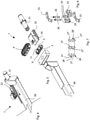
- a device 1 according to the invention is shown that is suitable for being fitted to a bending machine 3 of the type with three or four or more rollers to machine metal products, in particular to bend metal sheets 2.
- the device 1 guides and directs a metal sheet 2, in particular a metal sheet 2 having curved longitudinal edges, in the bending machine 3 to obtain, by a continuous bending process, a conical structure, for example in particular a frustoconical structure intended to be used in the wind-power sector.
- the device 1 can be fitted to a plane P for advancing and resting the metal sheet 2, for example a plane P of the roller conveyor type or to another support placed upstream of the curvature rollers 34, 35 of the bending machine 3.
- the device 1, or several devices 1 can be fitted in several different positions, upstream and or downstream, of the aforesaid rollers 34 and/or 34, or also in a position aligned on the rollers 34, i.e. on the plane that is coplanar with the axes of these rollers, near a head zone of the rollers 34.
- the device 1, shown better in figures 4 to 12 comprises resting and contrasting means (4; 104; 204) extending along a closed path, and suitable for restingly receiving a longitudinal edge E of the metal sheet 2 and contrasting a movement of the edge E transversely to the correct advancement trajectory T along which the metal sheet 2 is supplied to and through the bending machine 3. More precisely, the resting and contrasting means (4; 104; 204) is particularly suitable for coming into contact with a shorter curved longitudinal edge E of the metal sheet 2, i.e. the substantially longitudinal edge with a concave curvature that is more internal than the advancement trajectory T along which the metal sheet 2 moves.
- the advancement trajectory T in the case of a continuous conical curvature operation, is a curved trajectory.
- the device 1 comprises a supporting body S for the aforesaid resting and contrasting means (4; 104; 204), having at least one oblong lateral portion 5 that is suitable for facing the aforesaid edge E.
- the oblong lateral portion 5 is configured for conforming, i.e. imposing an extent that is longitudinal to the resting and contrasting means (4; 104; 204) such as to match as much as possible with the extent, i.e. longitudinal profile of the edge E.
- the edge E of the metal sheet 2 to be guided in the case of a conical curvature process, has a curved extent (i.e. it is a circumference sector), and for this reason the supporting body S that acts as a guide for the resting and contrasting means (4; 104; 204), can have a slightly convex geometry to impose on the resting and contrasting means (4; 104; 204) a geometry that reproduces as far as possible the curved extent of the edge E, and enables it to become coupled as far as possible with the curved profile of the metal sheet 2.
- the side portion 5 has a convex profile so as to force the resting and contrasting means (4; 104; 204) to conform to the concave edge E.
- the resting and contrasting means (4; 104; 204) extends around the supporting body S along a closed loop path, which can be oblong, triangular or rectangular in shape or be of another suitable shape provided that it has at least one longer side that is intended for a more extensive contact with the edge E of the metal sheet.
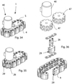
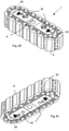
- the resting and contrasting means (4; 104; 204) comprises a plurality of track link elements 4 that are connected together by an articulated connection.
- Each track link element 4 comprises, externally, a contact surface 7 that is suitable for interacting, i.e. coming into contact with the edge E of the metal sheet 2 to be bent.
- the contact surface 7 extends longitudinally with a flat or slightly convex shape to adapt to the geometry of the curved edge E of the metal sheet 2.
- each track link element 4 is provided behind, i.e. on the side intended to face the supporting body S, with longitudinal mutually parallel rib portions 24 that together define extended longitudinal recesses 29.
- Connecting pins 26 are provided that extend transversely through said rib portions (24) and by which, inside the longitudinal recesses 29, one or more wheels 25, partially protruding outside the recesses, 29 are rotatably fitted, arranged for being able to roll on respective tracks 6 obtained peripherally on the supporting body S, thus enabling a fluid movement of the track link elements 4 along the entire perimeter of the supporting body S.
- the track link elements 4 are mutually articulated by chain link elements 23 that are connected by the aforesaid connecting pins 26.
- the track link elements 4 are mutually articulated directly, i.e. devoid of mesh elements 23.
- each track link element 4 comprises, at a first end, first wing portions 27 alternating with one or more concatenation seats 28, and, at a second end, second wing portions 27' that alternate with one or more respective concatenation seats 28'.
- the first wing portions 27 and concatenation seats 28 are geometrically formed to couple, by suitable connecting pins, respectively with the second wing portions 27' and the concatenation seats 28' of another track link element 4 placed in an adjacent position, and so on.
- each track link element 4 can have several desired geometrical shapes, in function of the particular geometry of the edge E of the metal sheet 2, in particular if the edge E is caulked and can have different possible transverse caulking profiles that are useful for subsequent welding.
- Figures 14 and 15 show the embodiment according to which the contact surface 7 has a profile, according to a cross section, which is flat, to establish a "facial" contact with the edge E, which is suitable for metal sheets without a caulked edge that would adhere to the entire height of the edge and for metal sheets with a caulked edge that anyway has a vertical part 7C.
- Figures 16 and 17 show another embodiment according to which the contact surface 7 comprises two surface zones 7A, 7B that are tilted and mutually convergent towards a longitudinal centre region but are connected together by a further surface strip (7C) having a linear transverse profile.
- the track link element 4 thus has a broken transverse profile that combines perfectly with the profile, formed in a complementary manner therewith, of the edge E of a metal sheet 2.
- Figures 18 and 19 show another embodiment according to which the contact surface 7 comprises two surface zones 7A, 7B that are tilted and reciprocally convergent and incident on a longitudinal centre region so as to define, on the track link element 4, a V-shaped recess that is suitable for receiving, and mating with, a caulked edge E' that terminates in a substantially sharp corner, that is thus geometrically different from the previously disclosed case.
- the resting and contrasting means comprises a web element 104, shaped for winding, and moving, around the aforesaid supporting body (S).
- the web element 104 is made of a flexible material, for example metal or anyway a material that has suitable resistance, hardness, or flexibility values, in general the mechanical and physical properties that are suitable for the function for which it is proposed.
- the web element 104 performs the same function as the track link elements 4, but provides a contact surface for the metal sheet 2 that is even greater and of continuous type.
- the resting and contrasting means comprises a belt element 204, shaped for winding, and moving, around the aforesaid supporting body S, wherein the belt element 204 comprises a substrate 204A in flexible material to which plates 204B are fixed that are suitable for coming into contact with said edge E of metal sheet 2.
- the substrate 204A made of flexible material is made of rubber, flexible plastics, metal or another material that is provided with suitable mechanical and physical features.
- the plates 204B can be made of metal or anyway of another material that is provided with the necessary mechanical and physical features that make the material suitable for supporting high contact pressures and mechanical stress in general.
- the resting and contrasting means (4; 104; 204) is thus movable around the supporting body S along a closed path so as to accompany the edge E of the metal sheet 2 by reciprocal distributed contact that is devoid of both relative sliding and of relative rolling.
- the device 1 according to the invention shows the advantage of avoiding relative sliding, thus sliding friction, with the edge of the advancing metal sheet 2.
- the device 1 ensures an extended area of contact with the edge E without rolling, thus rolling friction, being generated, thus succeeding in accompanying fluidly and precisely the metal sheet 2 along the correct advancement trajectory T to and through the bending machine 3, without compromising and damaging in any manner the edge E of the metal sheet 2.
- the device 1 is able to operate with a wide range of metal sheet geometries.
- the latter can couple effectively with curvature radii of the smallest inner edge (the concave edge E) that vary from about 8-10 metres upwards until they reach a rectangular geometry of the metal sheet, which generates a structure that is no longer conical but cylindrical.
- curvature radii of the smallest inner edge the concave edge E
- this inner radius of curvature grows, the degree of curvature of the trajectory is reduced correspondingly that the metal sheet has to follow to be bent, and thus the metal sheet has ever less need to rotate during movement.
- the supporting body, or supporting head S can, in a non-limiting manner, have a variable geometry, as explained below.
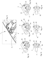
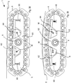
- the supporting head S can advantageously consist of several parts (12, 13, 14, 15, 16; 17, 18, 19) that are mutually connected, the reciprocal position of which is variable by suitable adjusting means (20, 21, 22), or by elastic connecting means, so as to be able to modify the geometric shape of the supporting head S to adapt the shape of the closed path of the resting and contrasting means (4; 104; 204), such as the track link elements, or web or belt, to the longitudinal geometric profile of the edge E of the metal sheet 2.
- the aforesaid adjusting means can comprise screw means 20, and/or thickening means 21, and/or means 22 of the wedge type and/or of the threaded cones type, or of other similar or equivalent types provided that they are able to space apart from one another in a desired manner the parts (12, 13, 14, 15, 16; 17, 18, 19) that make up the supporting head S.
- the elastic connecting means can comprise rubber articulated joints or metal spring elements or other equivalent means.
- the supporting body S consists of a base part 12 and two end parts 13 and 14, the position of which with respect to the base part 12 can be adjusted by acting on suitable adjusting means, such as screws 20, thickening means 21 or other connecting and adjusting devices.
- the supporting body S is divided into several portions, for example a central part 17, and two parts 18, 19 placed at opposite ends.
- the parts 17, 18, 19 are connected together by the aforesaid elastic connecting means, which gives the supporting body S an "elastic configuration". Owing to the corresponding variable positioning between the central part 17, and the parts 18, 19, the geometric configuration is modifiable of the closed path along which the resting and contrasting means (4; 104; 204) extends.
- the elastic connecting means enables the parts 17, 18, 19 to be arranged reciprocally, adapting to the curvature of said edge E.
- the objective is achieved of having track link elements 4 (or similarly the web 104 or belt 204) resting, with an extended contact, on the curved inner edge E, of the metal sheet 2, forcing the metal sheet 2, by the distributed pressing action, to rotate slightly to ensure the correct geometry of the cone, i.e. maintaining the generators thereof parallel to the axis of the rollers 34 of the bending machine 3.
- This embodiment of a supporting body S with an "elastic geometry” thus permits “automatic” adaptation of the curvature of the portion thereof intended to interact directly with the edge E of the metal sheet 2.
- variable convexity of the supporting body S enables the track link elements 4 or a web 104, or a belt 204, to be coupled perfectly with a curved circumference portion of the edge E with which they come into contact.
- FIG. 38 to 44 another embodiment of device 1 is shown with a supporting body S with variable geometry, in particular self-aligning geometry.
- the supporting body S is defined by two self-aligning parts 62, 64 of oscillating type, i.e. configured for rotating, under the action of the pressure that they receive from the edge E of the metal sheet 2, around a respective rotation axis W, with respect to the body 63 portion.
- Each self-aligning part comprises a rocker element 62, 64 hinged on a respective oscillation axis W placed nearer a central part of the supporting body S.
- Elastic contrasting elements 65 is provided that lies on a zone of the respective rocker element 62, 64 placed further away from the central zone of the supporting body S.
- the elastic contrasting elements 65 acts to move the rocker elements 62, 64 to the edge E of the metal sheet.
- the elastic contrasting elements 65 in particular comprises compression springs, or other equivalent elastic means.
- the rocker elements 62, 64 In interaction with the metal sheet 2, the rocker elements 62, 64, through the effect of the pressure that they receive from the edge E of the metal sheet 2, oscillate so as to adapt the longitudinal profile of the path - along which the resting and contrasting means (4; 104; 204) advances - to the curvature of the edge E of metal sheet 2.
- a greater curvature (lesser curvature radius) of the edge E will be matched by a greater rotation of the rocker elements 62, 64 and vice versa.
- the supporting body S comprises parts 71 that are movable transversely to the longitudinal extent of the supporting body S
- the adjusting means comprises hydraulic contrasting elements 72 arranged for acting on the aforesaid parts 71 to adapt the position and path of the resting and contrasting means (4; 104; 204) to the curvature of the longitudinal edge E.
- the device 1 that is thus configured turns out to be even more effective in the action of guiding the metal sheets 2, adapting perfectly to the degree of curvature of the longitudinal edges.
- the occurrence of undesired localized pressure forces is effectively prevented, ensuring on the other hand more even and extensive distribution along the mutual contact surface between the device 1 and the edge E of the metal sheet 2.
- the resting and contrasting means (4; 104; 204) is supported in a freely rotatable manner by the supporting body S, i.e. the movement of the resting and contrasting means (4; 104; 204) is determined by the contact with the edge E of the advancing metal sheet 2.
- the extended contact and the pressure exchanged in a distributed and uniform manner between the resting and contrasting means (4; 104; 204) and the edge E means that the resting and contrasting means (4; 104; 204) is dragged by the metal sheet 2 itself, without however phenomena of relative sliding being generated therebetween.
- the metal sheet clamped between the rollers 34 is dragged forwards by rotation thereof.
- the track link elements 4 thus perform effectively the function of "accompanying” and “contrasting” (transversely to the trajectory) the edge E of the metal sheet 2 to rotate the metal sheet 2 slightly, ensuring the correct conical geometry to be obtained.
- a driven embodiment of the device 1 is also provided.
- the resting and contrasting means (4; 104; 204) is driven to move actively at a speed correlated with the speed of the edge (E) with which they are in contact, by an electromechanical transmission or a transmission of hydraulic type.
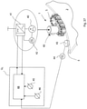
- a driven embodiment of the device 1 in which the resting and contrasting means (4; 104; 204) is driven by motor-means 40 fitted to the supporting body S.
- the driven embodiment is shown only with reference to the form of implementation with track link elements 4, without naturally excluding that the driven embodiment is identically applicable to cases in which the web element 104 or the belt element 204 are provided.
- toothed wheels 47 are provided on which the track link elements 4 are wound.
- the teeth of the toothed wheels 47 take a direct hold of the connecting pins 26 to which, in this case, the wheels 25 of the embodiments previously disclosed are not connected.
- the motor-means 40 is of the variable rotational speed type, in order to be able to adapt to the advancement speed of the edge E of the metal sheet 2 to be accompanied.
- Sensor means 42 is provided that detects the current speed of the motor-means 40, and thus the resting and contrasting means (4; 104; 204).
- the motor-means 40 is of the type comprising electric inverter means 41 or of the hydraulic drive type, comprising a variable hydraulic flowrate drive device.
- the device 1 includes further sensor means (43, 44), configured for detecting the instantaneous speed of the edge E near the resting and contrasting means (4; 104; 204).
- This sensor means can comprise a measuring wheel 43, or other device with the same function, intended to make contact with the edge E to be rotated by the latter and be operationally coupled with an electronic detector 44, for example of the encoder type.
- a control unit Uc is provided that is configured for receiving and comparing incoming signals generated by the sensor means 42 and by the further sensor means 43, 44 and consequently commanding the drive speed of the motor-means 40 to synchronize the current speed of the resting and contrasting means (4; 104; 204) with the current speed of the edge E of the metal sheet 2.
- the control unit U C comprises a programmable logic controller (PLC) 48 having a microprocessor that is suitably programmed for executing, on the basis of the signals of the sensor means 42 and 43, an automatic correction of the speed of the motor-means 40 to synchronize the track link elements 4 (or web element 104, or belt element 204) with the current speed of the edge E, preventing relative sliding phenomena.
- PLC programmable logic controller
- Suitable components 45 and 46 enable the kinematics of the metric measuring wheel 45 and of the track link elements 4 (or web element 104, or belt element 204) to be correctly calibrated or adjusted.
- the device 1 comprises a guiding crossbar 30, shown better in Figures 2 to 5 , on which the support body S is supported for the resting and contrasting elements (4; 104; 204).
- the guiding crossbar 30 is suitable for being fitted to the advancement and resting plane P of the bending machine 3.
- the supporting body S is connected to actuating means 31 owing to which it is movable along guiding crossbar 30, in a direction that is transverse to the advancement trajectory T of the metal sheet 2.
- the supporting body or head S has a hole 11 for connecting - by a pin 10 - to a slide 32 that is movable on the guiding crossbar 30.
- the connection between the pin 10 and the hole 11 confers on the supporting body S a certain degree of rotational freedom around an axis of vertical oscillation X, so as to be able to adapt to the lie of the edge E of the metal sheet 2.
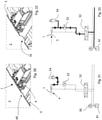
- the actuating means 31 comprises a dual-effect hydraulic cylinder 31, supplied by a pump 50 from a circuit 51 along which a four-way distributor 52 is provided (e.g. of the solenoid valve or slide valve type), having three possible different operating positions, and a valve 53 for example of overcentre or equivalent type.
- a four-way distributor 52 e.g. of the solenoid valve or slide valve type
- An accumulator device 54 such as a container that is arranged for receiving incoming oil coming from the hydraulic cylinder 31, can be connected to the rear chamber of the hydraulic cylinder 31, i.e. the chamber that is filled to project the piston externally and send the support head S to abut against the edge E of the metal sheet.
- the accumulator device 54 is arranged to act as a plenum to absorb and dampen possible overloads imposed on said resting and contrasting means (4; 104; 204) that are caused by irregularities (60) on the edge E of the metal sheet 2.
- the overcentre valve (53) and the four-way distributor 52 are configured for cooperating, in a "safety" operating mode, to enable oil to be transferred from the rear chamber of the hydraulic cylinder 31 to a tank 61 of the circuit, if the resting and contrasting means (4; 104; 204) intercepts an undesired anomalous protrusion 70 of the edge E, that is potentially harmful for the structural integrity of the device 1 or of other structural parts.
- the dose of oil temporarily received in the accumulator device 54 is returned to the rear chamber of the hydraulic cylinder 31, returning the head S to the correct work position in contact with the edge E.
- An anomalous shape of the curved edge E could be excessive with respect to the "absorption" capacity of the accumulator device 54, not being able in this manner to dampen sufficiently the load generated on the head S.
- the valve 53 intervenes that enables the transfer of oil from the rear chamber of the cylinder 31 to the tank 61, throttling the passage thereof in a controlled manner. In this manner, the head S with the track link elements 4 is enabled to be pushed backwards by the pressure exerted by the protrusion 70 of the metal sheet, preventing undesired damage due to an overload.
Landscapes
- Engineering & Computer Science (AREA)
- Mechanical Engineering (AREA)
- General Engineering & Computer Science (AREA)
- Bending Of Plates, Rods, And Pipes (AREA)
Claims (27)
- Vorrichtung zum Führen und Lenken eines Blechs (2) in einer Biegemaschine (3), um kontinuierlich eine kegelförmige Struktur, insbesondere eine kegelstumpfförmige Struktur zu bilden, wobei die Vorrichtung (1) umfasst:- Auflage- und Kontrastiermittel (4; 104; 204), das sich entlang eines geschlossenen Pfads erstreckt und geeignet ist, eine Längskante (E) des Blechs (2) in Auflage aufzunehmen und eine Bewegung der Kante (E) in einer Richtung, die quer zu einer voreingestellten Vorschubbahn (T) des Blechs (2) verläuft, zu kontrastieren,- einen Trägerkörper (S) für das Auflage- und Kontrastiermittel (4; 104; 204), der mindestens einen länglichen lateralen Abschnitt (5) aufweist, der geeignet ist, der Kante (E) zugewandt zu sein, und der eingerichtet ist, das Auflage- und Kontrastiermittel (4; 104; 204) an das Längsprofil der Kante (E) anzupassen, um so eine erweiterte Kontaktzone mit der Kante (E) zu erhalten und kontrastierenden Druck aufzubringen, der entlang der Kante (E) verteilt ist,- wobei das Auflage- und Kontrastiermittel (4; 104; 204) um den Trägerkörper (S) entlang des geschlossenen Pfads beweglich ist, um die Kante (E) des Blechs durch einen verteilten Kontakt ohne relatives Gleiten und Rollen zu begleiten, um das Blech (2) in Bewegung entlang der voreingestellten Vorschubbahn (T) zu der und durch die Biegemaschine (3) zu versetzen,
wobei die Vorrichtung DADURCH GEKENNZEICHNET IST, dass der Trägerkörper (S) aus mehreren gegenseitig verbundenen Teilen (12, 13, 14, 15, 16; 17, 18, 19; 62, 63, 64; 71) besteht, wobei die gegenseitige Position der Teile durch Einstellmittel (20, 21, 22; 65; 72) variabel ist, um so die geometrische Form des Trägerkörpers (S) zu verändern, um die Form des geschlossenen Pfads des Auflage- und Kontrastiermittels (4; 104; 204) an das geometrische Längsprofil der Kante (E) des Blechs (2) anzupassen. - Vorrichtung nach Anspruch 1, wobei der Trägerkörper durch einen Stützkopf (S) definiert ist, um den herum Führungsbahnen (6) seitlich für das Auflage- und Kontrastiermittel (4; 104; 204) erhalten werden.
- Vorrichtung nach Anspruch 1 oder 2, wobei der längliche laterale Abschnitt (5) des Trägerkörpers (S) ein konvexes Längsprofil aufweist, um dem Auflage- und Kontrastiermittel (4; 104; 204) eine Krümmung zu verleihen, die zu dem konkaven Längsprofil der Kante (E) von Blech (2) passt.
- Vorrichtung nach einem vorstehenden Anspruch, wobei das Einstellmittel (20, 21, 22) zum Variieren der gegenseitigen Position der Teile (12, 13, 14, 15, 16) dient, wobei das Einstellmittel Schraubmittel (20) und/oder Verdickungsmittel (21) und/oder Mittel (22) des Keiltyps und/oder vom Gewindekegeltyp umfasst, wobei das Einstellmittel eingerichtet ist, die Teile (12, 13, 14, 15, 16; 17, 18, 19) des Trägerkörpers (S) auf gewünschte Weise voneinander zu beabstanden.
- Vorrichtung nach einem der Ansprüche 1 bis 3, wobei die Teile (17, 18, 19) durch elastische Mittel miteinander verbunden sind, wobei die elastischen Verbindungsmittel den Teilen (17, 18, 19), in Kontaktposition mit und Druck ausübend auf die Kante (E), ermöglichen, in Anpassung an die Krümmung der Kante (E) gegenseitig angeordnet zu sein.
- Vorrichtung nach einem der Ansprüche 1 bis 3, wobei der Trägerkörper (S) durch zwei selbstausrichtende Teile (62, 64) definiert ist, die eingerichtet sind, um jeweilige Drehachsen (W) durch die Wirkung des Drucks zu drehen, der durch das Blech (2) ausgeübt wird, um so das Längsprofil des Trägerkörpers (S) und somit den Pfad des Auflage- und Kontrastiermittels (4; 104; 204) an die Krümmung des Längsprofils der Kante (E) von Blech anzupassen.
- Vorrichtung nach Anspruch 6, wobei jeder der zwei selbstausrichtenden Teile ein Schwenkelement (62, 64) umfasst, das an eine jeweilige Schwingungsachse (W) angelenkt ist, die näher bei einem mittleren Teil des Trägerkörpers (S) platziert ist, und das Einstellmittel elastische Kontrastierelemente (65) umfasst, die auf jedem Schwenkelement (62, 64) auf einer Zone des letztgenannten liegen, die näher zu einem jeweiligen Ende des Trägerkörpers (S) ist.
- Vorrichtung nach einem der Ansprüche 1 bis 3, in der der Trägerkörper (S) Teile (71) umfasst, die quer zu dem Längsverlauf des Trägerkörpers (S) beweglich sind, wobei das Einstellmittel hydraulische Kontrastierelemente (72) umfasst, die angeordnet sind, auf die Teile (71) zu wirken, um die Position und den Pfad des Auflage- und Kontrastiermittels (4; 104; 204) an die Krümmung der Längskante (E) anzupassen.
- Vorrichtung nach einem vorstehenden Anspruch, wobei das Auflage- und Kontrastiermittel eine Vielzahl von Bahnverbindungselementen (4) umfasst, die durch eine gelenkige Verbindung miteinander verbunden sind.
- Vorrichtung nach Anspruch 9, wobei jedes Bahnverbindungselement (4) eine Kontaktoberfläche (7) umfasst, die zur Interaktion mit der Kante (E) geeignet ist, wobei sich die Kontaktoberfläche (7) in Längsrichtung mit einer flachen oder leicht konvexen Form erstreckt, um sich an die gekrümmte Kante (E) des Blechs (2) anzupassen.
- Vorrichtung nach Anspruch 10, wobei jede Kontaktoberfläche (7) ein Profil gemäß einem Querschnitt aufweist, das so geformt ist, dass es sich an ein Verstemmprofil der Kante (E) des Blechs (2) anpasst.
- Vorrichtung nach Anspruch 10 oder 11, wobei jede Kontaktoberfläche (7) zwei Oberflächenzonen (7A, 7B) umfasst, die geneigt sind und gegenseitig auf einer Mittellinienregion in Längsrichtung konvergieren, um auf dem jeweiligen Bahnverbindungselement (4) eine V-förmige Aussparung zu definieren, die zum Aufnehmen und Abstimmen der verstemmten Kante (E) des Blechs (2) geeignet ist.
- Vorrichtung nach Anspruch 12, wobei die zwei Oberflächenzonen (7A, 7B) durch einen weiteren Oberflächenstreifen (7C), der ein lineares Querprofil aufweist, verbunden sind.
- Vorrichtung nach einem der Ansprüche 9 bis 13, wobei jedes Bahnverbindungselement (4) wechselseitig parallele Längsrippenabschnitte (24) umfasst, um gemeinsam Längsaussparungen (29) zu definieren, wobei weiter Verbindungsstifte (26) bereitgestellt sind, die sich quer durch die Rippenabschnitte (24) erstrecken.
- Vorrichtung nach Anspruch 14, wobei die Längsaussparungen (29) Räder (25) aufnehmen, die geformt sind, auf jeweiligen Bahnen (6) zu rollen, die auf dem Trägerkörper (S) erhalten werden, wobei die Räder (25) drehbar an den Verbindungsstiften (26) sitzen.
- Vorrichtung nach Anspruch 14 oder 15, wobei die Bahnverbindungen der Bahnverbindungselemente (4) wechselseitig durch Kettenverbindungselemente (23) angelenkt sind, die durch die Verbindungsstifte (26) verbunden sind.
- Vorrichtung nach einem der Ansprüche 9 bis 15, wobei jedes Bahnverbindungselement (4) an einem ersten Ende erste Flügelabschnitte (27) und einen oder mehrere Verkettungssitze (28) und an einem zweiten Ende zweite Flügelabschnitte (27') und einen oder mehrere jeweilige Verkettungssitze (28') umfasst, wobei die ersten Flügelabschnitte (27) und Verkettungssitze (28) ausgebildet sind, jeweils mit den zweiten Flügelabschnitten (27') und den Verkettungssitzen (28') eines benachbarten Bahnverbindungselements (4) zu koppeln.
- Vorrichtung nach einem der Ansprüche 1 bis 8, wobei das Auflage- und Kontrastiermittel ein Stegelement (104) umfasst, das aus einem flexiblen Metallmaterial oder einem anderen Material ausreichenden Widerstands hergestellt ist, das angepasst ist, sich um den Trägerkörper (S) zu wickeln und zu bewegen.
- Vorrichtung nach einem der Ansprüche 1 bis 8, wobei das Auflage- und Kontrastiermittel ein Riemenelement (204) umfasst, das angepasst ist, sich um den Trägerkörper (S) zu wickeln und zu bewegen, wobei das Riemenelement (204) ein Substrat (204A) umfasst, das aus einem flexiblen Material hergestellt ist, an dem Platten (204B) befestigt sind, die geeignet sind, mit der Kante (E) von Blech (2) in Kontakt zu gelangen.
- Vorrichtung nach einem vorstehenden Anspruch, wobei das Auflage- und Kontrastiermittel (4; 104; 204) angetrieben wird, sich aktiv bei einer Geschwindigkeit zu bewegen, die mit der Geschwindigkeit der Kante (E) korreliert, mit der das Auflage- und Kontrastiermittel (4; 104; 204) in Kontakt ist.
- Vorrichtung nach einem vorstehenden Anspruch, wobei das Auflage- und Kontrastiermittel (4; 104; 204) von einem Motormittel (40) angetrieben wird, das an dem Trägerkörper (S) sitzt, wobei das Motormittel (40) mit einem Sensormittel (42) gekoppelt ist, um die aktuelle Geschwindigkeit des Motormittels (40) und somit des Auflage- und Kontrastiermittels (4; 104; 204) zu erfassen.
- Vorrichtung nach Anspruch 21, wobei das Motormittel (40) von der Art, die elektrische Umrichtermittel (41) umfasst, oder der hydraulischen Antriebsart ist, die eine variable hydraulische Strömungsratenantriebsvorrichtung umfasst.
- Vorrichtung nach Anspruch 21 oder 22, die weiter ein Sensormittel (43, 44) umfasst, das zum Erfassen der momentanen Geschwindigkeit der Kante (E) nahe dem Auflage- und Kontrastiermittel (4; 104; 204) eingerichtet ist, wobei weiter eine Steuereinheit (Uc) bereitgestellt ist, die zum Empfangen und Vergleichen der eingehenden Signale eingerichtet ist, die von dem Sensormittel (42) und dem weiteren Sensormittel (43, 44) generiert werden und anschließend die Antriebsgeschwindigkeit des Motormittels (40) bestimmen, um die aktuelle Geschwindigkeit des Auflage- und Kontrastiermittels (4; 104; 204) mit der aktuellen Geschwindigkeit der Kante (E) von Blech (2) zu synchronisieren.
- Vorrichtung nach einem vorstehenden Anspruch, wobei der Trägerkörper (S) an einer Führungsquerstange (30) sitzt, die geeignet ist, an einer Ebene (P) zum Vorschieben und Auflegen des Blechs (2) zu sitzen, und wobei der Trägerkörper (S) mit einem Betätigungsmittel (31) verbunden ist, durch das der Trägerkörper (S) entlang der Führungsquerstange (30) bewegbar ist.
- Vorrichtung nach Anspruch 24, wobei der Trägerkörper (S) durch Stiftmittel (10) mit der Führungsquerstange (30) verbunden ist, wobei der Trägerkörper (S) einen bestimmten Grad an Rotationsfreiheit um eine Schwingungsachse (X) aufweist, um imstande zu sein, sich an eine Krümmung der Kante (E) des Blechs (2) anzupassen.
- Vorrichtung nach Anspruch 24 oder 25, wobei das Betätigungsmittel (31) einen hydraulischen Doppeleffektzylinder (31) umfasst, der von einer Pumpe (50) durch einen Kreislauf (51) versorgt wird, entlang dem ein Vierwegeverteiler (52) mit drei möglichen unterschiedlichen Betriebspositionen und ein Lasthalteventil (53) bereitgestellt sind, mit der hinteren Kammer des hydraulischen Zylinders (31) eine Sammelvorrichtung (54) verbunden ist, die angeordnet ist, eingehendes Öl, das von dem hydraulischen Zylinder (31) kommt, aufzunehmen, die als eine Plenumkammer dient, um mögliche Überlasten, die auf das Auflage- und Kontrastiermittel (4; 104; 204) wirken und durch Unregelmäßigkeiten (60) der Kante (E) von Blech (2) verursacht werden, zu absorbieren und zu dämpfen, wobei das Lasthalteventil (53) und der Vierwegeverteiler(52) eingerichtet sind, gemäß einem Sicherheitsmodus zusammenzuarbeiten, um zu ermöglichen, dass Öl von der hinteren Kammer des hydraulischen Zylinders (31) zu einem Tank (61) überführt wird, wenn das Auflage- und Kontrastiermittel (4; 104; 204) einen unerwünschten anomalen Vorsprung (70) der Kante (E) auffängt, der möglicherweise für die strukturelle Integrität der Vorrichtung (1) schädlich ist.
- Verfahren zum Führen und Lenken eines Blechs (2) in einer Biegemaschine (3), um kontinuierlich eine kegelförmige Struktur, insbesondere eine kegelstumpfförmige Struktur zu bilden, umfassend die folgenden Schritte:- In-Kontakt-Bringen einer Längskante (E) des Blechs (2) mit einem Auflage- und Kontrastiermittel (4; 104; 204), das sich entlang einer geschlossenen Pfads erstreckt,- Kontrastieren, durch die Auflage- und Kontrastiermittel (4; 104; 204), einer Bewegung der Kante (E) in einer Richtung, die quer zu einer voreingestellten Vorschubbahn (T) des Blechs (2) verläuft,- Anpassen des Auflage- und Kontrastiermittels (4; 104; 204) an das Längsprofil der Kante (E), um so eine erweiterte Kontaktzone mit der Kante (E) zu erhalten, entlang der ein kontrastierender verteilter Druck auf die Kante (E) ausgeübt wird,- Bewegen der Auflage- und Kontrastiermittel (4; 104; 204), entlang des geschlossenen Pfads um einen Trägerkörper (S), der mindestens einen länglichen lateralen Abschnitt (5) aufweist, der der Kante (E) zugewandt ist, bei einer Geschwindigkeit, die jener der Kante (E) von Blech (2) entspricht, ohne relatives Gleiten und Rollen, und- Begleiten der Kante (E) von Blech (2), um das Blech (2) in Bewegung entlang der voreingestellten Vorschubbahn (T) zu der und durch die Biegemaschine (3) zu versetzen.
Applications Claiming Priority (2)
| Application Number | Priority Date | Filing Date | Title |
|---|---|---|---|
| IT102017000067523A IT201700067523A1 (it) | 2017-06-16 | 2017-06-16 | Dispositivo e metodo per guidare e direzionare una lamiera in una calandra curvatrice per l'ottenimento di strutture troncoconiche |
| PCT/IB2018/054412 WO2018229719A1 (en) | 2017-06-16 | 2018-06-15 | Device and method for guiding and directing a metal sheet in a bending machine to obtain frustoconical structures |
Publications (2)
| Publication Number | Publication Date |
|---|---|
| EP3638432A1 EP3638432A1 (de) | 2020-04-22 |
| EP3638432B1 true EP3638432B1 (de) | 2022-03-09 |
Family
ID=60182923
Family Applications (1)
| Application Number | Title | Priority Date | Filing Date |
|---|---|---|---|
| EP18737723.9A Active EP3638432B1 (de) | 2017-06-16 | 2018-06-15 | Vorrichtung und verfahren zum führen und ausrichten eines blechs in einer biegemaschine zum erhalt von kegelstumpfförmigen strukturen |
Country Status (7)
| Country | Link |
|---|---|
| US (1) | US11135639B2 (de) |
| EP (1) | EP3638432B1 (de) |
| DK (1) | DK3638432T3 (de) |
| ES (1) | ES2913749T3 (de) |
| IT (1) | IT201700067523A1 (de) |
| PT (1) | PT3638432T (de) |
| WO (1) | WO2018229719A1 (de) |
Cited By (1)
| Publication number | Priority date | Publication date | Assignee | Title |
|---|---|---|---|---|
| IT202300014766A1 (it) | 2023-07-14 | 2025-01-14 | Promau Srl | Dispositivo e metodo per guidare e direzionare una lamiera in una calandra |
Families Citing this family (2)
| Publication number | Priority date | Publication date | Assignee | Title |
|---|---|---|---|---|
| EP3903924A4 (de) | 2018-12-26 | 2022-06-22 | M. Technique Co., Ltd. | Fluidbehandlungsvorrichtung |
| DE102023109827A1 (de) * | 2023-04-19 | 2024-10-24 | Haeusler Holding Ag | Konusförmiges Biegen eines Blechs |
Family Cites Families (8)
| Publication number | Priority date | Publication date | Assignee | Title |
|---|---|---|---|---|
| US2723886A (en) * | 1953-06-10 | 1955-11-15 | Market Forge Company | Antifriction device |
| US2808096A (en) * | 1954-01-11 | 1957-10-01 | Erkes William James | Guide device for causing a roller bending machine to form a cone |
| US2857158A (en) * | 1955-04-19 | 1958-10-21 | Ungerer Fritz | Guiding means for moving sheet-metal bands |
| DE1269084B (de) * | 1962-11-19 | 1968-05-30 | Boldrini S P A Fa | Vorrichtung zum Biegen von Blech, insbesondere zum Herstellen konischer Werkstuecke |
| US3398871A (en) * | 1966-04-01 | 1968-08-27 | Ungerer Irma | Apparatus for guiding metal strip |
| CH494604A (de) | 1968-08-10 | 1970-08-15 | Haeusler Christian | Rundmaschine zur Herstellung eines Konus aus einem kreisringsegmentförmigen Blech |
| JP3834704B2 (ja) | 1996-09-03 | 2006-10-18 | 株式会社大同機械製作所 | 金属板の円錐曲げ加工方法および装置 |
| CN103624166B (zh) | 2013-11-27 | 2017-01-04 | 中车长江车辆有限公司 | 一种导向装置、锥筒滚圆机及锥筒卷制方法 |
-
2017
- 2017-06-16 IT IT102017000067523A patent/IT201700067523A1/it unknown
-
2018
- 2018-06-15 WO PCT/IB2018/054412 patent/WO2018229719A1/en not_active Ceased
- 2018-06-15 PT PT187377239T patent/PT3638432T/pt unknown
- 2018-06-15 ES ES18737723T patent/ES2913749T3/es active Active
- 2018-06-15 US US16/621,963 patent/US11135639B2/en active Active
- 2018-06-15 DK DK18737723.9T patent/DK3638432T3/da active
- 2018-06-15 EP EP18737723.9A patent/EP3638432B1/de active Active
Cited By (2)
| Publication number | Priority date | Publication date | Assignee | Title |
|---|---|---|---|---|
| IT202300014766A1 (it) | 2023-07-14 | 2025-01-14 | Promau Srl | Dispositivo e metodo per guidare e direzionare una lamiera in una calandra |
| WO2025017433A1 (en) * | 2023-07-14 | 2025-01-23 | Promau S.R.L. | Device and method for guiding and directing a metal sheet in a curving calender |
Also Published As
| Publication number | Publication date |
|---|---|
| IT201700067523A1 (it) | 2018-12-16 |
| PT3638432T (pt) | 2022-05-06 |
| US20200130043A1 (en) | 2020-04-30 |
| US11135639B2 (en) | 2021-10-05 |
| WO2018229719A1 (en) | 2018-12-20 |
| DK3638432T3 (da) | 2022-05-30 |
| EP3638432A1 (de) | 2020-04-22 |
| ES2913749T3 (es) | 2022-06-06 |
Similar Documents
| Publication | Publication Date | Title |
|---|---|---|
| EP3638432B1 (de) | Vorrichtung und verfahren zum führen und ausrichten eines blechs in einer biegemaschine zum erhalt von kegelstumpfförmigen strukturen | |
| RU2551722C2 (ru) | Способ формования и формовочная машина | |
| EP3706930B1 (de) | Biegemaschine | |
| KR102369998B1 (ko) | 운송 시스템 | |
| RU2628591C2 (ru) | Устройство и способ для загиба кромок с использованием ролика | |
| WO2016019930A1 (en) | Bending head, especially for an automatic bending machine | |
| ES2865414T3 (es) | Conjunto de estirado y deformación | |
| ITBO20100083A1 (it) | Metodo e apparecchiatura per raddrizzare tondini di ferro e simili | |
| EP3700724B1 (de) | Vorrichtung zum herstellen von reifen sowie verfahren zum verbinden oder schneiden von reifenteilen | |
| EP2714295A1 (de) | Abkantpresse | |
| CN107000084A (zh) | 用于调节横切金属带材的滚筒式剪切机的刀片间隙的设备和方法 | |
| US8225636B2 (en) | Apparatus for forming a duct | |
| CA1317327C (en) | Apparatus for correctly feeding continuous strips with a shaped side outline to blanking machines | |
| EP3164262B1 (de) | Faltanordnung, faltmaschine mit dieser faltanordnung und verfahren zum falten mit dieser faltanordnung | |
| CN112607077B (zh) | 一种自动封盒机及封盒方法 | |
| US20160236254A1 (en) | Bending machine and method for bending a sheet metal workpiece | |
| KR101388040B1 (ko) | 벨트 컨베이어용 사행 방지장치 | |
| US10160027B2 (en) | Apparatus for closing pittsburgh seams associated with duct assemblies and other box-shaped members | |
| US4565084A (en) | Method and a tool for bending the edge of thick sheet metal | |
| JP6913618B2 (ja) | 矯正方法および矯正機 | |
| KR101503232B1 (ko) | 레이저 용접용 지그 장치 | |
| RU2828529C1 (ru) | Автоматический укладчик стальных холодногнутых профилей типа п и с | |
| KR20160009023A (ko) | 이동가능한 입구 쉴드를 갖는 롤러 배열체 | |
| KR101528155B1 (ko) | 용접강관 성형기의 프레스벤딩 기구 | |
| CN208928916U (zh) | 一种折弯角度可调折弯机 |
Legal Events
| Date | Code | Title | Description |
|---|---|---|---|
| STAA | Information on the status of an ep patent application or granted ep patent |
Free format text: STATUS: UNKNOWN |
|
| STAA | Information on the status of an ep patent application or granted ep patent |
Free format text: STATUS: THE INTERNATIONAL PUBLICATION HAS BEEN MADE |
|
| PUAI | Public reference made under article 153(3) epc to a published international application that has entered the european phase |
Free format text: ORIGINAL CODE: 0009012 |
|
| STAA | Information on the status of an ep patent application or granted ep patent |
Free format text: STATUS: REQUEST FOR EXAMINATION WAS MADE |
|
| 17P | Request for examination filed |
Effective date: 20200115 |
|
| AK | Designated contracting states |
Kind code of ref document: A1 Designated state(s): AL AT BE BG CH CY CZ DE DK EE ES FI FR GB GR HR HU IE IS IT LI LT LU LV MC MK MT NL NO PL PT RO RS SE SI SK SM TR |
|
| AX | Request for extension of the european patent |
Extension state: BA ME |
|
| DAV | Request for validation of the european patent (deleted) | ||
| DAX | Request for extension of the european patent (deleted) | ||
| STAA | Information on the status of an ep patent application or granted ep patent |
Free format text: STATUS: EXAMINATION IS IN PROGRESS |
|
| 17Q | First examination report despatched |
Effective date: 20210119 |
|
| GRAP | Despatch of communication of intention to grant a patent |
Free format text: ORIGINAL CODE: EPIDOSNIGR1 |
|
| STAA | Information on the status of an ep patent application or granted ep patent |
Free format text: STATUS: GRANT OF PATENT IS INTENDED |
|
| INTG | Intention to grant announced |
Effective date: 20210927 |
|
| GRAS | Grant fee paid |
Free format text: ORIGINAL CODE: EPIDOSNIGR3 |
|
| GRAA | (expected) grant |
Free format text: ORIGINAL CODE: 0009210 |
|
| STAA | Information on the status of an ep patent application or granted ep patent |
Free format text: STATUS: THE PATENT HAS BEEN GRANTED |
|
| AK | Designated contracting states |
Kind code of ref document: B1 Designated state(s): AL AT BE BG CH CY CZ DE DK EE ES FI FR GB GR HR HU IE IS IT LI LT LU LV MC MK MT NL NO PL PT RO RS SE SI SK SM TR |
|
| REG | Reference to a national code |
Ref country code: CH Ref legal event code: EP Ref country code: AT Ref legal event code: REF Ref document number: 1473692 Country of ref document: AT Kind code of ref document: T Effective date: 20220315 |
|
| REG | Reference to a national code |
Ref country code: IE Ref legal event code: FG4D |
|
| REG | Reference to a national code |
Ref country code: DE Ref legal event code: R096 Ref document number: 602018031989 Country of ref document: DE |
|
| REG | Reference to a national code |
Ref country code: NL Ref legal event code: FP |
|
| REG | Reference to a national code |
Ref country code: PT Ref legal event code: SC4A Ref document number: 3638432 Country of ref document: PT Date of ref document: 20220506 Kind code of ref document: T Free format text: AVAILABILITY OF NATIONAL TRANSLATION Effective date: 20220429 |
|
| REG | Reference to a national code |
Ref country code: DK Ref legal event code: T3 Effective date: 20220523 |
|
| REG | Reference to a national code |
Ref country code: ES Ref legal event code: FG2A Ref document number: 2913749 Country of ref document: ES Kind code of ref document: T3 Effective date: 20220606 |
|
| REG | Reference to a national code |
Ref country code: LT Ref legal event code: MG9D |
|
| PG25 | Lapsed in a contracting state [announced via postgrant information from national office to epo] |
Ref country code: SE Free format text: LAPSE BECAUSE OF FAILURE TO SUBMIT A TRANSLATION OF THE DESCRIPTION OR TO PAY THE FEE WITHIN THE PRESCRIBED TIME-LIMIT Effective date: 20220309 Ref country code: RS Free format text: LAPSE BECAUSE OF FAILURE TO SUBMIT A TRANSLATION OF THE DESCRIPTION OR TO PAY THE FEE WITHIN THE PRESCRIBED TIME-LIMIT Effective date: 20220309 Ref country code: NO Free format text: LAPSE BECAUSE OF FAILURE TO SUBMIT A TRANSLATION OF THE DESCRIPTION OR TO PAY THE FEE WITHIN THE PRESCRIBED TIME-LIMIT Effective date: 20220609 Ref country code: LT Free format text: LAPSE BECAUSE OF FAILURE TO SUBMIT A TRANSLATION OF THE DESCRIPTION OR TO PAY THE FEE WITHIN THE PRESCRIBED TIME-LIMIT Effective date: 20220309 Ref country code: HR Free format text: LAPSE BECAUSE OF FAILURE TO SUBMIT A TRANSLATION OF THE DESCRIPTION OR TO PAY THE FEE WITHIN THE PRESCRIBED TIME-LIMIT Effective date: 20220309 Ref country code: BG Free format text: LAPSE BECAUSE OF FAILURE TO SUBMIT A TRANSLATION OF THE DESCRIPTION OR TO PAY THE FEE WITHIN THE PRESCRIBED TIME-LIMIT Effective date: 20220609 |
|
| REG | Reference to a national code |
Ref country code: AT Ref legal event code: MK05 Ref document number: 1473692 Country of ref document: AT Kind code of ref document: T Effective date: 20220309 |
|
| PG25 | Lapsed in a contracting state [announced via postgrant information from national office to epo] |
Ref country code: LV Free format text: LAPSE BECAUSE OF FAILURE TO SUBMIT A TRANSLATION OF THE DESCRIPTION OR TO PAY THE FEE WITHIN THE PRESCRIBED TIME-LIMIT Effective date: 20220309 Ref country code: GR Free format text: LAPSE BECAUSE OF FAILURE TO SUBMIT A TRANSLATION OF THE DESCRIPTION OR TO PAY THE FEE WITHIN THE PRESCRIBED TIME-LIMIT Effective date: 20220610 Ref country code: FI Free format text: LAPSE BECAUSE OF FAILURE TO SUBMIT A TRANSLATION OF THE DESCRIPTION OR TO PAY THE FEE WITHIN THE PRESCRIBED TIME-LIMIT Effective date: 20220309 |
|
| PG25 | Lapsed in a contracting state [announced via postgrant information from national office to epo] |
Ref country code: SM Free format text: LAPSE BECAUSE OF FAILURE TO SUBMIT A TRANSLATION OF THE DESCRIPTION OR TO PAY THE FEE WITHIN THE PRESCRIBED TIME-LIMIT Effective date: 20220309 Ref country code: SK Free format text: LAPSE BECAUSE OF FAILURE TO SUBMIT A TRANSLATION OF THE DESCRIPTION OR TO PAY THE FEE WITHIN THE PRESCRIBED TIME-LIMIT Effective date: 20220309 Ref country code: RO Free format text: LAPSE BECAUSE OF FAILURE TO SUBMIT A TRANSLATION OF THE DESCRIPTION OR TO PAY THE FEE WITHIN THE PRESCRIBED TIME-LIMIT Effective date: 20220309 Ref country code: EE Free format text: LAPSE BECAUSE OF FAILURE TO SUBMIT A TRANSLATION OF THE DESCRIPTION OR TO PAY THE FEE WITHIN THE PRESCRIBED TIME-LIMIT Effective date: 20220309 Ref country code: CZ Free format text: LAPSE BECAUSE OF FAILURE TO SUBMIT A TRANSLATION OF THE DESCRIPTION OR TO PAY THE FEE WITHIN THE PRESCRIBED TIME-LIMIT Effective date: 20220309 Ref country code: AT Free format text: LAPSE BECAUSE OF FAILURE TO SUBMIT A TRANSLATION OF THE DESCRIPTION OR TO PAY THE FEE WITHIN THE PRESCRIBED TIME-LIMIT Effective date: 20220309 |
|
| PG25 | Lapsed in a contracting state [announced via postgrant information from national office to epo] |
Ref country code: PL Free format text: LAPSE BECAUSE OF FAILURE TO SUBMIT A TRANSLATION OF THE DESCRIPTION OR TO PAY THE FEE WITHIN THE PRESCRIBED TIME-LIMIT Effective date: 20220309 Ref country code: IS Free format text: LAPSE BECAUSE OF FAILURE TO SUBMIT A TRANSLATION OF THE DESCRIPTION OR TO PAY THE FEE WITHIN THE PRESCRIBED TIME-LIMIT Effective date: 20220709 Ref country code: AL Free format text: LAPSE BECAUSE OF FAILURE TO SUBMIT A TRANSLATION OF THE DESCRIPTION OR TO PAY THE FEE WITHIN THE PRESCRIBED TIME-LIMIT Effective date: 20220309 |
|
| REG | Reference to a national code |
Ref country code: DE Ref legal event code: R097 Ref document number: 602018031989 Country of ref document: DE |
|
| PLBE | No opposition filed within time limit |
Free format text: ORIGINAL CODE: 0009261 |
|
| STAA | Information on the status of an ep patent application or granted ep patent |
Free format text: STATUS: NO OPPOSITION FILED WITHIN TIME LIMIT |
|
| PG25 | Lapsed in a contracting state [announced via postgrant information from national office to epo] |
Ref country code: MC Free format text: LAPSE BECAUSE OF FAILURE TO SUBMIT A TRANSLATION OF THE DESCRIPTION OR TO PAY THE FEE WITHIN THE PRESCRIBED TIME-LIMIT Effective date: 20220309 |
|
| 26N | No opposition filed |
Effective date: 20221212 |
|
| PG25 | Lapsed in a contracting state [announced via postgrant information from national office to epo] |
Ref country code: SI Free format text: LAPSE BECAUSE OF FAILURE TO SUBMIT A TRANSLATION OF THE DESCRIPTION OR TO PAY THE FEE WITHIN THE PRESCRIBED TIME-LIMIT Effective date: 20220309 |
|
| PG25 | Lapsed in a contracting state [announced via postgrant information from national office to epo] |
Ref country code: LU Free format text: LAPSE BECAUSE OF NON-PAYMENT OF DUE FEES Effective date: 20220615 Ref country code: IE Free format text: LAPSE BECAUSE OF NON-PAYMENT OF DUE FEES Effective date: 20220615 |
|
| PG25 | Lapsed in a contracting state [announced via postgrant information from national office to epo] |
Ref country code: MK Free format text: LAPSE BECAUSE OF FAILURE TO SUBMIT A TRANSLATION OF THE DESCRIPTION OR TO PAY THE FEE WITHIN THE PRESCRIBED TIME-LIMIT Effective date: 20220309 Ref country code: CY Free format text: LAPSE BECAUSE OF FAILURE TO SUBMIT A TRANSLATION OF THE DESCRIPTION OR TO PAY THE FEE WITHIN THE PRESCRIBED TIME-LIMIT Effective date: 20220309 |
|
| PG25 | Lapsed in a contracting state [announced via postgrant information from national office to epo] |
Ref country code: HU Free format text: LAPSE BECAUSE OF FAILURE TO SUBMIT A TRANSLATION OF THE DESCRIPTION OR TO PAY THE FEE WITHIN THE PRESCRIBED TIME-LIMIT; INVALID AB INITIO Effective date: 20180615 |
|
| PG25 | Lapsed in a contracting state [announced via postgrant information from national office to epo] |
Ref country code: MT Free format text: LAPSE BECAUSE OF FAILURE TO SUBMIT A TRANSLATION OF THE DESCRIPTION OR TO PAY THE FEE WITHIN THE PRESCRIBED TIME-LIMIT Effective date: 20220309 |
|
| PGFP | Annual fee paid to national office [announced via postgrant information from national office to epo] |
Ref country code: DE Payment date: 20250627 Year of fee payment: 8 |
|
| PGFP | Annual fee paid to national office [announced via postgrant information from national office to epo] |
Ref country code: GB Payment date: 20250627 Year of fee payment: 8 Ref country code: DK Payment date: 20250625 Year of fee payment: 8 |
|
| PGFP | Annual fee paid to national office [announced via postgrant information from national office to epo] |
Ref country code: NL Payment date: 20250626 Year of fee payment: 8 Ref country code: BE Payment date: 20250627 Year of fee payment: 8 |
|
| PGFP | Annual fee paid to national office [announced via postgrant information from national office to epo] |
Ref country code: PT Payment date: 20250521 Year of fee payment: 8 |
|
| PGFP | Annual fee paid to national office [announced via postgrant information from national office to epo] |
Ref country code: FR Payment date: 20250625 Year of fee payment: 8 |
|
| PGFP | Annual fee paid to national office [announced via postgrant information from national office to epo] |
Ref country code: TR Payment date: 20250526 Year of fee payment: 8 |
|
| PGFP | Annual fee paid to national office [announced via postgrant information from national office to epo] |
Ref country code: ES Payment date: 20250701 Year of fee payment: 8 |
|
| PGFP | Annual fee paid to national office [announced via postgrant information from national office to epo] |
Ref country code: IT Payment date: 20250625 Year of fee payment: 8 |
|
| PGFP | Annual fee paid to national office [announced via postgrant information from national office to epo] |
Ref country code: CH Payment date: 20250701 Year of fee payment: 8 |