EP3638449B1 - System und verfahren für ultraschallwalzenbrünieren und verfahren zur bearbeitung eines bauteils - Google Patents
System und verfahren für ultraschallwalzenbrünieren und verfahren zur bearbeitung eines bauteils Download PDFInfo
- Publication number
- EP3638449B1 EP3638449B1 EP17906705.3A EP17906705A EP3638449B1 EP 3638449 B1 EP3638449 B1 EP 3638449B1 EP 17906705 A EP17906705 A EP 17906705A EP 3638449 B1 EP3638449 B1 EP 3638449B1
- Authority
- EP
- European Patent Office
- Prior art keywords
- expected
- compressive stress
- residual compressive
- back pressure
- feed rate
- Prior art date
- Legal status (The legal status is an assumption and is not a legal conclusion. Google has not performed a legal analysis and makes no representation as to the accuracy of the status listed.)
- Active
Links
Images



Classifications
-
- B—PERFORMING OPERATIONS; TRANSPORTING
- B23—MACHINE TOOLS; METAL-WORKING NOT OTHERWISE PROVIDED FOR
- B23P—METAL-WORKING NOT OTHERWISE PROVIDED FOR; COMBINED OPERATIONS; UNIVERSAL MACHINE TOOLS
- B23P9/00—Treating or finishing surfaces mechanically, with or without calibrating, primarily to resist wear or impact, e.g. smoothing or roughening turbine blades or bearings; Features of such surfaces not otherwise provided for, their treatment being unspecified
- B23P9/02—Treating or finishing by applying pressure, e.g. knurling
-
- B—PERFORMING OPERATIONS; TRANSPORTING
- B23—MACHINE TOOLS; METAL-WORKING NOT OTHERWISE PROVIDED FOR
- B23P—METAL-WORKING NOT OTHERWISE PROVIDED FOR; COMBINED OPERATIONS; UNIVERSAL MACHINE TOOLS
- B23P9/00—Treating or finishing surfaces mechanically, with or without calibrating, primarily to resist wear or impact, e.g. smoothing or roughening turbine blades or bearings; Features of such surfaces not otherwise provided for, their treatment being unspecified
- B23P9/04—Treating or finishing by hammering or applying repeated pressure
-
- B—PERFORMING OPERATIONS; TRANSPORTING
- B24—GRINDING; POLISHING
- B24B—MACHINES, DEVICES, OR PROCESSES FOR GRINDING OR POLISHING; DRESSING OR CONDITIONING OF ABRADING SURFACES; FEEDING OF GRINDING, POLISHING, OR LAPPING AGENTS
- B24B1/00—Processes of grinding or polishing; Use of auxiliary equipment in connection with such processes
- B24B1/04—Processes of grinding or polishing; Use of auxiliary equipment in connection with such processes subjecting the grinding or polishing tools, the abrading or polishing medium or work to vibration, e.g. grinding with ultrasonic frequency
-
- B—PERFORMING OPERATIONS; TRANSPORTING
- B24—GRINDING; POLISHING
- B24B—MACHINES, DEVICES, OR PROCESSES FOR GRINDING OR POLISHING; DRESSING OR CONDITIONING OF ABRADING SURFACES; FEEDING OF GRINDING, POLISHING, OR LAPPING AGENTS
- B24B39/00—Burnishing machines or devices, i.e. requiring pressure members for compacting the surface zone; Accessories therefor
- B24B39/02—Burnishing machines or devices, i.e. requiring pressure members for compacting the surface zone; Accessories therefor designed for working internal surfaces of revolution
- B24B39/026—Impact burnishing
-
- C—CHEMISTRY; METALLURGY
- C21—METALLURGY OF IRON
- C21D—MODIFYING THE PHYSICAL STRUCTURE OF FERROUS METALS; GENERAL DEVICES FOR HEAT TREATMENT OF FERROUS OR NON-FERROUS METALS OR ALLOYS; MAKING METAL MALLEABLE, e.g. BY DECARBURISATION OR TEMPERING
- C21D7/00—Modifying the physical properties of iron or steel by deformation
- C21D7/02—Modifying the physical properties of iron or steel by deformation by cold working
- C21D7/04—Modifying the physical properties of iron or steel by deformation by cold working of the surface
- C21D7/08—Modifying the physical properties of iron or steel by deformation by cold working of the surface by burnishing or the like
Definitions
- the present invention relates to an ultrasonic roller burnishing system according to the preamble of claim 1 and to an ultrasonic roller burnishing method according to the preamble of claim 4.
- Such a roller burnishing system and method are known from CN 105 855 792 .
- the present invention relates also to a method of machining a component.
- the residual compressive stress refers to a compressive stress that remain in a solid material after an original cause of the stress is removed.
- the residual compressive stress can effectively extend a fatigue life of the component, relieve corrosion fatigue and reduce stress corrosion cracking.
- CN 105 855 792 discloses an ultrasonic surface rolling device with controllable real-time regulation of pressure.
- WO 02/06007 discloses a micro-burnishing apparatus using ultrasonic vibration.
- the residual compressive stress can be induced into the component by an ultrasonic roller burnishing method.
- residual compressive stresses with different values are required for different areas of the component respectively.
- the conventional ultrasonic roller burnishing method cannot control the value of the induced residual compressive stress, and thus cannot meet performance requirements of the component well.
- an ultrasonic roller burnishing system comprises a roller and a controller.
- the roller is configured to be pressed against a surface of a workpiece to a pressing depth, roll on the surface at a feed rate, and vibrate at an ultrasonic frequency under a back pressure, wherein the roller is pressed and rolled by a motion unit which is driven by a drive motor, and the vibrating of the roller is driven by an ultrasonic vibration unit with an input current inputted thereinto.
- the controller is configured to adjust at least one of the pressing depth, the back pressure, the input current and the feed rate based on an expected residual compressive stress and a real time output power of the drive motor, to generate a residual compressive stress in the workpiece which is in an expected range predetermined based on the expected residual compressive stress.
- an ultrasonic roller burnishing method comprises pressing a roller against a surface of a workpiece to a pressing depth and driving the roller to roll on the surface at a feed rate by a motion unit which is driven by a drive motor; vibrating the roller at an ultrasonic frequency under a back pressure, wherein the vibrating of the roller is driven by an ultrasonic vibration unit with an input current inputted thereinto; and adjusting at least one of the pressing depth, the back pressure, the input current and the feed rate based on an expected residual compressive stress and a real time output power of the drive motor, to generate a residual compressive stress in the workpiece which is in an expected range predetermined based on the expected residual compressive stress.
- a method for machining a component comprises determining an expected distribution of residual compressive stress of the component, wherein the expected distribution comprises location information of at least one expected area on the component and an expected residual compressive stress corresponding to the expected area.
- the method further comprises machining the expected area with an ultrasonic roller burnishing device comprising a roller, to generate a residual compressive stress in the expected area is in an expected range predetermined based on the corresponding expected residual compressive stress.
- the step of machining comprises pressing the roller against a surface of the expected area to a pressing depth and driving the roller to roll on the surface at a feed rate by a motion unit which is driven by a drive motor; vibrating the roller at an ultrasonic frequency under a back pressure, wherein the vibrating of the roller is driven by an ultrasonic vibration unit with an input current inputted thereinto; and adjusting at least one of the pressing depth, the back pressure, the input current and the feed rate based on the expected residual compressive stress and a real time output power of the drive motor.
- Embodiments of the present invention refer to an ultrasonic roller burnishing system, which can be widely applied in part manufacturing and machining.
- the system can induce a residual compressive stress in a surface layer of a component and control a value or a vertical distribution of the residual compressive stress, in order to optimize a performance of the component.
- Fig. 1 shows a sketch view of an ultrasonic roller burnishing system 10 in accordance with an exemplary embodiment of the present invention.
- the ultrasonic roller burnishing system 10 comprises an ultrasonic roller burnishing device 20 configured to machine a workpiece 40, and a controller 30 configured to control the ultrasonic roller burnishing device 20 to machine the workpiece 40.
- the ultrasonic roller burnishing device 20 comprises a motion unit, a shell 29, a back pressure device 23, an ultrasonic vibration unit 22 and a roller 26.
- the motion unit comprises a drive motor 28 and a plurality of motion components 211, 212, 213, which are configured to drive the shell 29 to move relative to the workpiece 40.
- the ultrasonic vibration unit 22 comprises an ultrasonic generator 221, an ultrasonic transducer 222 and an ultrasonic horn 223.
- the back pressure device 23, the ultrasonic transducer 222, the ultrasonic horn 223 are received in the shell 29.
- the roller 26 is rotatably coupled to the ultrasonic horn 223 and partly received in the shell 29.
- the roller 26 can rotate around its own axis or center, and may be in a shape of sphere or cylinder, but is not limited to these shapes.
- the ultrasonic vibration unit 22 is configured to receive an input current I and drive the roller 26 to vibrate at an ultrasonic frequency.
- the ultrasonic generator 221 is configured to receive the input current I and output an oscillating current at an ultrasonic frequency.
- the ultrasonic frequency mentioned hereinafter refers to a frequency higher than 20 kilohertz, for example, in a range from about 20 to about 30 kilohertz.
- the ultrasonic transducer 222 is coupled with the ultrasonic generator 221 and configured to transduce the oscillating current into a mechanical vibration at the ultrasonic frequency.
- the ultrasonic transducer 222 may comprise a magnetostrictive transducer, a piezoelectric ceramic transducer or a combination thereof.
- the ultrasonic horn 223 is coupled with the ultrasonic transducer 222 and configured to amplify an amplitude of the mechanical vibration.
- the roller 26 is coupled with the ultrasonic horn 223, in such a manner that the ultrasonic horn 223 is configured to directly drive the roller 26 to vibrate at the ultrasonic frequency.
- the roller has a vibration intensity which corresponds to a value of the input current I.
- the roller has a vibration amplitude less than 100 microns, for example, in a range from about 10 microns to about 50 microns, or from about 10 microns to about 12 microns.
- the roller vibrates in a direction perpendicular to a surface of the workpiece 40.
- the back pressure device 23 is configured to exert a back pressure BP on the roller 26, and thus the roller transmit this pressure to the workpiece 40.
- the back pressure BP is also configured to increase a resistance to the vibrating of the roller 26 and thus increase stability of the vibrating.
- the back pressure device 23 may comprise a pneumatic device, a hydraulic device, a spring or a combination thereof.
- the back pressure device 23 comprises a pneumatic device, which generates the back pressure by compressing gas therein.
- the back pressure device 23 may further comprise a proportional valve for adjust a pressure of the gas and thus adjust a value of the back pressure exerted on the roller 26.
- the motion unit driven by the drive motor is configured to move the shell 29, as well as the roller 26, relative to the workpiece 40.
- the motion unit is configured to move the roller 26 in a direction perpendicular to the surface of the workpiece. Therefore, the motion unit is configured to press the roller 26 onto the surface of the workpiece to a pressing depth D, wherein the pressing depth D can be adjusted according to commands or instructions from the controller 30.
- the motion unit is also configured to drive the roller 26 to roll on the surface of the workpiece 40 at a feed rate. Therefore, the roller 26 can be pressed against the surface of the workpiece while it rolls on the surface at the feed rate.
- the roller When the ultrasonic roller burnishing device works, the roller is pressed against on the surface, rolls on the surface and vibrates simultaneously, in order to polish the surface of the workpiece and induce a residual compressive stress in the workpiece.
- An output power of the drive motor can indicate the residual compressive stress induced, and the output power of the drive motor depends on the pressing depth D, the back pressure BP, the input current I and the feed rate f. Therefore, the output power of the drive motor, as well as the residual compressive stress, can be controlled by adjusting at least one of the pressing depth D, the back pressure BP, the input current I and the feed rate f.
- the controller 30 is configured to adjust at least one of the pressing depth D, the back pressure, the input current I and the feed rate f based on an expected residual compressive stress S e and a real time output power P r of the drive motor 28, to generate a residual compressive stress in the workpiece.
- the generated residual compressive stress is in an expected range predetermined based on the expected residual compressive stress S e .
- the expected residual compressive stress refers to a value of the residual compressive stress at a certain depth, or an average value of the residual compressive stresses in a certain depth range.
- the expected range refers to a value range around the value or the average value of the residual compressive stress.
- the controller 30 is configured to calculate at least one of an expected pressing depth D e , an expected back pressure BP e , an expected input current I e and an expected feed rate f e , based on the expected residual compressive stress S e and the real time output power P r . Then, the at least one of the pressing depth D, the back pressure, the input current I and the feed rate f is adjusted according to the at least one of the expected pressing depth D e , the expected back pressure BP e , the expected input current I e and the expected feed rate f e .
- the controller 30 is configured to calculate the expected pressing depth D e , the expected back pressure BP e , the expected input current I e and the expected feed rate f e , based on the expected residual compressive stress S e and the real time output power P r . Then, the pressing depth D, the back pressure, the input current I and the feed rate f are adjusted according to the expected pressing depth D e , the expected back pressure BP e , the expected input current I e and the expected feed rate f e .
- the controller 30 comprises a first calculator 31 and a second calculator 32.
- the first calculator 31 is configured to calculate an expected output power P e based on the expected residual compressive stress S e .
- the second calculator 32 is configured to calculate the at least one of the expected pressing depth D e , the expected back pressure BP e , the expected input current I e and the expected feed rate f e based on the expected output power P e and the real time output power P r .
- Embodiments of the present invention also refer to an ultrasonic roller burnishing method for machining a workpiece.
- the method can effectively control a value or a status of the residual compressive stress induced in the workpiece by monitoring an output power of the drive motor in real time.
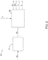
- Fig. 3 is a flowchart illustrating an ultrasonic roller burnishing method 50 for machining a workpiece with an ultrasonic roller burnishing device, in accordance with an exemplary embodiment of the present invention, wherein the ultrasonic roller burnishing device comprises a roller and a motion unit.
- the method 50 comprising steps 51-55. While the actions of the method 50 are illustrated as functional blocks, the order of the blocks and the separation of the actions among the various blocks shown in FIG. 3 are not intended to be limiting. For example, the blocks may be performed in a different order and an action associated with one block may be combined with one or more other blocks or may be sub-divided into a number of blocks.
- an expected residual compressive stress of the workpiece is determined according to practical needs.
- the expected residual compressive stress refers to an expected status of the residual compressive stress desired to be induced, which may comprise a value of the residual compressive stress at a certain depth, a distribution of the residual compressive stress in a certain depth range, an average value of the residual compressive stresses in a certain depth range, or a combination thereof.
- step 52 the motion unit presses the roller of the ultrasonic roller burnishing device against a surface of the workpiece to a pressing depth and drives the roller to roll on the surface at a feed rate.
- the motion unit is driven by a drive motor.
- the motion unit drives the roller to roll on the surface along a preset path.
- the roller vibrates at an ultrasonic frequency under a back pressure, wherein the vibrating of the roller is driven by an ultrasonic vibration unit with an input current inputted thereinto.
- An amplitude or intensity of the vibrating may be adjusted by changing a frequency or an amplitude of the input current.
- the vibrating of the roller is in a direction perpendicular to the surface.
- the back pressure exerted on the roller is generated by a back pressure device.
- step 54 a real time output power of the drive motor is detected.
- the output power of the drive motor can indicate the induced residual compressive stress, so the residual compressive stress can be controlled by controlling the output power of the drive motor.
- step 55 at least one of the pressing depth, the back pressure, the input current and the feed rate is adjusted based on the expected residual compressive stress determined in step 51 and the real time output power of the drive motor detected in step 54, in order to generate a residual compressive stress in the workpiece which is in an expected range predetermined based on the expected residual compressive stress.
- the method further comprises calculating an expected output power based on the expected residual compressive stress.
- the adjusting comprises adjusting the at least one of the pressing depth, the back pressure, the input current and the feed rate based on the expected output power and the real time output power. Specifically, when the expected output power is higher than the real time output power, the adjusting comprises increasing at least one of the pressing depth, the back pressure and the input current, and/or decreasing the feed rate. When the expected output power is lower than the real time output power, the adjusting comprises decreasing at least one of the pressing depth, the back pressure and the input current, and/or increasing the feed rate.
- step 55 further comprises calculating at least one of an expected pressing depth, an expected back pressure, an expected input current and an expected feed rate based on the expected residual compressive stress and the real time output power, and then adjusting the at least one of the pressing depth, the back pressure, the input current and the feed rate according to the at least one of the expected pressing depth, the expected back pressure, the expected input current and the expected feed rate.
- the calculating of the at least one of the expected pressing depth, the expected back pressure, the expected input current and the expected feed rate comprises calculating an expected output power based on the expected residual compressive stress; and calculating the at least one of the expected pressing depth, the expected back pressure, the expected input current and the expected feed rate based on the expected output power and the real time output power.
- step 55 comprises calculating the expected pressing depth, the expected back pressure, the expected input current and the expected feed rate, and then adjusting the pressing depth, the back pressure, the input current and the feed rate according to the expected pressing depth, the expected back pressure, the expected input current and the expected feed rate.
- a plurality of sets of the expected pressing depth, the expected back pressure, the expected input current and the expected feed rate may be obtained based on the expected residual compressive stress and the real time output power. The optimal set of them can be selected as the adjusting basis, according to the practical needs.
- only a part of the four parameters i.e., the pressing depth, the back pressure, the input current and the feed rate, are selected to be adjusted.
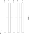
- Fig. 4 is a flowchart illustrating an ultrasonic roller burnishing method 60 in accordance with another exemplary embodiment of the present invention.
- Steps 61-64 are respectively similar with steps 51-54 of the method 50 illustrated in Fig. 3 , which will not be repeated here.
- step 65 at least one of the real time pressing depth, the real time back pressure, the real time input current and the real time feed rate is detected.
- the detected real time parameter(s) will be used as the adjusting basis for other parameters, as well as the expected residual compressive stress and the real time output power.
- step 66 at least one of the pressing depth, the back pressure, the input current and the feed rate is adjusted based on the expected residual compressive stress, the real time output power, and the real time parameter(s) obtained in step 65.
- the real time input current is detected in step 65.
- the pressing depth, the back pressure, and the feed rate are adjusted based on the expected residual compressive stress, the real time output power and the real time input current.
- an expected pressing depth, an expected back pressure and an expected feed rate are calculated based on the expected residual compressive stress, the real time output power and the real time input current, and then the pressing depth, the back pressure and the feed rate are adjusted according to the expected pressing depth, the expected back pressure and the expected feed rate.
- Embodiments of the present invention also refer to a method for machining a component, which can be widely applied in manufacture of turbine blade or aircraft blade.
- the method comprises determining an expected distribution of residual compressive stress of the component, wherein the expected distribution comprising location information of at least one expected area on the component and an expected residual compressive stress corresponding to the expected area.
- the method further comprises processing the expected area with an ultrasonic roller burnishing device comprising a roller, to generate a residual compressive stress in the expected area which is in an expected range predetermined based on the corresponding expected residual compressive stress, in such a manner that a desired distribution of residual compressive stress can be induced in the component.
- Fig. 5 is a flowchart illustrating a method 70 for machining a component in accordance with an exemplary embodiment of the present invention.
- the method 70 comprises steps 71-73.
- an expected distribution of residual compressive stress of the component is determined.
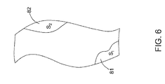
- the expected distribution comprises location information of a first expected area 81 on the component, a first expected residual compressive stress S 1 corresponding to the first expected area 81, location information of a second expected area 82 on the component, and a second expected residual compressive stress S 2 corresponding to the second expected area 82.
- step 72 the first expected area 81 is machined to generate a first residual compressive stress in the first expected area which is in a first expected range predetermined based on the first expected residual compressive stress S 1 .
- step 73 the second expected area 82 is machined to generate a second residual compressive stress in the second expected area which is in a second expected range predetermined based on the second expected residual compressive stress S 2 .
- Step 72 or 73 comprises pressing the roller against a surface of the expected area to a pressing depth; driving the roller to roll on the surface at a feed rate by a motion unit which is driven by a drive motor; vibrating the roller at an ultrasonic frequency under a back pressure, wherein the vibrating of the roller is driven by an input current; and adjusting at least one of the pressing depth, the back pressure, the input current and the feed rate based on the expected residual compressive stress and a real time output power of the drive motor.
Landscapes
- Engineering & Computer Science (AREA)
- Mechanical Engineering (AREA)
- Chemical & Material Sciences (AREA)
- Crystallography & Structural Chemistry (AREA)
- Materials Engineering (AREA)
- Metallurgy (AREA)
- Organic Chemistry (AREA)
- Finish Polishing, Edge Sharpening, And Grinding By Specific Grinding Devices (AREA)
- Grinding And Polishing Of Tertiary Curved Surfaces And Surfaces With Complex Shapes (AREA)
Claims (10)
- System zum Ultraschallglattwalzen (10), umfassend:eine Walze (26), die konfiguriert ist, gegen eine Oberfläche eines Werkstücks bis auf eine Presstiefe gedrückt zu werden, auf der Oberfläche mit einer Vorschubgeschwindigkeit zu rollen und bei einer Ultraschallfrequenz unter einem Gegendruck zu vibrieren, wobei die Walze (26) durch eine Bewegungseinheit gedrückt und gerollt wird, die von einem Antriebsmotor (28) angetrieben wird, und das Vibrieren der Walze (26) durch eine Ultraschallvibrationseinheit (22) mit einem darin zugeführten Eingangsstrom angetrieben wird;dadurch gekennzeichnet, dass das System zum Ultraschallglattwalzen ferner umfasst;
eine Steuerung (30), die konfiguriert ist, mindestens eines von der Presstiefe, dem Gegendruck, dem Eingangsstrom und der Vorschubgeschwindigkeit basierend auf einer erwarteten Druckeigenspannung und einer Echtzeitausgangsleistung des Antriebsmotors (28) einzustellen, um eine Druckeigenspannung in dem Werkstück zu erzeugen, die sich in einem erwarteten Bereich befindet, der basierend auf der erwarteten Druckeigenspannung vorgegeben ist. - System nach Anspruch 1, wobei die Steuerung (30) konfiguriert ist, mindestens eines von einer erwarteten Presstiefe, einem erwarteten Gegendruck, einem erwarteten Eingangsstrom und einer erwarteten Vorschubgeschwindigkeit basierend auf der erwarteten Druckeigenspannung und der Echtzeitausgangsleistung zu berechnen und das mindestens eine von der Presstiefe, dem Gegendruck, dem Eingangsstrom und der Vorschubgeschwindigkeit gemäß dem mindestens einen von der erwarteten Presstiefe, dem erwarteten Gegendruck, dem erwarteten Eingangsstrom und der erwarteten Vorschubgeschwindigkeit anzupassen.
- System nach Anspruch 2, wobei die Steuerung (30) umfasst:einen ersten Rechner (31), der konfiguriert ist, eine erwartete Ausgangsleistung basierend auf der erwarteten Druckeigenspannung zu berechnen; undeinen zweiten Rechner (32), der konfiguriert ist, das mindestens eine von der erwarteten Presstiefe, dem erwarteten Gegendruck, dem erwarteten Eingangsstrom und der erwarteten Vorschubgeschwindigkeit basierend auf der erwarteten Ausgangsleistung und der Echtzeitausgangsleistung zu berechnen.
- Verfahren zum Ultraschallglattwalzen (50, 60), umfassend:Drücken (52, 62) einer Walze (26) gegen eine Oberfläche eines Werkstücks bis auf eine Presstiefe und Antreiben der Walze (26), um auf der Oberfläche mit einer Vorschubgeschwindigkeit durch eine Bewegungseinheit zu rollen, die von einem Antriebsmotor (28) angetrieben wird; undVibrieren (53, 63) der Walze (26) mit einer Ultraschallfrequenz unter einem Gegendruck, wobei das Vibrieren der Walze (26) durch eine Ultraschallvibrationseinheit (22) mit einem darin zugeführten Eingangsstrom angetrieben wird; dadurch gekennzeichnet, dass das Verfahren zum Ultraschallglattwalzen ferner umfasst;Einstellen (55, 65) mindestens eines von der Presstiefe, dem Gegendruck, dem Eingangsstrom und der Vorschubgeschwindigkeit basierend auf einer erwarteten Druckeigenspannung und einer Echtzeitausgangsleistung des Antriebsmotors (28), um eine Druckeigenspannung in dem Werkstück zu erzeugen, die in einem erwarteten Bereich liegt, der basierend auf der erwarteten Druckeigenspannung vorgegeben ist.
- Verfahren nach Anspruch 4, wobei das Einstellen umfasst:Berechnen mindestens eines von einer erwarteten Presstiefe, einem erwarteten Gegendruck, einem erwarteten Eingangsstrom und einer erwarteten Vorschubgeschwindigkeit basierend auf der erwarteten Druckeigenspannung und der Echtzeitausgangsleistung; undEinstellen des mindestens einen von der Presstiefe, dem Gegendruck, dem Eingangsstrom und der Vorschubgeschwindigkeit gemäß dem mindestens einen von der erwarteten Presstiefe, dem erwarteten Gegendruck, dem erwarteten Eingangsstrom und der erwarteten Vorschubgeschwindigkeit.
- Verfahren nach Anspruch 5, wobei das Berechnen umfasst:Berechnen einer erwarteten Ausgangsleistung basierend auf der erwarteten Druckeigenspannung; undBerechnen des mindestens einen von der erwarteten Presstiefe, dem erwarteten Gegendruck, dem erwarteten Eingangsstrom und der erwarteten Vorschubgeschwindigkeit basierend auf der erwarteten Ausgangsleistung und der Echtzeitausgangsleistung.
- Verfahren nach Anspruch 4, wobei das Einstellen umfasst: Einstellen (66) von mindestens einem von der Presstiefe, dem Gegendruck, dem Eingangsstrom und der Vorschubgeschwindigkeit basierend auf der erwarteten Druckeigenspannung, der Echtzeitausgangsleistung und mindestens einem von einer Echtzeitpresstiefe, einem Echtzeitgegendruck, einem Echtzeiteingangsstrom und einer Echtzeitvorschubgeschwindigkeit.
- Verfahren nach Anspruch 7, wobei das Einstellen umfasst:Berechnen einer erwarteten Presstiefe, eines erwarteten Gegendrucks und einer erwarteten Vorschubgeschwindigkeit basierend auf der erwarteten Druckeigenspannung, der Echtzeitausgangsleistung und dem Echtzeiteingangsstrom; undEinstellen der Presstiefe, des Gegendrucks und der Vorschubgeschwindigkeit gemäß der erwarteten Presstiefe, dem erwarteten Gegendruck und der erwarteten Vorschubgeschwindigkeit.
- Verfahren (70) zum Bearbeiten eines Bauteils, umfassend:Bestimmen (71) einer erwarteten Verteilung von Druckeigenspannung des Bauteils, wobei die erwartete Verteilung Positionsinformationen von mindestens einem erwarteten Gebiet (81, 82) auf dem Bauteil und eine erwartete Druckeigenspannung umfasst, die dem erwarteten Gebiet zugehörig ist; undBearbeiten (72) des erwarteten Gebiets (81, 82) mit einer Vorrichtung zum Ultraschallglattwalzen, die eine Walze (26) umfasst, um eine Druckeigenspannung in dem erwarteten Gebiet zu erzeugen, die in einem erwarteten Bereich liegt, der basierend auf der zugehörigen erwarteten Druckeigenspannung vorgegeben ist, umfassend:Drücken der Walze (26) gegen eine Oberfläche des erwarteten Gebiets (81, 82) bis auf eine Presstiefe und Antreiben der Walze, um auf der Oberfläche mit einer Vorschubgeschwindigkeit durch eine Bewegungseinheit zu rollen, die durch einen Antriebsmotor (28) angetrieben wird,Vibrieren der Walze (26) mit einer Ultraschallfrequenz unter einem Gegendruck, wobei das Vibrieren der Walze (26) durch eine Ultraschallvibrationseinheit (22) mit einem darin zugeführten Eingangsstrom angetrieben wird, undEinstellen mindestens eines von der Presstiefe, dem Gegendruck, dem Eingangsstrom und der Vorschubgeschwindigkeit basierend auf der erwarteten Druckeigenspannung und einer Echtzeitausgangsleistung des Antriebsmotors (28).
- Verfahren nach Anspruch 9, wobei die erwartete Verteilung Positionsinformationen eines ersten erwarteten Gebiets (81) und einer ersten erwarteten Druckeigenspannung, die dem ersten erwarteten Gebiet zugehörig ist, und Positionsinformationen eines zweiten erwarteten Gebiets (82) und einer zweiten erwarteten Druckeigenspannung umfasst, die dem zweiten erwarteten Gebiet zugehörig ist; und das Erzeugen der Druckeigenspannung umfasst:Bearbeiten (72) des ersten erwarteten Gebiets (81) des Bauteils, um eine erste Druckeigenspannung in dem ersten erwarteten Gebiet zu erzeugen, die in einem ersten erwarteten Bereich liegt, der basierend auf der ersten erwarteten Druckeigenspannung vorgegeben ist; undBearbeiten (73) des zweiten erwarteten Gebiets (82) des Bauteils, um eine zweite Druckeigenspannung in dem zweiten erwarteten Gebiet zu erzeugen, die in einem zweiten erwarteten Bereich liegt, der basierend auf der zweiten erwarteten Druckeigenspannung vorgegeben ist.
Applications Claiming Priority (1)
| Application Number | Priority Date | Filing Date | Title |
|---|---|---|---|
| PCT/CN2017/081353 WO2018191931A1 (en) | 2017-04-21 | 2017-04-21 | Ultrasonic roller burnishing system and method, and method for machining component |
Publications (3)
| Publication Number | Publication Date |
|---|---|
| EP3638449A1 EP3638449A1 (de) | 2020-04-22 |
| EP3638449A4 EP3638449A4 (de) | 2020-11-25 |
| EP3638449B1 true EP3638449B1 (de) | 2023-03-08 |
Family
ID=63855562
Family Applications (1)
| Application Number | Title | Priority Date | Filing Date |
|---|---|---|---|
| EP17906705.3A Active EP3638449B1 (de) | 2017-04-21 | 2017-04-21 | System und verfahren für ultraschallwalzenbrünieren und verfahren zur bearbeitung eines bauteils |
Country Status (5)
| Country | Link |
|---|---|
| US (1) | US11136635B2 (de) |
| EP (1) | EP3638449B1 (de) |
| JP (1) | JP6972169B2 (de) |
| CN (1) | CN110869163B (de) |
| WO (1) | WO2018191931A1 (de) |
Cited By (1)
| Publication number | Priority date | Publication date | Assignee | Title |
|---|---|---|---|---|
| EP4628257A3 (de) * | 2024-04-02 | 2026-04-22 | RTX Corporation | Mehrachsiges tiefwalzwerkzeug für komplexe randbasis einer hohlen gebläseschaufel zur verbesserung der korrosionsbeständigkeit |
Families Citing this family (12)
| Publication number | Priority date | Publication date | Assignee | Title |
|---|---|---|---|---|
| CN110076350B (zh) * | 2019-04-30 | 2020-05-29 | 北京航空航天大学 | 一种超声冲压式切削挤压一体化加工方法 |
| CN111299959B (zh) * | 2020-03-26 | 2022-02-22 | 山东大学 | 一种超声滚压装置及方法 |
| CN111360147B (zh) * | 2020-04-14 | 2021-07-09 | 太原理工大学 | 一种改善精密箔材表面质量的超声能场装置 |
| CN112877517B (zh) * | 2021-01-14 | 2022-09-13 | 上海交通大学 | 对金属工件施加热场并辅助超声滚压的表面强化装置及方法 |
| CN112877521B (zh) * | 2021-01-14 | 2022-05-27 | 上海交通大学 | 对金属工件施加弹性应力场并辅助超声滚压的表面强化装置及方法 |
| CN114247939B (zh) * | 2021-12-24 | 2023-01-06 | 大连理工大学 | 一种齿轮无载荷整体浸入式化学机械耦合表面抛光方法 |
| CN115536437B (zh) * | 2022-01-18 | 2023-09-08 | 武汉位错科技有限公司 | 一种高温碾压加工方法及其加工装置和应用 |
| CN115369233A (zh) * | 2022-04-07 | 2022-11-22 | 西北工业大学 | 一种消除带内筋筒形件流动旋压残余应力的方法 |
| CN114799728B (zh) * | 2022-05-19 | 2023-08-22 | 南京理工大学 | 一种三维空间梯度结构铝合金的制备系统及方法 |
| CN115922231B (zh) * | 2023-03-10 | 2023-05-09 | 太原理工大学 | 一种集成激光软化和强化技术的旋转超声滚压装置 |
| US20250242396A1 (en) * | 2024-01-26 | 2025-07-31 | Rtx Corporation | Surface treating component with vibration assisted rolling tool |
| CN119282710B (zh) * | 2024-09-29 | 2026-02-10 | 西北工业大学 | 一种在曲面薄壁件表面加工微结构的装置及方法 |
Family Cites Families (20)
| Publication number | Priority date | Publication date | Assignee | Title |
|---|---|---|---|---|
| JPS6234678Y2 (de) * | 1981-04-24 | 1987-09-03 | ||
| JPH01199758A (ja) * | 1988-02-04 | 1989-08-11 | Toyoda Mach Works Ltd | 超音波加工機 |
| US6932876B1 (en) * | 1998-09-03 | 2005-08-23 | U.I.T., L.L.C. | Ultrasonic impact machining of body surfaces to correct defects and strengthen work surfaces |
| US6415486B1 (en) * | 2000-03-01 | 2002-07-09 | Surface Technology Holdings, Ltd. | Method and apparatus for providing a residual stress distribution in the surface of a part |
| KR100316003B1 (ko) * | 2000-07-13 | 2001-12-20 | 편영식 | 초음파를 이용한 마이크로 버니싱 장치 |
| CN101130828B (zh) * | 2006-08-25 | 2010-05-12 | 中国人民解放军装甲兵工程学院 | 超声深滚和滚光一体化表面强化装置 |
| CN201020638Y (zh) | 2007-04-10 | 2008-02-13 | 哈尔滨工大奥瑞德光电技术有限公司 | 超声振动磨削复合加工工具 |
| KR100894499B1 (ko) * | 2008-05-14 | 2009-04-22 | (주)디자인메카 | 초음파 나노 개질기를 이용한 베어링 가공장치 및 가공방법 |
| DE102008032919B4 (de) * | 2008-07-12 | 2018-11-29 | MTU Aero Engines AG | Verfahren zum Oberflächenverfestigen eines Bauteils |
| PL215072B1 (pl) * | 2009-12-29 | 2013-10-31 | Inst Obrobki Plastycznej | Zespól do obróbki powierzchniowej warstw wierzchnich, zwlaszcza metalu |
| WO2011115667A1 (en) * | 2010-03-15 | 2011-09-22 | Scheel Jeremy E | Metallic components for use in corrosive environments and method of manufacturing |
| DE102010048638B4 (de) * | 2010-07-16 | 2017-10-05 | Sauer Ultrasonic Gmbh | Werkzeugmaschine, Werkstückbearbeitungsverfahren |
| DE102010048636B4 (de) * | 2010-10-15 | 2017-11-16 | Sauer Ultrasonic Gmbh | Werkzeugmaschine und Verfahren zur Bearbeitung eines Werkstücks mit einem Werkzeug |
| GB201112696D0 (en) * | 2011-07-25 | 2011-09-07 | Rolls Royce Plc | A method of treating an aerofoil |
| CN104470664A (zh) * | 2012-07-23 | 2015-03-25 | 大西一正 | 装备刀具的超声波振动体的支承结构 |
| CN104249234A (zh) * | 2013-06-27 | 2014-12-31 | 王培涛 | 一种金属表面加工装置 |
| KR101579943B1 (ko) * | 2013-11-29 | 2015-12-28 | 한국기계연구원 | 초음파 진동자를 이용한 가공대상물의 표면 처리 장치 |
| CN105689959A (zh) * | 2016-04-26 | 2016-06-22 | 吉林大学 | 可自动调控静压力的超声表面滚压加工反馈系统 |
| CN105855792A (zh) * | 2016-06-16 | 2016-08-17 | 吉林大学 | 具有可控时变静压力的超声表面滚压装置 |
| CN206065803U (zh) * | 2016-08-30 | 2017-04-05 | 南京国际船舶设备配件有限公司 | 一种表面滚压硬化装置 |
-
2017
- 2017-04-21 JP JP2019555210A patent/JP6972169B2/ja active Active
- 2017-04-21 EP EP17906705.3A patent/EP3638449B1/de active Active
- 2017-04-21 CN CN201780089436.4A patent/CN110869163B/zh active Active
- 2017-04-21 WO PCT/CN2017/081353 patent/WO2018191931A1/en not_active Ceased
- 2017-04-21 US US16/606,854 patent/US11136635B2/en active Active
Cited By (1)
| Publication number | Priority date | Publication date | Assignee | Title |
|---|---|---|---|---|
| EP4628257A3 (de) * | 2024-04-02 | 2026-04-22 | RTX Corporation | Mehrachsiges tiefwalzwerkzeug für komplexe randbasis einer hohlen gebläseschaufel zur verbesserung der korrosionsbeständigkeit |
Also Published As
| Publication number | Publication date |
|---|---|
| JP6972169B2 (ja) | 2021-11-24 |
| CN110869163A (zh) | 2020-03-06 |
| CN110869163B (zh) | 2022-04-26 |
| EP3638449A1 (de) | 2020-04-22 |
| US11136635B2 (en) | 2021-10-05 |
| US20200048725A1 (en) | 2020-02-13 |
| EP3638449A4 (de) | 2020-11-25 |
| JP2020517469A (ja) | 2020-06-18 |
| WO2018191931A1 (en) | 2018-10-25 |
Similar Documents
| Publication | Publication Date | Title |
|---|---|---|
| EP3638449B1 (de) | System und verfahren für ultraschallwalzenbrünieren und verfahren zur bearbeitung eines bauteils | |
| KR100316003B1 (ko) | 초음파를 이용한 마이크로 버니싱 장치 | |
| JPS5935743B2 (ja) | 超音波研削加工装置 | |
| US6458225B1 (en) | Ultrasonic machining and reconfiguration of braking surfaces | |
| CN108818310B (zh) | 一种微尺度磨粒修平参数的在线精准控制方法 | |
| Kumar Singh Yadav et al. | Experimental study and parameter design of electro-discharge diamond grinding | |
| CN1067920C (zh) | 横向挤压机和装有这种挤压机的辊轧机 | |
| WO2002003155A1 (en) | Apparatus and method for machining simulation for nc machining | |
| CN109324567A (zh) | 一种超声振动加工工件表面形貌加工及控制方法 | |
| CN107427983B (zh) | 用于磨削具有槽的工件的方法和磨削机 | |
| CN109332820A (zh) | 一种超声振动加工齿轮齿面形貌加工及控制方法 | |
| CN107138915B (zh) | 超声滚压加工系统和方法、零件的加工方法 | |
| CN201143613Y (zh) | 一种振动压光装置 | |
| JP2002524787A (ja) | 旋削動作の適応制御の方法とシステム | |
| CN105751795B (zh) | 基于弹性元件的机器人雕刻方法 | |
| CN109079255A (zh) | 一种超声振动辅助高效滚齿加工的系统及使用方法 | |
| JPS5988994A (ja) | 抄紙機の繊維質ロ−ル組立機構 | |
| US20060174994A1 (en) | Closed-loop control of power used in ultrasonic consolidation | |
| JP4088061B2 (ja) | 振動切削方法および振動切削装置 | |
| US10926380B2 (en) | Clamping device and clamping system using the same | |
| JP2007015036A (ja) | ホーニング加工装置およびホーニング加工方法 | |
| CN110000514A (zh) | 一种超声振动滚压加工装置 | |
| CN217648175U (zh) | 振动珩磨设备 | |
| Popli et al. | Sequential procedure for selecting the ranges of process parameters in rotary ultrasonic machining | |
| RU2685323C1 (ru) | Способ шлифования периферией круга с продольной подачей за несколько ходов с выхаживанием и наложением ультразвуковых колебаний на заготовку |
Legal Events
| Date | Code | Title | Description |
|---|---|---|---|
| STAA | Information on the status of an ep patent application or granted ep patent |
Free format text: STATUS: THE INTERNATIONAL PUBLICATION HAS BEEN MADE |
|
| PUAI | Public reference made under article 153(3) epc to a published international application that has entered the european phase |
Free format text: ORIGINAL CODE: 0009012 |
|
| STAA | Information on the status of an ep patent application or granted ep patent |
Free format text: STATUS: REQUEST FOR EXAMINATION WAS MADE |
|
| 17P | Request for examination filed |
Effective date: 20191018 |
|
| AK | Designated contracting states |
Kind code of ref document: A1 Designated state(s): AL AT BE BG CH CY CZ DE DK EE ES FI FR GB GR HR HU IE IS IT LI LT LU LV MC MK MT NL NO PL PT RO RS SE SI SK SM TR |
|
| AX | Request for extension of the european patent |
Extension state: BA ME |
|
| DAV | Request for validation of the european patent (deleted) | ||
| DAX | Request for extension of the european patent (deleted) | ||
| A4 | Supplementary search report drawn up and despatched |
Effective date: 20201027 |
|
| RIC1 | Information provided on ipc code assigned before grant |
Ipc: B23P 9/04 20060101ALI20201016BHEP Ipc: B24B 1/04 20060101ALI20201016BHEP Ipc: B24B 39/00 20060101ALI20201016BHEP Ipc: B23P 9/02 20060101AFI20201016BHEP Ipc: B24B 39/02 20060101ALI20201016BHEP Ipc: C21D 7/08 20060101ALI20201016BHEP |
|
| GRAP | Despatch of communication of intention to grant a patent |
Free format text: ORIGINAL CODE: EPIDOSNIGR1 |
|
| STAA | Information on the status of an ep patent application or granted ep patent |
Free format text: STATUS: GRANT OF PATENT IS INTENDED |
|
| INTG | Intention to grant announced |
Effective date: 20221117 |
|
| GRAS | Grant fee paid |
Free format text: ORIGINAL CODE: EPIDOSNIGR3 |
|
| GRAA | (expected) grant |
Free format text: ORIGINAL CODE: 0009210 |
|
| STAA | Information on the status of an ep patent application or granted ep patent |
Free format text: STATUS: THE PATENT HAS BEEN GRANTED |
|
| AK | Designated contracting states |
Kind code of ref document: B1 Designated state(s): AL AT BE BG CH CY CZ DE DK EE ES FI FR GB GR HR HU IE IS IT LI LT LU LV MC MK MT NL NO PL PT RO RS SE SI SK SM TR |
|
| REG | Reference to a national code |
Ref country code: GB Ref legal event code: FG4D |
|
| REG | Reference to a national code |
Ref country code: CH Ref legal event code: EP Ref country code: AT Ref legal event code: REF Ref document number: 1552253 Country of ref document: AT Kind code of ref document: T Effective date: 20230315 |
|
| REG | Reference to a national code |
Ref country code: IE Ref legal event code: FG4D |
|
| REG | Reference to a national code |
Ref country code: DE Ref legal event code: R096 Ref document number: 602017066752 Country of ref document: DE |
|
| REG | Reference to a national code |
Ref country code: LT Ref legal event code: MG9D |
|
| REG | Reference to a national code |
Ref country code: NL Ref legal event code: MP Effective date: 20230308 |
|
| PG25 | Lapsed in a contracting state [announced via postgrant information from national office to epo] |
Ref country code: RS Free format text: LAPSE BECAUSE OF FAILURE TO SUBMIT A TRANSLATION OF THE DESCRIPTION OR TO PAY THE FEE WITHIN THE PRESCRIBED TIME-LIMIT Effective date: 20230308 Ref country code: NO Free format text: LAPSE BECAUSE OF FAILURE TO SUBMIT A TRANSLATION OF THE DESCRIPTION OR TO PAY THE FEE WITHIN THE PRESCRIBED TIME-LIMIT Effective date: 20230608 Ref country code: LV Free format text: LAPSE BECAUSE OF FAILURE TO SUBMIT A TRANSLATION OF THE DESCRIPTION OR TO PAY THE FEE WITHIN THE PRESCRIBED TIME-LIMIT Effective date: 20230308 Ref country code: LT Free format text: LAPSE BECAUSE OF FAILURE TO SUBMIT A TRANSLATION OF THE DESCRIPTION OR TO PAY THE FEE WITHIN THE PRESCRIBED TIME-LIMIT Effective date: 20230308 Ref country code: HR Free format text: LAPSE BECAUSE OF FAILURE TO SUBMIT A TRANSLATION OF THE DESCRIPTION OR TO PAY THE FEE WITHIN THE PRESCRIBED TIME-LIMIT Effective date: 20230308 Ref country code: ES Free format text: LAPSE BECAUSE OF FAILURE TO SUBMIT A TRANSLATION OF THE DESCRIPTION OR TO PAY THE FEE WITHIN THE PRESCRIBED TIME-LIMIT Effective date: 20230308 |
|
| REG | Reference to a national code |
Ref country code: AT Ref legal event code: MK05 Ref document number: 1552253 Country of ref document: AT Kind code of ref document: T Effective date: 20230308 |
|
| PG25 | Lapsed in a contracting state [announced via postgrant information from national office to epo] |
Ref country code: SE Free format text: LAPSE BECAUSE OF FAILURE TO SUBMIT A TRANSLATION OF THE DESCRIPTION OR TO PAY THE FEE WITHIN THE PRESCRIBED TIME-LIMIT Effective date: 20230308 Ref country code: NL Free format text: LAPSE BECAUSE OF FAILURE TO SUBMIT A TRANSLATION OF THE DESCRIPTION OR TO PAY THE FEE WITHIN THE PRESCRIBED TIME-LIMIT Effective date: 20230308 Ref country code: GR Free format text: LAPSE BECAUSE OF FAILURE TO SUBMIT A TRANSLATION OF THE DESCRIPTION OR TO PAY THE FEE WITHIN THE PRESCRIBED TIME-LIMIT Effective date: 20230609 Ref country code: FI Free format text: LAPSE BECAUSE OF FAILURE TO SUBMIT A TRANSLATION OF THE DESCRIPTION OR TO PAY THE FEE WITHIN THE PRESCRIBED TIME-LIMIT Effective date: 20230308 |
|
| PG25 | Lapsed in a contracting state [announced via postgrant information from national office to epo] |
Ref country code: SM Free format text: LAPSE BECAUSE OF FAILURE TO SUBMIT A TRANSLATION OF THE DESCRIPTION OR TO PAY THE FEE WITHIN THE PRESCRIBED TIME-LIMIT Effective date: 20230308 Ref country code: RO Free format text: LAPSE BECAUSE OF FAILURE TO SUBMIT A TRANSLATION OF THE DESCRIPTION OR TO PAY THE FEE WITHIN THE PRESCRIBED TIME-LIMIT Effective date: 20230308 Ref country code: PT Free format text: LAPSE BECAUSE OF FAILURE TO SUBMIT A TRANSLATION OF THE DESCRIPTION OR TO PAY THE FEE WITHIN THE PRESCRIBED TIME-LIMIT Effective date: 20230710 Ref country code: EE Free format text: LAPSE BECAUSE OF FAILURE TO SUBMIT A TRANSLATION OF THE DESCRIPTION OR TO PAY THE FEE WITHIN THE PRESCRIBED TIME-LIMIT Effective date: 20230308 Ref country code: CZ Free format text: LAPSE BECAUSE OF FAILURE TO SUBMIT A TRANSLATION OF THE DESCRIPTION OR TO PAY THE FEE WITHIN THE PRESCRIBED TIME-LIMIT Effective date: 20230308 Ref country code: AT Free format text: LAPSE BECAUSE OF FAILURE TO SUBMIT A TRANSLATION OF THE DESCRIPTION OR TO PAY THE FEE WITHIN THE PRESCRIBED TIME-LIMIT Effective date: 20230308 |
|
| REG | Reference to a national code |
Ref country code: DE Ref legal event code: R081 Ref document number: 602017066752 Country of ref document: DE Owner name: GENERAL ELECTRIC TECHNOLOGY GMBH, CH Free format text: FORMER OWNER: GENERAL ELECTRIC COMPANY, SCHENECTADY, NY, US |
|
| PG25 | Lapsed in a contracting state [announced via postgrant information from national office to epo] |
Ref country code: SK Free format text: LAPSE BECAUSE OF FAILURE TO SUBMIT A TRANSLATION OF THE DESCRIPTION OR TO PAY THE FEE WITHIN THE PRESCRIBED TIME-LIMIT Effective date: 20230308 Ref country code: PL Free format text: LAPSE BECAUSE OF FAILURE TO SUBMIT A TRANSLATION OF THE DESCRIPTION OR TO PAY THE FEE WITHIN THE PRESCRIBED TIME-LIMIT Effective date: 20230308 Ref country code: IS Free format text: LAPSE BECAUSE OF FAILURE TO SUBMIT A TRANSLATION OF THE DESCRIPTION OR TO PAY THE FEE WITHIN THE PRESCRIBED TIME-LIMIT Effective date: 20230708 |
|
| REG | Reference to a national code |
Ref country code: CH Ref legal event code: PL |
|
| REG | Reference to a national code |
Ref country code: DE Ref legal event code: R097 Ref document number: 602017066752 Country of ref document: DE |
|
| RAP2 | Party data changed (patent owner data changed or rights of a patent transferred) |
Owner name: GENERAL ELECTRIC TECHNOLOGY GMBH |
|
| PG25 | Lapsed in a contracting state [announced via postgrant information from national office to epo] |
Ref country code: LU Free format text: LAPSE BECAUSE OF NON-PAYMENT OF DUE FEES Effective date: 20230421 |
|
| REG | Reference to a national code |
Ref country code: BE Ref legal event code: MM Effective date: 20230430 |
|
| PLBE | No opposition filed within time limit |
Free format text: ORIGINAL CODE: 0009261 |
|
| STAA | Information on the status of an ep patent application or granted ep patent |
Free format text: STATUS: NO OPPOSITION FILED WITHIN TIME LIMIT |
|
| PG25 | Lapsed in a contracting state [announced via postgrant information from national office to epo] |
Ref country code: MC Free format text: LAPSE BECAUSE OF FAILURE TO SUBMIT A TRANSLATION OF THE DESCRIPTION OR TO PAY THE FEE WITHIN THE PRESCRIBED TIME-LIMIT Effective date: 20230308 |
|
| PG25 | Lapsed in a contracting state [announced via postgrant information from national office to epo] |
Ref country code: SI Free format text: LAPSE BECAUSE OF FAILURE TO SUBMIT A TRANSLATION OF THE DESCRIPTION OR TO PAY THE FEE WITHIN THE PRESCRIBED TIME-LIMIT Effective date: 20230308 Ref country code: MC Free format text: LAPSE BECAUSE OF FAILURE TO SUBMIT A TRANSLATION OF THE DESCRIPTION OR TO PAY THE FEE WITHIN THE PRESCRIBED TIME-LIMIT Effective date: 20230308 Ref country code: LI Free format text: LAPSE BECAUSE OF NON-PAYMENT OF DUE FEES Effective date: 20230430 Ref country code: DK Free format text: LAPSE BECAUSE OF FAILURE TO SUBMIT A TRANSLATION OF THE DESCRIPTION OR TO PAY THE FEE WITHIN THE PRESCRIBED TIME-LIMIT Effective date: 20230308 Ref country code: CH Free format text: LAPSE BECAUSE OF NON-PAYMENT OF DUE FEES Effective date: 20230430 |
|
| 26N | No opposition filed |
Effective date: 20231211 |
|
| REG | Reference to a national code |
Ref country code: IE Ref legal event code: MM4A |
|
| PG25 | Lapsed in a contracting state [announced via postgrant information from national office to epo] |
Ref country code: BE Free format text: LAPSE BECAUSE OF NON-PAYMENT OF DUE FEES Effective date: 20230430 |
|
| REG | Reference to a national code |
Ref country code: GB Ref legal event code: 732E Free format text: REGISTERED BETWEEN 20240222 AND 20240228 |
|
| PG25 | Lapsed in a contracting state [announced via postgrant information from national office to epo] |
Ref country code: IE Free format text: LAPSE BECAUSE OF NON-PAYMENT OF DUE FEES Effective date: 20230421 |
|
| PG25 | Lapsed in a contracting state [announced via postgrant information from national office to epo] |
Ref country code: IE Free format text: LAPSE BECAUSE OF NON-PAYMENT OF DUE FEES Effective date: 20230421 |
|
| PG25 | Lapsed in a contracting state [announced via postgrant information from national office to epo] |
Ref country code: IT Free format text: LAPSE BECAUSE OF FAILURE TO SUBMIT A TRANSLATION OF THE DESCRIPTION OR TO PAY THE FEE WITHIN THE PRESCRIBED TIME-LIMIT Effective date: 20230308 |
|
| PG25 | Lapsed in a contracting state [announced via postgrant information from national office to epo] |
Ref country code: BG Free format text: LAPSE BECAUSE OF FAILURE TO SUBMIT A TRANSLATION OF THE DESCRIPTION OR TO PAY THE FEE WITHIN THE PRESCRIBED TIME-LIMIT Effective date: 20230308 |
|
| PG25 | Lapsed in a contracting state [announced via postgrant information from national office to epo] |
Ref country code: BG Free format text: LAPSE BECAUSE OF FAILURE TO SUBMIT A TRANSLATION OF THE DESCRIPTION OR TO PAY THE FEE WITHIN THE PRESCRIBED TIME-LIMIT Effective date: 20230308 |
|
| PGFP | Annual fee paid to national office [announced via postgrant information from national office to epo] |
Ref country code: DE Payment date: 20250319 Year of fee payment: 9 |
|
| PG25 | Lapsed in a contracting state [announced via postgrant information from national office to epo] |
Ref country code: CY Free format text: LAPSE BECAUSE OF FAILURE TO SUBMIT A TRANSLATION OF THE DESCRIPTION OR TO PAY THE FEE WITHIN THE PRESCRIBED TIME-LIMIT; INVALID AB INITIO Effective date: 20170421 |
|
| PG25 | Lapsed in a contracting state [announced via postgrant information from national office to epo] |
Ref country code: HU Free format text: LAPSE BECAUSE OF FAILURE TO SUBMIT A TRANSLATION OF THE DESCRIPTION OR TO PAY THE FEE WITHIN THE PRESCRIBED TIME-LIMIT; INVALID AB INITIO Effective date: 20170421 |
|
| PG25 | Lapsed in a contracting state [announced via postgrant information from national office to epo] |
Ref country code: TR Free format text: LAPSE BECAUSE OF FAILURE TO SUBMIT A TRANSLATION OF THE DESCRIPTION OR TO PAY THE FEE WITHIN THE PRESCRIBED TIME-LIMIT Effective date: 20230308 |
|
| PGFP | Annual fee paid to national office [announced via postgrant information from national office to epo] |
Ref country code: GB Payment date: 20260319 Year of fee payment: 10 |
|
| PGFP | Annual fee paid to national office [announced via postgrant information from national office to epo] |
Ref country code: FR Payment date: 20260320 Year of fee payment: 10 |