EP3638464B1 - Vorrichtung zur kompensation von fügebewegungen - Google Patents
Vorrichtung zur kompensation von fügebewegungen Download PDFInfo
- Publication number
- EP3638464B1 EP3638464B1 EP18734119.3A EP18734119A EP3638464B1 EP 3638464 B1 EP3638464 B1 EP 3638464B1 EP 18734119 A EP18734119 A EP 18734119A EP 3638464 B1 EP3638464 B1 EP 3638464B1
- Authority
- EP
- European Patent Office
- Prior art keywords
- joining
- unit
- force
- blocking
- component
- Prior art date
- Legal status (The legal status is an assumption and is not a legal conclusion. Google has not performed a legal analysis and makes no representation as to the accuracy of the status listed.)
- Active
Links
Images



Classifications
-
- B—PERFORMING OPERATIONS; TRANSPORTING
- B25—HAND TOOLS; PORTABLE POWER-DRIVEN TOOLS; MANIPULATORS
- B25J—MANIPULATORS; CHAMBERS PROVIDED WITH MANIPULATION DEVICES
- B25J11/00—Manipulators not otherwise provided for
- B25J11/005—Manipulators for mechanical processing tasks
-
- B—PERFORMING OPERATIONS; TRANSPORTING
- B21—MECHANICAL METAL-WORKING WITHOUT ESSENTIALLY REMOVING MATERIAL; PUNCHING METAL
- B21J—FORGING; HAMMERING; PRESSING METAL; RIVETING; FORGE FURNACES
- B21J15/00—Riveting
- B21J15/02—Riveting procedures
- B21J15/025—Setting self-piercing rivets
-
- B—PERFORMING OPERATIONS; TRANSPORTING
- B21—MECHANICAL METAL-WORKING WITHOUT ESSENTIALLY REMOVING MATERIAL; PUNCHING METAL
- B21J—FORGING; HAMMERING; PRESSING METAL; RIVETING; FORGE FURNACES
- B21J15/00—Riveting
- B21J15/10—Riveting machines
-
- B—PERFORMING OPERATIONS; TRANSPORTING
- B21—MECHANICAL METAL-WORKING WITHOUT ESSENTIALLY REMOVING MATERIAL; PUNCHING METAL
- B21J—FORGING; HAMMERING; PRESSING METAL; RIVETING; FORGE FURNACES
- B21J15/00—Riveting
- B21J15/10—Riveting machines
- B21J15/28—Control devices specially adapted to riveting machines not restricted to one of the preceding subgroups
-
- B—PERFORMING OPERATIONS; TRANSPORTING
- B25—HAND TOOLS; PORTABLE POWER-DRIVEN TOOLS; MANIPULATORS
- B25J—MANIPULATORS; CHAMBERS PROVIDED WITH MANIPULATION DEVICES
- B25J11/00—Manipulators not otherwise provided for
- B25J11/005—Manipulators for mechanical processing tasks
- B25J11/007—Riveting
Definitions
- the invention relates to a joining unit for an articulated arm robot for joining a component to a joining element while applying an axial force to the joining element.
- a joining unit for an articulated arm robot for one-sided joining of a component or a component assembly with a joining element while applying an axial force comprises a base element for connection to an articulated arm robot, in particular a flange or another connecting element.
- This base element is connected to a feed unit which is moved relative to the base element in an axial direction in and against the setting direction.
- the feed unit carries a setting device which is moved together with the feed unit.
- the setting device acts on the component via a joining element in order to connect the joining element to the component or the component assembly.
- a pressure piece is also connected to the feed unit, the pressure piece also acting on the component.
- the pressure piece is connected to the feed unit via a coupling unit. If the feed unit now moves towards the component, the pressure piece touches the component.
- the coupling unit is designed as a spiral spring which supports the pressure piece opposite the feed unit.
- the pressure piece When the pressure piece now touches the component, it then exerts a spring force on the component or the component assembly and can thus, for example, fix an upper component layer on a lower component layer with this force.
- the coupling unit comprises a blocking unit which, from a predefined axial blocking position, prevents an axial relative movement in the direction of the feed unit and can thus transmit the force of the feed unit to the component.
- the blocking unit is designed in such a way that it prevents the relative movement of the pressure piece until a blocking force set in the blocking unit is reached. If the blocking force is exceeded, movement can be permitted.
- the blocking unit comprises a release device, through the actuation of which the blocking force can be reduced or completely removed during the process.
- this force can act on the component via the parallel acting setting device via the joining element.
- the release device is activated as soon as the joining element touches the component with its tip.
- the release device preferably acts in such a way that the blocking force that acts between the pressure piece and the feed unit is suddenly set to zero.
- the blocking force is constant during a pretensioning phase.
- the blocking unit can comprise an electric motor, which acts between the feed unit and the pressure piece with the torque required to generate a blocking force and, when the blocking force is reached, for example, can be de-energized so that a relative movement between the pressure piece and the feed unit is made possible.
- the internal resistance of the electric motor when de-energized is considered to be negligible.
- the blocking unit can comprise a pneumatic or hydraulic cylinder.
- the piston of the cylinder can be subjected to the pressure necessary to set the desired blocking force. The piston moves to the stop in the cylinder and prevents compression until the blocking force is reached.
- the cylinder is designed as a pneumatic cylinder, which enables a relative movement of the pressure piece due to the compression of the air from a certain force that goes beyond the preset blocking force. This is sufficient to bridge the path between the pressure piece and the joining element on the setting device.
- the release device is actuated, as a result of which the force generated by the feed unit acts on the joining element via the setting device.
- the blocking unit comprises a valve, in particular a control valve or a pressure relief valve, which is connected to the cylinder.
- a pressure can be set in a defined manner which, even when using incompressible media, allows the piston to move if the force acting on the pressure piece exceeds the blocking force.
- the release device can preferably comprise a vent valve. By using a vent valve, the blocking unit can be released or released quickly and easily.
- the coupling unit can comprise a spring element, in particular a spiral spring, which can be arranged to act parallel to the blocking unit.
- a basic position of the pressure piece relative to the feed unit can be set, in particular if the axial path of the pressure piece away from the feed unit is limited by a stop.
- a first contact can be achieved by the pressure piece due to the spring force, which then allows an axial relative movement of the pressure piece in the direction of the feed unit, the further movement of the pressure piece being prevented when the blocking position is reached.
- the joining unit preferably has a touch-down detection which detects the point in time when the joining element touches the component, whereupon the release device is actuated.
- a touchdown detection is particularly important if, when the blocking force is exceeded, there is a further relative movement between the setting device / feed unit and pressure piece.
- the release device can be actuated, whereby the force of the feed unit is then transmitted to the component exclusively via the setting device and the joining element.
- An offset of the setting device in relation to the component then only takes place after the setting process has taken place.
- the touch-down detection can preferably comprise a force sensor which is connected to the setting device and detects the axial process force on the setting device. If the joining element is placed on the component via the setting device, the force by which the blocking force is exceeded is detected at the force sensor when the feed unit continues to move, so that placing is reliably detected.
- the force sensor can be an axial force sensor comprising a strain gauge.
- the touchdown detection can also be implemented by a position measuring system, if necessary using a corresponding sensor. It can also take place via the drive of the feed unit, for example via an incremental position measuring system.
- the detection can also take place via the drive power of the feed unit.
- the setting device can comprise a rotating spindle which rotates a joining element into a component or a component assembly.
- the rotating spindle is operated in such a way that a speed of 3,000 to 10,000 / min can be achieved in order to establish a friction connection.
- the pressure piece can preferably be designed as a pressure sleeve and be arranged coaxially to the setting device, in particular to the rotating spindle.
- the setting device can thus be guided through the pressure piece, whereby the joining element can be guided and secured during the joining process.
- the feed unit is operated in such a way that the feed force is kept constant during the pretensioning process and after the release device has been actuated. This ensures that the tension in the system between the articulated arm robot and the component remains the same, which largely eliminates any misalignment during the joining process.
- the feed force is kept constant during the entire joining process.
- this relates to a method for joining a component to a joining element using an articulated robot.
- a feed unit for axially inserting a joining element into the component is provided on the articulated robot, the feed unit comprising a setting device which can be equipped with a joining element and which is driven against the component with a pressure piece.
- the articulated arm robot moves when the pressure piece is blocked, the pressure piece with the feed unit being placed against the component at the joining position, the force applied leading to a pretensioning of the articulated arm robot.
- the release device is actuated. The blocking device is thus switched off and a relative movement of the setting device relative to the component is made possible.
- the feed unit acts exclusively on the component via the attached joining element, the attached joining element then being inserted into the component at the rate of the previous blocking force.
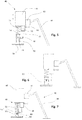
- Fig. 1 shows a joining unit 10 according to the invention, which is fastened to an articulated arm robot 12 shown schematically.
- the joining unit 10 has a base element 13 to which a feed unit 14 is attached.
- the feed unit 14 can be moved in the axial direction relative to the base element 13.
- a setting device which is designed in the form of a rotary spindle 16, is connected to the feed unit 14.
- a coupling unit 17 is provided, acting parallel to the rotating spindle 16, which couples a pressure piece 26 to the feed unit 14.
- the coupling unit 17 comprises a blocking unit which is designed in the form of a pneumatic cylinder 18 which is connected to the feed unit 14.
- a vent valve 20 is provided on the pneumatic cylinder 18, which acts as a release device and can reduce the pressure with which the piston 22 of the cylinder 18 is acted upon.
- a pressure piece 26 is arranged, via which a pressing force can be transmitted to the component 24.
- the blocking position from which the relative movement of the pressure piece 26 below the blocking force is prevented, is permanently set to the maximum extension length of the piston 22.
- the distance of the pressure piece 26 from the feed unit 14 is somewhat greater than the distance of the tip of the joining element 28 fixed on the rotating spindle 16 from the feed unit 14. In the present case, the blocking force is set to 2 kN.
- the pressure in the pneumatic cylinder 18 is set so that up to one applied force of 2kN, a rigid behavior of the pneumatic cylinder can be assumed. Once the blocking force has been reached, the compression of the air in the cylinder can result in a movement of the pressure piece 26 relative to the feed unit 14.
- an attachment socket 25 is connected to the feed unit 14 and the vent valve 20.
- this force is transmitted from the feed unit 14 to the component 24.
- the articulated arm robot 12 is pretensioned, and during this pretensioning process, depending on the angular positions of the articulated arm robot 12, an offset of the pressure piece 26 relative to the component 24 results. In this way, a prestress can be built up before the joining element 28 touches the component 24.
- Fig. 3 shows another position in the setting process.
- the feed unit 14 applies a feed force that exceeds the blocking force of 2 kN. This results in a compression of the fluid in the pressure chamber, although the connected vent valve 20 is still closed.
- the compression of the fluid in the pressure chamber enables a relative movement of the pressure piece 26 with respect to the feed unit 14 until the tip of the joining element 28 touches the component 24. This moment leads to the actuation of the release device in the form of the vent valve 20.
- Fig. 4 shows the state as it occurs after the vent valve 20 has been opened.
- the pressure chamber of the pneumatic cylinder 18 is vented by opening the vent valve 20, as a result of which no more force can be transmitted between the component 24 and the articulated arm robot 12 via the pressure piece 26.
- the force is transmitted exclusively via the joining element 28, which is pressed onto the component 24 via the rotary spindle 16.
- This has the consequence that the joining element 28 is driven into the component 24 with a feed force equal to the blocking force. Since there is an unchanged force ratio between the articulated arm robot 12 and the component 24, the setting process of the joining element 28 can be carried out without an offset occurring during the joining process.
- Fig. 5 shows a schematic view of a further embodiment of a joining unit 40 according to the invention.
- the joining unit 40 comprises a base element 42 which is attached to an articulated arm robot 44.
- the joining unit 40 comprises a feed unit 46 which can be moved in the axial setting direction.
- a coupling device 48 is provided which connects a hollow cylindrical pressure piece 50 to the feed unit 46.
- the Coupling device 48 comprises a spiral spring 52 which lies coaxially with the hollow cylindrical pressure piece 50 and with a rotating spindle 54 guided through the pressure piece 50.
- the coupling device 48 has a blocking unit which is designed in the form of a pneumatic cylinder 56. Analogous to the execution according to Figures 1 to 4 a touch-up socket can also be integrated into the joining unit.
- Fig. 5 the feed unit 46 is moved in a first step against the composite component 58 until the pressure piece 50 is in contact with the composite component. This position is in Fig. 6 shown.
- the spiral spring 52 is compressed with respect to the component assembly 58 until the pneumatic cylinder 56 blocks any further relative movement of the pressure piece 50 in the direction of the feed unit 46. Up to this position only the spring force of the spring 52 acts on the pressure piece 50. As soon as the pressure piece has reached the blocking position and the pneumatic cylinder 56 acts with its preset blocking force, this can be transferred to the component assembly 58. If the feed unit now acts with a force that is slightly greater than the blocking force, the air volume in the cylinder 56 is compressed further with the vent valve 62 closed until the joining element 60 rests on the component assembly, as shown in FIG Fig. 8 is shown.
- the joining element 60 held on the rotating spindle 54 is still located with its tip above the component 58.
- the joining process takes place analogously to that in FIG Figures 1 to 4 described joining process instead.
- a release device is actuated which, according to the present embodiment, is designed as a vent valve 62 and which is vented to release it.
- the pneumatic cylinder 56 is completely and quickly vented and the joining element 60 is driven into the component assembly 58 under rotation and axial force, which roughly corresponds to the predefined blocking force, and in the present case connects the two component layers of the component assembly 58 with one another.
- Fig. 9 shows this final state with the vented cylinder 62, in which the joining element 60 connects the two component layers of the component assembly 58.
Landscapes
- Engineering & Computer Science (AREA)
- Mechanical Engineering (AREA)
- Robotics (AREA)
- Manipulator (AREA)
- Automatic Assembly (AREA)
Description
- Die Erfindung betrifft eine Fügeeinheit für einen Gelenkarmroboter zum Fügen eines Bauteils mit einem Fügeelement unter Aufbringung einer Axialkraft auf das Fügeelement.
- Beim Fügen von Bauteilen mit einem Gelenkarmroboter besteht das Problem, dass während der Aufbringung der Setzkraft, insbesondere bei Reibschweißvorgängen, ein Verkippen des Reibschweißelements stattfindet und dadurch einen orthogonal zur Oberfläche des Bauteils ausgerichteten Setzvorgang erschwert. Auch verliert eine zum Drehantrieb vorgesehene Drehspindel leicht den Eingriff mit den Antriebsstrukturen des Reibschweißelements. Dokument
DE102014015183A1 offenbart den nächstliegenden Stand der Technik. - Es ist Aufgabe der Erfindung, eine Fügeeinheit für einen Gelenkarmroboter bereitzustellen, die ein zuverlässiges Setzen von Fügeelementen unter Axialkraft ermöglicht.
- Eine Fügeeinheit für einen Gelenkarmroboter zum einseitigen Fügen eines Bauteils oder eines Bauteilverbundes mit einem Fügeelement unter Aufbringung einer Axialkraft umfasst ein Grundelement zum Anschluss an einen Gelenkarmroboter, insbesondere einen Flansch oder ein anderes Verbindungselement. Dieses Grundelement ist mit einer Vorschubeinheit verbunden, die relativ zum Grundelement in einer axialen Richtung in und entgegen der Setzrichtung bewegt ist. Die Vorschubeinheit trägt eine Setzeinrichtung, die zusammen mit der Vorschubeinheit bewegt ist. Die Setzeinrichtung wirkt über ein Fügeelement auf das Bauteil, um das Fügeelement mit dem Bauteil oder dem Bauteilverbund zu verbinden. Neben der Setzeinrichtung ist ein Druckstück ebenfalls mit der Vorschubeinheit verbunden, wobei das Druckstück ebenfalls auf das Bauteil wirkt. Das Druckstück ist über eine Koppeleinheit mit der Vorschubeinheit verbunden. Fährt die Vorschubeinheit nun auf das Bauteil zu, setzt das Druckstück auf das Bauteil auf.
- In gängiger Weise ist die Koppeleinheit als Spiralfeder ausgebildet, die das Druckstück gegenüber der Vorschubeinheit lagert. Wenn das Druckstück nun auf das Bauteil aufsetzt, übt dies dann eine Federkraft auf das Bauteil oder den Bauteilverbund aus und kann so beispielsweise eine obere Bauteillage auf einer unteren Bauteillage mit dieser Kraft fixieren.
- Erfindungsgemäß umfasst die Koppeleinheit eine Blockiereinheit, die ab einer vordefinierten axialen Blockierposition eine axiale Relativbewegung in Richtung der Vorschubeinheit verhindert und so die Kraft der Vorschubeinheit auf das Bauteil übertragen kann. Die Blockiereinheit ist derart ausgebildet, dass sie die Relativbewegung des Druckstücks so lange verhindert, bis eine in der Blockiereinheit eingestellte Blockierkraft erreicht ist. Ist die Blockierkraft überschritten, kann eine Bewegung zugelassen werden.
- Ferner umfasst die Blockiereinheit eine Lösevorrichtung, durch deren Betätigung die Blockierkraft während des Prozesses reduziert bzw. vollständig weggenommen werden kann.
- In dem Maße, in dem die blockierte Kraft reduziert wird, kann diese Kraft über die parallel wirkende Setzeinrichtung über das Fügeelement auf das Bauteil wirken.
- Die Lösevorrichtung wird aktiviert, sobald das Fügeelement mit seiner Spitze auf das Bauteil aufsetzt.
- Bevorzugt wirkt die Lösevorrichtung derart, dass die Blockierkraft, die zwischen Druckstück und Vorschubeinheit wirkt, schlagartig auf Null gesetzt wird. insbesondere ist die Blockierkraft während einer Vorspannphase konstant.
- Durch das Beaufschlagen des Gelenkarmroboters mit der nachfolgend umzusetzenden Prozesskraft wird eine zusätzliche Relativbewegung zwischen dem Gelenkarmroboter und dem Bauteil verhindert. Dadurch wird während des Fügeprozesses ein Kippen des Fügeelements mit seinen negativen Auswirkungen auf das Fügeergebnis verhindert.
- Gemäß einer ersten Ausführungsform kann die Blockiereinheit einen Elektromotor umfassen, der zwischen der Vorschubeinheit und dem Druckstück mit dem für die Erzeugung einer Blockierkraft notwendigen Drehmoment wirkt und bei Erreichen der Blockierkraft beispielsweise stromlos geschalten werden kann, sodass eine Relativbewegung zwischen Druckstück und Vorschubeinheit ermöglicht wird. Der innere Widerstand des Elektromotors im stromlosen Zustand wird als vernachlässigbar angesehen.
- Gemäß einer weiteren Ausgestaltung kann die Blockiereinheit einen pneumatischen oder hydraulischen Zylinder umfassen. Der Kolben des Zylinders kann in dieser Ausführungsform mit dem für die Einstellung der gewünschten Blockierkraft notwendigen Druck beaufschlagt werden, Der Kolben fährt dabei im Zylinder auf Anschlag und vermeidet eine Kompression bis zum Erreichen der Blockierkraft.
- Insbesondere ist der Zylinder als pneumatischer Zylinder ausgebildet, wodurch ab einer bestimmten Kraft, die über die voreingestellte Blockierkraft hinausgeht, eine Relativbewegung des Druckstücks aufgrund der Kompression der Luft ermöglicht wird. Dies ist ausreichend, um den Weg zwischen dem Druckstück und dem Fügeelement an der Setzeinrichtung zu überbrücken. Wie bereits erwähnt, wird bei Aufsetzen des Fügeelements die Lösevorrichtung betätigt, wodurch die von der Vorschubeinheit erzeugte Kraft über die Setzeinrichtung auf das Fügeelement wirkt.
- Gemäß einer weiteren vorteilhaften Ausgestaltung kann vorgesehen sein, dass die Blockiereinheit ein Ventil, insbesondere ein Regelventil oder ein Überdruckventil, umfasst, das mit dem Zylinder verbunden ist. Auf diese Weise kann definiert ein Druck eingestellt werden, der auch bei Verwendung von inkompressiblen Medien eine Bewegung des Kolbens erlaubt, wenn die auf das Druckstück wirkende Kraft die Blockierkraft übersteigt.
- Bevorzugt kann die Lösevorrichtung ein Entlüftungsventil umfassen. Durch die Verwendung eines Entlüftungsventils kann eine schnelle und einfache Freigabe bzw. ein Lösen der Blockiereinheit erfolgen.
- Die Koppeleinheit kann ein Federelement, insbesondere eine Spiralfeder, umfassen, die parallel zur Blockiereinheit wirkend angeordnet sein kann. Auf diese Weise kann eine Grundstellung des Druckstücks gegenüber der Vorschubeinheit eingestellt werden, insbesondere wenn der axiale Weg des Druckstücks von der Vorschubeinheit weg durch einen Anschlag begrenzt wird. Auf diese Weise kann eine erste Anlage durch das Druckstück aufgrund der Federkraft erreicht werden, die dann eine axiale Relativbewegung des Druckstücks in Richtung der Vorschubeinheit zulässt, wobei dann bei Erreichen der Blockierposition die Weiterbewegung des Druckstücks verhindert wird.
- Bevorzugt weist die Fügeeinheit eine Aufsetzerfassung auf, die den Zeitpunkt des Aufsetzens des Fügeelements auf das Bauteil erfasst, woraufhin die Löseeinrichtung betätigt wird. Eine Aufsetzerfassung ist insbesondere dann von Bedeutung, wenn bei Überschreiten der Blockierkraft eine weitere Relativbewegung zwischen Setzeinrichtung / Vorschubeinheit und Druckstück erfolgt.
- Wird dann durch die Aufsetzerfassung ein Aufsetzen des Fügeelements auf dem Bauteil detektiert, kann die Lösevorrichtung betätigt werden, wodurch die Kraft der Vorschubeinheit dann ausschließlich über die Setzeinrichtung und das Fügeelement auf das Bauteil übertragen wird. Ein Versatz der Setzeinrichtung zum Bauteil erfolgt dann erst nach erfolgtem Setzvorgang.
- Bevorzugt kann die Aufsetzerfassung einen Kraftsensor umfassen, der mit der Setzeinrichtung verbunden ist und die axiale Prozesskraft auf die Setzeinrichtung erfasst. Wird das Fügeelement über die Setzeinrichtung auf das Bauteil aufgesetzt, wird bei Weiterbewegung der Vorschubeinheit die Kraft, um die die Blockierkraft überschritten wird, am Kraftsensor detektiert, wodurch ein Aufsetzen zuverlässig erkannt wird. Der Kraftsensor kann ein Axialkraftsensor umfassend einen Dehnmessstreifen sein.
- Die Aufsetzerfassung kann auch durch ein Wegmesssystem ggfs. unter Verwendung eines entsprechenden Sensors umgesetzt sein. Sie kann auch über den Antrieb der Vorschubeinheit erfolgen, beispielsweise über ein inkrementelles Wegmesssystem.
- Alternativ kann die Erfassung auch über die Antriebsleistung der Vorschubeinheit erfolgen.
- Die Setzeinrichtung kann eine Drehspindel umfassen, die ein Fügeelement unter Rotation in ein Bauteil oder einen Bauteilverbund einbringt.
- Die Drehspindel wird derart betrieben, dass eine Drehzahl von 3.000 bis 10.000 /min erreicht werden kann, um eine Reibverbindung herzustellen.
- Das Druckstück kann bevorzugt als Druckhülse ausgebildet sein und koaxial zur Setzeinrichtung, insbesondere zur Drehspindel angeordnet sein. Somit kann die Setzeinrichtung durch das Druckstück geführt werden, wodurch eine Führung und Sicherung des Fügeelements während des Fügevorgangs erfolgen kann.
- Insbesondere wird die Vorschubeinheit derart betrieben, dass die Vorschubkraft während des Vorspannvorgangs und nach dem Betätigen der Lösevorrichtung konstant gehalten wird. Dadurch wird gewährleistet, dass die Spannung im System zwischen Gelenkarmroboter und Bauteil gleich bleibt, wodurch ein Versatz beim Fügevorgang weitestgehend eliminiert werden kann.
- Insbesondere wird die Vorschubkraft während des gesamten Fügevorgangs konstant gehalten. Dies hat den Vorteil, dass die Summe der in Fügerichtung wirkenden Kräfte (z.B. Prozesskraft, Blockierkraft etc.) exakt der Kraft entspricht, mit der der Gelenkarmroboter vorgespannt ist.
- Gemäß einem weiteren Aspekt der Erfindung betrifft diese ein Verfahren zum Fügen eines Bauteils mit einem Fügeelement unter Verwendung eines Gelenkroboters. An dem Gelenkroboter ist eine Vorschubeinheit zum axialen Einbringen eines Fügeelements in das Bauteil vorgesehen, wobei die Vorschubeinheit eine Setzeinrichtung umfasst, die mit einem Fügeelement bestückbar ist und mit einem Druckstück gegen das Bauteil gefahren wird. Der Gelenkarmroboter verfährt bei blockiertem Druckstück, wobei das Druckstück mit der Vorschubeinheit gegen das Bauteil an der Fügeposition aufgesetzt wird, wobei die aufgebrachte Kraft zu einem Vorspannen des Gelenkarmroboters führt. Ist die Blockierkraft erreicht und liegt das Fügeelement an der Oberfläche des Bauteils oder des Bauteilverbunds auf, wird die Lösevorrichtung betätigt. Die Blockiervorrichtung wird damit ausgeschaltet und eine Relativbewegung der Setzeinrichtung relativ zum Bauteil ermöglicht.
- Dadurch wirkt nach dem Lösen der Blockierkraft die Vorschubeinheit ausschließlich über das aufgesetzte Fügeelement auf das Bauteil, wobei das aufgesetzte Fügeelement dann mit dem Vorschub in Höhe der vormaligen Blockierkraft in das Bauteil eingesetzt wird.
- Da sich dadurch die Kraft, die auf das Bauteil wirkt, während des Fügevorgangs nicht ändert, kann ein Versatz der Setzeinrichtung zum Bauteil bis zum Abschluss des Fügevorgangs verhindert werden. So kann ein zuverlässiger und präziser Setzvorgang gewährleistet werden.
- Weitere Vorteile, Merkmale und Anwendungsmöglichkeiten der vorliegenden Erfindung ergeben sich aus der nachfolgenden Beschreibung in Verbindung mit den in den Zeichnungen dargestellten Ausführungsbeispielen.
-
- Fig. 1
- ein erster Prozessschritt einer schematisch dargestellten erfindungsgemäßen Anordnung;
- Fig. 2
- ein zweiter Prozessschritt einer schematisch dargestellten erfindungsgemäßen Anordnung;
- Fig. 3
- ein dritter Prozessschritt einer schematisch dargestellten erfindungsgemäßen Anordnung;
- Fig. 4
- ein vierter Prozessschritt einer schematisch dargestellten erfindungsgemäßen Anordnung;
- Fig. 5
- ein erster Prozessschritt, einer weiteren erfindungsgemäßen Ausführungsform einer schematisch dargestellten Anordnung;
- Fig. 6
- ein Zustand nach dem ersten Prozessschritt der erfindungsgemäßen Ausführungsform:
- Fig. 7
- ein zweiter Prozessschritt einer weiteren erfindungsgemäßen Ausführungsform einer schematisch dargestellten Anordnung;
- Fig. 8
- ein Zustand nach dem zweiten Prozessschritt der erfindungsgemäßen Ausführungsform; und
- Fig. 9
- ein Endzustand des Fügevorgangs einer weiteren erfindungsgemäßen Ausführungsform einer schematisch dargestellten Anordnung.
-
Fig. 1 zeigt eine erfindungsgemäße Fügeeinheit 10, die an einem schematisch dargestellten Gelenkarmroboter 12 befestigt ist. Die Fügeeinheit 10 weist ein Grundelement 13 auf, an welchem eine Vorschubeinheit 14 befestigt ist. Die Vorschubeinheit 14 ist in axialer Richtung relativ zum Grundelement 13 bewegbar. Mit der Vorschubeinheit 14 ist eine Setzeinrichtung, die in Form einer Drehspindel 16 ausgebildet ist, verbunden. Ferner ist parallel wirkend zur Drehspindel 16 eine Koppeleinheit 17 vorgesehen, die ein Druckstück 26 an die Vorschubeinheit 14 koppelt. Die Koppeleinheit 17 umfasst eine Blockiereinheit, die in Form eines pneumatischen Zylinders 18 ausgebildet ist, der an der Vorschubeinheit 14 angebunden ist. An dem pneumatischen Zylinder 18 ist ein Entlüftungsventil 20 vorgesehen, das als Lösevorrichtung wirkt und den Druck, mit dem der Kolben 22 des Zylinders 18 beaufschlagt wird, abbauen kann. Am Ende des Kolbens 22, das einem Bauteil 24 zugewandt ist, ist ein Druckstück 26 angeordnet, über welches eine Presskraft auf das Bauteil 24 übertragen werden kann. Gemäß dem vorliegenden Ausführungsbeispiel ist die Blockierposition, ab welcher die Relativbewegung des Druckstücks 26 unterhalb der Blockierkraft unterbunden wird, fest auf die maximale Auszugslänge des Kolbens 22 eingestellt. Die Entfernung des Druckstücks 26 von der Vorschubeinheit 14 ist dabei etwas größer als die Entfernung der Spitze des an der Drehspindel 16 festgelegten Fügeelements 28 von der Vorschubeinheit 14. Im vorliegenden Fall ist die Blockierkraft auf 2 kN eingestellt. Der Druck im pneumatischen Zylinder 18 ist dabei so eingestellt, dass bis zu einer anliegenden Kraft von 2kN von einem starren Verhalten des pneumatischen Zylinders ausgegangen werden kann. Ab Erreichen der Blockierkraft kann durch die Kompression der Luft im Zylinder eine Relativbewegung des Druckstücks 26 zur Vorschubeinheit 14 stattfinden. Zudem ist eine Aufsetzerfassung 25 mit der Vorschubeinheit 14 und dem Entlüftungsventil 20 verbunden. - Wie
Fig. 2 weiter zeigt, wird diese Kraft von der Vorschubeinheit 14 auf das Bauteil 24 übertragen. Dadurch wird der Gelenkarmroboter 12 vorgespannt, wobei sich während dieses Vorspannvorgangs abhängig von den Winkelstellungen des Gelenkarmroboters 12 ein Versatz des Druckstücks 26 zum Bauteil 24 ergibt. Auf diese Weise kann eine Vorspannung aufgebaut werden, bevor das Fügeelement 28 auf das Bauteil 24 aufsetzt. -
Fig. 3 zeigt eine weitere Stellung im Setzvorgang. Die Vorschubeinheit 14 bringt in dieser Phase des Fügeprozesses eine die Blockierkraft von 2 kN überschreitende Vorschubkraft auf. Dadurch erfolgt eine Kompression des Fluids in der Druckkammer, obwohl das angeschlossene Entlüftungsventil 20 noch geschlossen ist. Durch die Kompression des Fluids in der Druckkammer wird eine Relativbewegung des Druckstücks 26 gegenüber der Vorschubeinheit 14 insoweit ermöglicht, bis die Spitze des Fügeelements 28 auf das Bauteil 24 aufsetzt. Dieser Moment führt zur Betätigung der Lösevorrichtung in Form des Entlüftungsventils 20. -
Fig. 4 zeigt den Zustand, wie er nach Öffnen des Entlüftungsventils 20 eintritt. Die Druckkammer des pneumatischen Zylinders 18 wird durch Öffnen des Entlüftungsventils 20 entlüftet, wodurch über das Druckstück 26 keine Kraft mehr zwischen Bauteil 24 und Gelenkarmroboter 12 übertragen werden kann. Dies hat zur Folge, dass die Kraft ausschließlich über das Fügeelement 28 übertragen wird, welches über die Drehspindel 16 auf das Bauteil 24 gedrückt wird. Dies hat zur Folge, dass das Fügeelement 28 mit einer Vorschubkraft in Höhe der Blockierkraft in das Bauteil 24 eingetrieben wird. Da zwischen dem Gelenkarmroboter 12 und dem Bauteil 24 ein unverändertes Kräfteverhältnis vorliegt, kann der Setzvorgang des Fügeelements 28 durchgeführt werden, ohne dass sich ein Versatz während des Fügeprozesses ergibt. -
Fig. 5 zeigt eine schematische Ansicht einer weiteren Ausgestaltung einer erfindungsgemäßen Fügeeinheit 40. Die Fügeeinheit 40 umfasst ein Grundelement 42, welches an einem Gelenkarmroboter 44 befestigt ist. Wie in den vorangehenden Figuren beschrieben umfasst die Fügeeinheit 40 eine Vorschubeinheit 46, die in axialer Setzrichtung bewegbar ist. Ferner ist eine Koppeleinrichtung 48 vorgesehen, die ein hohlzylindrisches Druckstück 50 mit der Vorschubeinheit 46 verbindet. Die Koppeleinrichtung 48 umfasst eine Spiralfeder 52 die koaxial zum hohlzylindrischen Druckstück 50 und zu einer durch das Druckstück 50 geführten Drehspindel 54 liegt. Zudem weist die Koppeleinrichtung 48 eine Blockiereinheit auf, die in Form eines pneumatischen Zylinders 56 ausgebildet ist. Analog der Ausführung gemäß denFiguren 1 bis 4 kann auch eine Aufsetzerfassung in die Fügeeinheit integriert sein. - Entgegen der Ausführung gemäß den
Figuren 1 bis 4 ist die Blockierposition des Druckstücks 50 nicht gleich bei Aufsetzen auf das Bauteil bzw. den Bauteilverbund 58 erreicht. - Gemäß
Fig. 5 wird die Vorschubeinheit 46 in einem ersten Schritt gegen den Bauteilverbund 58 gefahren, bis eine Anlage des Druckstücks 50 an dem Bauteilverbund erreicht ist. Diese Position ist inFig. 6 dargestellt. - Wie in
Fig. 7 gezeigt, wird in einem zweiten Schritt nach Aufsetzen des Druckstücks 50 unter Vorschub der Vorschubeinheit 46 die Spiralfeder 52 gegenüber dem Bauteilverbund 58 so lange komprimiert, bis der pneumatische Zylinder 56 eine weitere Relativbewegung des Druckstücks 50 in Richtung der Vorschubeinheit 46 blockiert. Bis zu dieser Position wirkt nur die Federkraft der Feder 52 auf das Druckstück 50. Sobald das Druckstück die Blockierposition erreicht hat und der pneumatische Zylinder 56 mit seiner voreingestellten Blockierkraft wirkt, kann diese auf den Bauteilverbund 58 übertragen werden. Wirkt die Vorschubeinheit nun mit einer Kraft, die etwas größer als die Blockierkraft ist, wird das Luftvolumen in dem Zylinder 56 bei geschlossenem Entlüftungsventil 62 weiter komprimiert, bis das Fügeelement 60 auf dem Bauteilverbund aufsitzt, wie es inFig. 8 dargestellt ist. - Das an der Drehspindel 54 gehaltene Fügeelement 60 befindet sich mit seiner Spitze noch oberhalb des Bauteils 58. Der Fügeprozess findet analog zu dem in den
Figuren 1 bis 4 beschriebenen Fügeprozess statt. So wird bei Aufsetzen des Fügeelements, was über eine in die Vorschubeinheit 46 integrierte Kraftmesseinrichtung detektiert wird, eine Lösevorrichtung betätigt, die gemäß der vorliegenden Ausführung als Entlüftungsventil 62 ausgebildet ist und welches zur Lösung entlüftet wird. Dadurch erfolgt die vollständige und schnelle Entlüftung des pneumatischen Zylinders 56 und das Fügeelement 60 wird unter Rotation und Axialkraft, die in etwa der vordefinierten Blockierkraft entspricht, in den Bauteilverbund 58 eingetrieben und verbindet im vorliegenden Fall, die beiden Bauteillagen des Bauteilverbundes 58 miteinander. -
Fig. 9 zeigt diesen endgültigen Zustand mit entlüftetem Zylinder 62, bei dem das Fügeelement 60 die beiden Bauteillagen des Bauteilverbundes 58 verbindet.
Claims (21)
- Fügeeinheit (10, 40) für einen Gelenkarmroboter (12, 44) zum Fügen eines Bauteils (24, 58) mit einem Fügeelement (28, 60) unter Aufbringung einer Axialkraft, wobei die Fügeeinheit (10, 40) ein Grundelement (14, 42) zum Anschluss an einen Gelenkarmroboter (12, 44) umfasst, wobei das Grundelement (14, 42) mit einer Vorschubeinheit (13, 46) verbunden ist, die relativ zum Grundelement (14, 42) in einer Axialrichtung in und entgegen einer Setzrichtung bewegbar ist, wobei die Vorschubeinheit (13, 46) mit einer Setzeinrichtung (16, 54) verbunden ist, die zusammen mit der Vorschubeinheit (13, 46) bewegbar ist, wobei ferner ein in und entgegen der Setzrichtung beweglich gegenüber der Vorschubeinheit (13, 46) gelagertes Druckstück (26, 50) über eine Koppeleinheit (17, 48) mit der Vorschubeinheit (13, 46) verbunden ist, dadurch gekennzeichnet, dass die Koppeleinheit (17, 48) eine Blockiereinheit (18, 56) umfasst, die ab einer vordefinierten axialen Blockierposition eine Relativbewegung des Druckstücks (26, 50) gegenüber der Vorschubeinheit (13, 46) entgegen der Setzrichtung verhindert, solange die Vorschubkraft kleiner als die eingestellte Blockierkraft ist, wobei die Blockiereinheit eine Lösevorrichtung (20, 62) umfasst, durch die die Relativbewegung des Druckstücks (26, 50) entgegen der Setzrichtung ermöglicht wird.
- Fügeeinheit nach Anspruch 1, dadurch gekennzeichnet, dass die Blockiereinheit (18, 56) derart ausgebildet ist, dass die Blockierkraft konstant ist.
- Fügeeinheit nach Anspruch 1 oder 2, dadurch gekennzeichnet, dass die Blockiereinheit (18, 56) einen pneumatischen Zylinder (18, 56) oder hydraulischen Zylinder umfasst.
- Fügeeinheit nach Anspruch 3, dadurch gekennzeichnet, dass die Blockiereinheit (18, 56) ein Ventil, insbesondere ein Regelventil oder ein Überdruckventil, umfasst, das mit dem Zylinder verbunden ist.
- Fügeeinheit nach Anspruch 3 oder 4, dadurch gekennzeichnet, dass die Lösevorrichtung ein Entlüftungsventil (20, 62) umfasst.
- Fügeeinheit nach Anspruch 1 oder 2, dadurch gekennzeichnet, dass die Blockiereinheit (18, 56) einen Elektromotor umfasst.
- Fügeeinheit nach einem der vorangehenden Ansprüche, dadurch gekennzeichnet, dass die Blockiereinheit (18, 56) unmittelbar auf das Druckstück (26, 50) wirkt.
- Fügeeinheit nach einem der vorangehenden Ansprüche, dadurch gekennzeichnet, dass die Blockiereinheit (18, 56) ein Anlageelement umfasst, das auf das zu fügende Bauteil (24, 58) wirkt.
- Fügeeinheit nach einem der vorangehenden Ansprüche, dadurch gekennzeichnet, dass die Koppeleinheit (48) eine Feder (52) umfasst, die eine Grundstellung des Druckstücks (50) gegenüber der Vorschubeinheit (46) einstellt.
- Fügeeinheit nach einem der vorangehenden Ansprüche, dadurch gekennzeichnet, dass nach Betätigen der Lösevorrichtung (20, 62) die Vorschubkraft über die Setzeinrichtung (16, 54) auf das Fügeelement wirkt.
- Fügeeinheit nach einem der vorangehenden Ansprüche, dadurch gekennzeichnet, dass eine Aufsetzerfassung (25) mit der Vorschubeinheit (13) verbunden ist, die den Zeitpunkt des Aufsetzens des Fügeelements auf das Bauteil (28) erfasst, woraufhin die Lösevorrichtung (20) betätigt wird.
- Fügeeinheit nach Anspruch 9, dadurch gekennzeichnet, dass die Aufsetzerfassung (25) einen Kraftsensor umfasst, der mit der Setzeinrichtung (16, 54) verbunden ist und die axiale Prozesskraft auf die Setzeinrichtung (16, 54) erfasst.
- Fügeeinheit nach Anspruch 9, dadurch gekennzeichnet, dass die Aufsetzerfassung (25) über den Antrieb der Vorschubeinheit (13) erfolgt.
- Fügeeinheit nach einem der vorangehenden Ansprüche, dadurch gekennzeichnet, dass die Setzeinrichtung eine Drehspindel (16, 54) umfasst.
- Fügeeinheit nach Anspruch 14, dadurch gekennzeichnet, dass die Drehspindel eine Drehzahl von 3.000 / min bis 10.000 /min herstellen kann, um eine kraft-, form- oder stoffschlüssige Verbindung oder eine Kombination aus den drei genannten herzustellen.
- Fügeeinheit nach Anspruch 14 oder 15, dadurch gekennzeichnet, dass die Setzeinrichtung durch das Druckstück (26, 50) geführt wird, wobei das Druckstück (26, 50) hohlzylindrisch ausgebildet ist.
- Fügeeinheit nach einem der vorangehenden Ansprüche, dadurch gekennzeichnet, dass die Vorschubkraft während des Vorspannvorgangs und nach dem Betätigen der Lösevorrichtung (20, 62) konstant gehalten wird.
- Verfahren zum Fügen eines Bauteils (24, 58) mit einem Fügeelement (28, 60) unter Verwendung eines Gelenkroboters, wobei an dem Gelenkroboter eine Vorschubeinheit (13, 46) zum axialen Einbringen eines Fügeelements (28, 60) in das Bauteil (24, 58) vorgesehen ist, wobei die Vorschubeinheit (13, 46) eine Setzeinrichtung (16, 54) umfasst, die mit einem Fügeelement (28, 60) bestückbar ist und gegen das Bauteil (24, 58) gefahren wird, wobei eine lösbare Blockiervorrichtung die Relativbewegung der Setzeinrichtung (16, 54) relativ zum Bauteil (24, 58) durch ein Druckstück (26, 50) begrenzt, sofern die aufgebrachte Vorschubkraft kleiner als eine voreingestellte Blockierkraft ist, wobei bei Aufsetzen des Fügeelements (28, 60) die Blockiervorrichtung gelöst wird und dadurch die Vorschubkraft in der Höhe der Blockierkraft über die Setzeinrichtung (16, 54) und das Fügeelement (28, 60) und damit auf das Bauteil (24, 58) übertragen wird.
- Verfahren nach Anspruch 18, dadurch gekennzeichnet, dass die Vorspannkraft in der Höhe der Blockierkraft bis zum Ende des Fügevorgangs wirkt.
- Verfahren nach Anspruch 18 oder 19, dadurch gekennzeichnet, dass die Vorschubkraft während des gesamten Fügevorgangs konstant gehalten wird.
- Verfahren nach einem der Ansprüche 18 bis 20, dadurch gekennzeichnet, dass eine Fügeeinheit gemäß einem der Ansprüche 1 bis 17 verwendet wird.
Priority Applications (1)
| Application Number | Priority Date | Filing Date | Title |
|---|---|---|---|
| PL18734119T PL3638464T3 (pl) | 2017-06-14 | 2018-06-12 | Urządzenie do kompensacji ruchów łączących |
Applications Claiming Priority (2)
| Application Number | Priority Date | Filing Date | Title |
|---|---|---|---|
| DE102017113097.7A DE102017113097A1 (de) | 2017-06-14 | 2017-06-14 | Vorrichtung zur Kompensation von Fügebewegungen |
| PCT/EP2018/065520 WO2018229058A1 (de) | 2017-06-14 | 2018-06-12 | Vorrichtung zur kompensation von fügebewegungen |
Publications (2)
| Publication Number | Publication Date |
|---|---|
| EP3638464A1 EP3638464A1 (de) | 2020-04-22 |
| EP3638464B1 true EP3638464B1 (de) | 2021-12-08 |
Family
ID=62748930
Family Applications (1)
| Application Number | Title | Priority Date | Filing Date |
|---|---|---|---|
| EP18734119.3A Active EP3638464B1 (de) | 2017-06-14 | 2018-06-12 | Vorrichtung zur kompensation von fügebewegungen |
Country Status (8)
| Country | Link |
|---|---|
| US (1) | US11623269B2 (de) |
| EP (1) | EP3638464B1 (de) |
| CN (1) | CN111263687B (de) |
| DE (1) | DE102017113097A1 (de) |
| ES (1) | ES2902980T3 (de) |
| HU (1) | HUE058297T2 (de) |
| PL (1) | PL3638464T3 (de) |
| WO (1) | WO2018229058A1 (de) |
Families Citing this family (1)
| Publication number | Priority date | Publication date | Assignee | Title |
|---|---|---|---|---|
| WO2023072372A1 (en) * | 2021-10-26 | 2023-05-04 | HELLA GmbH & Co. KGaA | Device for automated production of screw connections |
Family Cites Families (14)
| Publication number | Priority date | Publication date | Assignee | Title |
|---|---|---|---|---|
| JPS60249519A (ja) | 1984-05-26 | 1985-12-10 | Daikin Ind Ltd | ロボツト用工具ホルダ− |
| US4637776A (en) * | 1985-07-24 | 1987-01-20 | Nitto Seiko Co., Ltd. | Retaining structure for screw fastening unit in an articulated robot |
| DE19905527B4 (de) * | 1999-02-10 | 2006-11-23 | Böllhoff GmbH | Vorrichtung zum Fügen von Werkstücken aus duktilem Material |
| DE10031073B4 (de) * | 2000-06-30 | 2016-11-24 | Gustav Klauke Gmbh | Verfahren zum Vernieten |
| JP3608659B2 (ja) * | 2002-10-25 | 2005-01-12 | 本田技研工業株式会社 | 螺子部材締付け装置 |
| DE102005031917A1 (de) * | 2004-09-24 | 2006-04-13 | Böllhoff Verbindungstechnik GmbH | Verfahren zum Fügen und Vorrichtung zum Betätigen eines Fügewerkzeuges |
| DE102009034542B4 (de) * | 2008-07-23 | 2017-05-24 | Richard Bergner Verbindungstechnik Gmbh & Co. Kg | Bearbeitungseinheit sowie Verfahren für die Bearbeitung eines Werkstücks mit einem Bearbeitungswerkzeug |
| DE102012215908A1 (de) * | 2012-09-07 | 2014-05-28 | Bayerische Motoren Werke Aktiengesellschaft | Verfahren und Vorrichtung zum vorlochfreien Direktverschrauben von wenigstens zwei Bauteilen unter Einsatz eines Niederhalters |
| DE102013208288A1 (de) * | 2013-05-06 | 2014-11-06 | Adolf Würth GmbH & Co. KG | Befestigungselementselektiver Anpressdetektor für ein Setzgerät zum Setzen des Befestigungselements |
| DE102014015183A1 (de) | 2014-10-15 | 2015-04-23 | Daimler Ag | Vorrichtung und Verfahren zum Bearbeiten eines Werkstücks |
| DE102014117535A1 (de) * | 2014-11-28 | 2016-06-02 | Newfrey Llc | Matritze, Fügewerkzeug und Matritzenherstellungsverfahren |
| DE102015207518A1 (de) * | 2015-04-23 | 2016-11-10 | Volkswagen Aktiengesellschaft | Fügeeinrichtung |
| DE102016005844A1 (de) | 2016-05-12 | 2016-12-01 | Daimler Ag | Verfahren zum Fügen von wenigstens zwei Bauteilen, insbesondere für einen Kraftwagen |
| DE102018129554A1 (de) * | 2018-06-14 | 2019-12-19 | HELLA GmbH & Co. KGaA | Vorrichtung zur automatisierten Herstellung von Schraubverbindungen |
-
2017
- 2017-06-14 DE DE102017113097.7A patent/DE102017113097A1/de active Pending
-
2018
- 2018-06-12 HU HUE18734119A patent/HUE058297T2/hu unknown
- 2018-06-12 CN CN201880052612.1A patent/CN111263687B/zh active Active
- 2018-06-12 EP EP18734119.3A patent/EP3638464B1/de active Active
- 2018-06-12 WO PCT/EP2018/065520 patent/WO2018229058A1/de not_active Ceased
- 2018-06-12 PL PL18734119T patent/PL3638464T3/pl unknown
- 2018-06-12 US US16/622,911 patent/US11623269B2/en active Active
- 2018-06-12 ES ES18734119T patent/ES2902980T3/es active Active
Also Published As
| Publication number | Publication date |
|---|---|
| CN111263687B (zh) | 2023-05-23 |
| ES2902980T3 (es) | 2022-03-30 |
| US11623269B2 (en) | 2023-04-11 |
| PL3638464T3 (pl) | 2022-03-21 |
| HUE058297T2 (hu) | 2022-07-28 |
| US20210146427A1 (en) | 2021-05-20 |
| EP3638464A1 (de) | 2020-04-22 |
| DE102017113097A1 (de) | 2018-12-20 |
| WO2018229058A1 (de) | 2018-12-20 |
| CN111263687A (zh) | 2020-06-09 |
Similar Documents
| Publication | Publication Date | Title |
|---|---|---|
| DE10060611C2 (de) | Klemmvorrichtung | |
| EP2193282B1 (de) | Hydraulisches element | |
| EP3341251B1 (de) | Vorrichtung zur kraftsimulation an einem betätigungselement eines fahrzeugs, insbesondere pedalkraftsimulator | |
| EP1247599B1 (de) | Antriebseinrichtung für ein Einpresswerkzeug | |
| DE2314581C2 (de) | Nachstellvorrichtung für eine Trommelbremse | |
| WO2007128437A1 (de) | Verfahren zum beaufschlagen eines arbeitszylinders, steuerung dafür, arbeitszylinder und verwendung desselben | |
| WO2013056761A1 (de) | Betätigungsvorrichtung für einen drehbaren verschlussteil eines ventils | |
| WO2018149616A1 (de) | Selbstjustierender pneumatischer kupplungsaktor | |
| DE102017122757B9 (de) | Presswerkzeug zum Verpressen von Fittings zur Herstellung von Rohrverbindungen und Verfahren zum Verpressen von Fittings | |
| DE19619839C1 (de) | Hydraulikkupplung | |
| EP3477157B1 (de) | Differentialsperre | |
| EP2826598B1 (de) | Presswerkzeug mit einer mechanischen Presskraft-Begrenzungseinrichtung | |
| DE2645267C2 (de) | Vorrichtung zum Zusammenbau von Kreuzgelenken | |
| WO2018229058A1 (de) | Vorrichtung zur kompensation von fügebewegungen | |
| WO2006117080A1 (de) | Verstellvorrichtung für eine brennkraftmaschine | |
| EP2496867A1 (de) | Ventilanordnung | |
| DE3517958A1 (de) | Druckgesteuertes ventil, insbesondere fuer kraftfahrzeugbremsanlagen mit bremsschlupfregelung | |
| EP1884676B1 (de) | Kupplungsvorrichtung, insbesondere Kraftfahrzeug-Kupplungsvorrichtung | |
| EP2902153A1 (de) | Zange | |
| EP3324064A1 (de) | Servoantrieb für eine reibungskupplung | |
| DE102005040485A1 (de) | Schalteinrichtung für ein Schaltgetriebe und Verfahren zur Herstellung einer derartigen Schalteinrichtung | |
| EP3839318A1 (de) | Schraubelement und system | |
| EP1762340B1 (de) | Spannvorrichtung | |
| DE102014211433A1 (de) | Linearaktuator | |
| EP4291355B1 (de) | Sicherheitsventil für ein pneumatisch betätigbares werkzeug |
Legal Events
| Date | Code | Title | Description |
|---|---|---|---|
| STAA | Information on the status of an ep patent application or granted ep patent |
Free format text: STATUS: UNKNOWN |
|
| STAA | Information on the status of an ep patent application or granted ep patent |
Free format text: STATUS: THE INTERNATIONAL PUBLICATION HAS BEEN MADE |
|
| PUAI | Public reference made under article 153(3) epc to a published international application that has entered the european phase |
Free format text: ORIGINAL CODE: 0009012 |
|
| STAA | Information on the status of an ep patent application or granted ep patent |
Free format text: STATUS: REQUEST FOR EXAMINATION WAS MADE |
|
| 17P | Request for examination filed |
Effective date: 20200114 |
|
| AK | Designated contracting states |
Kind code of ref document: A1 Designated state(s): AL AT BE BG CH CY CZ DE DK EE ES FI FR GB GR HR HU IE IS IT LI LT LU LV MC MK MT NL NO PL PT RO RS SE SI SK SM TR |
|
| AX | Request for extension of the european patent |
Extension state: BA ME |
|
| DAV | Request for validation of the european patent (deleted) | ||
| DAX | Request for extension of the european patent (deleted) | ||
| REG | Reference to a national code |
Ref country code: DE Ref legal event code: R079 Ref document number: 502018008137 Country of ref document: DE Free format text: PREVIOUS MAIN CLASS: B25J0011000000 Ipc: B21J0015020000 |
|
| RIC1 | Information provided on ipc code assigned before grant |
Ipc: B21J 15/10 20060101ALI20210223BHEP Ipc: B21J 15/28 20060101ALI20210223BHEP Ipc: B25J 11/00 20060101ALI20210223BHEP Ipc: B21J 15/02 20060101AFI20210223BHEP Ipc: B25J 15/00 20060101ALI20210223BHEP |
|
| GRAP | Despatch of communication of intention to grant a patent |
Free format text: ORIGINAL CODE: EPIDOSNIGR1 |
|
| STAA | Information on the status of an ep patent application or granted ep patent |
Free format text: STATUS: GRANT OF PATENT IS INTENDED |
|
| INTG | Intention to grant announced |
Effective date: 20210426 |
|
| GRAJ | Information related to disapproval of communication of intention to grant by the applicant or resumption of examination proceedings by the epo deleted |
Free format text: ORIGINAL CODE: EPIDOSDIGR1 |
|
| STAA | Information on the status of an ep patent application or granted ep patent |
Free format text: STATUS: REQUEST FOR EXAMINATION WAS MADE |
|
| GRAS | Grant fee paid |
Free format text: ORIGINAL CODE: EPIDOSNIGR3 |
|
| STAA | Information on the status of an ep patent application or granted ep patent |
Free format text: STATUS: GRANT OF PATENT IS INTENDED |
|
| INTC | Intention to grant announced (deleted) | ||
| GRAP | Despatch of communication of intention to grant a patent |
Free format text: ORIGINAL CODE: EPIDOSNIGR1 |
|
| INTG | Intention to grant announced |
Effective date: 20211006 |
|
| GRAA | (expected) grant |
Free format text: ORIGINAL CODE: 0009210 |
|
| STAA | Information on the status of an ep patent application or granted ep patent |
Free format text: STATUS: THE PATENT HAS BEEN GRANTED |
|
| AK | Designated contracting states |
Kind code of ref document: B1 Designated state(s): AL AT BE BG CH CY CZ DE DK EE ES FI FR GB GR HR HU IE IS IT LI LT LU LV MC MK MT NL NO PL PT RO RS SE SI SK SM TR |
|
| REG | Reference to a national code |
Ref country code: GB Ref legal event code: FG4D Free format text: NOT ENGLISH |
|
| REG | Reference to a national code |
Ref country code: AT Ref legal event code: REF Ref document number: 1453366 Country of ref document: AT Kind code of ref document: T Effective date: 20211215 Ref country code: CH Ref legal event code: EP |
|
| REG | Reference to a national code |
Ref country code: DE Ref legal event code: R096 Ref document number: 502018008137 Country of ref document: DE |
|
| REG | Reference to a national code |
Ref country code: IE Ref legal event code: FG4D Free format text: LANGUAGE OF EP DOCUMENT: GERMAN |
|
| REG | Reference to a national code |
Ref country code: SE Ref legal event code: TRGR |
|
| REG | Reference to a national code |
Ref country code: SK Ref legal event code: T3 Ref document number: E 38992 Country of ref document: SK |
|
| REG | Reference to a national code |
Ref country code: ES Ref legal event code: FG2A Ref document number: 2902980 Country of ref document: ES Kind code of ref document: T3 Effective date: 20220330 |
|
| REG | Reference to a national code |
Ref country code: LT Ref legal event code: MG9D |
|
| REG | Reference to a national code |
Ref country code: NL Ref legal event code: MP Effective date: 20211208 |
|
| PG25 | Lapsed in a contracting state [announced via postgrant information from national office to epo] |
Ref country code: RS Free format text: LAPSE BECAUSE OF FAILURE TO SUBMIT A TRANSLATION OF THE DESCRIPTION OR TO PAY THE FEE WITHIN THE PRESCRIBED TIME-LIMIT Effective date: 20211208 Ref country code: LT Free format text: LAPSE BECAUSE OF FAILURE TO SUBMIT A TRANSLATION OF THE DESCRIPTION OR TO PAY THE FEE WITHIN THE PRESCRIBED TIME-LIMIT Effective date: 20211208 Ref country code: FI Free format text: LAPSE BECAUSE OF FAILURE TO SUBMIT A TRANSLATION OF THE DESCRIPTION OR TO PAY THE FEE WITHIN THE PRESCRIBED TIME-LIMIT Effective date: 20211208 Ref country code: BG Free format text: LAPSE BECAUSE OF FAILURE TO SUBMIT A TRANSLATION OF THE DESCRIPTION OR TO PAY THE FEE WITHIN THE PRESCRIBED TIME-LIMIT Effective date: 20220308 |
|
| PG25 | Lapsed in a contracting state [announced via postgrant information from national office to epo] |
Ref country code: NO Free format text: LAPSE BECAUSE OF FAILURE TO SUBMIT A TRANSLATION OF THE DESCRIPTION OR TO PAY THE FEE WITHIN THE PRESCRIBED TIME-LIMIT Effective date: 20220308 Ref country code: LV Free format text: LAPSE BECAUSE OF FAILURE TO SUBMIT A TRANSLATION OF THE DESCRIPTION OR TO PAY THE FEE WITHIN THE PRESCRIBED TIME-LIMIT Effective date: 20211208 Ref country code: HR Free format text: LAPSE BECAUSE OF FAILURE TO SUBMIT A TRANSLATION OF THE DESCRIPTION OR TO PAY THE FEE WITHIN THE PRESCRIBED TIME-LIMIT Effective date: 20211208 Ref country code: GR Free format text: LAPSE BECAUSE OF FAILURE TO SUBMIT A TRANSLATION OF THE DESCRIPTION OR TO PAY THE FEE WITHIN THE PRESCRIBED TIME-LIMIT Effective date: 20220309 |
|
| PG25 | Lapsed in a contracting state [announced via postgrant information from national office to epo] |
Ref country code: NL Free format text: LAPSE BECAUSE OF FAILURE TO SUBMIT A TRANSLATION OF THE DESCRIPTION OR TO PAY THE FEE WITHIN THE PRESCRIBED TIME-LIMIT Effective date: 20211208 |
|
| REG | Reference to a national code |
Ref country code: HU Ref legal event code: AG4A Ref document number: E058297 Country of ref document: HU |
|
| PG25 | Lapsed in a contracting state [announced via postgrant information from national office to epo] |
Ref country code: SM Free format text: LAPSE BECAUSE OF FAILURE TO SUBMIT A TRANSLATION OF THE DESCRIPTION OR TO PAY THE FEE WITHIN THE PRESCRIBED TIME-LIMIT Effective date: 20211208 Ref country code: RO Free format text: LAPSE BECAUSE OF FAILURE TO SUBMIT A TRANSLATION OF THE DESCRIPTION OR TO PAY THE FEE WITHIN THE PRESCRIBED TIME-LIMIT Effective date: 20211208 Ref country code: PT Free format text: LAPSE BECAUSE OF FAILURE TO SUBMIT A TRANSLATION OF THE DESCRIPTION OR TO PAY THE FEE WITHIN THE PRESCRIBED TIME-LIMIT Effective date: 20220408 Ref country code: EE Free format text: LAPSE BECAUSE OF FAILURE TO SUBMIT A TRANSLATION OF THE DESCRIPTION OR TO PAY THE FEE WITHIN THE PRESCRIBED TIME-LIMIT Effective date: 20211208 |
|
| REG | Reference to a national code |
Ref country code: DE Ref legal event code: R097 Ref document number: 502018008137 Country of ref document: DE |
|
| PG25 | Lapsed in a contracting state [announced via postgrant information from national office to epo] |
Ref country code: IS Free format text: LAPSE BECAUSE OF FAILURE TO SUBMIT A TRANSLATION OF THE DESCRIPTION OR TO PAY THE FEE WITHIN THE PRESCRIBED TIME-LIMIT Effective date: 20220408 |
|
| PLBE | No opposition filed within time limit |
Free format text: ORIGINAL CODE: 0009261 |
|
| STAA | Information on the status of an ep patent application or granted ep patent |
Free format text: STATUS: NO OPPOSITION FILED WITHIN TIME LIMIT |
|
| PG25 | Lapsed in a contracting state [announced via postgrant information from national office to epo] |
Ref country code: DK Free format text: LAPSE BECAUSE OF FAILURE TO SUBMIT A TRANSLATION OF THE DESCRIPTION OR TO PAY THE FEE WITHIN THE PRESCRIBED TIME-LIMIT Effective date: 20211208 Ref country code: AL Free format text: LAPSE BECAUSE OF FAILURE TO SUBMIT A TRANSLATION OF THE DESCRIPTION OR TO PAY THE FEE WITHIN THE PRESCRIBED TIME-LIMIT Effective date: 20211208 |
|
| 26N | No opposition filed |
Effective date: 20220909 |
|
| PG25 | Lapsed in a contracting state [announced via postgrant information from national office to epo] |
Ref country code: SI Free format text: LAPSE BECAUSE OF FAILURE TO SUBMIT A TRANSLATION OF THE DESCRIPTION OR TO PAY THE FEE WITHIN THE PRESCRIBED TIME-LIMIT Effective date: 20211208 |
|
| PG25 | Lapsed in a contracting state [announced via postgrant information from national office to epo] |
Ref country code: MC Free format text: LAPSE BECAUSE OF FAILURE TO SUBMIT A TRANSLATION OF THE DESCRIPTION OR TO PAY THE FEE WITHIN THE PRESCRIBED TIME-LIMIT Effective date: 20211208 |
|
| REG | Reference to a national code |
Ref country code: CH Ref legal event code: PL |
|
| PG25 | Lapsed in a contracting state [announced via postgrant information from national office to epo] |
Ref country code: LU Free format text: LAPSE BECAUSE OF NON-PAYMENT OF DUE FEES Effective date: 20220612 Ref country code: LI Free format text: LAPSE BECAUSE OF NON-PAYMENT OF DUE FEES Effective date: 20220630 Ref country code: IE Free format text: LAPSE BECAUSE OF NON-PAYMENT OF DUE FEES Effective date: 20220612 Ref country code: CH Free format text: LAPSE BECAUSE OF NON-PAYMENT OF DUE FEES Effective date: 20220630 |
|
| PGFP | Annual fee paid to national office [announced via postgrant information from national office to epo] |
Ref country code: PL Payment date: 20230605 Year of fee payment: 6 Ref country code: AT Payment date: 20230616 Year of fee payment: 6 |
|
| PGFP | Annual fee paid to national office [announced via postgrant information from national office to epo] |
Ref country code: BE Payment date: 20230619 Year of fee payment: 6 |
|
| PGFP | Annual fee paid to national office [announced via postgrant information from national office to epo] |
Ref country code: ES Payment date: 20230719 Year of fee payment: 6 |
|
| PGFP | Annual fee paid to national office [announced via postgrant information from national office to epo] |
Ref country code: PL Payment date: 20230824 Year of fee payment: 6 |
|
| PG25 | Lapsed in a contracting state [announced via postgrant information from national office to epo] |
Ref country code: MK Free format text: LAPSE BECAUSE OF FAILURE TO SUBMIT A TRANSLATION OF THE DESCRIPTION OR TO PAY THE FEE WITHIN THE PRESCRIBED TIME-LIMIT Effective date: 20211208 Ref country code: CY Free format text: LAPSE BECAUSE OF FAILURE TO SUBMIT A TRANSLATION OF THE DESCRIPTION OR TO PAY THE FEE WITHIN THE PRESCRIBED TIME-LIMIT Effective date: 20211208 |
|
| PG25 | Lapsed in a contracting state [announced via postgrant information from national office to epo] |
Ref country code: MT Free format text: LAPSE BECAUSE OF FAILURE TO SUBMIT A TRANSLATION OF THE DESCRIPTION OR TO PAY THE FEE WITHIN THE PRESCRIBED TIME-LIMIT Effective date: 20211208 |
|
| REG | Reference to a national code |
Ref country code: DE Ref legal event code: R081 Ref document number: 502018008137 Country of ref document: DE Owner name: EJOT SE & CO. KG, DE Free format text: FORMER OWNER: EJOT GMBH & CO. KG, 57319 BAD BERLEBURG, DE |
|
| REG | Reference to a national code |
Ref country code: AT Ref legal event code: MM01 Ref document number: 1453366 Country of ref document: AT Kind code of ref document: T Effective date: 20240612 |
|
| PG25 | Lapsed in a contracting state [announced via postgrant information from national office to epo] |
Ref country code: BE Free format text: LAPSE BECAUSE OF NON-PAYMENT OF DUE FEES Effective date: 20240630 Ref country code: AT Free format text: LAPSE BECAUSE OF NON-PAYMENT OF DUE FEES Effective date: 20240612 |
|
| REG | Reference to a national code |
Ref country code: BE Ref legal event code: MM Effective date: 20240630 |
|
| PGFP | Annual fee paid to national office [announced via postgrant information from national office to epo] |
Ref country code: DE Payment date: 20250610 Year of fee payment: 8 |
|
| PGFP | Annual fee paid to national office [announced via postgrant information from national office to epo] |
Ref country code: GB Payment date: 20250620 Year of fee payment: 8 |
|
| PGFP | Annual fee paid to national office [announced via postgrant information from national office to epo] |
Ref country code: FR Payment date: 20250624 Year of fee payment: 8 Ref country code: HU Payment date: 20250606 Year of fee payment: 8 |
|
| PGFP | Annual fee paid to national office [announced via postgrant information from national office to epo] |
Ref country code: TR Payment date: 20250611 Year of fee payment: 8 Ref country code: SK Payment date: 20250611 Year of fee payment: 8 |
|
| PGFP | Annual fee paid to national office [announced via postgrant information from national office to epo] |
Ref country code: CZ Payment date: 20250530 Year of fee payment: 8 |
|
| REG | Reference to a national code |
Ref country code: ES Ref legal event code: FD2A Effective date: 20250728 |
|
| PGFP | Annual fee paid to national office [announced via postgrant information from national office to epo] |
Ref country code: SE Payment date: 20250618 Year of fee payment: 8 |
|
| PG25 | Lapsed in a contracting state [announced via postgrant information from national office to epo] |
Ref country code: ES Free format text: LAPSE BECAUSE OF NON-PAYMENT OF DUE FEES Effective date: 20240613 |
|
| PG25 | Lapsed in a contracting state [announced via postgrant information from national office to epo] |
Ref country code: PL Free format text: LAPSE BECAUSE OF NON-PAYMENT OF DUE FEES Effective date: 20240612 |
|
| PGFP | Annual fee paid to national office [announced via postgrant information from national office to epo] |
Ref country code: IT Payment date: 20250630 Year of fee payment: 8 |