EP3638468B1 - Verkleinerungsmaschine und verkleinerungseinheit dafür - Google Patents
Verkleinerungsmaschine und verkleinerungseinheit dafür Download PDFInfo
- Publication number
- EP3638468B1 EP3638468B1 EP18816863.7A EP18816863A EP3638468B1 EP 3638468 B1 EP3638468 B1 EP 3638468B1 EP 18816863 A EP18816863 A EP 18816863A EP 3638468 B1 EP3638468 B1 EP 3638468B1
- Authority
- EP
- European Patent Office
- Prior art keywords
- cutter
- cross
- size
- product
- reduction unit
- Prior art date
- Legal status (The legal status is an assumption and is not a legal conclusion. Google has not performed a legal analysis and makes no representation as to the accuracy of the status listed.)
- Active
Links
Images







Classifications
-
- B—PERFORMING OPERATIONS; TRANSPORTING
- B26—HAND CUTTING TOOLS; CUTTING; SEVERING
- B26D—CUTTING; DETAILS COMMON TO MACHINES FOR PERFORATING, PUNCHING, CUTTING-OUT, STAMPING-OUT OR SEVERING
- B26D3/00—Cutting work characterised by the nature of the cut made; Apparatus therefor
- B26D3/18—Cutting work characterised by the nature of the cut made; Apparatus therefor to obtain cubes or the like
- B26D3/22—Cutting work characterised by the nature of the cut made; Apparatus therefor to obtain cubes or the like using rotating knives
-
- B—PERFORMING OPERATIONS; TRANSPORTING
- B26—HAND CUTTING TOOLS; CUTTING; SEVERING
- B26D—CUTTING; DETAILS COMMON TO MACHINES FOR PERFORATING, PUNCHING, CUTTING-OUT, STAMPING-OUT OR SEVERING
- B26D1/00—Cutting through work characterised by the nature or movement of the cutting member or particular materials not otherwise provided for; Apparatus or machines therefor; Cutting members therefor
- B26D1/0006—Cutting members therefor
-
- B—PERFORMING OPERATIONS; TRANSPORTING
- B26—HAND CUTTING TOOLS; CUTTING; SEVERING
- B26D—CUTTING; DETAILS COMMON TO MACHINES FOR PERFORATING, PUNCHING, CUTTING-OUT, STAMPING-OUT OR SEVERING
- B26D1/00—Cutting through work characterised by the nature or movement of the cutting member or particular materials not otherwise provided for; Apparatus or machines therefor; Cutting members therefor
- B26D1/01—Cutting through work characterised by the nature or movement of the cutting member or particular materials not otherwise provided for; Apparatus or machines therefor; Cutting members therefor involving a cutting member which does not travel with the work
- B26D1/12—Cutting through work characterised by the nature or movement of the cutting member or particular materials not otherwise provided for; Apparatus or machines therefor; Cutting members therefor involving a cutting member which does not travel with the work having a cutting member moving about an axis
- B26D1/14—Cutting through work characterised by the nature or movement of the cutting member or particular materials not otherwise provided for; Apparatus or machines therefor; Cutting members therefor involving a cutting member which does not travel with the work having a cutting member moving about an axis with a circular cutting member, e.g. disc cutter
- B26D1/143—Cutting through work characterised by the nature or movement of the cutting member or particular materials not otherwise provided for; Apparatus or machines therefor; Cutting members therefor involving a cutting member which does not travel with the work having a cutting member moving about an axis with a circular cutting member, e.g. disc cutter rotating about a stationary axis
-
- B—PERFORMING OPERATIONS; TRANSPORTING
- B26—HAND CUTTING TOOLS; CUTTING; SEVERING
- B26D—CUTTING; DETAILS COMMON TO MACHINES FOR PERFORATING, PUNCHING, CUTTING-OUT, STAMPING-OUT OR SEVERING
- B26D1/00—Cutting through work characterised by the nature or movement of the cutting member or particular materials not otherwise provided for; Apparatus or machines therefor; Cutting members therefor
- B26D1/01—Cutting through work characterised by the nature or movement of the cutting member or particular materials not otherwise provided for; Apparatus or machines therefor; Cutting members therefor involving a cutting member which does not travel with the work
- B26D1/12—Cutting through work characterised by the nature or movement of the cutting member or particular materials not otherwise provided for; Apparatus or machines therefor; Cutting members therefor involving a cutting member which does not travel with the work having a cutting member moving about an axis
- B26D1/14—Cutting through work characterised by the nature or movement of the cutting member or particular materials not otherwise provided for; Apparatus or machines therefor; Cutting members therefor involving a cutting member which does not travel with the work having a cutting member moving about an axis with a circular cutting member, e.g. disc cutter
- B26D1/22—Cutting through work characterised by the nature or movement of the cutting member or particular materials not otherwise provided for; Apparatus or machines therefor; Cutting members therefor involving a cutting member which does not travel with the work having a cutting member moving about an axis with a circular cutting member, e.g. disc cutter coacting with a movable member, e.g. a roller
-
- B—PERFORMING OPERATIONS; TRANSPORTING
- B26—HAND CUTTING TOOLS; CUTTING; SEVERING
- B26D—CUTTING; DETAILS COMMON TO MACHINES FOR PERFORATING, PUNCHING, CUTTING-OUT, STAMPING-OUT OR SEVERING
- B26D1/00—Cutting through work characterised by the nature or movement of the cutting member or particular materials not otherwise provided for; Apparatus or machines therefor; Cutting members therefor
- B26D1/01—Cutting through work characterised by the nature or movement of the cutting member or particular materials not otherwise provided for; Apparatus or machines therefor; Cutting members therefor involving a cutting member which does not travel with the work
- B26D1/12—Cutting through work characterised by the nature or movement of the cutting member or particular materials not otherwise provided for; Apparatus or machines therefor; Cutting members therefor involving a cutting member which does not travel with the work having a cutting member moving about an axis
- B26D1/25—Cutting through work characterised by the nature or movement of the cutting member or particular materials not otherwise provided for; Apparatus or machines therefor; Cutting members therefor involving a cutting member which does not travel with the work having a cutting member moving about an axis with a non-circular cutting member
- B26D1/34—Cutting through work characterised by the nature or movement of the cutting member or particular materials not otherwise provided for; Apparatus or machines therefor; Cutting members therefor involving a cutting member which does not travel with the work having a cutting member moving about an axis with a non-circular cutting member moving about an axis parallel to the line of cut
- B26D1/38—Cutting through work characterised by the nature or movement of the cutting member or particular materials not otherwise provided for; Apparatus or machines therefor; Cutting members therefor involving a cutting member which does not travel with the work having a cutting member moving about an axis with a non-circular cutting member moving about an axis parallel to the line of cut and coacting with a fixed blade or other fixed member
-
- B—PERFORMING OPERATIONS; TRANSPORTING
- B26—HAND CUTTING TOOLS; CUTTING; SEVERING
- B26D—CUTTING; DETAILS COMMON TO MACHINES FOR PERFORATING, PUNCHING, CUTTING-OUT, STAMPING-OUT OR SEVERING
- B26D7/00—Details of apparatus for cutting, cutting-out, stamping-out, punching, perforating, or severing by means other than cutting
- B26D7/06—Arrangements for feeding or delivering work of other than sheet, web, or filamentary form
- B26D7/0625—Arrangements for feeding or delivering work of other than sheet, web, or filamentary form by endless conveyors, e.g. belts
-
- B—PERFORMING OPERATIONS; TRANSPORTING
- B26—HAND CUTTING TOOLS; CUTTING; SEVERING
- B26D—CUTTING; DETAILS COMMON TO MACHINES FOR PERFORATING, PUNCHING, CUTTING-OUT, STAMPING-OUT OR SEVERING
- B26D7/00—Details of apparatus for cutting, cutting-out, stamping-out, punching, perforating, or severing by means other than cutting
- B26D7/27—Means for performing other operations combined with cutting
- B26D7/32—Means for performing other operations combined with cutting for conveying or stacking cut product
-
- B—PERFORMING OPERATIONS; TRANSPORTING
- B26—HAND CUTTING TOOLS; CUTTING; SEVERING
- B26D—CUTTING; DETAILS COMMON TO MACHINES FOR PERFORATING, PUNCHING, CUTTING-OUT, STAMPING-OUT OR SEVERING
- B26D9/00—Cutting apparatus combined with punching or perforating apparatus or with dissimilar cutting apparatus
-
- B—PERFORMING OPERATIONS; TRANSPORTING
- B26—HAND CUTTING TOOLS; CUTTING; SEVERING
- B26D—CUTTING; DETAILS COMMON TO MACHINES FOR PERFORATING, PUNCHING, CUTTING-OUT, STAMPING-OUT OR SEVERING
- B26D1/00—Cutting through work characterised by the nature or movement of the cutting member or particular materials not otherwise provided for; Apparatus or machines therefor; Cutting members therefor
- B26D1/0006—Cutting members therefor
- B26D2001/006—Cutting members therefor the cutting blade having a special shape, e.g. a special outline, serrations
-
- B—PERFORMING OPERATIONS; TRANSPORTING
- B26—HAND CUTTING TOOLS; CUTTING; SEVERING
- B26D—CUTTING; DETAILS COMMON TO MACHINES FOR PERFORATING, PUNCHING, CUTTING-OUT, STAMPING-OUT OR SEVERING
- B26D1/00—Cutting through work characterised by the nature or movement of the cutting member or particular materials not otherwise provided for; Apparatus or machines therefor; Cutting members therefor
- B26D1/0006—Cutting members therefor
- B26D2001/0066—Cutting members therefor having shearing means, e.g. shearing blades, abutting blades
-
- B—PERFORMING OPERATIONS; TRANSPORTING
- B26—HAND CUTTING TOOLS; CUTTING; SEVERING
- B26D—CUTTING; DETAILS COMMON TO MACHINES FOR PERFORATING, PUNCHING, CUTTING-OUT, STAMPING-OUT OR SEVERING
- B26D1/00—Cutting through work characterised by the nature or movement of the cutting member or particular materials not otherwise provided for; Apparatus or machines therefor; Cutting members therefor
- B26D1/0006—Cutting members therefor
- B26D2001/0073—Cutting members therefor having the form of a three dimensional spiral
-
- B—PERFORMING OPERATIONS; TRANSPORTING
- B26—HAND CUTTING TOOLS; CUTTING; SEVERING
- B26D—CUTTING; DETAILS COMMON TO MACHINES FOR PERFORATING, PUNCHING, CUTTING-OUT, STAMPING-OUT OR SEVERING
- B26D2210/00—Machines or methods used for cutting special materials
- B26D2210/02—Machines or methods used for cutting special materials for cutting food products, e.g. food slicers
Definitions
- the Model M6 TM dicer is a versatile size-reduction machine manufactured by Urschel Laboratories, Inc., and is particularly well suited for producing size- reduced products by dicing, strip cutting, or shredding a variety of food products, notable but nonlimiting examples of which include leafy vegetables and frozen-tempered, freshchilled, or hot cooked beef, pork, or poultry.
- the Model M6 TM is well known as capable of high capacity output and precision cuts.
- the Model M6 TM has a sanitary design to deter bacterial growth.
- Model M6 TM dicer comprise a size- reduction unit, for example, a size-reduction unit 100 schematically represented in FIGS. 1 , 2 , and 3 .
- Product 122 is delivered to the size-reduction unit 100 with a conveyor unit comprising a feed belt 102 driven by a drive roll 104, and undergoes size reduction in the size-reduction unit 100 before exiting the dicer as a size- reduced product through an outlet or discharge chute 106.
- the feed roll 108 is preferably spring loaded and adjustable to allow products 122 of varying thicknesses to move through the unit 100 without being crushed.
- the feed belt 102 forces the product 122 into the circular cutter 110, whose circular (disk-shaped) knives rotate through complementary grooves formed in the feed drum 112.
- the circular knives 124 of the circular cutter 110 are oriented perpendicular to the rotational axis of the circular cutter 110, such that the circular cutter 110 cuts the product 122 into multiple parallel strips that are then removed from its circular knives 124 by the stripper plate 114 before being delivered to the cross-cutter 116.
- the stripper plate 114 has a shear edge 118 at which cross-cuts made by the knives 120 of the cross-cutter 116 occur to reduce the strips to produce, for example, cubes, or rectangular-shaped size-reduced "diced" product 130.
- the shear edge 118 of the stripper plate 114 provides the location at which cross-cuts are made by the knives 120 of the cross-cutter 1 16, and a second shear edge 126 defined by the stripper plate 114 serves to extract the strips from the circular cutter 110 prior to being diced with the cross-cutter 116.
- Slots 128 are defined in the stripper plate 114 facing the circular cutter 110 and partially receive the knives 124 of the circular cutter 110. The slots 128 extend to the shear edge 126, such that individual edges of the shear edge 126 between adjacent slots 128 protrude between adjacent knives 124 of the circular cutter 1 10 to remove strips from therebetween.
- each slot 128 of the stripper plate 114 is sufficient to accommodate the axial thickness of one knife 124 of the circular cutter 110 received therein and provide a clearance therebetween.
- the slots 128 also define parallel walls that separate adjacent knives 124 of the circular cutter 110 from each other.
- the shear edge 118 of the stripper plate 114 is in close proximity to the knives 120 of the cross-cutter 116 to ensure complete dicing of the strips delivered from the circular cutter 110 to the cross-cutter 116, producing the final cross-cuts that yield the diced product 130.
- the knives 120 are generally rectilinear in shape and oriented approximately parallel to the rotational axis of the cross-cutter 116, and therefore parallel to the shear edge 118 of the stripper plate 1 14 and transverse and perpendicular to the circular knives 124 of the circular cutter 110.
- the parallel relationship of the cutting edges of the knives 120 and the shear edge 118 define what is referred to herein as a zero shear angle.
- the knives 120 are separate components attached to a rotor 132 of the cross-cutter 116, and between adjacent knives 120 the rotor 132 defines a channel 134 that is parallel to the rotational axis of the cross-cutter 116.
- the rotational speed of the cross-cutter 116 is preferably independently controllable relative to the circular cutter 110 and feed drum 112 so that the size of the diced product 130 can be selected and controlled.
- FIG. 1 schematically represents the trajectory of a diced product 130 as it exits the size-reduction unit 100 and subsequently falls downward through the discharge chute 106 of the machine.
- the product 122 is impacted by the knife 120 as the entire cutting edge of the knife 120 simultaneously engages the product 122, referred to herein as a chopping cut.
- the cross-cutter 116 continues to rotate, the resulting diced product 130 is impacted by the channel 134 preceding the knife 120 that produced the diced product 130.
- the channel 134 accelerates the product 122 to the velocity at the radial location on the rotor 132 that impacts the product 122, and thereafter the cross-cutter 116 propels the product 130 along the trajectory depicted in FIG. 1 .
- the feed roll 108 of FIGS. 1 through 3 may be replaced with a top belt assembly that comprises a feed belt driven by a drive roll, or the unit may be configured for shredding by replacing the circular cutter 110 with a feed spindle and replacing the cross-cutter 116 with a shredder to produce shredded product.
- the term "dicer" is not limited to machines with the size-reduction unit 100 of FIGS. 1 through 3 .
- Model M6 TM is widely used and well suited for many food processing applications, there is an ongoing desire for greater productivity in machines of this type.
- US 4,664,006 discloses a rotary cutting apparatus in which the cutting of thin material is possible without the use of a curved blade.
- US 2005/120841 discloses zero-clearance cutting via a cutting area including a sacrifice material that is relatively softer than the cutter.
- a cutting system which is capable of cutting a material such as, for example, tape or paper, into a fiber or powder.
- the cutting system includes a cutting blade, typically a rotary cutter, and a sacrificial plate or round bar contacting the cutting blade.
- the contacting portion has a zero clearance during the cutting operation.
- a metering mechanism is also provided which is capable of metering the material at a predetermined rate to the cutting blade.
- a mechanism is also provided for incrementally moving the sacrificial blade towards the cutting blade to ensure that the zero clearance is maintained between the cutting blade and the sacrificial plate, even when the sacrificial plate begins to wear down due to usage. Also, destruction of the material is further enhanced by advantageous strategic patterning of cutting edges on a rotary cutter, and further by secondary shredding features. Systems are provided for reducing to-be-destroyed paper and other relatively-thin planar materials to a dust or powder-size.
- the present invention provides size-reduction units, size-reduction machines, and methods capable of producing size-reduced products from a variety of solid and semisolid materials.
- the invention is defined by the independent claims and optional features are defined by the dependent claims.
- a size-reduction unit includes a circular cutter adapted and arranged to cut a product into strips, a rotating cross- cutter adapted and arranged to receive the strips from the circular cutter, and a stripper plate.
- the cross-cutter comprises knives each having an arcuate surface that terminates at an adjoining cutting edge, the cutting edges being adapted and arranged to cut the strips into a size-reduced product, each of the cutting edges being at a constant radius from an axis of rotation of the cross-cutter and having a helical geometric shape, the arcuate surface of each of the knives defining an arcuate transition to a radial location of the arcuate surface at which the size-reduced product is stabilized and cradled when the cross-cutter is rotating, and the stripper plate defining a shear edge in proximity to the cutting edge of each knife of the cross-cutter as its cutting edge encounter the shear edge during rotation of the cross-cutter.
- the cross-cutter has a helical fluted shape comprising flutes between adjacent pairs of the knives, each of the arcuate surfaces defines a flute angle ( ⁇ ) of greater than 30 degrees to less than 60 degrees at the cutting edge thereof, and each of the flutes has a radial depth that is at least 50% of the constant radius of the cutting edges.
- the flutes have helical shapes and are not parallel to an axis of rotation of the cross-cutter, and each of the cutting edges has a nonparallel relationship with the shear edge of the stripper plate to define a non-zero shear angle ( ⁇ ).
- a dicing machine that includes a size-reduction unit of the type described above.
- Such methods include feeding product to the circular cutter to produce the strips and then dicing the strips with the cross-cutter to produce size-reduced product.
- a technical effect of the invention is the ability of the cross-cutter to more gradually accelerate size-reduced product over a relatively long period of time, resulting in much lower impact forces and less damage to the size-reduced product.
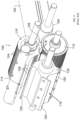
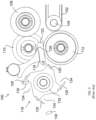
- FIGS. 4 through 6 represent isolated views of a size-reduction unit 30 configured to be installed on a size-reduction machine, as a nonlimiting example, the Model M6 TM represented in FIG. 1
- FIGS. 7 through 9 and 11 through 14 represent alternative configurations of components that can be utilized in the size-reduction unit 30.
- the unit 30 is particularly adapted to slice a product and then cut the resulting sliced product (strips) in a direction transverse to the cut that produced the strips (a "cross-cut") to achieve size reduction and produce a size-reduced product, as a nonlimiting example, dicing to produce a diced product.
- the size-reduction unit 30 and its benefits are not limited to such uses.
- the size-reduction unit 30 represented in FIGS. 4 through 6 is schematically represented as comprising a feed roll 32 ( FIG. 6 ), a circular cutter 34 comprising a row of circular knives 36, a feed drum 38, a stripper plate 40, and a cross-cutter 42 comprising multiple crosscut knives 44.
- Product 54 ( FIG. 6 ) is delivered to the unit 30 via a feed belt 46 driven by a drive roll 48, both of which are components of a conveyor unit 50.
- the feed roll 32, circular cutter 34, feed drum 38, cross-cutter 42, and drive roll 48 are individually mounted on spindles 52a-e and rotate about respective axes of rotation that are parallel to each other.
- the stripper plate 40 is mounted to a support bar 41 to maintain its orientation with the knives 36 of the circular cutter 34.
- the product 54 is delivered to the size-reduction unit 30 on the feed belt 46.
- the feed roll 32 is preferably spring-loaded and/or adjustable to enable products 54 of varying thicknesses to move through the unit 30 such that each product 54 is pinched between the feed roll 32 and drive roll 48 at the end of the feed belt 46 without being crushed.
- Each product 54 is forced into the circular cutter 34, whose circular (disk-shaped) knives 36 rotate through complementary grooves formed in the feed drum 38.
- the circular knives 36 are oriented approximately perpendicular to the rotational axis of the circular cutter 34, such that the circular cutter 34 cuts the product 54 into multiple parallel strips that are then removed from its circular knives 36 by a shear edge 56 of the stripper plate 40 before being delivered to the cross-cutter 42.
- the stripper plate 40 has a second shear edge 58 at which cross-cuts made by the knives 44 of the cross-cutter 42 occur to reduce the strips to produce, for example, cubes or rectangular-shaped size-reduced "diced" product of predetermined size.
- the shear edge 58 of the stripper plate 40 is in close proximity to the cross-cutter knives 44 to ensure complete dicing of strips delivered from the circular cutter 34 to the cross-cutter 42.
- the knives 44 of the cross-cutter 42 are not separate components attached to the cross-cutter 42, but instead are integrally formed features of the cross-cutter 42, though such a configuration is not required. Additionally, the knives 44 are not rectilinear in shape, nor are they oriented parallel to the rotational axis of the cross-cutter 42, or parallel to the shear edge 58, or perpendicular to the circular knives 36 of the circular cutter 34.
- the knives 44 have an arcuate shape that results in the cross-cutter 42 having a shape that will be referred to herein as "helical fluted.”
- the term “helical” refers to the geometric shape of each cutting edge 60 of the knives 44, and the term “fluted” refers to deep flutes 62 defined in the cross-cutter 42 between adjacent knives 44.
- the flutes 62 are not parallel to the rotational axis of the cross-cutter 42, but instead have helical shapes similar to the cutting edges 60 of the knives 44.
- the cutting edges 60 of the cross-cutter 42 Due to the helical shape of the cutting edge 60 of each knife 44, the cutting edges 60 of the cross-cutter 42 have a nonparallel relationship with the shear edge 58 of the stripper plate 40 to define what is referred to herein as a non-zero shear angle.
- the cutting edge 60 is at a constant radius from the axis of rotation of the cross-cutter 42, so that the spacial relationship between the cutting edge 60 and the shear edge 58 of the stripper plate 40 is the same along the entire length of the cutting edge 60 as the edge 60 progressively interacts with the shear edge 58.
- each knife 44 does not simultaneously engage the product 54, but instead the non-zero shear angle results in a shearing or slicing cut as opposed to the chopping cut associated with the cross-cutter 116 of FIGS. 1 through 3 .
- the product 54 is sliced progressively across its width rather than all at once, what may be referred to as a scissor action. Progressive slicing requires significantly less force from the crosscutter 42 than a chopping cut, imparts less force onto the product 54, and produces a more uniform cut.
- a diced product 64 ( FIG. 6 ) is impacted and captured by the flute 62 preceding the knife 44 that produced the product 64.
- the flute 62 accelerates the diced product 64 to the velocity at the location on the flute 62 that captures and cradles the product 64, after which the product 64 is propelled from the size-reduction unit 30 with centrifugal force as the cross-cutter 40 continues to rotate.
- the depths of the flutes 62 are greater than the depths of the channels 134 of the cross-cutter 116 of FIGS. 1 through 3 , depicted as being approximately 45% of the radius of the cross-cutter 116.
- the depths of the flutes 62 are preferably at least half of the radius of the cross-cutter 42, and in the embodiments shown the depths of the flutes 62 are approximately 65% of the radius of the cross-cutter 42.
- the deep fluted design of the cross-cutter 42 provides a smooth arcuate transition on each flute 62, which decreases the acceleration to which the diced product 64 is subjected after it is impacted and captured by the flute 62.
- the diced product 64 is stabilized and cradled in the flute 64 at a radial location of the cross-cutter 42 that is much closer to the axis of rotation of the cross-cutter 42, at which point the velocity of the product 64 is the same as the local velocity of the cross-cutter 42, so that the velocity of the product 64 is lower than if it were cradled at a radial location in the flute 64 farther from the axis of rotation.
- the combined effect of the helical and fluted features of the cross-cutter 42 is to reduce the cutting and impact loads on the original and diced products 54 and 64, resulting in less product damage as compared to the cross-cutter 116 of FIGS. 1 through 3 when operating at the same rotational speed. Consequently, the size-reduction unit 30 can be operated at higher speeds to increase product throughput, the result of which can be more product processed per hour with the same or less damage to the product.
- Such benefits are particularly significant when dicing soft or delicate products, as nonlimiting examples, cooked chicken, baked goods such brownies and bread, and granola bars.
- the flute angle defined herein as the angle between a radial of the cross-cutter 42 and a plane containing the surface of the flute 62 adjacent its adjoining cutting edge 62, is pertinent to the operation of the cross-cutter 42.
- the cross-cutter 42 shown in FIGS. 4 through 6 has a flute angle ( ⁇ ) of about 50 degrees. Flute angles significantly greater than 50 degrees, for example, about 60 degrees or more, have been observed to detain the diced product 64 in the flute 62 instead of being expelled, such that diced products 64 tend to collect in the flutes 62.
- the shear angle ( ⁇ ) of a cross-cutter knife 44 is defined herein as the angle between the cutting edge 60 of that knife 44 and a line that intersects the edge 60 and is parallel to the axis of rotation of the cross-cutter 42.
- the cross-cutter 42 shown in FIGS. 4 through 9 has a shear angle of about 10 degrees, though any shear angle other than zero degrees has the effect of decreasing cutting load.
- a clean and uniform cut is promoted by the entire cutting edge 60 being at a constant radius from the axis of rotation of the cross-cutter 42, such that a constant shear edge gap exits with the shear edge 58 of the stripper plate 40.
- the shear angle follows a helical curved path.
- the resulting cutting edges 60' of the cross-cutter 42 would not maintain a constant shear edge gap and would produce a lower quality cut.
- FIGS. 10 and 11 represent results of dynamic modeling performed to compare the elastic impacts and rigid body dynamics of a cross-cutter of the type represented in FIGS. 1 through 3 and a cross-cutter of the type represented in FIGS. 4 through 9 .
- FIG. 10 indicates that the simulated cross-cutter of FIGS. 1 through 3 would impact and accelerate a diced product over a span of about 4 milliseconds, corresponding to a very harsh impact and high acceleration.
- FIG. 11 indicates that the cross-cutter of FIGS. 4 through 9 more gradually accelerates a diced product over a much longer span of about 19 milliseconds, corresponding to a much lower impact on the product.
- FIGS. 1 through 3 Cooked chicken breasts were fed into a Model M6 TM dicer, which sliced the chicken with a circular cutter (for example, 4 in FIGS. 1 through 3 , and 34 in FIGS. 4 and 6 ) before undergoing cross-cutting with the installed cross-cutter to produce a diced chicken product.
- the prior art cross-cutter had a conventional zero shear angle (as defined in reference to FIGS. 1 through 3 ), whereas an experimental cross-cutter had a helical fluted configuration (as defined above in reference to FIGS.
- the diced chicken product was assessed on the basis of the yield of product too large to pass through a 11.11 mm (7/16 inch) screen.
- the Model M6 TM dicer produced a yield of, respectively, 68%, 77%, and 74%.
- the significantly improved yield exhibited by the experimental fluted cross-cutter was attributed to the reduced impact loads resulting from its fluted configuration, and the greater improved yield exhibited by the experimental helical fluted cross-cutter was attributed to the combined effects of reducing cutting loads and impact loads resulting from, respectively, its combined helical and fluted configurations.
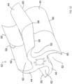
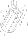
- FIGS. 12 , 13 , and 15 are isolated views of alternative embodiments of cross-cutters suitable for use in the size-reduction unit 30 of FIGS. 4 through 6 and a size-reduction machine of the type represented in FIG. 1 .
- FIG. 12 depicts a herringbone design in which the cutting edge 60 of each knife 44 of the cross-cutter 42 has a segment located in one of two opposite longitudinal halves of the crosscutter 42. The segments of each cutting edge 60 has opposite but equal helix angles (and shear angles), with each half of the cutting edge 60 retaining the helical and fluted design aspects of the cross-cutter 42 of FIGS. 4 through 9 .
- a herringbone cross-cutter 42 such as shown in FIG.
- FIG. 13 depicts a cross-cutter 42 whose knives 44 are replaceable, but otherwise retains the helical and fluted design aspects of the cross-cutter 42 of FIGS. 4 through 9 .
- the cross-cutter 42 of FIG. 13 comprises a rotor 42a, multiple knives 42b, a knife holder 42c for each knife 42b, and end caps 42d ( FIG. 14 ) for retaining the knife holders 42c in slots 42e formed in the rotor 42a.
- a benefit of the replaceable knives 44 is the ability to replace any or all of the knives 42b in the event that they become worn or damaged.
- FIG. 15 depicts a cross-cutter 42 that is also equipped with replaceable knives 44, and which is useful for understanding the context of the claimed invention.
- the cross-cutter 42 retains the fluted design aspect of the crosscutter 42 of FIGS. 4 through 9 , it does not retain its helical aspect.
- the cross-cutter of FIG. 15 comprises a rotor 42a, multiple knives 42b secured to the rotor 42a at a knife holder 42c, and end caps 42d (only one of which is shown).
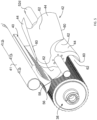
- FIGS. 16 through 18 are various views of an alternative embodiment of a conveyor unit 50 useful for understanding the context of the claimed invention and suitable for use with the size-reduction units of FIGS. 4 through 6 , cross-cutters of FIGS. 7 through 9 and 12 through 15 , and a size-reduction machine of the type represented in FIG. 1 .
- the belt 46 upstream of the entrance to the size-reduction unit 30 defines an infeed belt section 46a, and the belt 46 extends into the discharge chute 106 to further provide an outfeed belt section 46b at the outlet of the size-reduction unit 30.
- the entire belt 46 may be driven by a single drive roller 48, instead of two separate drive rollers that would be required to operate separate infeed and discharge conveyors.
- the conveyor unit 50 includes a reversing roll 66 so that the infeed and outfeed belt sections 46a and 46b of the belt 46 are staggered at different heights.
- a benefit of this design is that diced product 64 thrown from the cross-cutter 42 travels in the same direction as the direction of travel of the outfeed belt section 46a. The result is a lower velocity differential between the product 64 and the surface (belt section 46b) first encountered by the product 64 after leaving the size-reduction unit 30, thus minimizing impact forces as compared to landing against the static discharge chute 106.
- Another benefit is that small fines resulting from the dicing process cannot fall between the entrance and outlet of the size-reduction unit 30 because there is no gap between the infeed and outfeed sections 46a and 46b.
- Yet another benefit is that sticky diced product 64 is less likely to stick to the belt 46 as compared to being thrown against the static discharge chute 106.
- the invention encompasses additional or alternative embodiments in which one or more features or aspects of a particular embodiment could be eliminated or two or more features or aspects of different disclosed embodiments could be combined. Accordingly, it should be understood that the invention is not necessarily limited to any embodiment described herein or illustrated in the drawings. It should also be understood that the phraseology and terminology employed above are for the purpose of describing the illustrated embodiment, and do not necessarily serve as limitations to the scope of the invention. Therefore, the scope of the invention is to be limited only by the following claims.
Landscapes
- Life Sciences & Earth Sciences (AREA)
- Forests & Forestry (AREA)
- Engineering & Computer Science (AREA)
- Mechanical Engineering (AREA)
- Crushing And Pulverization Processes (AREA)
Claims (12)
- Größenreduzierungseinheit (30), aufweisend:ein kreisförmiges Schneidwerkzeug (34), das dazu angepasst und angeordnet ist, ein Produkt (54) in Streifen zu schneiden;ein rotierendes Querschneidwerkzeug (42), das dazu angepasst und angeordnet ist, die Streifen von dem kreisförmigen Schneidwerkzeug (34) aufzunehmen, wobei das Querschneidwerkzeug (42) Messer (44) aufweist, die jeweils eine bogenförmige Fläche aufweisen, die an einer angrenzenden Schneidkante (60) endet, wobei die Schneidkanten (60) dazu angepasst und angeordnet sind, die Streifen zu einem größenreduzierten Produkt (64) zuzuschneiden, wobei jede der Schneidkanten (60) bei einem konstanten Radius von einer Rotationsachse des Querschneidwerkzeugs (42) angeordnet ist und eine schraubenförmige geometrische Form aufweist, wobei die bogenförmige Fläche jedes der Messer (44) einen bogenförmigen Übergang zu einer radialen Position der bogenförmigen Fläche definiert, an der das größenreduzierte Produkt (64) stabilisiert und gehalten wird, wenn sich das Querschneidwerkzeug (42) dreht;eine Abstreiferplatte (40), die eine Scherkante (58) in der Nähe der Schneidkante (60) jedes der Messer (44) des Querschneidwerkzeugs (42) definiert, wenn die Schneidkanten (60) während der Rotation des Querschneidwerkzeugs (42) auf die Scherkante (58) treffen;wobei das Querschneidwerkzeug (42) eine schraubenförmige gekehlte Form aufweist, welche Hohlkehlen (62) zwischen benachbarten Paaren der Messer (44) aufweist, wobei jede der bogenförmigen Flächen einen Kehlwinkel (Θ) von mehr als 30 Grad bis weniger als 60 Grad an der Schneidkante (60) davon definiert, und wobei jede der Hohlkehlen (62) eine radiale Tiefe aufweist, die mindestens 50 % des konstanten Radius der Schneidkanten (60) beträgt;wobei die Hohlkehlen (62) schraubenförmige Formen aufweisen und nicht parallel zu einer Rotationsachse des Querschneidwerkzeugs (42) sind; undwobei jede der Schneidkanten (60) eine nichtparallele Beziehung zu der Scherkante (58) der Abstreiferplatte (40) aufweist, um einen von null verschiedenen Scherwinkel (Φ) zu definieren.
- Größenreduzierungseinheit (30) nach Anspruch 1, wobei die Gesamtheit jeder der Schneidkanten (60) bei dem konstanten Radius von der Rotationsachse des Querschneidwerkzeugs (42) angeordnet ist, so dass eine räumliche Beziehung zwischen der Schneidkante (60) und der Scherkante (58) der Abstreiferplatte (40) entlang der gesamten Länge der Schneidkante (60) dieselbe ist, während die Schneidkante (60) während der Rotation des Querschneidwerkzeugs (42) fortschreitend mit der Scherkante (58) zusammenwirkt.
- Größenreduzierungseinheit (30) nach Anspruch 1 oder 2, wobei die gesamte Schneidkante (60) jedes Messers (44) nicht gleichzeitig in das Produkt (54) eingreift, sondern stattdessen den Querschnitt in den Streifen über eine Scherenwirkung erzeugt.
- Größenreduzierungseinheit (30) nach einem der Ansprüche 1 bis 3, wobei die radialen Tiefen der Hohlkehlen (62) mindestens 65 % des konstanten Radius der Schneidkanten (60) betragen, und/oder wobei die durch die bogenförmigen Flächen definierten Kehlwinkel (8) jeweils 50 Grad bis weniger als 60 Grad betragen.
- Größenreduzierungseinheit (30) nach Anspruch 1, wobei das Querschneidwerkzeug (42) eine Fischgrätform aufweist, bei der jede Schneidkante (60) gegenüberliegende, aber gleiche Schrägungswinkel innerhalb gegenüberliegender Längshälften des Querschneidwerkzeugs (42) definiert.
- Größenreduzierungseinheit (30) nach einem der Ansprüche 1 bis 5, wobei die Messer (44) des Querschneidwerkzeugs (42) einstückig ausgebildete Merkmale des Querschneidwerkzeugs (42) sind, und/oder wobei die Messer (44) des Querschneidwerkzeugs (42) separate Komponenten (42b) sind, die an einem Rotor (42a) des Querschneidwerkzeugs (42) angebracht sind.
- Größenreduzierungseinheit (30) nach einem der Ansprüche 1 bis 6, ferner aufweisend eine Fördereinheit (50), die ein Zuführband zum Fördern des Produkts (54) zu dem kreisförmigen Schneidwerkzeug (34) umfasst.
- Größenreduzierungseinheit (30) nach Anspruch 7, wobei die Fördereinheit (50) ein Band (46) umfasst, das einen Zuführbandabschnitt (46a), der das Produkt (54) zu dem kreisförmigen Schneidwerkzeug (34) liefert, und einen Abführbandabschnitt (46b) aufweist, der das größenreduzierte Produkt (64) von dem Querschneidwerkzeug (42) aufnimmt, wobei der Abführbandabschnitt (46b) eine Bewegungsrichtung weg von dem Querschneidwerkzeug (42) aufweist, wobei das Band (46) vorzugsweise durch eine einzelne Antriebsrolle (48) angetrieben wird.
- Größenreduzierungseinheit (30) nach Anspruch 8, wobei das Querschneidwerkzeug (42) dazu angepasst und eingerichtet ist, das größenreduzierte Produkt (64) in die gleiche Richtung wie die Bewegungsrichtung des Abführbandabschnitts (46b) zu werfen.
- Größenreduzierungsmaschine, aufweisend die Größenreduzierungseinheit (30) nach einem der Ansprüche 1 bis 9, wobei die Maschine vorzugsweise ein Würfelschneider ist.
- Verfahren zum Verwenden der Maschine nach Anspruch 10, wobei das Verfahren umfasst:Zuführen des Produkts (54) zu dem kreisförmigen Schneidwerkzeug (34), um die Streifen herzustellen;Drehen des Querschneidwerkzeugs (42), um die Streifen mit den Messern (44) des Querschneidwerkzeugs (42) zu würfeln und ein gewürfeltes Produkt (64) herzustellen;Einfangen des gewürfelten Produkts (64) in den Hohlkehlen (62) des Querschneidwerkzeugs (42), während sich das Querschneidwerkzeug (42) dreht; und dannAusstoßen des gewürfelten Produkts (64) aus den Hohlkehlen (62) des Querschneidwerkzeugs (42), während sich das Querschneidwerkzeug (42) weiter dreht.
- Verfahren nach Anspruch 11, ferner aufweisend eine Fördereinheit (50), die einen Zuführbandabschnitt (46a), der das Produkt (54) zu dem kreisförmigen Schneidwerkzeug (34) liefert, und einen Abführbandabschnitt (46b) aufweist, der das gewürfelte Produkt (64) von dem Querschneidwerkzeug (42) aufnimmt, wobei der Abführbandabschnitt (46b) eine Bewegungsrichtung weg von dem Querschneidwerkzeug (42) aufweist, wobei das Querschneidwerkzeug (42) vorzugsweise das gewürfelte Produkt (64) in die gleiche Richtung wie die Bewegungsrichtung des Abführbandabschnitts (46b) wirft.
Applications Claiming Priority (2)
| Application Number | Priority Date | Filing Date | Title |
|---|---|---|---|
| US201762519227P | 2017-06-14 | 2017-06-14 | |
| PCT/US2018/037499 WO2018232091A1 (en) | 2017-06-14 | 2018-06-14 | Size-reduction machine and size-reduction unit therefor |
Publications (3)
| Publication Number | Publication Date |
|---|---|
| EP3638468A1 EP3638468A1 (de) | 2020-04-22 |
| EP3638468A4 EP3638468A4 (de) | 2021-03-31 |
| EP3638468B1 true EP3638468B1 (de) | 2024-12-18 |
Family
ID=64656100
Family Applications (1)
| Application Number | Title | Priority Date | Filing Date |
|---|---|---|---|
| EP18816863.7A Active EP3638468B1 (de) | 2017-06-14 | 2018-06-14 | Verkleinerungsmaschine und verkleinerungseinheit dafür |
Country Status (7)
| Country | Link |
|---|---|
| US (1) | US10933550B2 (de) |
| EP (1) | EP3638468B1 (de) |
| AU (1) | AU2018283050B2 (de) |
| CA (1) | CA3066248C (de) |
| HU (1) | HUE070520T2 (de) |
| MX (1) | MX2019014918A (de) |
| WO (1) | WO2018232091A1 (de) |
Families Citing this family (12)
| Publication number | Priority date | Publication date | Assignee | Title |
|---|---|---|---|---|
| US11254024B2 (en) | 2013-06-12 | 2022-02-22 | The Procter & Gamble Company | Method of perforating a nonlinear line of weakness |
| WO2014201072A1 (en) | 2013-06-12 | 2014-12-18 | The Procter & Gamble Company | A nonlinear line of weakness formed by a perforating apparatus |
| DE102014117848B3 (de) * | 2014-12-04 | 2016-05-19 | Hochland Se | Längsschneiden eines Bandes einer weichen Lebensmittelmasse |
| WO2016148900A1 (en) | 2015-03-17 | 2016-09-22 | The Procter & Gamble Company | Apparatus for perforating a nonlinear line of weakness |
| WO2016148894A1 (en) | 2015-03-17 | 2016-09-22 | The Procter & Gamble Company | Method for perforating a nonlinear line of weakness |
| WO2016148899A1 (en) | 2015-03-17 | 2016-09-22 | The Procter & Gamble Company | Apparatus for perforating a web material |
| CA3072516A1 (en) | 2017-09-11 | 2019-03-14 | The Procter & Gamble Company | Sanitary tissue product with a shaped line of weakness |
| US11806890B2 (en) | 2017-09-11 | 2023-11-07 | The Procter & Gamble Company | Perforating apparatus and method for manufacturing a shaped line of weakness |
| US11806889B2 (en) | 2017-09-11 | 2023-11-07 | The Procter & Gamble Company | Perforating apparatus and method for manufacturing a shaped line of weakness |
| GB2580677B (en) | 2019-01-23 | 2021-08-18 | Donaghy Eng Ltd | A food processing apparatus |
| GB2592542B (en) * | 2019-01-23 | 2023-06-07 | Donaghy Eng Ltd | A food processing apparatus |
| CN114851289B (zh) * | 2022-06-13 | 2024-04-26 | 湖南苗乡节能环保科技有限公司 | 一种固体生物质燃料自动化生产系统 |
Citations (1)
| Publication number | Priority date | Publication date | Assignee | Title |
|---|---|---|---|---|
| EP0363220B1 (de) * | 1988-10-07 | 1993-08-11 | Urschel Laboratories, Inc. | Würfelschneidvorrichtung |
Family Cites Families (16)
| Publication number | Priority date | Publication date | Assignee | Title |
|---|---|---|---|---|
| US3777600A (en) * | 1971-10-13 | 1973-12-11 | Marlen Res Corp | Machine for and method of severing meat slabs |
| US3837249A (en) * | 1971-10-13 | 1974-09-24 | Marlen Res Corp | Machine for severing meat slabs |
| US4613087A (en) * | 1983-06-13 | 1986-09-23 | Uniroyal Tire Company, Inc. | Scrap tire cutting apparatus |
| DE3514389A1 (de) * | 1985-04-20 | 1986-10-23 | E.C.H. Will (Gmbh & Co), 2000 Hamburg | Verfahren und vorrichtung zur lagegerechten positionierung von markierungen auf materialbahnabschnitten |
| US4664006A (en) * | 1985-09-27 | 1987-05-12 | Swm Corporation | Rotary cutter apparatus |
| US5129299A (en) * | 1988-10-07 | 1992-07-14 | Urschel Laboratories Incorporated | Dicing machine |
| US6314849B1 (en) * | 1997-09-19 | 2001-11-13 | Urschel Laboratories Inc. | Dicing machine with improved cutting squareness |
| US6938844B2 (en) | 2001-12-26 | 2005-09-06 | Charles A. Castronovo | Zero-clearance cutting systems |
| US7237586B2 (en) * | 2002-10-22 | 2007-07-03 | Moulder Services, Inc. | Rotatable cutting tool |
| US20060067797A1 (en) | 2004-09-28 | 2006-03-30 | Calamia Guy A | End mill |
| US8006470B2 (en) * | 2005-10-11 | 2011-08-30 | Agco Corporation | Crop harvester having metal conditioner rolls with herringbone rib pattern |
| US20070277682A1 (en) | 2006-06-06 | 2007-12-06 | Yan Kwong Wong | Multi-function juicer |
| US20100209201A1 (en) * | 2009-02-17 | 2010-08-19 | Kennametal Inc. | Rotary cutting tool with wave pattern |
| US8967505B2 (en) * | 2011-11-11 | 2015-03-03 | Tyson Foods, Inc. | Method and apparatus for shredding meat |
| US20150245925A1 (en) * | 2014-02-28 | 2015-09-03 | Bacterin International, Inc. | Cutting assembly and method of use |
| US10328596B2 (en) * | 2015-12-04 | 2019-06-25 | Urschel Laboratories, Inc. | Stripper plates, dicing machines that utilize stripper plates, and methods of use |
-
2018
- 2018-06-14 WO PCT/US2018/037499 patent/WO2018232091A1/en not_active Ceased
- 2018-06-14 HU HUE18816863A patent/HUE070520T2/hu unknown
- 2018-06-14 US US16/008,409 patent/US10933550B2/en active Active
- 2018-06-14 EP EP18816863.7A patent/EP3638468B1/de active Active
- 2018-06-14 AU AU2018283050A patent/AU2018283050B2/en active Active
- 2018-06-14 MX MX2019014918A patent/MX2019014918A/es unknown
- 2018-06-14 CA CA3066248A patent/CA3066248C/en active Active
Patent Citations (1)
| Publication number | Priority date | Publication date | Assignee | Title |
|---|---|---|---|---|
| EP0363220B1 (de) * | 1988-10-07 | 1993-08-11 | Urschel Laboratories, Inc. | Würfelschneidvorrichtung |
Also Published As
| Publication number | Publication date |
|---|---|
| WO2018232091A1 (en) | 2018-12-20 |
| AU2018283050B2 (en) | 2020-12-24 |
| CA3066248C (en) | 2021-12-07 |
| EP3638468A4 (de) | 2021-03-31 |
| CA3066248A1 (en) | 2018-12-20 |
| MX2019014918A (es) | 2020-02-07 |
| HUE070520T2 (hu) | 2025-06-28 |
| US20180361606A1 (en) | 2018-12-20 |
| US10933550B2 (en) | 2021-03-02 |
| AU2018283050A1 (en) | 2019-12-12 |
| EP3638468A1 (de) | 2020-04-22 |
Similar Documents
| Publication | Publication Date | Title |
|---|---|---|
| EP3638468B1 (de) | Verkleinerungsmaschine und verkleinerungseinheit dafür | |
| EP3307499B1 (de) | Maschinen und verfahren zum schneiden von produkten | |
| US5129299A (en) | Dicing machine | |
| AU2011200462B2 (en) | Apparatus For Cutting Potatoes or Similar Vegetables | |
| US7658133B2 (en) | Apparatus for cutting food product | |
| DE60114771T2 (de) | Verfahren und vorrichtung zum zerkleinern blockmaterial | |
| CA3041296C (en) | Size-reduction machines, feed units therefor, and methods of use | |
| US9808952B2 (en) | Sheet material cutting apparatus, and associated method | |
| US10442102B2 (en) | Machines and methods for cutting products to produce reduced-size products therefrom | |
| EP1377415A1 (de) | Laufrad für rotierenden scheibenschneidmaschine | |
| CA1318574C (en) | Dicing machine | |
| EP3288730B1 (de) | Vorrichtung und verfahren zum schneiden von produkten zur herstellung von produkten mit reduzierter grösse daraus | |
| CN109259301B (zh) | 用于切割棒形制品的设备以及具有这种设备的机器 | |
| AU2019410699B2 (en) | A food processing device and a method of processing food | |
| US7201339B2 (en) | Method and apparatus for producing wood shavings | |
| US10328596B2 (en) | Stripper plates, dicing machines that utilize stripper plates, and methods of use | |
| US10513044B1 (en) | Bacon portioner/trimmer | |
| CA2475458C (en) | Method and apparatus for producing wood shavings | |
| CN204997743U (zh) | 一种叶菜切丁机 | |
| CA3124490C (en) | A food processing device and a method of processing food | |
| PL247751B1 (pl) | Maszyna do cięcia w kostkę mrożonych artykułów spożywczych | |
| CN105034057A (zh) | 一种叶菜切丁机 |
Legal Events
| Date | Code | Title | Description |
|---|---|---|---|
| STAA | Information on the status of an ep patent application or granted ep patent |
Free format text: STATUS: THE INTERNATIONAL PUBLICATION HAS BEEN MADE |
|
| PUAI | Public reference made under article 153(3) epc to a published international application that has entered the european phase |
Free format text: ORIGINAL CODE: 0009012 |
|
| STAA | Information on the status of an ep patent application or granted ep patent |
Free format text: STATUS: REQUEST FOR EXAMINATION WAS MADE |
|
| 17P | Request for examination filed |
Effective date: 20191122 |
|
| AK | Designated contracting states |
Kind code of ref document: A1 Designated state(s): AL AT BE BG CH CY CZ DE DK EE ES FI FR GB GR HR HU IE IS IT LI LT LU LV MC MK MT NL NO PL PT RO RS SE SI SK SM TR |
|
| AX | Request for extension of the european patent |
Extension state: BA ME |
|
| DAV | Request for validation of the european patent (deleted) | ||
| DAX | Request for extension of the european patent (deleted) | ||
| A4 | Supplementary search report drawn up and despatched |
Effective date: 20210226 |
|
| RIC1 | Information provided on ipc code assigned before grant |
Ipc: B26D 3/24 20060101ALI20210222BHEP Ipc: B26D 1/36 20060101AFI20210222BHEP Ipc: B26D 7/26 20060101ALI20210222BHEP Ipc: B26D 1/00 20060101ALI20210222BHEP Ipc: B26D 7/06 20060101ALI20210222BHEP |
|
| STAA | Information on the status of an ep patent application or granted ep patent |
Free format text: STATUS: EXAMINATION IS IN PROGRESS |
|
| 17Q | First examination report despatched |
Effective date: 20230120 |
|
| GRAP | Despatch of communication of intention to grant a patent |
Free format text: ORIGINAL CODE: EPIDOSNIGR1 |
|
| STAA | Information on the status of an ep patent application or granted ep patent |
Free format text: STATUS: GRANT OF PATENT IS INTENDED |
|
| INTG | Intention to grant announced |
Effective date: 20240709 |
|
| P01 | Opt-out of the competence of the unified patent court (upc) registered |
Free format text: CASE NUMBER: APP_42754/2024 Effective date: 20240719 |
|
| GRAS | Grant fee paid |
Free format text: ORIGINAL CODE: EPIDOSNIGR3 |
|
| GRAA | (expected) grant |
Free format text: ORIGINAL CODE: 0009210 |
|
| STAA | Information on the status of an ep patent application or granted ep patent |
Free format text: STATUS: THE PATENT HAS BEEN GRANTED |
|
| AK | Designated contracting states |
Kind code of ref document: B1 Designated state(s): AL AT BE BG CH CY CZ DE DK EE ES FI FR GB GR HR HU IE IS IT LI LT LU LV MC MK MT NL NO PL PT RO RS SE SI SK SM TR |
|
| REG | Reference to a national code |
Ref country code: GB Ref legal event code: FG4D |
|
| REG | Reference to a national code |
Ref country code: CH Ref legal event code: EP |
|
| REG | Reference to a national code |
Ref country code: DE Ref legal event code: R096 Ref document number: 602018077779 Country of ref document: DE |
|
| REG | Reference to a national code |
Ref country code: IE Ref legal event code: FG4D |
|
| REG | Reference to a national code |
Ref country code: NL Ref legal event code: FP |
|
| REG | Reference to a national code |
Ref country code: LT Ref legal event code: MG9D |
|
| PG25 | Lapsed in a contracting state [announced via postgrant information from national office to epo] |
Ref country code: HR Free format text: LAPSE BECAUSE OF FAILURE TO SUBMIT A TRANSLATION OF THE DESCRIPTION OR TO PAY THE FEE WITHIN THE PRESCRIBED TIME-LIMIT Effective date: 20241218 |
|
| PG25 | Lapsed in a contracting state [announced via postgrant information from national office to epo] |
Ref country code: FI Free format text: LAPSE BECAUSE OF FAILURE TO SUBMIT A TRANSLATION OF THE DESCRIPTION OR TO PAY THE FEE WITHIN THE PRESCRIBED TIME-LIMIT Effective date: 20241218 |
|
| PG25 | Lapsed in a contracting state [announced via postgrant information from national office to epo] |
Ref country code: BG Free format text: LAPSE BECAUSE OF FAILURE TO SUBMIT A TRANSLATION OF THE DESCRIPTION OR TO PAY THE FEE WITHIN THE PRESCRIBED TIME-LIMIT Effective date: 20241218 |
|
| PG25 | Lapsed in a contracting state [announced via postgrant information from national office to epo] |
Ref country code: NO Free format text: LAPSE BECAUSE OF FAILURE TO SUBMIT A TRANSLATION OF THE DESCRIPTION OR TO PAY THE FEE WITHIN THE PRESCRIBED TIME-LIMIT Effective date: 20250318 |
|
| PG25 | Lapsed in a contracting state [announced via postgrant information from national office to epo] |
Ref country code: LV Free format text: LAPSE BECAUSE OF FAILURE TO SUBMIT A TRANSLATION OF THE DESCRIPTION OR TO PAY THE FEE WITHIN THE PRESCRIBED TIME-LIMIT Effective date: 20241218 Ref country code: GR Free format text: LAPSE BECAUSE OF FAILURE TO SUBMIT A TRANSLATION OF THE DESCRIPTION OR TO PAY THE FEE WITHIN THE PRESCRIBED TIME-LIMIT Effective date: 20250319 |
|
| PG25 | Lapsed in a contracting state [announced via postgrant information from national office to epo] |
Ref country code: RS Free format text: LAPSE BECAUSE OF FAILURE TO SUBMIT A TRANSLATION OF THE DESCRIPTION OR TO PAY THE FEE WITHIN THE PRESCRIBED TIME-LIMIT Effective date: 20250318 |
|
| REG | Reference to a national code |
Ref country code: HU Ref legal event code: AG4A Ref document number: E070520 Country of ref document: HU |
|
| PG25 | Lapsed in a contracting state [announced via postgrant information from national office to epo] |
Ref country code: SM Free format text: LAPSE BECAUSE OF FAILURE TO SUBMIT A TRANSLATION OF THE DESCRIPTION OR TO PAY THE FEE WITHIN THE PRESCRIBED TIME-LIMIT Effective date: 20241218 |
|
| PG25 | Lapsed in a contracting state [announced via postgrant information from national office to epo] |
Ref country code: PL Free format text: LAPSE BECAUSE OF FAILURE TO SUBMIT A TRANSLATION OF THE DESCRIPTION OR TO PAY THE FEE WITHIN THE PRESCRIBED TIME-LIMIT Effective date: 20241218 |
|
| PGFP | Annual fee paid to national office [announced via postgrant information from national office to epo] |
Ref country code: DE Payment date: 20250605 Year of fee payment: 8 |
|
| PG25 | Lapsed in a contracting state [announced via postgrant information from national office to epo] |
Ref country code: ES Free format text: LAPSE BECAUSE OF FAILURE TO SUBMIT A TRANSLATION OF THE DESCRIPTION OR TO PAY THE FEE WITHIN THE PRESCRIBED TIME-LIMIT Effective date: 20241218 |
|
| PGFP | Annual fee paid to national office [announced via postgrant information from national office to epo] |
Ref country code: GB Payment date: 20250627 Year of fee payment: 8 |
|
| PG25 | Lapsed in a contracting state [announced via postgrant information from national office to epo] |
Ref country code: IS Free format text: LAPSE BECAUSE OF FAILURE TO SUBMIT A TRANSLATION OF THE DESCRIPTION OR TO PAY THE FEE WITHIN THE PRESCRIBED TIME-LIMIT Effective date: 20250418 |
|
| PGFP | Annual fee paid to national office [announced via postgrant information from national office to epo] |
Ref country code: NL Payment date: 20250605 Year of fee payment: 8 Ref country code: BE Payment date: 20250605 Year of fee payment: 8 |
|
| PG25 | Lapsed in a contracting state [announced via postgrant information from national office to epo] |
Ref country code: PT Free format text: LAPSE BECAUSE OF FAILURE TO SUBMIT A TRANSLATION OF THE DESCRIPTION OR TO PAY THE FEE WITHIN THE PRESCRIBED TIME-LIMIT Effective date: 20250421 |
|
| PG25 | Lapsed in a contracting state [announced via postgrant information from national office to epo] |
Ref country code: EE Free format text: LAPSE BECAUSE OF FAILURE TO SUBMIT A TRANSLATION OF THE DESCRIPTION OR TO PAY THE FEE WITHIN THE PRESCRIBED TIME-LIMIT Effective date: 20241218 |
|
| PGFP | Annual fee paid to national office [announced via postgrant information from national office to epo] |
Ref country code: HU Payment date: 20250606 Year of fee payment: 8 Ref country code: FR Payment date: 20250612 Year of fee payment: 8 |
|
| PG25 | Lapsed in a contracting state [announced via postgrant information from national office to epo] |
Ref country code: RO Free format text: LAPSE BECAUSE OF FAILURE TO SUBMIT A TRANSLATION OF THE DESCRIPTION OR TO PAY THE FEE WITHIN THE PRESCRIBED TIME-LIMIT Effective date: 20241218 |
|
| PGFP | Annual fee paid to national office [announced via postgrant information from national office to epo] |
Ref country code: AT Payment date: 20250605 Year of fee payment: 8 |
|
| PG25 | Lapsed in a contracting state [announced via postgrant information from national office to epo] |
Ref country code: SK Free format text: LAPSE BECAUSE OF FAILURE TO SUBMIT A TRANSLATION OF THE DESCRIPTION OR TO PAY THE FEE WITHIN THE PRESCRIBED TIME-LIMIT Effective date: 20241218 |
|
| PG25 | Lapsed in a contracting state [announced via postgrant information from national office to epo] |
Ref country code: CZ Free format text: LAPSE BECAUSE OF FAILURE TO SUBMIT A TRANSLATION OF THE DESCRIPTION OR TO PAY THE FEE WITHIN THE PRESCRIBED TIME-LIMIT Effective date: 20241218 |
|
| PG25 | Lapsed in a contracting state [announced via postgrant information from national office to epo] |
Ref country code: IT Free format text: LAPSE BECAUSE OF FAILURE TO SUBMIT A TRANSLATION OF THE DESCRIPTION OR TO PAY THE FEE WITHIN THE PRESCRIBED TIME-LIMIT Effective date: 20241218 |
|
| PG25 | Lapsed in a contracting state [announced via postgrant information from national office to epo] |
Ref country code: SE Free format text: LAPSE BECAUSE OF FAILURE TO SUBMIT A TRANSLATION OF THE DESCRIPTION OR TO PAY THE FEE WITHIN THE PRESCRIBED TIME-LIMIT Effective date: 20241218 |
|
| REG | Reference to a national code |
Ref country code: DE Ref legal event code: R097 Ref document number: 602018077779 Country of ref document: DE |
|
| PG25 | Lapsed in a contracting state [announced via postgrant information from national office to epo] |
Ref country code: DK Free format text: LAPSE BECAUSE OF FAILURE TO SUBMIT A TRANSLATION OF THE DESCRIPTION OR TO PAY THE FEE WITHIN THE PRESCRIBED TIME-LIMIT Effective date: 20241218 |
|
| PGFP | Annual fee paid to national office [announced via postgrant information from national office to epo] |
Ref country code: CH Payment date: 20250701 Year of fee payment: 8 |
|
| PLBE | No opposition filed within time limit |
Free format text: ORIGINAL CODE: 0009261 |
|
| STAA | Information on the status of an ep patent application or granted ep patent |
Free format text: STATUS: NO OPPOSITION FILED WITHIN TIME LIMIT |
|
| 26N | No opposition filed |
Effective date: 20250919 |
|
| PG25 | Lapsed in a contracting state [announced via postgrant information from national office to epo] |
Ref country code: MC Free format text: LAPSE BECAUSE OF FAILURE TO SUBMIT A TRANSLATION OF THE DESCRIPTION OR TO PAY THE FEE WITHIN THE PRESCRIBED TIME-LIMIT Effective date: 20241218 |
|
| PG25 | Lapsed in a contracting state [announced via postgrant information from national office to epo] |
Ref country code: LU Free format text: LAPSE BECAUSE OF NON-PAYMENT OF DUE FEES Effective date: 20250614 |
|
| REG | Reference to a national code |
Ref country code: AT Ref legal event code: UEP Ref document number: 1751906 Country of ref document: AT Kind code of ref document: T Effective date: 20241218 |
|
| PG25 | Lapsed in a contracting state [announced via postgrant information from national office to epo] |
Ref country code: IE Free format text: LAPSE BECAUSE OF NON-PAYMENT OF DUE FEES Effective date: 20250614 |