EP3638998B1 - Module capteur de pression pour des applications à haute pression de service - Google Patents
Module capteur de pression pour des applications à haute pression de service Download PDFInfo
- Publication number
- EP3638998B1 EP3638998B1 EP18817163.1A EP18817163A EP3638998B1 EP 3638998 B1 EP3638998 B1 EP 3638998B1 EP 18817163 A EP18817163 A EP 18817163A EP 3638998 B1 EP3638998 B1 EP 3638998B1
- Authority
- EP
- European Patent Office
- Prior art keywords
- differential pressure
- pressure sensor
- sensor module
- module
- electronics
- Prior art date
- Legal status (The legal status is an assumption and is not a legal conclusion. Google has not performed a legal analysis and makes no representation as to the accuracy of the status listed.)
- Active
Links
Images




Classifications
-
- G—PHYSICS
- G01—MEASURING; TESTING
- G01L—MEASURING FORCE, STRESS, TORQUE, WORK, MECHANICAL POWER, MECHANICAL EFFICIENCY, OR FLUID PRESSURE
- G01L19/00—Details of, or accessories for, apparatus for measuring steady or quasi-steady pressure of a fluent medium insofar as such details or accessories are not special to particular types of pressure gauges
- G01L19/0092—Pressure sensor associated with other sensors, e.g. for measuring acceleration or temperature
-
- G—PHYSICS
- G01—MEASURING; TESTING
- G01L—MEASURING FORCE, STRESS, TORQUE, WORK, MECHANICAL POWER, MECHANICAL EFFICIENCY, OR FLUID PRESSURE
- G01L19/00—Details of, or accessories for, apparatus for measuring steady or quasi-steady pressure of a fluent medium insofar as such details or accessories are not special to particular types of pressure gauges
- G01L19/06—Means for preventing overload or deleterious influence of the measured medium on the measuring device or vice versa
- G01L19/0618—Overload protection
-
- G—PHYSICS
- G01—MEASURING; TESTING
- G01L—MEASURING FORCE, STRESS, TORQUE, WORK, MECHANICAL POWER, MECHANICAL EFFICIENCY, OR FLUID PRESSURE
- G01L13/00—Devices or apparatus for measuring differences of two or more fluid pressure values
-
- G—PHYSICS
- G01—MEASURING; TESTING
- G01L—MEASURING FORCE, STRESS, TORQUE, WORK, MECHANICAL POWER, MECHANICAL EFFICIENCY, OR FLUID PRESSURE
- G01L13/00—Devices or apparatus for measuring differences of two or more fluid pressure values
- G01L13/02—Devices or apparatus for measuring differences of two or more fluid pressure values using elastically-deformable members or pistons as sensing elements
- G01L13/025—Devices or apparatus for measuring differences of two or more fluid pressure values using elastically-deformable members or pistons as sensing elements using diaphragms
-
- G—PHYSICS
- G01—MEASURING; TESTING
- G01L—MEASURING FORCE, STRESS, TORQUE, WORK, MECHANICAL POWER, MECHANICAL EFFICIENCY, OR FLUID PRESSURE
- G01L13/00—Devices or apparatus for measuring differences of two or more fluid pressure values
- G01L13/02—Devices or apparatus for measuring differences of two or more fluid pressure values using elastically-deformable members or pistons as sensing elements
- G01L13/025—Devices or apparatus for measuring differences of two or more fluid pressure values using elastically-deformable members or pistons as sensing elements using diaphragms
- G01L13/026—Devices or apparatus for measuring differences of two or more fluid pressure values using elastically-deformable members or pistons as sensing elements using diaphragms involving double diaphragm
-
- G—PHYSICS
- G01—MEASURING; TESTING
- G01L—MEASURING FORCE, STRESS, TORQUE, WORK, MECHANICAL POWER, MECHANICAL EFFICIENCY, OR FLUID PRESSURE
- G01L19/00—Details of, or accessories for, apparatus for measuring steady or quasi-steady pressure of a fluent medium insofar as such details or accessories are not special to particular types of pressure gauges
- G01L19/0007—Fluidic connecting means
- G01L19/0046—Fluidic connecting means using isolation membranes
-
- G—PHYSICS
- G01—MEASURING; TESTING
- G01L—MEASURING FORCE, STRESS, TORQUE, WORK, MECHANICAL POWER, MECHANICAL EFFICIENCY, OR FLUID PRESSURE
- G01L19/00—Details of, or accessories for, apparatus for measuring steady or quasi-steady pressure of a fluent medium insofar as such details or accessories are not special to particular types of pressure gauges
- G01L19/04—Means for compensating for effects of changes of temperature, i.e. other than electric compensation
-
- G—PHYSICS
- G01—MEASURING; TESTING
- G01L—MEASURING FORCE, STRESS, TORQUE, WORK, MECHANICAL POWER, MECHANICAL EFFICIENCY, OR FLUID PRESSURE
- G01L9/00—Measuring steady of quasi-steady pressure of fluid or fluent solid material by electric or magnetic pressure-sensitive elements; Transmitting or indicating the displacement of mechanical pressure-sensitive elements, used to measure the steady or quasi-steady pressure of a fluid or fluent solid material, by electric or magnetic means
- G01L9/0041—Transmitting or indicating the displacement of flexible diaphragms
- G01L9/0042—Constructional details associated with semiconductive diaphragm sensors, e.g. etching, or constructional details of non-semiconductive diaphragms
-
- G—PHYSICS
- G01—MEASURING; TESTING
- G01L—MEASURING FORCE, STRESS, TORQUE, WORK, MECHANICAL POWER, MECHANICAL EFFICIENCY, OR FLUID PRESSURE
- G01L9/00—Measuring steady of quasi-steady pressure of fluid or fluent solid material by electric or magnetic pressure-sensitive elements; Transmitting or indicating the displacement of mechanical pressure-sensitive elements, used to measure the steady or quasi-steady pressure of a fluid or fluent solid material, by electric or magnetic means
- G01L9/0041—Transmitting or indicating the displacement of flexible diaphragms
- G01L9/0042—Constructional details associated with semiconductive diaphragm sensors, e.g. etching, or constructional details of non-semiconductive diaphragms
- G01L9/0044—Constructional details of non-semiconductive diaphragms
-
- G—PHYSICS
- G01—MEASURING; TESTING
- G01L—MEASURING FORCE, STRESS, TORQUE, WORK, MECHANICAL POWER, MECHANICAL EFFICIENCY, OR FLUID PRESSURE
- G01L9/00—Measuring steady of quasi-steady pressure of fluid or fluent solid material by electric or magnetic pressure-sensitive elements; Transmitting or indicating the displacement of mechanical pressure-sensitive elements, used to measure the steady or quasi-steady pressure of a fluid or fluent solid material, by electric or magnetic means
- G01L9/0041—Transmitting or indicating the displacement of flexible diaphragms
- G01L9/0042—Constructional details associated with semiconductive diaphragm sensors, e.g. etching, or constructional details of non-semiconductive diaphragms
- G01L9/0048—Details about the mounting of the diaphragm to its support or about the diaphragm edges, e.g. notches, round shapes for stress relief
Definitions
- Pressure transmitters are commonly used in industrial processes to measure pressures in various industrial process fluids, such as slurries, liquids, vapors and gases of chemical, pulp, petroleum, gas, pharmaceutical, food and other fluid-type processing plants.
- Differential pressure transmitters generally include a pair of process fluid pressure inputs which are operably coupled to a differential pressure sensor (within the differential pressure transmitter) that responds to the difference in pressure between the two inputs.
- Differential pressure transmitters typically include a pair of isolator diaphragms that are positioned in the process fluid inlets and isolate the differential pressure sensor from the harsh fluids being sensed. Pressure is transferred from the process fluid to the differential pressure sensor through a substantially incompressible fill fluid carried in a passageway extending from each isolator diaphragm to the differential pressure sensor.
- process fluid flow measurement devices i.e., flowmeters
- process fluid flow measurement devices employ a variety of different technologies (venturi, orifice plate, v-cone, etc.) that utilize differential pressure measurements as a core technology in order to enable the flow measurement.
- the differential pressure measurements are typically in the range of 0-75 psi.
- Differential pressure sensor modules are disclosed e.g. in US2006/162460 A1 , WO2009/038979 A1 , US2015/082903 A1 , and US4218925 A .
- Providing a pressure sensor module adapted for high working pressure applications, such as sub-sea environments, without requiring extensive modification or expense will facilitate the more widespread adaption and utilization of differential pressure sensors in such applications and will improve the processes that employ such technology.
- a differential pressure sensor module according to claim 1 is disclosed. Advantageous features are disclosed in the dependent claims.
- FIG. 1 is a diagrammatic view of a coplanar differential pressure sensor module 100 with which embodiments of the present invention are particularly applicable.
- Sensor module 100 is couplable to electronics enclosure 102 and can measure differential pressure introduced at a pair of process fluid pressure inlets 104, 106.
- Electronics enclosure 102 may contain suitable electronics circuitry to communicate process fluid pressure obtained from module 100 to another device or a control room.
- Base portion 108 of differential pressure sensor module 100 may, in some instances, be constructed from a material that is suitable for direct immersion in salt water.
- One example of such a material is alloy C276 available from Haynes International Inc., of Kokomo, Indiana under the trade designation Hastelloy C276.
- base portion 108 may include an annular ring 109 that is sized and shaped to receive a sub-sea rated housing or endcap and be welded thereto. In this manner, portion 108 may, in some instances, be formed of the same material as that of existing sub-sea housings, such as alloy C276.
- Coplanar differential pressure sensor module 100 also includes a sidewall 110 coupled to base portion 108, which sidewall 110 couples to cap 112.
- An electrical feedthrough connector 114 is couplable to electronics enclosure 102 and includes conductors to provide power to module 100 as well as bidirectional communication. In some instances, module 100 may communicate over the same conductors through which it is powered.
- FIG. 2 is a diagrammatic view of coplanar differential pressure sensor module 100 (illustrated in FIG. 1 ) adapted for direct immersion in sea water.
- the upper portion of coplanar differential pressure sensor module 100, proximate electrical connection point 115, is covered with a high pressure bearing endcap 120 that is constructed from a material that is suitable for direct immersion in sea water, such as alloy C276.
- Endcap 120 is preferably constructed from the same material as bottom portion 108 of coplanar differential pressure sensor module 100.
- bottom portion 108 of module 100 is constructed from alloy C276, it is preferred that endcap 120 also be constructed from alloy C276.
- coplanar differential pressure sensor module 100 can be adapted for direct immersion in sea water relatively easily by simply welding endcap 120 directly to lower portion 108 at interface 122. Additionally, the entire assembly, in this example, is still relatively small thereby conserving the amount of material constructed from this expensive alloy.
- FIG. 3 is a block diagram of circuitry 217 within a differential pressure sensor module.
- Circuitry 217 includes power module 158 and communication module 150, each of which may be coupled to a process communication loop or segment.
- power module 158 receives energy from the process communication loop and provides electrical power to all components of circuitry 217.
- Communication module 150 is coupled to controller 152 such that communication module 150 provides data to controller 152 indicative of process communication signals received from the process communication loop or segment.
- Communication module 150 can be any suitable device that is adapted to generate suitable signals on process communication loop in accordance with a process communication industry standard protocol. Suitable examples of such process industry communication protocols include the Highway Addressable Remote Transducer (HART ® ) protocol, the FOUNDATION TM Fieldbus protocol, or wireless process communication protocols, such as IEC 62591. Additionally, circuitry 217, by virtue of cooperation between power module 158 and communication module 150, is able to communicate, at least in some embodiments, over the same communication media from which it receives power.
- HART ® Highway Addressable Remote Transducer
- FOUNDATION TM Fieldbus protocol FOUNDATION TM Fieldbus protocol
- wireless process communication protocols such as IEC 62591.
- circuitry 217 by virtue of cooperation between power module 158 and communication module 150, is able to communicate, at least in some embodiments, over the same communication media from which it receives power.
- Controller 152 is any suitable device that is able to execute a series of programmatic instructions to provide a control or monitoring function.
- controller 152 is a microprocessor.
- Controller 152 is coupled to measurement circuitry 154, which is coupled to differential pressure sensor 218 and temperature sensor 156.
- Measurement circuitry 154 includes suitable circuitry to measure one or more varying electrical characteristic(s) of differential pressure sensor 218 and temperature sensor 156 and provide data to controller 152 indicative of differential pressure (P2 - P1) as well as a temperature detected by temperature sensor 156.
- Temperature sensor 156 is, in some embodiments, disposed proximate circuitry 217 and provides an indication of temperature within the housing of the pressure transmitter.
- Temperature sensor 156 can be any suitable device that is able to provide a signal related to temperature including, without limitation, a resistance temperature device (RTD), thermocouple, or thermistor. Temperature sensor 156 may also be a temperature reading made using a temperature dependent characteristic of the pressure sensor, such as the bridge resistance of a strain gauge pressure sensor.
- measurement circuitry 154 includes at least one analog-to-digital converter adapted to convert an electrical characteristic of each of differential pressure sensor 218 and temperature sensor 156, such as resistance, to digital data that is transmitted to controller 152.
- FIG. 4 is a diagrammatic cross sectional view of a coplanar differential pressure sensor module in accordance with an embodiment of the present invention.
- Module 200 bears some similarities to module 100 (described with respect to FIG. 1 ) and like components are numbered similarly.
- Feedthrough connector 214 is coupled to endcap 212 that is attached to sidewall 210.
- Sidewall 210 and endcap 212 cooperate to define housing 216 for sensor electronics 217 (shown in FIG. 3 ).
- Sensor electronics 217 can be suitable electronics that are able to couple to differential pressure sensor 218 and obtain a useful electrical signal from differential pressure sensor 218.
- differential pressure sensor 218 is a silicon strain gauge pressure sensor. However, other types of pressure sensors, such as those that employ capacitive sensing can be used for differential pressure sensor 218 as well.
- electronics 217 can be used to amplify, linearize and/or compensate the differential pressure sensor signal.
- module 200 includes a pair of isolation assemblies 220, 222 disposed within base portion 208.
- Isolation assembly 220 includes process fluid inlet 224 that is configured to receive a process fluid.
- inlet 224 may have internal threads that are configured to receive a suitable fitting.
- Process fluid connector 226 includes a process fluid passageway 228 that is sealed by an isolation diaphragm 230.
- Process fluid connector 226 is coupled to isolation plug 232 via a suitable mechanical connection, such as a weld at interface 234. Isolation diaphragm 230 contacts the process fluid and pressure of the process fluid moves isolation diaphragm 230.
- differential pressure sensor 218 A fill fluid on the opposite side of isolation diaphragm 230 is conveyed through passageway 236 to chamber 240 where it completely immerses differential pressure sensor 218.
- This provides a highly uniform pressure loading on differential pressure sensor 218.
- the differential pressure sensor can be selected to provide any suitable differential pressure range, such as, ⁇ about 0.03 MPa, ⁇ about 0.21 MPa, ⁇ about 0.52 MPa, ⁇ about 5.52 MPa, or ⁇ about 27.58 MPa ( ⁇ 5 psi, ⁇ 30 psi, ⁇ 75 psi, ⁇ 800 psi, or ⁇ 4000 psi).
- some embodiments of the present invention support a working pressure of about 0.1379 GPa (about 20,000 psi).
- Embodiments of the present invention can be practiced with a working pressure in the range of about 68.95 MPa - about 0.1379 GPa (about 10,000 psi - 20,000 psi).
- Still other embodiments of the present invention may support a working pressure in excess of about 0.1379 GPa (20,000 psi).
- process fluid pressure P1 moves isolation diaphragm 230 thereby causing movement of fill fluid through passageway 236 which then deforms or otherwise physically affects differential pressure sensor 218, which effect is then measurable electronically with suitable electronics within sensor electronics housing 216.
- a second fluidic connection 250 to differential pressure sensor 218 is operably coupled via line 252 to isolation assembly 206.
- pressure P2 acting at pressure inlet 254 impacts isolation diaphragm 256 and thus moves full fluid within passageway 258.
- the fluid passageway 258 is in direct communication with volume 262 and deflects diaphragm 260.
- This pressurized fluid is then conveyed through line 252 to differential pressure sensor 218.
- differential pressure sensor 218 responds to a difference in process fluid pressures P1 and P2.
- coplanar differential pressure sensor module 200 includes an overpressure protection feature 270 that will be described below in greater detail with respect to FIGS. 6-8 .
- differential pressure sensor 218 has a pressure rating that is less than a working pressure rating for the pressure sensor module, In one embodiment, the working pressure rating for the pressure sensor module is about 0.1379 Gpa (20,000 psi) and the pressure rating for differential pressure sensor 218 is less than that rating.
- an overpressure protection feature is employed to protect differential pressure sensor 218 from damage when overpressure events occur.
- the overpressure protection mechanism 270 is provided in the form of an overpressure protection diaphragm 260 that has a larger displacement than the displacement of isolating diaphragms 230, 256, which allows the isolating diaphragms to essentially bottom out when the applied differential pressure is larger than the overpressure rating of the differential pressure sensor 218.
- This design also separates the overpressure protection provision from the differential pressure sensor thereby allowing for relatively smaller components to be arranged in the coplanar configuration for pressure connections.
- This design also separates the pressure retaining components from the sensor, enabling the different pressure modules with different maximum working pressure ratings to utilize the same sensor and circuitry.
- a single housing enclosing differential pressure sensor 218, isolating diaphragm assemblies, the oil fill system, and electronics 217 within housing 216. Additionally, this housing also includes an attachment point 209 for sub-sea housings. In one embodiment, the isolation diaphragms 230, 256 have a relatively small diameter on the order of or less than about 1.27 cm (0.5 inches). Additionally, the differential pressure sensor 218 is completely immersed within the fill fluid inside chamber 240. Further, the embodiment shown in FIG. 4 includes an integrated differential pressure overprotection feature 270. The relatively small size and single housing effectively keep electronics within housing 216, sensor 218, and the oil fill system at similar temperatures.
- the relatively small size also enables the design to be easily modified for sub-sea use by simply welding on an appropriate housing (such as that shown in FIG. 2 ).
- the relatively smaller isolation diaphragms as described above enables important additional design features that facilitate improvements in the coplanar differential pressure sensor module. For example, closer spacing of process connections, differential pressure sensor and electronics are facilitated as well as providing a reduction in fill fluid volumes. These features facilitate ambient temperature compensation for the entire assembly. Additionally, the relatively smaller diameters result in a smaller pressure-bearing surface, which generates lower forces in the pressure containment structures (such as the oil fill system around the sensor and the area between the isolator and the process connector). These lower forces may result in the ability to use thinner walls which can then be welded using full-penetration welds and do not require additional supports such as large bolted flanges. Accordingly, this smaller design can be implemented using an all-welded construction.
- FIG. 5 is a diagrammatic enlarged view of a differential pressure sensor with which embodiments of the present invention are particularly useful.
- Sensor 300 In comparison to differential pressure sensor 218 (shown in FIG. 4 ) sensor 300 is essentially upside down.
- Sensor 300 includes a base portion 302 that includes a pedestal 304 that is sealingly attached to sensor mount 306 at interface 308.
- pedestal 304 includes an aperture 310 that is in fluidic communication with passageway 312 of sensor mounting surface 306.
- Aperture 310 allows the reference or low side pressure to access the interior 314 of differential pressure sensor 300.
- the high side pressure acts around substantially all external surfaces of differential pressure sensor 300 against the reference pressure (fluidically coupled to interior 314) to deflect the sensor diaphragm.
- sensor 300 is formed of silicon with a strain gauge operably coupled thereto.
- embodiments of the present invention can include utilization of capacitance-based sensing with capacitive plates, coupled to or disposed within differential pressure sensor 300.
- differential pressure sensor 300 may be formed out of silicon, it may have well-defined pressure ratings beyond which operation may damage the sensor or not provide a reliable output. Accordingly, some embodiments of the present invention provide an overpressure protection feature that ensures that the silicon-based differential pressure sensor is not subjected to overpressure events that could damage it or otherwise affect its operation.
- reference pressure can be any suitable reference pressure including, without limitation: a vacuum thereby converting the overall measurement to an absolute pressure application; an atmospheric pressure thereby converting the overall measurement to a gauge pressure application; or a low side pressure (such as that shown in FIG. 4 ), where a differential pressure application is provided.
- the pressure sensor arrangement shown in FIG. 5 has the benefit of having very low line pressure effects.
- the output should only change relative to the difference between the high side and the low side pressure.
- the output of the DP sensor should not respond to a common-mode change in pressure to both the high side and low side pressure. This common mode change in pressure is called line pressure. Because the sensor shown in FIG. 5 will only see a change in hydrostatic pressure as the line pressure increases, no changes in the shape of the sensor or the deflection of the diaphragm will occur as a result of a change in line pressure, resulting in no change in sensor output with line pressure.
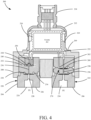
- FIG. 6 is a diagrammatic view of a portion of a coplanar differential pressure sensor module having an overpressure protection feature in accordance with an embodiment of the present invention. For clarity, the transmitter housing and electronics are not shown in FIG. 6 .
- FIG. 6 shows an overpressure (illustrated diagrammatically at arrow 500) being applied to process fluid pressure port 224.
- overpressure illustrated diagrammatically at arrow 500
- isolation diaphragm 230 is urged completely against and contacts isolation plug 232. Accordingly, isolation diaphragm 230 is considered to be bottomed out.
- process fluid within passageway 208 is also in fluidic communication with overpressure protection diaphragm 270 by virtue of overpressure protection fluid conduit 502. This allows overpressure protection diaphragm 270 to deform further to allow the isolation diaphragm 230 to bottom out and isolation diaphragm 256 to become fully extended. Once isolation diaphragm 230 is bottomed out, any additional pressure will not be conveyed to differential pressure sensor 218.
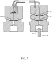
- FIG. 7 shows an overpressure 500 being applied to process fluid pressure port 254 thereby causing isolation diaphragm 256 to bottom out.
- overpressure protection diaphragm 270 is urged toward the high side, which causes isolation diaphragm 230 to be extended.
- pressure to differential pressure sensor 218 is maintained below a pressure rating of the differential pressure sensor by a suitably designed overpressure protection diaphragm, thereby preventing damage or other undesirable effects to the differential pressure sensor.
- a suitably designed overpressure protection diaphragm is stiff enough to prevent bottoming out of either isolator diaphragms before the maximum differential pressure of the sensor is reached.
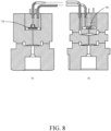
- FIG. 8 is a diagrammatic view of a portion of a coplanar differential pressure sensor module in accordance with another embodiment of the present invention. Some aspects of the embodiment shown in FIG. 8 are similar to those of FIGS. 6 and 7 , and like components are numbered similarly. With respect to FIG. 8 , the difference between the embodiment shown in that figure and the previous embodiments is the inclusion of a discrete line pressure sensor 700. Accordingly, while differential pressure sensor 718 provides a direct indication of a difference in pressure between pressure P1 and pressure P2, pressure sensor 700 provides a direct indication of the line pressure. This may be useful to provide a warning or compensation as the line pressure approaches and even exceeds selected pressure ratings. Further, while the embodiment shown in FIG.
Landscapes
- Physics & Mathematics (AREA)
- General Physics & Mathematics (AREA)
- Chemical & Material Sciences (AREA)
- Analytical Chemistry (AREA)
- Measuring Fluid Pressure (AREA)
Claims (13)
- Module capteur de pression différentielle (100, 200) comprenant :une base (108, 208) définissant une chambre de capteur (240) avec une entrée de chambre de capteur, la base (108, 208) présentant également une paire d'entrées de pression de fluide de processus (104, 106, 224, 254), chacune configurée pour recevoir une pression de fluide de processus respective (P1, P2) ;un capteur de pression différentielle (218, 300) disposé dans la chambre de capteur (240) et présentant une entrée (250), configuré pour recevoir une première pression de fluide de processus (P2) et fournir un signal indiquant une différence entre la première pression de fluide de processus (P2) et une pression de chambre de capteur (P1) externe au capteur de pression différentielle (218, 300) dans la chambre de capteur (240) ;une paire de membranes d'isolation (230, 256) disposées sensiblement dans le même plan, chacune scellant une entrée de pression de fluide de processus respective (104, 106, 224, 254) ;un premier passage de fluide (258) couplé fluidiquement à l'une des membranes d'isolation (256) et à l'entrée (250) du capteur de pression différentielle (218, 300) ;un second passage de fluide (236) couplé fluidiquement à l'autre membrane d'isolation (230) et à l'entrée de chambre de capteur ; etun dispositif de protection contre la surpression (270) couplé fluidiquement à la chambre de capteur (240), au premier passage de fluide (258) et au second passage de fluide (236), dans lequel le dispositif de protection contre la surpression (270) inclut une membrane de protection contre la surpression (260) couplée fluidiquement à chacun des premier et second passages de fluide (258, 236), dans lequel la membrane de protection contre la surpression (260) est configurée pour avoir un déplacement plus important que chacune des membranes d'isolation (230, 256),et dans lequel le dispositif de protection contre la surpression (270) protège le capteur de pression différentielle (218, 300) lorsqu'une surpression est appliquée à l'une des entrées de pression de fluide de processus (104, 106, 224, 254).
- Module capteur de pression différentielle (100, 200) selon la revendication 1, dans lequel le module capteur de pression différentielle (100, 200) a une pression de travail nominale supérieure à une pression nominale du capteur de pression différentielle (218, 300).
- Module capteur de pression différentielle (100, 200) selon la revendication 2, dans lequel le module capteur de pression différentielle (100, 200) a une pression de travail nominale d'environ 0,1379 GPa (20 000 psi).
- Module capteur de pression différentielle (100, 200) selon la revendication 1, comprenant en outre un boîtier (216) couplé à la base (108, 208), le boîtier (216) contenant une électronique (217).
- Module capteur de pression différentielle (100, 200) selon la revendication 4, dans lequel le module capteur de pression différentielle (100, 200) est entièrement soudé.
- Module capteur de pression différentielle (100, 200) selon la revendication 5, dans lequel la base (108, 208) inclut une surface annulaire (109) configurée pour recevoir un embout de palier haute pression (120).
- Module capteur de pression différentielle (100, 200) selon la revendication 6, dans lequel l'embout de palier haute pression (120) est soudé à la surface annulaire (109) de la base (108, 208).
- Module capteur de pression différentielle (100, 200) selon la revendication 1, comprenant en outre un capteur de pression de ligne (700) couplé fluidiquement à l'un des premier et second passages de fluide (258, 236).
- Module capteur de pression différentielle (100, 200) selon la revendication 8, dans lequel le capteur de pression de ligne (700) est espacé du capteur de pression différentielle (218, 300).
- Module capteur de pression différentielle (100, 200) selon la revendication 1, dans lequel chacune des membranes d'isolation (230, 256) a un diamètre ne dépassant pas environ 1,27 cm (0,5 pouces).
- Module capteur de pression différentielle (100, 200) selon la revendication 1, dans lequel l'électronique (217) est couplée fonctionnellement au capteur de pression différentielle (218, 300).
- Module capteur de pression différentielle (100, 200) selon la revendication 11, comprenant en outre un capteur de température (156) couplé à l'électronique (217), dans lequel l'électronique (217) inclut un dispositif de commande (152) configuré pour fournir une sortie de pression différentielle compensée en température.
- Module capteur de pression différentielle (100, 200) selon la revendication 12, et dans lequel l'électronique (217) inclut un module de communication (150) couplé au dispositif de commande (152) et configuré pour communiquer la sortie de pression différentielle compensée en température conformément à un protocole de communication de processus.
Applications Claiming Priority (2)
| Application Number | Priority Date | Filing Date | Title |
|---|---|---|---|
| US15/625,376 US10627302B2 (en) | 2017-06-16 | 2017-06-16 | Pressure sensor module for high working pressure applications |
| PCT/US2018/035062 WO2018231520A1 (fr) | 2017-06-16 | 2018-05-30 | Module capteur de pression pour des applications à haute pression de service |
Publications (3)
| Publication Number | Publication Date |
|---|---|
| EP3638998A1 EP3638998A1 (fr) | 2020-04-22 |
| EP3638998A4 EP3638998A4 (fr) | 2021-03-03 |
| EP3638998B1 true EP3638998B1 (fr) | 2024-05-29 |
Family
ID=62248253
Family Applications (1)
| Application Number | Title | Priority Date | Filing Date |
|---|---|---|---|
| EP18817163.1A Active EP3638998B1 (fr) | 2017-06-16 | 2018-05-30 | Module capteur de pression pour des applications à haute pression de service |
Country Status (5)
| Country | Link |
|---|---|
| US (1) | US10627302B2 (fr) |
| EP (1) | EP3638998B1 (fr) |
| JP (1) | JP2020524270A (fr) |
| CN (2) | CN207456671U (fr) |
| WO (1) | WO2018231520A1 (fr) |
Families Citing this family (15)
| Publication number | Priority date | Publication date | Assignee | Title |
|---|---|---|---|---|
| WO2019222598A1 (fr) | 2018-05-17 | 2019-11-21 | Rosemount Inc. | Élément de mesure et dispositif de mesure le comprenant |
| US11002582B2 (en) * | 2018-09-28 | 2021-05-11 | Rosemount Inc. | Process transmitter with thermal fluid detection for decreasing damage to the process transmitter components |
| US11137308B2 (en) * | 2019-01-02 | 2021-10-05 | Baker Hughes, A Ge Company, Llc | High sensitivity pressure sensor package |
| DE102019205154A1 (de) * | 2019-04-10 | 2020-10-15 | Robert Bosch Gmbh | Drucksensor zur Druckerfassung fluider Medien und Drucksensoreinrichtung mit einem solchen Drucksensor |
| DE102020121585A1 (de) | 2020-08-17 | 2022-02-17 | Endress+Hauser SE+Co. KG | Differenzdruckmessaufnehmer zur Bestimmung des Differenzdrucks von zwei Drücken |
| WO2021122775A1 (fr) | 2019-12-20 | 2021-06-24 | Endress+Hauser SE+Co. KG | Capteur de pression différentielle permettant de déterminer la pression différentielle entre deux pressions |
| US11573147B2 (en) * | 2020-06-30 | 2023-02-07 | Allen Bishop | Temperature compensated differential pressure system |
| DE102020121582A1 (de) | 2020-08-17 | 2022-02-17 | Endress+Hauser SE+Co. KG | Differenzdruckmessaufnehmer zur Bestimmung des Differenzdrucks von zwei Drücken |
| DE102020121583A1 (de) | 2020-08-17 | 2022-02-17 | Endress+Hauser SE+Co. KG | Differenzdruckmessaufnehmer |
| CN214471485U (zh) * | 2020-10-18 | 2021-10-22 | 武汉飞恩微电子有限公司 | 烧结座、芯体结构以及压力传感器 |
| CN112129453A (zh) * | 2020-10-18 | 2020-12-25 | 武汉飞恩微电子有限公司 | 烧结座、芯体结构、基座组件以及压差传感器 |
| DE102020132960A1 (de) | 2020-12-10 | 2022-06-15 | Endress+Hauser SE+Co. KG | Differenzdruckmessaufnehmer mit Überlastschutz |
| DE102021130134A1 (de) * | 2021-11-18 | 2023-05-25 | Gemü Gebr. Müller Apparatebau Gmbh & Co. Kommanditgesellschaft | Vorrichtung zur Fluidbegrenzung und Vorrichtung zum Messen einer Eigenschaft eines Prozessfluids |
| CN119492477B (zh) * | 2023-08-14 | 2025-10-28 | 精量电子(深圳)有限公司 | 压差传感器和压差检测装置 |
| CN119688767B (zh) * | 2024-12-16 | 2026-03-24 | 广州海洋地质调查局 | 一种监测仪 |
Family Cites Families (28)
| Publication number | Priority date | Publication date | Assignee | Title |
|---|---|---|---|---|
| CA1077294A (fr) | 1976-05-03 | 1980-05-13 | Honeywell Inc. | Transducteur de pression a sonde de pression simplifiee |
| US4218925A (en) * | 1979-06-27 | 1980-08-26 | Honeywell Inc. | Differential pressure transmitter with pressure sensor protection |
| JPS6120831A (ja) * | 1984-07-10 | 1986-01-29 | Toshiba Corp | 差圧伝送器 |
| JPS6120832A (ja) * | 1984-07-10 | 1986-01-29 | Toshiba Corp | 差圧伝送器 |
| US4612812A (en) | 1985-08-15 | 1986-09-23 | Rosemount Inc. | Stress reducing stop for unstretched pressure sensing diaphragm |
| JPS638524A (ja) * | 1986-06-30 | 1988-01-14 | Yamatake Honeywell Co Ltd | 差圧発信器 |
| JPH05346363A (ja) * | 1992-06-16 | 1993-12-27 | Hitachi Ltd | 差圧伝送器 |
| JPH07229807A (ja) * | 1994-02-21 | 1995-08-29 | Yokogawa Electric Corp | 差圧測定装置 |
| JPH09145518A (ja) * | 1995-11-17 | 1997-06-06 | Yamatake Honeywell Co Ltd | 差圧・圧力発信器 |
| JP3900351B2 (ja) * | 2003-07-30 | 2007-04-04 | 横河電機株式会社 | 差圧測定装置 |
| US6918303B2 (en) | 2003-08-12 | 2005-07-19 | Invensys | Bi-planar differential pressure transmitter with orthogonal process connections |
| US7188529B2 (en) * | 2005-01-25 | 2007-03-13 | Yokogawa Electric Corporation | Differential pressure measuring apparatus |
| US7334484B2 (en) * | 2005-05-27 | 2008-02-26 | Rosemount Inc. | Line pressure measurement using differential pressure sensor |
| US20110320142A1 (en) | 2010-06-28 | 2011-12-29 | General Electric Company | Temperature independent pressure sensor and associated methods thereof |
| US7624642B2 (en) * | 2007-09-20 | 2009-12-01 | Rosemount Inc. | Differential pressure sensor isolation in a process fluid pressure transmitter |
| JP2009180621A (ja) * | 2008-01-31 | 2009-08-13 | Yokogawa Electric Corp | 差圧測定装置 |
| JP2010074582A (ja) | 2008-09-19 | 2010-04-02 | Audio Technica Corp | フレキシブルパイプに対するマイクコードの挿通方法 |
| DE102009001133A1 (de) | 2009-02-25 | 2010-08-26 | Endress + Hauser Gmbh + Co. Kg | Drucksensor mit Halbleiterdruckmesswandler |
| US8448519B2 (en) | 2010-10-05 | 2013-05-28 | Rosemount Inc. | Industrial process transmitter with high static pressure isolation diaphragm coupling |
| US8776608B2 (en) * | 2011-10-31 | 2014-07-15 | Rosemount Inc. | Coplanar process fluid pressure sensor module |
| US9010191B2 (en) | 2011-12-22 | 2015-04-21 | Rosemount Inc. | Pressure sensor module for sub-sea applications |
| JP5912675B2 (ja) * | 2012-03-05 | 2016-04-27 | アズビル株式会社 | 差圧発信器 |
| US8752433B2 (en) * | 2012-06-19 | 2014-06-17 | Rosemount Inc. | Differential pressure transmitter with pressure sensor |
| US9250149B2 (en) | 2013-06-19 | 2016-02-02 | General Electric Company | Retrievable sensor and method |
| WO2015031785A1 (fr) | 2013-08-30 | 2015-03-05 | American Air & Water, Inc. | Système d'éclairage ultraviolet de désinfection |
| US9234776B2 (en) * | 2013-09-26 | 2016-01-12 | Rosemount Inc. | Multivariable process fluid transmitter for high pressure applications |
| US9310267B2 (en) * | 2014-02-28 | 2016-04-12 | Measurement Specialities, Inc. | Differential pressure sensor |
| JP2017050439A (ja) | 2015-09-03 | 2017-03-09 | 豊田合成株式会社 | 紫外発光素子およびその製造方法 |
-
2017
- 2017-06-16 US US15/625,376 patent/US10627302B2/en active Active
- 2017-07-14 CN CN201720860223.4U patent/CN207456671U/zh not_active Expired - Fee Related
- 2017-07-14 CN CN201710578669.2A patent/CN109141734B/zh active Active
-
2018
- 2018-05-30 WO PCT/US2018/035062 patent/WO2018231520A1/fr not_active Ceased
- 2018-05-30 JP JP2019569781A patent/JP2020524270A/ja active Pending
- 2018-05-30 EP EP18817163.1A patent/EP3638998B1/fr active Active
Also Published As
| Publication number | Publication date |
|---|---|
| US20180364124A1 (en) | 2018-12-20 |
| EP3638998A4 (fr) | 2021-03-03 |
| US10627302B2 (en) | 2020-04-21 |
| JP2020524270A (ja) | 2020-08-13 |
| EP3638998A1 (fr) | 2020-04-22 |
| CN207456671U (zh) | 2018-06-05 |
| CN109141734B (zh) | 2022-05-10 |
| WO2018231520A1 (fr) | 2018-12-20 |
| CN109141734A (zh) | 2019-01-04 |
Similar Documents
| Publication | Publication Date | Title |
|---|---|---|
| EP3638998B1 (fr) | Module capteur de pression pour des applications à haute pression de service | |
| EP2191249B1 (fr) | Isolation améliorée d'un capteur de pression différentielle dans un transmetteur de pression de fluide industriel | |
| EP2002233B1 (fr) | Ensemble transmetteur de mesure de pression haute température | |
| JP6182261B2 (ja) | 高圧用途向けの多変数プロセス流体伝送器 | |
| EP1759182B1 (fr) | Ensemble transmetteur de mesure de pression a haute temperature | |
| EP2761264B1 (fr) | Emetteur de pression de fluide de processus dont le capteur est séparé du circuit électronique de capteur | |
| EP2304404B1 (fr) | Système d'isolement amélioré pour la mesure d'une pression de procédé | |
| EP3356777B1 (fr) | Transmetteur de pression ayant une protection contre une surpression | |
| WO2013096410A1 (fr) | Module de capteur de pression pour applications sous-marines | |
| JP7602018B2 (ja) | 感圧機能付きサーモウェル | |
| CN113091992B (zh) | 高量程压差传感器 |
Legal Events
| Date | Code | Title | Description |
|---|---|---|---|
| STAA | Information on the status of an ep patent application or granted ep patent |
Free format text: STATUS: THE INTERNATIONAL PUBLICATION HAS BEEN MADE |
|
| PUAI | Public reference made under article 153(3) epc to a published international application that has entered the european phase |
Free format text: ORIGINAL CODE: 0009012 |
|
| STAA | Information on the status of an ep patent application or granted ep patent |
Free format text: STATUS: REQUEST FOR EXAMINATION WAS MADE |
|
| 17P | Request for examination filed |
Effective date: 20191219 |
|
| AK | Designated contracting states |
Kind code of ref document: A1 Designated state(s): AL AT BE BG CH CY CZ DE DK EE ES FI FR GB GR HR HU IE IS IT LI LT LU LV MC MK MT NL NO PL PT RO RS SE SI SK SM TR |
|
| AX | Request for extension of the european patent |
Extension state: BA ME |
|
| DAV | Request for validation of the european patent (deleted) | ||
| DAX | Request for extension of the european patent (deleted) | ||
| A4 | Supplementary search report drawn up and despatched |
Effective date: 20210202 |
|
| RIC1 | Information provided on ipc code assigned before grant |
Ipc: G01L 13/02 20060101AFI20210127BHEP Ipc: G01L 19/06 20060101ALI20210127BHEP |
|
| REG | Reference to a national code |
Ref country code: DE Ref legal event code: R079 Free format text: PREVIOUS MAIN CLASS: G01L0013020000 Ipc: G01L0009000000 Ref country code: DE Ref legal event code: R079 Ref document number: 602018070124 Country of ref document: DE Free format text: PREVIOUS MAIN CLASS: G01L0013020000 Ipc: G01L0009000000 |
|
| RIC1 | Information provided on ipc code assigned before grant |
Ipc: G01L 19/06 20060101ALI20231123BHEP Ipc: G01L 19/00 20060101ALI20231123BHEP Ipc: G01L 13/02 20060101ALI20231123BHEP Ipc: G01L 9/00 20060101AFI20231123BHEP |
|
| GRAP | Despatch of communication of intention to grant a patent |
Free format text: ORIGINAL CODE: EPIDOSNIGR1 |
|
| STAA | Information on the status of an ep patent application or granted ep patent |
Free format text: STATUS: GRANT OF PATENT IS INTENDED |
|
| INTG | Intention to grant announced |
Effective date: 20240110 |
|
| GRAS | Grant fee paid |
Free format text: ORIGINAL CODE: EPIDOSNIGR3 |
|
| GRAA | (expected) grant |
Free format text: ORIGINAL CODE: 0009210 |
|
| STAA | Information on the status of an ep patent application or granted ep patent |
Free format text: STATUS: THE PATENT HAS BEEN GRANTED |
|
| P01 | Opt-out of the competence of the unified patent court (upc) registered |
Effective date: 20240403 |
|
| AK | Designated contracting states |
Kind code of ref document: B1 Designated state(s): AL AT BE BG CH CY CZ DE DK EE ES FI FR GB GR HR HU IE IS IT LI LT LU LV MC MK MT NL NO PL PT RO RS SE SI SK SM TR |
|
| REG | Reference to a national code |
Ref country code: CH Ref legal event code: EP |
|
| REG | Reference to a national code |
Ref country code: IE Ref legal event code: FG4D |
|
| REG | Reference to a national code |
Ref country code: DE Ref legal event code: R096 Ref document number: 602018070124 Country of ref document: DE |
|
| PGFP | Annual fee paid to national office [announced via postgrant information from national office to epo] |
Ref country code: CH Payment date: 20240619 Year of fee payment: 7 |
|
| REG | Reference to a national code |
Ref country code: LT Ref legal event code: MG9D |
|
| REG | Reference to a national code |
Ref country code: NL Ref legal event code: MP Effective date: 20240529 |
|
| PG25 | Lapsed in a contracting state [announced via postgrant information from national office to epo] |
Ref country code: IS Free format text: LAPSE BECAUSE OF FAILURE TO SUBMIT A TRANSLATION OF THE DESCRIPTION OR TO PAY THE FEE WITHIN THE PRESCRIBED TIME-LIMIT Effective date: 20240929 |
|
| PG25 | Lapsed in a contracting state [announced via postgrant information from national office to epo] |
Ref country code: BG Free format text: LAPSE BECAUSE OF FAILURE TO SUBMIT A TRANSLATION OF THE DESCRIPTION OR TO PAY THE FEE WITHIN THE PRESCRIBED TIME-LIMIT Effective date: 20240529 |
|
| PG25 | Lapsed in a contracting state [announced via postgrant information from national office to epo] |
Ref country code: HR Free format text: LAPSE BECAUSE OF FAILURE TO SUBMIT A TRANSLATION OF THE DESCRIPTION OR TO PAY THE FEE WITHIN THE PRESCRIBED TIME-LIMIT Effective date: 20240529 Ref country code: FI Free format text: LAPSE BECAUSE OF FAILURE TO SUBMIT A TRANSLATION OF THE DESCRIPTION OR TO PAY THE FEE WITHIN THE PRESCRIBED TIME-LIMIT Effective date: 20240529 |
|
| PG25 | Lapsed in a contracting state [announced via postgrant information from national office to epo] |
Ref country code: GR Free format text: LAPSE BECAUSE OF FAILURE TO SUBMIT A TRANSLATION OF THE DESCRIPTION OR TO PAY THE FEE WITHIN THE PRESCRIBED TIME-LIMIT Effective date: 20240830 |
|
| REG | Reference to a national code |
Ref country code: AT Ref legal event code: MK05 Ref document number: 1691020 Country of ref document: AT Kind code of ref document: T Effective date: 20240529 |
|
| PG25 | Lapsed in a contracting state [announced via postgrant information from national office to epo] |
Ref country code: ES Free format text: LAPSE BECAUSE OF FAILURE TO SUBMIT A TRANSLATION OF THE DESCRIPTION OR TO PAY THE FEE WITHIN THE PRESCRIBED TIME-LIMIT Effective date: 20240529 |
|
| PG25 | Lapsed in a contracting state [announced via postgrant information from national office to epo] |
Ref country code: AT Free format text: LAPSE BECAUSE OF FAILURE TO SUBMIT A TRANSLATION OF THE DESCRIPTION OR TO PAY THE FEE WITHIN THE PRESCRIBED TIME-LIMIT Effective date: 20240529 |
|
| PG25 | Lapsed in a contracting state [announced via postgrant information from national office to epo] |
Ref country code: PL Free format text: LAPSE BECAUSE OF FAILURE TO SUBMIT A TRANSLATION OF THE DESCRIPTION OR TO PAY THE FEE WITHIN THE PRESCRIBED TIME-LIMIT Effective date: 20240529 |
|
| PG25 | Lapsed in a contracting state [announced via postgrant information from national office to epo] |
Ref country code: LV Free format text: LAPSE BECAUSE OF FAILURE TO SUBMIT A TRANSLATION OF THE DESCRIPTION OR TO PAY THE FEE WITHIN THE PRESCRIBED TIME-LIMIT Effective date: 20240529 |
|
| PG25 | Lapsed in a contracting state [announced via postgrant information from national office to epo] |
Ref country code: PL Free format text: LAPSE BECAUSE OF FAILURE TO SUBMIT A TRANSLATION OF THE DESCRIPTION OR TO PAY THE FEE WITHIN THE PRESCRIBED TIME-LIMIT Effective date: 20240529 Ref country code: NO Free format text: LAPSE BECAUSE OF FAILURE TO SUBMIT A TRANSLATION OF THE DESCRIPTION OR TO PAY THE FEE WITHIN THE PRESCRIBED TIME-LIMIT Effective date: 20240829 Ref country code: LV Free format text: LAPSE BECAUSE OF FAILURE TO SUBMIT A TRANSLATION OF THE DESCRIPTION OR TO PAY THE FEE WITHIN THE PRESCRIBED TIME-LIMIT Effective date: 20240529 Ref country code: IS Free format text: LAPSE BECAUSE OF FAILURE TO SUBMIT A TRANSLATION OF THE DESCRIPTION OR TO PAY THE FEE WITHIN THE PRESCRIBED TIME-LIMIT Effective date: 20240929 Ref country code: HR Free format text: LAPSE BECAUSE OF FAILURE TO SUBMIT A TRANSLATION OF THE DESCRIPTION OR TO PAY THE FEE WITHIN THE PRESCRIBED TIME-LIMIT Effective date: 20240529 Ref country code: GR Free format text: LAPSE BECAUSE OF FAILURE TO SUBMIT A TRANSLATION OF THE DESCRIPTION OR TO PAY THE FEE WITHIN THE PRESCRIBED TIME-LIMIT Effective date: 20240830 Ref country code: FI Free format text: LAPSE BECAUSE OF FAILURE TO SUBMIT A TRANSLATION OF THE DESCRIPTION OR TO PAY THE FEE WITHIN THE PRESCRIBED TIME-LIMIT Effective date: 20240529 Ref country code: ES Free format text: LAPSE BECAUSE OF FAILURE TO SUBMIT A TRANSLATION OF THE DESCRIPTION OR TO PAY THE FEE WITHIN THE PRESCRIBED TIME-LIMIT Effective date: 20240529 Ref country code: BG Free format text: LAPSE BECAUSE OF FAILURE TO SUBMIT A TRANSLATION OF THE DESCRIPTION OR TO PAY THE FEE WITHIN THE PRESCRIBED TIME-LIMIT Effective date: 20240529 Ref country code: AT Free format text: LAPSE BECAUSE OF FAILURE TO SUBMIT A TRANSLATION OF THE DESCRIPTION OR TO PAY THE FEE WITHIN THE PRESCRIBED TIME-LIMIT Effective date: 20240529 Ref country code: RS Free format text: LAPSE BECAUSE OF FAILURE TO SUBMIT A TRANSLATION OF THE DESCRIPTION OR TO PAY THE FEE WITHIN THE PRESCRIBED TIME-LIMIT Effective date: 20240829 |
|
| PG25 | Lapsed in a contracting state [announced via postgrant information from national office to epo] |
Ref country code: NL Free format text: LAPSE BECAUSE OF FAILURE TO SUBMIT A TRANSLATION OF THE DESCRIPTION OR TO PAY THE FEE WITHIN THE PRESCRIBED TIME-LIMIT Effective date: 20240529 |
|
| PG25 | Lapsed in a contracting state [announced via postgrant information from national office to epo] |
Ref country code: NL Free format text: LAPSE BECAUSE OF FAILURE TO SUBMIT A TRANSLATION OF THE DESCRIPTION OR TO PAY THE FEE WITHIN THE PRESCRIBED TIME-LIMIT Effective date: 20240529 |
|
| PG25 | Lapsed in a contracting state [announced via postgrant information from national office to epo] |
Ref country code: DK Free format text: LAPSE BECAUSE OF FAILURE TO SUBMIT A TRANSLATION OF THE DESCRIPTION OR TO PAY THE FEE WITHIN THE PRESCRIBED TIME-LIMIT Effective date: 20240529 |
|
| PG25 | Lapsed in a contracting state [announced via postgrant information from national office to epo] |
Ref country code: LU Free format text: LAPSE BECAUSE OF NON-PAYMENT OF DUE FEES Effective date: 20240530 |
|
| PG25 | Lapsed in a contracting state [announced via postgrant information from national office to epo] |
Ref country code: EE Free format text: LAPSE BECAUSE OF FAILURE TO SUBMIT A TRANSLATION OF THE DESCRIPTION OR TO PAY THE FEE WITHIN THE PRESCRIBED TIME-LIMIT Effective date: 20240529 |
|
| PG25 | Lapsed in a contracting state [announced via postgrant information from national office to epo] |
Ref country code: CZ Free format text: LAPSE BECAUSE OF FAILURE TO SUBMIT A TRANSLATION OF THE DESCRIPTION OR TO PAY THE FEE WITHIN THE PRESCRIBED TIME-LIMIT Effective date: 20240529 |
|
| PG25 | Lapsed in a contracting state [announced via postgrant information from national office to epo] |
Ref country code: SK Free format text: LAPSE BECAUSE OF FAILURE TO SUBMIT A TRANSLATION OF THE DESCRIPTION OR TO PAY THE FEE WITHIN THE PRESCRIBED TIME-LIMIT Effective date: 20240529 Ref country code: RO Free format text: LAPSE BECAUSE OF FAILURE TO SUBMIT A TRANSLATION OF THE DESCRIPTION OR TO PAY THE FEE WITHIN THE PRESCRIBED TIME-LIMIT Effective date: 20240529 |
|
| PG25 | Lapsed in a contracting state [announced via postgrant information from national office to epo] |
Ref country code: SM Free format text: LAPSE BECAUSE OF FAILURE TO SUBMIT A TRANSLATION OF THE DESCRIPTION OR TO PAY THE FEE WITHIN THE PRESCRIBED TIME-LIMIT Effective date: 20240529 |
|
| PG25 | Lapsed in a contracting state [announced via postgrant information from national office to epo] |
Ref country code: SM Free format text: LAPSE BECAUSE OF FAILURE TO SUBMIT A TRANSLATION OF THE DESCRIPTION OR TO PAY THE FEE WITHIN THE PRESCRIBED TIME-LIMIT Effective date: 20240529 Ref country code: SK Free format text: LAPSE BECAUSE OF FAILURE TO SUBMIT A TRANSLATION OF THE DESCRIPTION OR TO PAY THE FEE WITHIN THE PRESCRIBED TIME-LIMIT Effective date: 20240529 Ref country code: RO Free format text: LAPSE BECAUSE OF FAILURE TO SUBMIT A TRANSLATION OF THE DESCRIPTION OR TO PAY THE FEE WITHIN THE PRESCRIBED TIME-LIMIT Effective date: 20240529 Ref country code: LU Free format text: LAPSE BECAUSE OF NON-PAYMENT OF DUE FEES Effective date: 20240530 Ref country code: EE Free format text: LAPSE BECAUSE OF FAILURE TO SUBMIT A TRANSLATION OF THE DESCRIPTION OR TO PAY THE FEE WITHIN THE PRESCRIBED TIME-LIMIT Effective date: 20240529 Ref country code: DK Free format text: LAPSE BECAUSE OF FAILURE TO SUBMIT A TRANSLATION OF THE DESCRIPTION OR TO PAY THE FEE WITHIN THE PRESCRIBED TIME-LIMIT Effective date: 20240529 Ref country code: CZ Free format text: LAPSE BECAUSE OF FAILURE TO SUBMIT A TRANSLATION OF THE DESCRIPTION OR TO PAY THE FEE WITHIN THE PRESCRIBED TIME-LIMIT Effective date: 20240529 |
|
| PG25 | Lapsed in a contracting state [announced via postgrant information from national office to epo] |
Ref country code: IT Free format text: LAPSE BECAUSE OF FAILURE TO SUBMIT A TRANSLATION OF THE DESCRIPTION OR TO PAY THE FEE WITHIN THE PRESCRIBED TIME-LIMIT Effective date: 20240529 Ref country code: MC Free format text: LAPSE BECAUSE OF FAILURE TO SUBMIT A TRANSLATION OF THE DESCRIPTION OR TO PAY THE FEE WITHIN THE PRESCRIBED TIME-LIMIT Effective date: 20240529 |
|
| REG | Reference to a national code |
Ref country code: BE Ref legal event code: MM Effective date: 20240531 |
|
| REG | Reference to a national code |
Ref country code: DE Ref legal event code: R097 Ref document number: 602018070124 Country of ref document: DE |
|
| PLBE | No opposition filed within time limit |
Free format text: ORIGINAL CODE: 0009261 |
|
| STAA | Information on the status of an ep patent application or granted ep patent |
Free format text: STATUS: NO OPPOSITION FILED WITHIN TIME LIMIT |
|
| PG25 | Lapsed in a contracting state [announced via postgrant information from national office to epo] |
Ref country code: IE Free format text: LAPSE BECAUSE OF NON-PAYMENT OF DUE FEES Effective date: 20240530 |
|
| GBPC | Gb: european patent ceased through non-payment of renewal fee |
Effective date: 20240829 |
|
| PG25 | Lapsed in a contracting state [announced via postgrant information from national office to epo] |
Ref country code: SI Free format text: LAPSE BECAUSE OF FAILURE TO SUBMIT A TRANSLATION OF THE DESCRIPTION OR TO PAY THE FEE WITHIN THE PRESCRIBED TIME-LIMIT Effective date: 20240529 Ref country code: BE Free format text: LAPSE BECAUSE OF NON-PAYMENT OF DUE FEES Effective date: 20240531 |
|
| PG25 | Lapsed in a contracting state [announced via postgrant information from national office to epo] |
Ref country code: FR Free format text: LAPSE BECAUSE OF NON-PAYMENT OF DUE FEES Effective date: 20240729 |
|
| 26N | No opposition filed |
Effective date: 20250303 |
|
| PGFP | Annual fee paid to national office [announced via postgrant information from national office to epo] |
Ref country code: DE Payment date: 20250423 Year of fee payment: 8 |
|
| PG25 | Lapsed in a contracting state [announced via postgrant information from national office to epo] |
Ref country code: GB Free format text: LAPSE BECAUSE OF NON-PAYMENT OF DUE FEES Effective date: 20240829 |
|
| PG25 | Lapsed in a contracting state [announced via postgrant information from national office to epo] |
Ref country code: SE Free format text: LAPSE BECAUSE OF FAILURE TO SUBMIT A TRANSLATION OF THE DESCRIPTION OR TO PAY THE FEE WITHIN THE PRESCRIBED TIME-LIMIT Effective date: 20240529 |
|
| PG25 | Lapsed in a contracting state [announced via postgrant information from national office to epo] |
Ref country code: CY Free format text: LAPSE BECAUSE OF FAILURE TO SUBMIT A TRANSLATION OF THE DESCRIPTION OR TO PAY THE FEE WITHIN THE PRESCRIBED TIME-LIMIT; INVALID AB INITIO Effective date: 20180530 |
|
| PG25 | Lapsed in a contracting state [announced via postgrant information from national office to epo] |
Ref country code: PT Free format text: LAPSE BECAUSE OF NON-PAYMENT OF DUE FEES Effective date: 20240529 |
|
| REG | Reference to a national code |
Ref country code: CH Ref legal event code: H13 Free format text: ST27 STATUS EVENT CODE: U-0-0-H10-H13 (AS PROVIDED BY THE NATIONAL OFFICE) Effective date: 20251223 |
|
| PG25 | Lapsed in a contracting state [announced via postgrant information from national office to epo] |
Ref country code: CH Free format text: LAPSE BECAUSE OF NON-PAYMENT OF DUE FEES Effective date: 20250531 |
|
| PG25 | Lapsed in a contracting state [announced via postgrant information from national office to epo] |
Ref country code: HU Free format text: LAPSE BECAUSE OF FAILURE TO SUBMIT A TRANSLATION OF THE DESCRIPTION OR TO PAY THE FEE WITHIN THE PRESCRIBED TIME-LIMIT; INVALID AB INITIO Effective date: 20180530 |