EP3639962A1 - Procédé de vérification de la qualité pendant le soudage par résistance de deux pièces - Google Patents
Procédé de vérification de la qualité pendant le soudage par résistance de deux pièces Download PDFInfo
- Publication number
- EP3639962A1 EP3639962A1 EP19193516.2A EP19193516A EP3639962A1 EP 3639962 A1 EP3639962 A1 EP 3639962A1 EP 19193516 A EP19193516 A EP 19193516A EP 3639962 A1 EP3639962 A1 EP 3639962A1
- Authority
- EP
- European Patent Office
- Prior art keywords
- welding
- point
- time
- value
- workpieces
- Prior art date
- Legal status (The legal status is an assumption and is not a legal conclusion. Google has not performed a legal analysis and makes no representation as to the accuracy of the status listed.)
- Withdrawn
Links
Images


Classifications
-
- B—PERFORMING OPERATIONS; TRANSPORTING
- B23—MACHINE TOOLS; METAL-WORKING NOT OTHERWISE PROVIDED FOR
- B23K—SOLDERING OR UNSOLDERING; WELDING; CLADDING OR PLATING BY SOLDERING OR WELDING; CUTTING BY APPLYING HEAT LOCALLY, e.g. FLAME CUTTING; WORKING BY LASER BEAM
- B23K11/00—Resistance welding; Severing by resistance heating
- B23K11/24—Electric supply or control circuits therefor
- B23K11/25—Monitoring devices
-
- G—PHYSICS
- G01—MEASURING; TESTING
- G01R—MEASURING ELECTRIC VARIABLES; MEASURING MAGNETIC VARIABLES
- G01R19/00—Arrangements for measuring currents or voltages or for indicating presence or sign thereof
- G01R19/25—Arrangements for measuring currents or voltages or for indicating presence or sign thereof using digital measurement techniques
- G01R19/257—Arrangements for measuring currents or voltages or for indicating presence or sign thereof using digital measurement techniques using analogue/digital converters of the type with comparison of different reference values with the value of voltage or current, e.g. using step-by-step method
-
- B—PERFORMING OPERATIONS; TRANSPORTING
- B23—MACHINE TOOLS; METAL-WORKING NOT OTHERWISE PROVIDED FOR
- B23K—SOLDERING OR UNSOLDERING; WELDING; CLADDING OR PLATING BY SOLDERING OR WELDING; CUTTING BY APPLYING HEAT LOCALLY, e.g. FLAME CUTTING; WORKING BY LASER BEAM
- B23K11/00—Resistance welding; Severing by resistance heating
- B23K11/10—Spot welding; Stitch welding
- B23K11/11—Spot welding
- B23K11/115—Spot welding by means of two electrodes placed opposite one another on both sides of the welded parts
-
- B—PERFORMING OPERATIONS; TRANSPORTING
- B23—MACHINE TOOLS; METAL-WORKING NOT OTHERWISE PROVIDED FOR
- B23K—SOLDERING OR UNSOLDERING; WELDING; CLADDING OR PLATING BY SOLDERING OR WELDING; CUTTING BY APPLYING HEAT LOCALLY, e.g. FLAME CUTTING; WORKING BY LASER BEAM
- B23K11/00—Resistance welding; Severing by resistance heating
- B23K11/24—Electric supply or control circuits therefor
- B23K11/25—Monitoring devices
- B23K11/252—Monitoring devices using digital means
- B23K11/253—Monitoring devices using digital means the measured parameter being a displacement or a position
-
- B—PERFORMING OPERATIONS; TRANSPORTING
- B23—MACHINE TOOLS; METAL-WORKING NOT OTHERWISE PROVIDED FOR
- B23K—SOLDERING OR UNSOLDERING; WELDING; CLADDING OR PLATING BY SOLDERING OR WELDING; CUTTING BY APPLYING HEAT LOCALLY, e.g. FLAME CUTTING; WORKING BY LASER BEAM
- B23K31/00—Processes relevant to this subclass, specially adapted for particular articles or purposes, but not covered by any single one of main groups B23K1/00 - B23K28/00
- B23K31/12—Processes relevant to this subclass, specially adapted for particular articles or purposes, but not covered by any single one of main groups B23K1/00 - B23K28/00 relating to investigating the properties, e.g. the weldability, of materials
- B23K31/125—Weld quality monitoring
-
- G—PHYSICS
- G01—MEASURING; TESTING
- G01R—MEASURING ELECTRIC VARIABLES; MEASURING MAGNETIC VARIABLES
- G01R23/00—Arrangements for measuring frequencies; Arrangements for analysing frequency spectra
- G01R23/02—Arrangements for measuring frequency, e.g. pulse repetition rate; Arrangements for measuring period of current or voltage
- G01R23/15—Indicating that frequency of pulses is either above or below a predetermined value or within or outside a predetermined range of values, by making use of non-linear or digital elements (indicating that pulse width is above or below a certain limit)
-
- B—PERFORMING OPERATIONS; TRANSPORTING
- B23—MACHINE TOOLS; METAL-WORKING NOT OTHERWISE PROVIDED FOR
- B23K—SOLDERING OR UNSOLDERING; WELDING; CLADDING OR PLATING BY SOLDERING OR WELDING; CUTTING BY APPLYING HEAT LOCALLY, e.g. FLAME CUTTING; WORKING BY LASER BEAM
- B23K11/00—Resistance welding; Severing by resistance heating
- B23K11/36—Auxiliary equipment
-
- B—PERFORMING OPERATIONS; TRANSPORTING
- B23—MACHINE TOOLS; METAL-WORKING NOT OTHERWISE PROVIDED FOR
- B23K—SOLDERING OR UNSOLDERING; WELDING; CLADDING OR PLATING BY SOLDERING OR WELDING; CUTTING BY APPLYING HEAT LOCALLY, e.g. FLAME CUTTING; WORKING BY LASER BEAM
- B23K2101/00—Articles made by soldering, welding or cutting
- B23K2101/006—Vehicles
-
- B—PERFORMING OPERATIONS; TRANSPORTING
- B23—MACHINE TOOLS; METAL-WORKING NOT OTHERWISE PROVIDED FOR
- B23K—SOLDERING OR UNSOLDERING; WELDING; CLADDING OR PLATING BY SOLDERING OR WELDING; CUTTING BY APPLYING HEAT LOCALLY, e.g. FLAME CUTTING; WORKING BY LASER BEAM
- B23K2101/00—Articles made by soldering, welding or cutting
- B23K2101/18—Sheet panels
-
- B—PERFORMING OPERATIONS; TRANSPORTING
- B23—MACHINE TOOLS; METAL-WORKING NOT OTHERWISE PROVIDED FOR
- B23K—SOLDERING OR UNSOLDERING; WELDING; CLADDING OR PLATING BY SOLDERING OR WELDING; CUTTING BY APPLYING HEAT LOCALLY, e.g. FLAME CUTTING; WORKING BY LASER BEAM
- B23K2103/00—Materials to be soldered, welded or cut
- B23K2103/02—Iron or ferrous alloys
- B23K2103/04—Steel or steel alloys
-
- B—PERFORMING OPERATIONS; TRANSPORTING
- B23—MACHINE TOOLS; METAL-WORKING NOT OTHERWISE PROVIDED FOR
- B23K—SOLDERING OR UNSOLDERING; WELDING; CLADDING OR PLATING BY SOLDERING OR WELDING; CUTTING BY APPLYING HEAT LOCALLY, e.g. FLAME CUTTING; WORKING BY LASER BEAM
- B23K2103/00—Materials to be soldered, welded or cut
- B23K2103/08—Non-ferrous metals or alloys
- B23K2103/10—Aluminium or alloys thereof
Definitions
- the present invention relates to a method for checking the quality in resistance welding of workpieces, as well as a control unit, a welding device and a computer program for carrying it out.
- workpieces can be connected to one another in a materially bonded manner.
- different workpieces e.g. Sheets welded together using resistance welding.
- Welding electrodes are pressed with the aid of an electrode drive with an electrode force against a welding point of the workpieces and in the course of a welding process the welding electrodes are energized with a welding current in order to liquefy or melt a surface of the workpieces.
- the welding current strength is increased up to a predetermined value at the beginning of the welding process in the course of a so-called current build-up phase.
- the welding current strength is expediently reduced to the value zero in the course of a so-called current reduction phase.
- a first value of a welding electrode parameter characterizing a position of one or both electrodes is determined at a first point in time. At this first point in time, the welding electrodes are pressed against the welding point of the workpieces with the electrode force before the liquefaction begins. At a second point in time after the start of liquefaction, a second value of the welding electrode parameter is determined, at which second point the welding electrodes are pressed against the welding point of the workpieces with the electrode force.
- the first point in time is in particular a point in time before a start or during the first phases of the welding process, at which the material surfaces have not yet liquefied or melted. Either no welding current is flowing at the first point in time or a welding current is already flowing, but it is still so low that the workpiece surfaces are not yet liquefied.
- the second point in time is in particular a point in time during the last phases or after the end of the welding process.
- the workpiece surfaces can already be solidified again at the second point in time. Either there is no longer any welding current flowing at the second point in time or a welding current is still flowing, but this is too low to allow further liquefaction.
- the second point in time is after the end of the liquefaction, ie no further one is found Phase transition from solid to liquid takes place, especially after the start of solidification, ie there is already a phase transition from liquid to solid, especially after the end of solidification, ie the workpiece surfaces are already solid again.
- the first value and the second value are compared with one another and, depending on a comparison result, a quality of the welding process is assessed.
- the welding electrode parameter and in particular its first and second values before or after the start of liquefaction represent a particularly effective way of assessing and further quantifying the quality of the welding process.
- the welding electrode parameters characterizing a position of one or both electrodes characterize a position or position of the welding electrodes.
- the actual position value can be determined relative to the welding point or the workpieces or expediently also in relation to a reference point of the welding device, in particular to a rest position of the welding electrodes.
- the position or the actual position value characterizes the position of the electrode caps in the room.
- only one axis is considered, expediently an axis in the direction of movement of the electrodes, which can be given by an actual position value of a drive that opens and closes the electrodes.
- the first value thus describes the position or location before the start of the liquefaction of the workpiece surfaces and thus in particular before or at the start of the welding process, expediently relative to the welding point.
- the second value describes the position after the start of the liquefaction of the workpiece surfaces and thus in particular after or at the end of the welding process, also in particular relative to the welding point.
- a comparison of the first and second values in particular allows conclusions to be drawn as to how the position of the welding electrodes relative to the welding point and thus also how the workpieces at the welding point have changed during the welding process. This comparison thus enables meaningful conclusions to be drawn about the quality of the welded connection of the workpieces produced at the welding point and thus about the quality of the welding process.
- the actual position value represents a particularly advantageous welding electrode parameter in order to draw conclusions about the properties and conditions of the welding process and in particular to be able to assess the quality of the welding process. Since liquid metal is removed from the workpieces in welding spatter, this means that the welding electrodes are moved further towards the workpieces and the actual position value in particular increases.
- values of the welding electrode parameter can also be determined between the first and the second point in time, that is to say in particular during the welding process, and used for the evaluation of the quality.
- the welding process can thus be monitored continuously, in particular with the aid of the welding electrode parameter.
- the first point in time is a point in time at which the welding electrodes are pressed against the welding point of the workpieces with the electrode force but are not yet supplied with current by the welding current.
- the first point in time in this case takes place before the start of the welding process.
- the first point in time in this case can be the so-called lead phase, which in resistance welding lies between the force build-up phase and the start of the welding process.
- the second point in time is advantageously a point in time at which the welding electrodes are no longer supplied with current, but are still pressed against the welding point of the workpieces with the electrode force.
- the second point in time therefore takes place in particular after the end of the welding process.
- the second point in time can be, for example, in the so-called follow-up phase, in particular after the end of the welding process before the welding electrodes are moved away from the welding point.
- a welding current to flow at the first and / or second point in time, in particular not causing the surfaces to liquefy.
- the first point in time is preferably a point in time during a current build-up phase, that is to say while the welding current strength increases after the start of energizing the welding electrodes.
- the first point in time is preferably a point in time during a so-called preconditioning phase, during which, in particular, a welding current is already flowing through the welding electrodes, but whose welding current strength is still too low, so that the workpiece surfaces are not yet liquefied.
- the first point in time is preferably a point in time within the first 10% of the duration of the welding time.
- the second point in time is preferably a point in time during a current reduction phase, that is to say while the welding current is reduced to the value zero.
- the second point in time is preferably a point in time during a so-called reheating phase, during which a welding current still flows through the welding electrodes, but the welding current strength is already too low to liquefy the workpiece surfaces even further.
- the second point in time is a point in time within the last 10% of the duration of the welding time.
- the effects of welding spatter on the quality of the welding process are quantified from the first value and the second value.
- Drops of molten metal are to be understood as welding spatters, which break out due to the extreme intensity of heat and force that is applied to or around the welding point. Such welding spatter can negatively influence the welding quality, since the material lost at the welding point is no longer available.
- the welding electrodes are moved further towards the workpieces or towards one another when a welding spatter occurs, and the current position or position of the welding electrodes changes.
- the welding electrode parameter which in particular characterizes the position or position of the welding electrodes relative to the welding point, the effects of welding spatter can be assessed and in particular quantified.
- a difference between the first value and the second value is advantageously formed and this difference is compared with at least one threshold value.
- This difference expediently quantifies the change in the position of the welding electrodes relative to the welding point during the welding process and furthermore in particular the change in the workpieces at the welding point.
- This difference therefore represents a particularly advantageous quantitative quantity in order to be able to assess the quality of the welding process.
- An impression depth and / or a residual wall thickness of the welding point are preferably assessed as the quality of the welding process.
- the depth of indentation should in particular be understood as how deep the welding electrodes penetrate into the workpieces at the welding point in the course of the welding process.
- the residual wall thickness is to be understood in particular as the thickness of the workpieces connected at the welding point.
- both the depth of impression and the remaining wall thickness characterize the change in the workpieces at the welding point and allow a statement about the quality of the welding process.
- the depth of indentation can be deduced from the welding electrode parameter, which characterizes the position of the welding electrodes.
- the depth of indentation can expediently be used to draw conclusions about the remaining wall thickness and from this in particular the quality of the welding process.
- the indentation depth and / or a residual wall thickness of the welding point are preferably quantified from the first value and the second value.
- the welding electrode parameters characterizing the position of the welding electrodes and in particular its first value immediately before and its second value immediately after the welding process thus represent a particularly advantageous possibility for determining such quantitative quantities for assessing the welding process quality.
- the welding electrode parameter is advantageously a drive parameter of the electrode drive.
- drive parameters are to be understood in particular as variables or parameters which are determined in the course of regulation or control of the electrode drive in order to move the welding electrodes in a predetermined manner and to press them against the workpieces.
- the drive parameter characterizes the current position or position or movement of the welding electrodes. It is therefore expedient to draw conclusions from the values of the drive parameter about the current position of the welding electrodes and, based on this, again about the welding process or the properties of the workpieces.
- the drive parameter is therefore particularly advantageous for assessing the quality of the welding process.
- the drive parameter can be a control and / or regulation variable of the electrode drive, in particular an actual value and / or target value of the electrode drive, which are determined in the course of the regulation of the electrode drive in order to regulate the electrode force to a predetermined value.
- the electrode drive can in particular be an electrical and / or mechanical and / or pneumatic electrode drive.
- the drive parameter can therefore be, for example, a corresponding electrical and / or mechanical and / or pneumatic variable.
- a possibility is thus provided for using drive parameters, which are determined for the regulation or control of the electrode drive, for the assessment of the quality of the welding process.
- the electrode drive is usually controlled in resistance welding, usually by means of a corresponding drive control device, and the welding process is controlled independently thereof, mostly by means of a separate, independent welding control.
- parameters of the drive control cannot usually be accessed.
- drive parameters of the regulation of the electrode drive are included for the assessment of the quality of the welding process.
- the present method thus advantageously provides a possibility of linking the controls of the welding process and the electrode drive with one another and integrating the drive parameters, which are usually determined anyway for the control of the electrode drive, into the control of the welding process for assessing the welding process quality.
- BDK sheet thicknesses
- the welding area required for a special sheet thickness combination is very narrow, i.e. the area where a good quality of the welding process can be achieved. This results in the risk of resistance welding of a special combination of sheet thickness to migrate out of the corresponding welding area, which increases the number of weld spatter and the quality of the welded connection. Therefore, the combination of sheet thicknesses of the workpieces to be welded is advantageously also taken into account in the process for assessing the quality of the welding process. In the course of the quality assessment, for example, the remaining wall thickness of the welding spot remaining after the welding process can be compared with the thickness of the workpieces and thus it can be assessed whether the welding spot is formed but does not achieve the necessary strength.
- the present method is therefore particularly advantageous for processes in which a multiplicity of welding points with complex, different combinations of sheet thickness are to be welded to one another.
- the method is particularly advantageous for the body shop, in particular for automated welding processes in the body shop, preferably in the course of a motor vehicle production.
- sheets are welded to one another in order to produce the body of a motor vehicle.
- up to several thousand weld spots with several hundred different sheet thickness combinations can be processed automatically, e.g. approx. 5,000 weld spots with approx. 700 different sheet thickness combinations for a medium-sized vehicle.
- the method allows the quality of the individual welding spots to be precisely assessed.
- At least one welding parameter is also taken into account in the course of the comparison.
- welding parameters are expediently understood to mean quantities or parameters which relate to the welding process itself and thus in particular an electrical operation of the welding electrodes.
- the welding current and / or a welding voltage and / or the current time or welding time can be taken into account as welding parameters. It is also conceivable to consider a reaction of the welding process control to the least one welding parameter.
- the workpieces made of aluminum and / or steel are preferred.
- the workpieces can, for example, be thin sheets with a thickness of in particular up to 1 mm. Resistance welding of such workpieces represents particularly difficult applications for precise welding process control. With the present method, the quality of the welding process in such difficult applications can be precisely assessed.
- a control unit (computing unit) according to the invention e.g. a welding controller of a welding device is, in particular in terms of program technology, set up to carry out a method according to the invention.
- the control unit or welding control can be designed, for example, as a PLC (programmable logic controller), as an NC (Numerical Control) or CNC (Computerized Numerical Control).
- a welding device for resistance welding has, in particular, a welding gun with welding electrodes and an electrode drive for moving the Welding electrodes. Furthermore, the welding device comprises a preferred embodiment of a control unit according to the invention.
- Suitable data carriers for providing the computer program are in particular magnetic, optical and electrical memories, such as Hard drives, flash memory, EEPROMs, DVDs, etc. It is also possible to download a program via computer networks (internet, intranet, etc.).
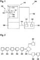
- FIG. 1 a welding device for resistance welding is shown schematically and designated 100.
- workpieces 120 can be connected to one another in a materially closed manner by resistance welding.
- the workpieces 120 are welded to one another in the course of a body shell construction, a body of a motor vehicle in particular being produced.
- Two aluminum sheets 121 and 122, for example, are welded together as workpieces.
- the welding device 100 has a welding gun 110 with two welding electrodes 111 and 112.
- An electrode drive 130 is provided to move the welding electrodes 111, 112.
- the welding gun 110 is shown, for example, as a servo-electric welding gun with an electrode drive 130 designed as a servo motor. It is also conceivable that the electrode drive 130 can be designed, for example, as an electric motor, hydraulic motor or pneumatic motor.
- the welding electrodes 111 and 112 are pressed against the sheets 121 and 122 at a welding point 125 with the aid of the electrode drive 130 with an electrode force.
- the welding electrodes 111 and 112 are then supplied with a welding current during the actual welding process for the duration of a welding time, as a result of which the sheets 121 and 122 are heated at the welding point 125 and the surface of the workpieces 121, 122 is liquefied.
- the welding device 100 has a control unit (welding control) 140, which can be designed, for example, as a PLC (programmable logic controller).
- the control unit 140 is set up to regulate the electrode drive 130, indicated by reference number 151, and furthermore the welding process, indicated by reference number 152.
- a corresponding drive control 141 and a corresponding welding process control 142 are carried out in the control unit 130, each of which is called corresponding control programs or can also be implemented as a common control program.
- the control unit 140 is also set up to assess a quality of the welding process or the weld spot 125 generated.
- the control unit 140 is set up, in particular in terms of programming, to carry out a preferred embodiment of a method according to the invention, which is shown in Figure 2 is shown schematically as a block diagram and below with reference to FIG Figures 1 and 2 is explained.
- Step 201 denotes the force build-up phase in which the welding electrodes 111 and 112 are pressed against the sheets 121 and 122 at the welding point 125 with the aid of the electrode drive 130 until the predetermined electrode force is reached.
- Step 202 denotes a so-called lead phase, during which the welding electrodes 111, 112 are pressed with the electrode force before the welding process begins against the welding point 125 of the workpieces 121, 122, but are not yet energized with the welding current.
- a first value of an actual position value of the electrode drive 130 which characterizes the current position of the welding electrodes 111, 112, is determined as a welding electrode parameter at a first point in time before the surfaces of the workpieces 121, 122 begin to liquefy.
- step 203 The welding process now takes place in step 203, in the course of which the welding electrodes 111, 112 are energized with the welding current for the duration of the welding time.
- the first value of the actual position value after the start of the welding process during the first phases can then be determined at a first point in time, which can be within up to 10% of the welding time, for example during a so-called preconditioning phase.
- a second value of the welding electrode parameter ie the actual position value of the electrode drive 130, is determined at a second point in time after the liquefaction of the surfaces of the workpieces 121, 122.
- the second point in time is already here after the end of the hardening.
- the second value of the actual position value can also be determined during the last phases before the end of the welding process if a low welding current is still flowing.
- the second value can be determined at a second point in time, which can be from 90% of the complete welding duration, for example during a so-called reheating phase.
- the first value and the second value of the actual position value are now compared with one another and, depending on a comparison result, a quality of the welding process or of the welding point 125 generated is assessed.
- a difference between the first value and the second value is formed in step 205.
- This difference characterizes in particular how the actual position value changed during the welding process. If welding spatter occurs during the welding process, liquid metal is removed from the workpieces 121, 122 at the welding point 125, the welding electrodes 111, 112 move further towards one another and the actual position value increases. This difference thus represents a particularly advantageous quantity in order to be able to assess and quantify the effects of welding spatter on the quality of the welding process.
- step 206 the difference is now compared with a threshold value.
- the threshold value can be chosen, for example, depending on a combination of sheet thicknesses of the workpieces 121, 122 to be welded. If the difference does not reach the threshold value, this indicates that the position of the welding electrodes 111, 112 during the Welding process has not changed by more than a permissible value and that therefore no welding spatter has occurred or that at least no quality impairment has occurred when a welding spatter has occurred. In this case, it is judged in step 207 that a high quality of the welding process or the welding point 125 has been achieved.
- step 208 If, on the other hand, the difference reaches or exceeds the threshold value, the position of the welding electrodes 111, 112 has changed by more than the permissible value during the welding process since a welding spatter has occurred. In this case, it is judged in step 208 that the residual wall thickness of the welding point 125 is not sufficiently high to ensure a desired strength and that the welding process or the welding point 125 is not of sufficient quality. In this case, a corresponding measure can be carried out in step 209, for example an error message can be issued that the welding spot 125 has been formed but has not reached the required strength.
- Figure 3 schematically shows a diagram 300 of welding electrode parameters plotted against the time, which can be determined in the course of a preferred embodiment of the method according to the invention.
- Curve 310 shows the time course of the actual position value. Furthermore, in Figure 3 the time curve 320 of the electrode force and the time curve 330 of the actual speed value of the electrode drive 130 are shown. In the Figure 3 Curves 310, 320, 330 shown in particular characterize a welding process with high quality, in which no welding spatter has occurred.
- FIG. 4 schematically a diagram 400 of welding electrode parameters plotted against the time taken in the course of a preferred one Embodiment of the method according to the invention can be determined. Also in Figure 4 The time profiles of the actual position value 410, the electrode force 420 and the actual speed value 430 of the electrode drive 130 are shown. Figure 4 shows, however, the case of a welding process with insufficient quality, in which a welding spatter has occurred.
- Figure 4 also shows analog to Figure 3 the difference ⁇ 2 of the first value of the actual position value determined at the first time t 3 and of the second value of the actual position value determined at the second time t 4 .
- the difference ⁇ 1 has a negative value in this example, which indicates a movement of the electrodes towards one another and thus a weld spatter.
Landscapes
- Engineering & Computer Science (AREA)
- Mechanical Engineering (AREA)
- Physics & Mathematics (AREA)
- General Physics & Mathematics (AREA)
- Nonlinear Science (AREA)
- Quality & Reliability (AREA)
- Resistance Welding (AREA)
Applications Claiming Priority (1)
| Application Number | Priority Date | Filing Date | Title |
|---|---|---|---|
| DE102018217364.8A DE102018217364A1 (de) | 2018-10-11 | 2018-10-11 | Verfahren zum Überprüfen der Qualität bei einem Widerstandsschweißen von Werkstücken |
Publications (1)
| Publication Number | Publication Date |
|---|---|
| EP3639962A1 true EP3639962A1 (fr) | 2020-04-22 |
Family
ID=67766036
Family Applications (1)
| Application Number | Title | Priority Date | Filing Date |
|---|---|---|---|
| EP19193516.2A Withdrawn EP3639962A1 (fr) | 2018-10-11 | 2019-08-26 | Procédé de vérification de la qualité pendant le soudage par résistance de deux pièces |
Country Status (4)
| Country | Link |
|---|---|
| US (1) | US11555838B2 (fr) |
| EP (1) | EP3639962A1 (fr) |
| CN (1) | CN111037079B (fr) |
| DE (1) | DE102018217364A1 (fr) |
Cited By (1)
| Publication number | Priority date | Publication date | Assignee | Title |
|---|---|---|---|---|
| EP3680050A3 (fr) * | 2019-01-10 | 2020-07-22 | Robert Bosch GmbH | Procédé de vérification d'une pince à souder permettant le soudage par résistance de pièces à usiner |
Families Citing this family (7)
| Publication number | Priority date | Publication date | Assignee | Title |
|---|---|---|---|---|
| EP3345711B1 (fr) * | 2015-09-03 | 2020-12-16 | Nippon Steel Corporation | Procédé de soudage par points |
| JP7319542B2 (ja) * | 2019-09-30 | 2023-08-02 | ダイキン工業株式会社 | 評価装置 |
| JP7311394B2 (ja) * | 2019-10-29 | 2023-07-19 | ファナック株式会社 | スポット溶接システム |
| US11167378B1 (en) * | 2020-05-01 | 2021-11-09 | David W. Steinmeier | Techniques for determining weld quality |
| CN111687524B (zh) * | 2020-05-29 | 2022-06-07 | 中国电子科技集团公司第十八研究所 | 一种监测自动焊接中焊接电极头定位错误的方法及系统 |
| JP7468418B2 (ja) * | 2021-03-18 | 2024-04-16 | トヨタ自動車株式会社 | 溶着判定方法およびスポット溶接装置 |
| CN113326652B (zh) * | 2021-05-11 | 2023-06-20 | 广汽本田汽车有限公司 | 基于经验贝叶斯的数据批次效应处理方法、装置及介质 |
Citations (5)
| Publication number | Priority date | Publication date | Assignee | Title |
|---|---|---|---|---|
| DE3811834A1 (de) * | 1987-04-08 | 1988-10-27 | Impulsphysik Gmbh | Verfahren und vorrichtung zum widerstandsbuckelschweissen mit qualitaetsueberwachung der schweissung |
| JPH10202371A (ja) * | 1997-01-17 | 1998-08-04 | Nachi Fujikoshi Corp | 溶接ガンのスパッタ検知方法及び溶接条件補正方法 |
| DE10144286C1 (de) * | 2001-05-09 | 2003-01-02 | Cosytronic Computer System Ele | Verfahren zur Beurteilung der Qualität einer Schweißverbindung |
| JP2009066612A (ja) * | 2007-09-11 | 2009-04-02 | Fanuc Ltd | スパッタ検出手段を備えたスポット溶接装置 |
| DE102015111459A1 (de) * | 2015-07-15 | 2017-01-19 | Nimak Gmbh | "Qualitätsüberwachung einer Schweißverbindung" |
Family Cites Families (3)
| Publication number | Priority date | Publication date | Assignee | Title |
|---|---|---|---|---|
| JP5052586B2 (ja) * | 2009-11-18 | 2012-10-17 | 株式会社豊田中央研究所 | 抵抗溶接方法、抵抗溶接部材、抵抗溶接機とその制御装置、抵抗溶接機の制御方法とその制御プログラム、抵抗溶接の評価方法とその評価プログラムおよび抵抗溶接の溶融開始時の検出方法 |
| JP5209749B2 (ja) * | 2011-03-04 | 2013-06-12 | 株式会社豊田中央研究所 | 抵抗溶接方法、抵抗溶接部材、抵抗溶接機とその制御装置、抵抗溶接機の制御方法とその制御プログラムおよび抵抗溶接の評価方法とその評価プログラム |
| JP6434462B2 (ja) * | 2016-08-30 | 2018-12-05 | ファナック株式会社 | 溶接の状態を判定するスポット溶接装置 |
-
2018
- 2018-10-11 DE DE102018217364.8A patent/DE102018217364A1/de active Pending
-
2019
- 2019-08-26 EP EP19193516.2A patent/EP3639962A1/fr not_active Withdrawn
- 2019-10-01 US US16/589,492 patent/US11555838B2/en active Active
- 2019-10-10 CN CN201910957770.8A patent/CN111037079B/zh active Active
Patent Citations (5)
| Publication number | Priority date | Publication date | Assignee | Title |
|---|---|---|---|---|
| DE3811834A1 (de) * | 1987-04-08 | 1988-10-27 | Impulsphysik Gmbh | Verfahren und vorrichtung zum widerstandsbuckelschweissen mit qualitaetsueberwachung der schweissung |
| JPH10202371A (ja) * | 1997-01-17 | 1998-08-04 | Nachi Fujikoshi Corp | 溶接ガンのスパッタ検知方法及び溶接条件補正方法 |
| DE10144286C1 (de) * | 2001-05-09 | 2003-01-02 | Cosytronic Computer System Ele | Verfahren zur Beurteilung der Qualität einer Schweißverbindung |
| JP2009066612A (ja) * | 2007-09-11 | 2009-04-02 | Fanuc Ltd | スパッタ検出手段を備えたスポット溶接装置 |
| DE102015111459A1 (de) * | 2015-07-15 | 2017-01-19 | Nimak Gmbh | "Qualitätsüberwachung einer Schweißverbindung" |
Cited By (1)
| Publication number | Priority date | Publication date | Assignee | Title |
|---|---|---|---|---|
| EP3680050A3 (fr) * | 2019-01-10 | 2020-07-22 | Robert Bosch GmbH | Procédé de vérification d'une pince à souder permettant le soudage par résistance de pièces à usiner |
Also Published As
| Publication number | Publication date |
|---|---|
| US20200116767A1 (en) | 2020-04-16 |
| CN111037079B (zh) | 2022-12-20 |
| CN111037079A (zh) | 2020-04-21 |
| DE102018217364A1 (de) | 2020-04-16 |
| US11555838B2 (en) | 2023-01-17 |
Similar Documents
| Publication | Publication Date | Title |
|---|---|---|
| EP3639962A1 (fr) | Procédé de vérification de la qualité pendant le soudage par résistance de deux pièces | |
| DE19925628A1 (de) | Hubzündungsschweißverfahren mit Reinigungsstufe | |
| EP3895834B1 (fr) | Procédé et unité de commande destiné au soudage par résistance | |
| DE102015225050A1 (de) | Verfahren zum Erstellen einer Datenbank zur Durchführung von Schweißprozessen | |
| EP3680050A2 (fr) | Procédé de vérification d'une pince à souder permettant le soudage par résistance de pièces à usiner | |
| EP3639963B1 (fr) | Dispositif et procédé de fonctionnement d'un dispositif de soudage par résistance | |
| EP3895835B1 (fr) | Procédé de soudage par résistance | |
| EP4063057B1 (fr) | Procédé de soudage par résistance de pièces | |
| EP3636377A1 (fr) | Procédé de soudage par résistance de pièces | |
| EP3808491B1 (fr) | Procédé de soudage par résistance des pièces | |
| DE102016211684A1 (de) | Erkennen von anlegierten Elektrodenkappen beim Widerstandsschweißen | |
| DE102015000600A1 (de) | Verfahren zum Verschweißen von mindestens zwei Blechteilen mit elektrischem Widerstandsschweißen | |
| DE102015114957A1 (de) | Elektrisches Schweißverfahren | |
| EP3915712B1 (fr) | Procédé d'optimisation des paramètres de soudage pour une commande de soudage, procédé d'utilisation d'un apprentissage machine algorithme entraîné, contrôleur de soudage, programme d'ordinateur, et support de données lisible par ordinateur | |
| DE102015215190A1 (de) | Verfahren und Vorrichtung zum Durchführen eines Schweißprozesses | |
| DE4135882C2 (de) | Verfahren, Verwendung und Vorrichtung zum Schweißen von Bauteilen | |
| DE102022200946A1 (de) | Verfahren und Vorrichtung zum Parametrieren eines Fertigungsprozesses | |
| EP3808492A1 (fr) | Procédé de vérification de la qualité de la soudure par résistance de pièces | |
| DE102013217584A1 (de) | Erkennen von Schweißspritzern durch Elektrodenkraftüberwachung | |
| EP3124160B1 (fr) | Procede adaptatif destine au fraisage des electrodes de dispositifs de soudage par points | |
| DE102015221468A1 (de) | Verfahren zum Durchführen eines Schweißprozesses von an einem Schweißpunkt miteinander zu verschweißenden Werkstücken | |
| DE102017215105A1 (de) | Verfahren zum Durchführen von Schweißprozessen von an einem Schweißpunkt miteinander zu verschweißenden Werkstücken | |
| EP4382247A1 (fr) | Dispositif et procédé de réglage de position d'un outil en forme de pince | |
| WO2025119778A1 (fr) | Stabilisateur | |
| WO2025119777A1 (fr) | Barre stabilisatrice tubulaire |
Legal Events
| Date | Code | Title | Description |
|---|---|---|---|
| PUAI | Public reference made under article 153(3) epc to a published international application that has entered the european phase |
Free format text: ORIGINAL CODE: 0009012 |
|
| STAA | Information on the status of an ep patent application or granted ep patent |
Free format text: STATUS: THE APPLICATION HAS BEEN PUBLISHED |
|
| AK | Designated contracting states |
Kind code of ref document: A1 Designated state(s): AL AT BE BG CH CY CZ DE DK EE ES FI FR GB GR HR HU IE IS IT LI LT LU LV MC MK MT NL NO PL PT RO RS SE SI SK SM TR |
|
| AX | Request for extension of the european patent |
Extension state: BA ME |
|
| RAP1 | Party data changed (applicant data changed or rights of an application transferred) |
Owner name: ROBERT BOSCH GMBH |
|
| STAA | Information on the status of an ep patent application or granted ep patent |
Free format text: STATUS: REQUEST FOR EXAMINATION WAS MADE |
|
| 17P | Request for examination filed |
Effective date: 20201022 |
|
| RBV | Designated contracting states (corrected) |
Designated state(s): AL AT BE BG CH CY CZ DE DK EE ES FI FR GB GR HR HU IE IS IT LI LT LU LV MC MK MT NL NO PL PT RO RS SE SI SK SM TR |
|
| STAA | Information on the status of an ep patent application or granted ep patent |
Free format text: STATUS: EXAMINATION IS IN PROGRESS |
|
| 17Q | First examination report despatched |
Effective date: 20220329 |
|
| STAA | Information on the status of an ep patent application or granted ep patent |
Free format text: STATUS: THE APPLICATION IS DEEMED TO BE WITHDRAWN |
|
| 18D | Application deemed to be withdrawn |
Effective date: 20220809 |