EP3680050A2 - Procédé de vérification d'une pince à souder permettant le soudage par résistance de pièces à usiner - Google Patents
Procédé de vérification d'une pince à souder permettant le soudage par résistance de pièces à usiner Download PDFInfo
- Publication number
- EP3680050A2 EP3680050A2 EP19206802.1A EP19206802A EP3680050A2 EP 3680050 A2 EP3680050 A2 EP 3680050A2 EP 19206802 A EP19206802 A EP 19206802A EP 3680050 A2 EP3680050 A2 EP 3680050A2
- Authority
- EP
- European Patent Office
- Prior art keywords
- welding
- value
- determined
- electrodes
- workpieces
- Prior art date
- Legal status (The legal status is an assumption and is not a legal conclusion. Google has not performed a legal analysis and makes no representation as to the accuracy of the status listed.)
- Withdrawn
Links
- 238000003466 welding Methods 0.000 title claims abstract description 238
- 238000000034 method Methods 0.000 title claims abstract description 67
- 238000004590 computer program Methods 0.000 claims description 7
- 230000000052 comparative effect Effects 0.000 abstract 1
- 238000004519 manufacturing process Methods 0.000 description 6
- 238000010276 construction Methods 0.000 description 4
- 238000010586 diagram Methods 0.000 description 4
- 238000011109 contamination Methods 0.000 description 2
- 238000006073 displacement reaction Methods 0.000 description 2
- 230000015654 memory Effects 0.000 description 2
- 230000001133 acceleration Effects 0.000 description 1
- 229910052782 aluminium Inorganic materials 0.000 description 1
- XAGFODPZIPBFFR-UHFFFAOYSA-N aluminium Chemical compound [Al] XAGFODPZIPBFFR-UHFFFAOYSA-N 0.000 description 1
- 239000000969 carrier Substances 0.000 description 1
- 210000000080 chela (arthropods) Anatomy 0.000 description 1
- 230000000694 effects Effects 0.000 description 1
- 230000006870 function Effects 0.000 description 1
- 229910052751 metal Inorganic materials 0.000 description 1
- 239000002184 metal Substances 0.000 description 1
- 238000012544 monitoring process Methods 0.000 description 1
- 230000003287 optical effect Effects 0.000 description 1
- 238000007619 statistical method Methods 0.000 description 1
- 230000002123 temporal effect Effects 0.000 description 1
- 230000036962 time dependent Effects 0.000 description 1
Images



Classifications
-
- B—PERFORMING OPERATIONS; TRANSPORTING
- B23—MACHINE TOOLS; METAL-WORKING NOT OTHERWISE PROVIDED FOR
- B23K—SOLDERING OR UNSOLDERING; WELDING; CLADDING OR PLATING BY SOLDERING OR WELDING; CUTTING BY APPLYING HEAT LOCALLY, e.g. FLAME CUTTING; WORKING BY LASER BEAM
- B23K11/00—Resistance welding; Severing by resistance heating
- B23K11/10—Spot welding; Stitch welding
- B23K11/11—Spot welding
- B23K11/115—Spot welding by means of two electrodes placed opposite one another on both sides of the welded parts
-
- B—PERFORMING OPERATIONS; TRANSPORTING
- B23—MACHINE TOOLS; METAL-WORKING NOT OTHERWISE PROVIDED FOR
- B23K—SOLDERING OR UNSOLDERING; WELDING; CLADDING OR PLATING BY SOLDERING OR WELDING; CUTTING BY APPLYING HEAT LOCALLY, e.g. FLAME CUTTING; WORKING BY LASER BEAM
- B23K11/00—Resistance welding; Severing by resistance heating
- B23K11/24—Electric supply or control circuits therefor
- B23K11/25—Monitoring devices
-
- B—PERFORMING OPERATIONS; TRANSPORTING
- B23—MACHINE TOOLS; METAL-WORKING NOT OTHERWISE PROVIDED FOR
- B23K—SOLDERING OR UNSOLDERING; WELDING; CLADDING OR PLATING BY SOLDERING OR WELDING; CUTTING BY APPLYING HEAT LOCALLY, e.g. FLAME CUTTING; WORKING BY LASER BEAM
- B23K11/00—Resistance welding; Severing by resistance heating
- B23K11/24—Electric supply or control circuits therefor
- B23K11/25—Monitoring devices
- B23K11/252—Monitoring devices using digital means
- B23K11/253—Monitoring devices using digital means the measured parameter being a displacement or a position
Definitions
- the present invention relates to a method for checking a welding gun for resistance welding workpieces as well as a control unit, a welding device and a computer program for carrying it out.
- workpieces can be connected to one another in a materially bonded manner.
- different workpieces e.g. Sheets joined together using resistance welding.
- welding electrodes of the welding gun are pressed with the help of an electrode drive with an electrode force against a welding point of the workpieces and energized with a welding current.
- a time course of at least one drive parameter of the electrode drive is determined during the welding process.
- At least one characteristic value is determined from the time course of the at least one drive parameter.
- the at least one characteristic value is compared with at least one reference value and, based on a comparison result, a mechanical alignment of the welding electrodes with respect to one another is evaluated.
- the mechanical alignment of the welding electrodes is to be understood in particular as how the welding electrodes, in particular the electrode caps and / or the shafts of the welding electrodes, are oriented relative to one another and / or relative to the welding point or the workpieces.
- the welding electrodes should in particular be aligned coaxially during the welding process, so that a straight line connecting the points of contact of the respective welding electrode with the associated workpiece lies in the direction of the electrode force and in particular is directed perpendicularly to the respective workpiece .
- weld spatter is a drop of molten metal that breaks out due to the extreme intensity of heat and force applied to or around the weld spot. Such welding spatter lead to contamination of the workpiece surfaces and the surfaces of the welding machine itself.
- the present method now provides a possibility for monitoring the alignment of the welding electrodes relative to one another online during the welding process and, in particular, for recognizing an unfavorable alignment which can lead to negative influences on the welding process quality.
- the welding gun can thus be checked for mechanical stability during the welding process.
- the at least one parameter expediently enables a qualitative assessment of the alignment of the welding electrodes and in particular allows conclusions to be drawn as to whether the welding electrodes are aligned in such a way that the best possible quality of the welding process can be achieved.
- a drive parameter is to be understood in particular as a quantity or a parameter which is determined in the course of regulation or control of the electrode drive in order to move the welding electrodes in a predetermined manner and to press them against the workpieces.
- the drive parameter characterizes a current position or position or movement of the welding electrodes.
- the welding electrodes are correctly aligned.
- the Welding electrodes are correctly aligned and thus in particular touch the workpieces congruently or not. Accordingly, it can be recognized in particular if the welding electrodes are not correctly aligned, for example due to an inclination of one or both welding electrodes or due to a lateral displacement of the welding electrodes relative to one another.
- a predetermined measure is advantageously carried out. Since the quality of the welding process and the welded connection produced can be negatively influenced by such an incorrect alignment, the measure counteracts in particular such a reduction in quality. For example, an error message can be output to a user of the welding gun as a measure. It is also conceivable to abort the welding process as a measure to prevent any damage to the workpieces or the welding gun. A readjustment of the welding electrodes is preferably carried out or initiated as a measure, so that the welding electrodes are correctly aligned.
- the at least one reference value preferably specifies at least one permissible value range or tolerance range for the at least one characteristic value.
- value or tolerance ranges are defined in which a corresponding characteristic value moves with optimally aligned welding electrodes. If the corresponding specific characteristic lies outside of such a value range, an incorrect alignment of the welding electrodes is in particular inferred.
- the at least one reference value can preferably also specify a threshold value for the at least one characteristic value. When this threshold value is reached, an incorrect welding electrode alignment can be inferred in particular.
- these value ranges or threshold values can also be time-dependent and depend, for example, on the welding time that has elapsed so far. For example, different reference values and thus different value ranges or threshold values can apply to a special characteristic value for different phases during resistance welding.
- a slope and / or a maximum value and / or a minimum value of the time profile of the at least one drive parameter or at least a range of the time profile of the at least one is advantageously used as the at least one characteristic value determines a drive parameter.
- characteristic values are in particular in a defined tolerance or value range. Incorrect adjustment of the welding gun with incorrectly aligned welding electrodes can thus be identified in particular by comparing these characteristic values with the corresponding permissible value range specified by the reference values.
- values for the slope, the maximum value and / or the minimum value can be determined as a characteristic value for different areas or sections of the time profile. For example, these different areas of the time profile can be specified as a function of the welding time that has elapsed so far, or in particular correspond to different phases during resistance welding.
- the time profile of an actual position value is determined as the at least one drive parameter.
- the actual position value should in particular be understood to mean the current position or position of one or both welding electrodes, which can be given by an actual position value of a drive that opens and closes the electrodes.
- the actual position value can be determined relative to the welding point or the workpieces or expediently also in relation to a reference point of the welding device, in particular to a rest position of the welding electrodes.
- the position or the actual position value characterizes the position of the electrode caps in the room.
- only one axis is considered, expediently an axis in the direction of movement of the electrodes.
- the actual position value represents a particularly advantageous drive parameter for evaluating the welding electrode alignment.
- time profiles of further drive parameters can also be determined, preferably an actual torque value and / or an actual speed value and / or a setpoint speed value and / or a torque-forming current and / or an actual acceleration value and / or a pincer closing speed of the electrode drive.
- the at least one reference value is preferably determined by performing and evaluating a reference welding process on a defined reference workpiece.
- the welding electrodes are correctly aligned for this reference welding process and the reference welding process is expediently carried out with predetermined values for welding parameters such as welding current, electrode force and welding time, in order to learn reference values that are necessary for one welding process performed with the best possible quality are typical.
- the time profiles of the corresponding drive parameters are expediently determined as reference time profiles during the reference welding process, and characteristic values determined from these reference time profiles are in particular determined as corresponding reference values.
- the reference welding process can be carried out, for example, during or at the end of a manufacturing process for the welding gun or, for example, after the welding gun has already been put into operation. In particular, it is conceivable to repeat such a reference welding process during the regular operation of the welding gun at predetermined time intervals, expediently in order to learn current reference values characterizing the welding gun regularly.
- the at least one reference value can preferably be determined by carrying out and evaluating a large number of welding processes.
- a variety of regular welding processes are evaluated for this purpose, which are carried out in the course of the regular operation of the welding gun.
- the time profiles of the respective drive parameters are expediently determined and corresponding characteristic values are determined therefrom.
- a representative value is expediently selected as a reference value from this large number of characteristic values.
- this representative value can be selected using statistical methods, for example as a statistical mean. If the welding electrodes are aligned symmetrically, this multitude of characteristic values scatters little or hardly at all. If, on the other hand, there is a large spread of these different characteristic values, this indicates in particular an incorrect alignment of the welding electrodes, so that it is expedient to first readjust the welding electrodes before determining reference values.
- the method is particularly advantageously suitable for body-in-white construction, in particular for automated welding processes in body-in-white construction, preferably in the course of vehicle production.
- sheets are welded to one another in order to produce the body of a vehicle.
- up to several thousand welding spots e.g. approx. 5,000 welding spots for a medium-sized vehicle
- the process enables the individual welding spots to be welded with the best possible quality.
- welding guns are often used to manufacture vehicle bodies. For example, up to 100 different types of guns are used for the production of the body of a mid-range vehicle, and the total number of welding guns used can be up to 400. Checking such a large number of welding guns for correct alignment is associated with considerable effort in the conventional manner. With the present method, the individual welding guns can be monitored, in particular automatically, online during normal production operations without additional effort, and welding guns that are not correctly aligned can be automatically recognized.
- a control unit (computing unit) according to the invention e.g. a welding controller of a welding device is, in particular in terms of program technology, set up to carry out a method according to the invention.
- the control unit or welding control can be designed, for example, as a PLC (programmable logic controller), as an NC (Numerical Control) or CNC (Computerized Numerical Control).
- a welding device for resistance welding has in particular a welding gun with welding electrodes and an electrode drive for moving the welding electrodes. Furthermore, the welding device comprises a preferred embodiment of a control unit according to the invention.
- Suitable data carriers for providing the computer program are in particular magnetic, optical and electrical memories, such as Hard drives, flash memory, EEPROMs, DVDs etc. It is also possible to download a program via computer networks (internet, intranet, etc.).
- FIG. 1a and 1b A welding device for resistance welding is shown schematically and designated 100 or 100 '. Identical reference symbols in the Figures 1a and 1b designate identical or identical elements.
- workpieces 120 can each be integrally connected to one another by resistance welding.
- the workpieces 120 are welded to one another in the course of a body shell construction, a body of a motor vehicle in particular being produced.
- Two aluminum sheets 121 and 122, for example, are welded together as workpieces.
- An electrode drive 130 is provided in order to move the welding electrodes 111, 112 relative to one another.
- the electrode drive 130 can be pneumatic, servo-pneumatic or servo-electrical.
- a control unit welding control
- PLC programmable logic controller
- the welding gun 110 is designed as a so-called C-welding gun, in which one of the welding electrodes 111 and 112 in particular is moved one-dimensionally, ie one of the welding electrodes is displaced along its main direction of extension (axis) with the aid of the electrode drive 130.
- the welding gun 110 ' is designed as a so-called X welding gun, in which in particular a rotating movement of the respective welding electrodes 111 and 112 takes place.
- This rotating movement is generated in particular by pivoting shafts 113, 114, at the ends of which the welding electrodes 111, 112 are respectively arranged, about a pivot point 115.
- X welding gun 110 ′ it is also conceivable to use only one of the two welding electrodes 111, 112 or only one of the two Shafts 113, 114 movable and the other electrode or the other shaft rigid.
- both the C welding gun 110 and the X welding gun 110 are used to apply the respective welding electrodes 111 and 112 during a so-called force build-up phase with the aid of the respective electrode drive 130 with an electrode force at a respective welding point 125 against the sheets 121 and 122 pressed.
- the welding electrodes 111 and 112 are then supplied with a welding current during the actual welding process for the duration of a welding time, as a result of which the sheets 121 and 122 are heated to resistance at the welding point 125.
- the welding electrodes 111, 112 touch the workpieces 121, 122 at the welding point 125 and in particular are directed perpendicularly to the respective workpiece 121 or 122, otherwise undesired welding spatter will occur can, which can lead to contamination of the surfaces of the workpieces 120 or the welding device 100 or 100 'itself.
- the respective welding electrodes 111, 112 are correctly aligned with one another, in particular coaxially.
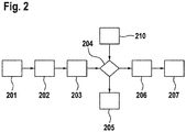
- the respective control unit 140 is also set up, in particular in terms of programming, to carry out a preferred embodiment of a method according to the invention, which Figure 2 is shown schematically as a block diagram and below with reference to FIG Figures 1 and 2nd is explained.
- a regular resistance welding process of the workpieces 120 is carried out with the welding devices 100, in the course of which the welding electrodes 111, 112 are first of all used with the aid of the electrode drive 130 Sheets 121 and 122 are pressed, then energized with the welding current and finally moved away from the workpieces 120 again with the aid of the electrode drive 130.
- a time profile of at least one drive parameter of the electrode drive 130 is determined in accordance with step 202, for example a time profile of an actual position value of one of the welding electrodes 111, 112.
- an actual position value of the electrode drive i. of the movable drive part (e.g. piston, slide, rotor, etc.).
- step 203 at least one characteristic value is determined from the time profile of the at least one drive parameter. For example, as such characteristic values, slopes of different areas of the time profile of the actual position value are determined.
- the time profile of the actual position value can be divided into different areas or sections, for example, so that the time profile in each of these areas is linear or at least substantially linear with a constant or at least substantially constant gradient.
- the respective slope is determined as a characteristic value in each of these sections.
- these sections correspond in particular to at least one force build-up phase, at least one lead phase, at least one current phase and at least one follow-up phase.
- each of these specific characteristic values that is to say each of the determined gradients, is compared with at least one reference value, in particular in each case with two reference values which specify a permissible value range for the respective gradient. It is thus checked in step 204 in particular whether the individual slopes determined in step 203 are each within a permissible value or tolerance range.
- a characteristic course of the actual position value during the welding process which has characteristic gradients in characteristic sections.
- the reference values in particular define value or tolerance ranges around these individual characteristic gradients, within which the corresponding gradients typically lie in a coaxially aligned welding gun 110.
- these reference values and thus the corresponding value ranges can be learned in the course of a reference welding process, which is carried out, for example, with the welding gun 110 on a defined reference workpiece.
- this reference welding process indicated by reference number 210, may have been carried out before the welding gun 110 is started up, or, for example, may also be repeated at regular time intervals during the regular operation of the welding gun 110.
- step 203 If the slopes determined in step 203 are each within their respective permissible value ranges, it is evaluated in step 205 that the welding electrodes 111, 112 are aligned coaxially.
- step 206 If, on the other hand, at least one of the slopes determined in step 203 is not within the respective permissible value range, it is evaluated in step 206 that the welding electrodes 111, 112 are not aligned coaxially. In this case, a predetermined measure is carried out in step 207, in particular readjustment of the welding gun 110.
- Figure 3 schematically shows a diagram of the actual position value s of the electrode drive 130 plotted against the time t.
- the curve 300 represents, for example, a time course of the actual position value in the case of coaxially aligned welding electrodes 111, 112.
- the slope of a compensation line 311 is determined as a first characteristic value.
- the first area 310 is the so-called lead phase, during which the welding electrodes 111, 112 are pressed against the welding points 125 of the workpieces 121, 122 with the electrode force before the welding process begins, but are not yet energized with the welding current.
- a second area 320 for example, the slope of a compensating line 321 is determined as a second characteristic value.
- the second area is the current phase during which the welding electrodes 111, 112 are supplied with the welding current for the duration of the welding time.
- the slopes of corresponding compensation lines 331 and 341 are determined as a third characteristic value and a fourth characteristic value.
- the so-called sustaining phase begins, during which the welding electrodes 111, 112 are still pressed with the electrode force against the welding point 125 of the workpieces 121, 122, but no longer with the Welding current.
- the third and fourth characteristic values are determined in the present example, the third characteristic value being the slope immediately after the end of the current supply and the fourth characteristic value being the slope after the connection has solidified.
- Figure 4 shows analog to Figure 3 schematically shows a diagram of the actual position value s of the electrode drive 130 plotted against the time t.
- Curve 400 represents, for example, a time course of the actual position value for non-coaxially aligned welding electrodes 111, 112.
- the slope of a compensating line 411 is determined as a first characteristic value in a first area 410, and the slope of a slope in a second area 420 Equalization line 421 as a second characteristic value, in a third area 430 the slope of an equalization line 431 as a third characteristic value and in a fourth area 440 the slope of an equalization line 441 as a fourth characteristic value.
- the time profile 300 of the actual position value of coaxially aligned welding electrodes differs significantly from the time comparison 400 of non-coaxially aligned welding electrodes.
- clearly different gradients occur in the current phase and in the sustaining phase, which makes it possible to clearly differentiate between the two states.
- the increase in the follow-up phase is also significantly flatter than in Figure 3 .
- the gradient of the straight line 321, that is to say the second characteristic value of the curve 300 is, for example, significantly greater in magnitude than the second characteristic value of the curve 400, that is to say the gradient of the Straight line 421.
- the third characteristic value of curve 300 has a positive sign, for example, since straight line 331 has a positive slope.
- the straight line 431 of curve 400 has a negative slope and accordingly the third characteristic value of curve 400 has a negative sign.
Landscapes
- Engineering & Computer Science (AREA)
- Mechanical Engineering (AREA)
- Resistance Welding (AREA)
Applications Claiming Priority (1)
| Application Number | Priority Date | Filing Date | Title |
|---|---|---|---|
| DE102019200199.8A DE102019200199A1 (de) | 2019-01-10 | 2019-01-10 | Verfahren zum Überprüfen einer Schweißzange zum Widerstandsschweißen von Werkstücken |
Publications (2)
| Publication Number | Publication Date |
|---|---|
| EP3680050A2 true EP3680050A2 (fr) | 2020-07-15 |
| EP3680050A3 EP3680050A3 (fr) | 2020-07-22 |
Family
ID=68426239
Family Applications (1)
| Application Number | Title | Priority Date | Filing Date |
|---|---|---|---|
| EP19206802.1A Withdrawn EP3680050A3 (fr) | 2019-01-10 | 2019-11-04 | Procédé de vérification d'une pince à souder permettant le soudage par résistance de pièces à usiner |
Country Status (3)
| Country | Link |
|---|---|
| EP (1) | EP3680050A3 (fr) |
| CN (1) | CN111421212B (fr) |
| DE (1) | DE102019200199A1 (fr) |
Families Citing this family (3)
| Publication number | Priority date | Publication date | Assignee | Title |
|---|---|---|---|---|
| CN111702310B (zh) * | 2020-06-17 | 2022-07-22 | 一汽奔腾轿车有限公司 | 一种综合评估电阻点焊焊钳电极对中状态的方法 |
| CN112775528B (zh) * | 2020-12-22 | 2022-09-27 | 上海电力大学 | 一种自动评估电阻点焊钳刚性的方法 |
| CN114535763A (zh) * | 2022-04-02 | 2022-05-27 | 安徽日基焊接装备有限公司 | 一种c型间接焊钳 |
Family Cites Families (10)
| Publication number | Priority date | Publication date | Assignee | Title |
|---|---|---|---|---|
| US5412172A (en) * | 1990-10-08 | 1995-05-02 | Kabushiki Kaisha Sg | Spot welding machine |
| DE102006038786A1 (de) * | 2006-08-18 | 2008-02-21 | Robert Bosch Gmbh | Steuerung einer Schweißvorrichtung |
| DE102012021766B4 (de) * | 2012-11-06 | 2022-03-24 | Audi Ag | Schweißanordnung insbesondere für den Karosseriebau |
| EP2965848B1 (fr) * | 2013-03-08 | 2019-08-14 | JFE Steel Corporation | Procédé de soudage par points par résistance |
| KR101584495B1 (ko) * | 2013-03-29 | 2016-01-13 | 제이에프이 스틸 가부시키가이샤 | 저항 스폿 용접 시스템 |
| DE102015111459B4 (de) * | 2015-07-15 | 2017-08-03 | Nimak Gmbh | "Qualitätsüberwachung einer Schweißverbindung" |
| CN105033435B (zh) * | 2015-08-14 | 2017-05-31 | 数码模冲压技术(武汉)有限公司 | 一种固定点焊机电极臂快速对中的结构及方法 |
| CN107552935B (zh) * | 2017-07-24 | 2020-04-24 | 中国铁道科学研究院金属及化学研究所 | 一种固定式钢轨闪光焊接自动对中及测量装置 |
| CN108971722A (zh) * | 2018-07-17 | 2018-12-11 | 上海空间推进研究所 | 精确控制箍带电阻点焊过程特性和接头质量的工艺方法 |
| DE102018217364A1 (de) * | 2018-10-11 | 2020-04-16 | Robert Bosch Gmbh | Verfahren zum Überprüfen der Qualität bei einem Widerstandsschweißen von Werkstücken |
-
2019
- 2019-01-10 DE DE102019200199.8A patent/DE102019200199A1/de not_active Withdrawn
- 2019-11-04 EP EP19206802.1A patent/EP3680050A3/fr not_active Withdrawn
-
2020
- 2020-01-09 CN CN202010022902.0A patent/CN111421212B/zh active Active
Also Published As
| Publication number | Publication date |
|---|---|
| EP3680050A3 (fr) | 2020-07-22 |
| CN111421212A (zh) | 2020-07-17 |
| CN111421212B (zh) | 2023-06-27 |
| DE102019200199A1 (de) | 2020-07-16 |
Similar Documents
| Publication | Publication Date | Title |
|---|---|---|
| DE102017119242B4 (de) | Vorrichtung zum Punktschweißen, die den Schweißzustand beurteilt | |
| EP3639962A1 (fr) | Procédé de vérification de la qualité pendant le soudage par résistance de deux pièces | |
| DE102016107398B4 (de) | Qualitätskontrollsystem für punktschweissen | |
| DE202011000875U1 (de) | Kontrolleinrichtung | |
| EP3895834B1 (fr) | Procédé et unité de commande destiné au soudage par résistance | |
| DE102019200199A1 (de) | Verfahren zum Überprüfen einer Schweißzange zum Widerstandsschweißen von Werkstücken | |
| DE102015225050A1 (de) | Verfahren zum Erstellen einer Datenbank zur Durchführung von Schweißprozessen | |
| EP3639963B1 (fr) | Dispositif et procédé de fonctionnement d'un dispositif de soudage par résistance | |
| EP3895835B1 (fr) | Procédé de soudage par résistance | |
| DE102006038786A1 (de) | Steuerung einer Schweißvorrichtung | |
| DE102013216966A1 (de) | Erkennen von Schweißspritzern durch Widerstandsmessung | |
| EP4063057B1 (fr) | Procédé de soudage par résistance de pièces | |
| DE102016211684A1 (de) | Erkennen von anlegierten Elektrodenkappen beim Widerstandsschweißen | |
| EP3760360B1 (fr) | Commande de soudage pour un outil de soudage et procédé permettant d'éviter des vibrations de force d'un outil de soudage | |
| DE102016209640A1 (de) | Verfahren zum Kalibrieren einer Schweißzange zum Widerstandschweißen | |
| EP3636377A1 (fr) | Procédé de soudage par résistance de pièces | |
| DE102008038332A1 (de) | Verfahren und Vorrichtung zur Regelung eines Schweißprozesses | |
| DE102015215190A1 (de) | Verfahren und Vorrichtung zum Durchführen eines Schweißprozesses | |
| DE102013217583A1 (de) | Bewerten eines Widerstandsschweißvorgangs durch Elektrodenkraftüberwachung | |
| EP3808492A1 (fr) | Procédé de vérification de la qualité de la soudure par résistance de pièces | |
| EP3760359B1 (fr) | Commande de soudage pour un outil de soudage, installation de soudage, et procédé de régulation de la force d'un outil de soudage | |
| EP3124160B1 (fr) | Procede adaptatif destine au fraisage des electrodes de dispositifs de soudage par points | |
| DE102019215887A1 (de) | Verfahren zum Widerstandsschweißen von Werkstücken | |
| DE102015221468A1 (de) | Verfahren zum Durchführen eines Schweißprozesses von an einem Schweißpunkt miteinander zu verschweißenden Werkstücken | |
| DE102017215105A1 (de) | Verfahren zum Durchführen von Schweißprozessen von an einem Schweißpunkt miteinander zu verschweißenden Werkstücken |
Legal Events
| Date | Code | Title | Description |
|---|---|---|---|
| PUAI | Public reference made under article 153(3) epc to a published international application that has entered the european phase |
Free format text: ORIGINAL CODE: 0009012 |
|
| STAA | Information on the status of an ep patent application or granted ep patent |
Free format text: STATUS: THE APPLICATION HAS BEEN PUBLISHED |
|
| PUAL | Search report despatched |
Free format text: ORIGINAL CODE: 0009013 |
|
| AK | Designated contracting states |
Kind code of ref document: A2 Designated state(s): AL AT BE BG CH CY CZ DE DK EE ES FI FR GB GR HR HU IE IS IT LI LT LU LV MC MK MT NL NO PL PT RO RS SE SI SK SM TR |
|
| AX | Request for extension of the european patent |
Extension state: BA ME |
|
| AK | Designated contracting states |
Kind code of ref document: A3 Designated state(s): AL AT BE BG CH CY CZ DE DK EE ES FI FR GB GR HR HU IE IS IT LI LT LU LV MC MK MT NL NO PL PT RO RS SE SI SK SM TR |
|
| AX | Request for extension of the european patent |
Extension state: BA ME |
|
| RIC1 | Information provided on ipc code assigned before grant |
Ipc: B23K 11/11 20060101AFI20200615BHEP Ipc: B23K 11/25 20060101ALI20200615BHEP |
|
| STAA | Information on the status of an ep patent application or granted ep patent |
Free format text: STATUS: THE APPLICATION IS DEEMED TO BE WITHDRAWN |
|
| 18D | Application deemed to be withdrawn |
Effective date: 20210122 |