EP3640123B1 - Structure de support de cadre dotée d'un récipient de collecte pour au moins un composant de véhicule utilitaire - Google Patents
Structure de support de cadre dotée d'un récipient de collecte pour au moins un composant de véhicule utilitaire Download PDFInfo
- Publication number
- EP3640123B1 EP3640123B1 EP19214480.6A EP19214480A EP3640123B1 EP 3640123 B1 EP3640123 B1 EP 3640123B1 EP 19214480 A EP19214480 A EP 19214480A EP 3640123 B1 EP3640123 B1 EP 3640123B1
- Authority
- EP
- European Patent Office
- Prior art keywords
- receiving container
- bearing structure
- frame load
- crossmember
- cross member
- Prior art date
- Legal status (The legal status is an assumption and is not a legal conclusion. Google has not performed a legal analysis and makes no representation as to the accuracy of the status listed.)
- Active
Links
Images


Classifications
-
- B—PERFORMING OPERATIONS; TRANSPORTING
- B62—LAND VEHICLES FOR TRAVELLING OTHERWISE THAN ON RAILS
- B62D—MOTOR VEHICLES; TRAILERS
- B62D21/00—Understructures, i.e. chassis frame on which a vehicle body may be mounted
- B62D21/02—Understructures, i.e. chassis frame on which a vehicle body may be mounted comprising longitudinally or transversely arranged frame members
-
- B—PERFORMING OPERATIONS; TRANSPORTING
- B60—VEHICLES IN GENERAL
- B60R—VEHICLES, VEHICLE FITTINGS, OR VEHICLE PARTS, NOT OTHERWISE PROVIDED FOR
- B60R19/00—Wheel guards; Radiator guards, e.g. grilles; Obstruction removers; Fittings damping bouncing force in collisions
- B60R19/02—Bumpers, i.e. impact receiving or absorbing members for protecting vehicles or fending off blows from other vehicles or objects
- B60R19/48—Bumpers, i.e. impact receiving or absorbing members for protecting vehicles or fending off blows from other vehicles or objects combined with, or convertible into, other devices or objects, e.g. bumpers combined with road brushes, bumpers convertible into beds
-
- B—PERFORMING OPERATIONS; TRANSPORTING
- B60—VEHICLES IN GENERAL
- B60K—ARRANGEMENT OR MOUNTING OF PROPULSION UNITS OR OF TRANSMISSIONS IN VEHICLES; ARRANGEMENT OR MOUNTING OF PLURAL DIVERSE PRIME-MOVERS IN VEHICLES; AUXILIARY DRIVES FOR VEHICLES; INSTRUMENTATION OR DASHBOARDS FOR VEHICLES; ARRANGEMENTS IN CONNECTION WITH COOLING, AIR INTAKE, GAS EXHAUST OR FUEL SUPPLY OF PROPULSION UNITS IN VEHICLES
- B60K1/00—Arrangement or mounting of electrical propulsion units
- B60K1/04—Arrangement or mounting of electrical propulsion units of the electric storage means for propulsion
-
- B—PERFORMING OPERATIONS; TRANSPORTING
- B60—VEHICLES IN GENERAL
- B60K—ARRANGEMENT OR MOUNTING OF PROPULSION UNITS OR OF TRANSMISSIONS IN VEHICLES; ARRANGEMENT OR MOUNTING OF PLURAL DIVERSE PRIME-MOVERS IN VEHICLES; AUXILIARY DRIVES FOR VEHICLES; INSTRUMENTATION OR DASHBOARDS FOR VEHICLES; ARRANGEMENTS IN CONNECTION WITH COOLING, AIR INTAKE, GAS EXHAUST OR FUEL SUPPLY OF PROPULSION UNITS IN VEHICLES
- B60K11/00—Arrangement in connection with cooling of propulsion units
- B60K11/02—Arrangement in connection with cooling of propulsion units with liquid cooling
- B60K11/04—Arrangement or mounting of radiators, radiator shutters, or radiator blinds
-
- B—PERFORMING OPERATIONS; TRANSPORTING
- B60—VEHICLES IN GENERAL
- B60K—ARRANGEMENT OR MOUNTING OF PROPULSION UNITS OR OF TRANSMISSIONS IN VEHICLES; ARRANGEMENT OR MOUNTING OF PLURAL DIVERSE PRIME-MOVERS IN VEHICLES; AUXILIARY DRIVES FOR VEHICLES; INSTRUMENTATION OR DASHBOARDS FOR VEHICLES; ARRANGEMENTS IN CONNECTION WITH COOLING, AIR INTAKE, GAS EXHAUST OR FUEL SUPPLY OF PROPULSION UNITS IN VEHICLES
- B60K1/00—Arrangement or mounting of electrical propulsion units
- B60K2001/003—Arrangement or mounting of electrical propulsion units with means for cooling the electrical propulsion units
- B60K2001/005—Arrangement or mounting of electrical propulsion units with means for cooling the electrical propulsion units the electric storage means
-
- B—PERFORMING OPERATIONS; TRANSPORTING
- B60—VEHICLES IN GENERAL
- B60K—ARRANGEMENT OR MOUNTING OF PROPULSION UNITS OR OF TRANSMISSIONS IN VEHICLES; ARRANGEMENT OR MOUNTING OF PLURAL DIVERSE PRIME-MOVERS IN VEHICLES; AUXILIARY DRIVES FOR VEHICLES; INSTRUMENTATION OR DASHBOARDS FOR VEHICLES; ARRANGEMENTS IN CONNECTION WITH COOLING, AIR INTAKE, GAS EXHAUST OR FUEL SUPPLY OF PROPULSION UNITS IN VEHICLES
- B60K1/00—Arrangement or mounting of electrical propulsion units
- B60K1/04—Arrangement or mounting of electrical propulsion units of the electric storage means for propulsion
- B60K2001/0405—Arrangement or mounting of electrical propulsion units of the electric storage means for propulsion characterised by their position
- B60K2001/0416—Arrangement in the rear part of the vehicle
-
- B—PERFORMING OPERATIONS; TRANSPORTING
- B60—VEHICLES IN GENERAL
- B60K—ARRANGEMENT OR MOUNTING OF PROPULSION UNITS OR OF TRANSMISSIONS IN VEHICLES; ARRANGEMENT OR MOUNTING OF PLURAL DIVERSE PRIME-MOVERS IN VEHICLES; AUXILIARY DRIVES FOR VEHICLES; INSTRUMENTATION OR DASHBOARDS FOR VEHICLES; ARRANGEMENTS IN CONNECTION WITH COOLING, AIR INTAKE, GAS EXHAUST OR FUEL SUPPLY OF PROPULSION UNITS IN VEHICLES
- B60K1/00—Arrangement or mounting of electrical propulsion units
- B60K1/04—Arrangement or mounting of electrical propulsion units of the electric storage means for propulsion
- B60K2001/0405—Arrangement or mounting of electrical propulsion units of the electric storage means for propulsion characterised by their position
- B60K2001/0438—Arrangement under the floor
-
- B—PERFORMING OPERATIONS; TRANSPORTING
- B60—VEHICLES IN GENERAL
- B60Y—INDEXING SCHEME RELATING TO ASPECTS CROSS-CUTTING VEHICLE TECHNOLOGY
- B60Y2200/00—Type of vehicle
- B60Y2200/10—Road Vehicles
- B60Y2200/14—Trucks; Load vehicles, Busses
-
- B—PERFORMING OPERATIONS; TRANSPORTING
- B60—VEHICLES IN GENERAL
- B60Y—INDEXING SCHEME RELATING TO ASPECTS CROSS-CUTTING VEHICLE TECHNOLOGY
- B60Y2200/00—Type of vehicle
- B60Y2200/10—Road Vehicles
- B60Y2200/14—Trucks; Load vehicles, Busses
- B60Y2200/145—Haulage vehicles, trailing trucks
-
- B—PERFORMING OPERATIONS; TRANSPORTING
- B60—VEHICLES IN GENERAL
- B60Y—INDEXING SCHEME RELATING TO ASPECTS CROSS-CUTTING VEHICLE TECHNOLOGY
- B60Y2200/00—Type of vehicle
- B60Y2200/10—Road Vehicles
- B60Y2200/14—Trucks; Load vehicles, Busses
- B60Y2200/148—Semi-trailers, articulated vehicles
-
- B—PERFORMING OPERATIONS; TRANSPORTING
- B60—VEHICLES IN GENERAL
- B60Y—INDEXING SCHEME RELATING TO ASPECTS CROSS-CUTTING VEHICLE TECHNOLOGY
- B60Y2306/00—Other features of vehicle sub-units
- B60Y2306/01—Reducing damages in case of crash, e.g. by improving battery protection
-
- B—PERFORMING OPERATIONS; TRANSPORTING
- B60—VEHICLES IN GENERAL
- B60Y—INDEXING SCHEME RELATING TO ASPECTS CROSS-CUTTING VEHICLE TECHNOLOGY
- B60Y2410/00—Constructional features of vehicle sub-units
- B60Y2410/10—Housings
Definitions
- the invention relates to a frame support structure, in particular a chassis, for a commercial vehicle, preferably a truck, in particular a tractor unit, with a receiving container for at least one commercial vehicle component.
- a chassis frame which comprises two longitudinal beams, at least a first and a second cross beam between the two longitudinal beams, and a battery box which is arranged at the rear end of the vehicle between the beams with vibration damping fastening means.
- the fastening means of the battery box comprises front fastening means for connecting the front of the battery box to the first adjacent cross beam and rear fastening means for connecting the rear of the battery box to the second adjacent cross beam.
- a commercial vehicle in particular a tractor unit, with at least one electric motor by means of which the commercial vehicle can be driven, with at least one electrical storage device for storing electrical energy, by means of which the electric motor can be supplied with the electrical energy to drive the commercial vehicle, and with a frame which comprises at least two longitudinal support elements which are spaced apart from one another in the transverse direction of the vehicle and connected to one another, wherein the electrical storage device is arranged between the longitudinal support elements in the transverse direction of the vehicle and is arranged behind the rearmost rear axle of the commercial vehicle.
- the frame support structure comprises two longitudinal members, which are spaced apart from one another in the transverse direction of the frame support structure, and several cross members, which connect the longitudinal members to one another.
- the frame support structure comprises a receiving box for a high-voltage battery, which is attached to the outside of one of the longitudinal members and at the same time in front of a rear axle of the truck.
- mounting the support box on the outside of the side member results in off-center loading of the same, which can be disadvantageous, particularly when the truck is driving and the associated vibration excitation.
- An object of the invention is to provide an alternative and/or improved frame support structure for a commercial vehicle with a receiving container, in particular to provide an alternative installation space for the receiving container.
- a frame support structure preferably a chassis, is created for a commercial vehicle, in particular a truck (e.g. a tractor unit, a distribution truck, etc.).
- the frame support structure comprises at least one receptacle for at least one commercial vehicle component (e.g. a hybrid component for the commercial vehicle, a battery, a high-voltage battery for a hybrid drive of the commercial vehicle, a starter battery, etc.), two longitudinal support structures which are expediently spaced apart from one another in the transverse direction of the frame support structure, a rear axle for the commercial vehicle, and an end cross member which is expediently arranged behind the rear axle for the commercial vehicle and/or via which the two longitudinal support structures are preferably connected to one another.
- the frame support structure can be provided with a front axle.
- the frame support structure according to the invention is characterized in particular by that the receptacle is arranged behind the rear axle and thus makes practical use of the installation space behind the rear axle. This means that the installation space in front of the rear axle can be used for other purposes. In addition, for example, a favorable axle load distribution and/or easy access to a starter battery mounted on the frame support structure can be made possible.
- the receptacle preferably serves to accommodate one or more hybrid components for the commercial vehicle (e.g. a battery, a high-voltage battery, a battery system made up of several storage modules, together with associated electronic components, a secondary cooling circuit (e.g. water pump, radiator and/or fan), an on-board network charging converter and/or power electronics) in order to expediently form a hybrid module.
- the receptacle itself can be provided, for example, as a receptacle housing, a grid-frame-shaped or solid-walled receptacle or in the form of another suitable receptacle/support structure.
- the receiving container is arranged at least in sections along the end cross member.
- the receiving container can also be arranged at least in sections along at least one of the two longitudinal member structures (e.g. laterally outside, laterally inside, on top of and/or underneath).
- the receiving container is arranged at least in sections under the end cross member, namely under its underside.
- the receiving container can also be arranged at least in sections above the end cross member (in particular above its upper side).
- the receiving container is arranged at least in sections in front of the front of the end cross member or at least in sections in front of the rear of the end cross member.
- the receiving container can also be arranged so that it runs completely in front of the rear of the end cross member and thus does not extend backwards beyond the rear of the end cross member.
- the receiving container can even be arranged so that it runs completely in front of the front of the end cross member and thus does not extend backwards beyond the front of the end cross member.
- the receptacle can even be arranged at least partially within the end cross member.
- the end cross member can, for example, be designed to be essentially U-shaped.
- the embodiments in which the receiving container is preferably arranged completely in front of the rear side and/or in front of the front side of the end cross member have the particular advantage that the end cross member itself can serve as a crash protection structure for the receiving container.
- the invention also includes embodiments in which the frame support structure is provided with an additional crash protection structure that protects the receptacle from an impact.
- the crash protection structure comprises a cross member element which extends in the transverse direction of the frame support structure, runs behind the receiving container and is arranged at least in sections below the level of the end cross member.
- the crash protection structure can comprise, in addition to the cross member element, two side elements which serve as side impact protection for the receptacle and, together with the cross member element, form a substantially U-shaped configuration.
- the receptacle prefferably connected to the end cross member and/or at least one of the two longitudinal member structures via at least one damping element.
- the damping element serves to reduce vibration and/or impact stress on the receptacle while the commercial vehicle is driving.
- the receiving container is mounted on the underside of the end cross member.
- the longitudinal beam structures are extended to the rear in order to create space for the receptacle, in particular behind the rear axle and in front of the end cross member.
- the end cross member is conveniently each of its two side ends is provided with a side arm construction which can serve as part, in particular as an extension, of the longitudinal support structures.
- the side arm structures protrude forwards from the cross member and are also connected to the two longitudinal support structures in order to expediently act as extensions of the two longitudinal support structures.
- the side arm structures protrude rearwards from the cross member and are connected to the cross member element of the crash protection structure in order to expediently act as part of the crash protection structure.
- the receiving container extends in sections laterally outside and preferably laterally inside the two longitudinal support structures and at the same time runs, for example, under them.
- the receiving container prefferably be designed and arranged in such a way that its own weight is transferred, e.g. directly or indirectly, to the two longitudinal support structures in essentially equal parts. This can prevent one-sided (e.g. unequal) loading of the frame support structure, in particular the two longitudinal support structures.
- the receiving container can extend at least over the entire longitudinal extent of the end cross member and thus expediently be at least as long as the end cross member.
- the final cross member is provided with side arm structures that are connected to the longitudinal beam structures and serve as an extension of the longitudinal beam structures and the end cross member, the side arm structures and the crash protection structure form a structural unit.
- the longitudinal beam structures are designed as U-profile beams, for example, but can also be designed as I-profile beams, hollow profile beams, L-profile beams or as sheet metal structures or in the form of other suitable support structures.
- the respective longitudinal beam structure can be made from a single support element or several interconnected (e.g. welded, screwed, riveted, etc.) support elements.
- the end cross member can be designed as a conventional U-profile beam, L-profile beam, I-profile beam or hollow profile beam, for example, or as a sheet metal structure or in the form of another suitable support structure.
- the features “in front” and “behind” are preferably to be understood as defining a positioning in the longitudinal direction of the frame support structure or the commercial vehicle, while a positioning in the vertical and/or transverse direction of the frame support structure or the commercial vehicle is not restricted unless a positioning in the vertical and/or transverse direction is expressly specified.
- the features “in front” expediently refer to the front side and the features “behind” to the rear side of the frame support structure or the commercial vehicle.
- the frame support structure can be equipped with a single rear axle or several rear axles (e.g. a double or tandem rear axle arrangement), which can, for example, be equipped with single or twin tires.
- the receiving container within the scope of the invention is not limited to a single receiving container, but can also comprise several separate receiving containers.
- the invention also includes a commercial vehicle, preferably a truck, in particular a tractor unit or a distribution truck, with a frame support structure as described herein.
- a commercial vehicle preferably a truck, in particular a tractor unit or a distribution truck, with a frame support structure as described herein.
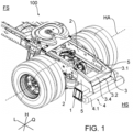
- Figure 1 shows a perspective view of a part of a frame support structure 100 in the form of a chassis for a commercial vehicle, in particular a tractor unit.
- Reference symbol L indicates the longitudinal direction, reference symbol H the vertical direction and reference symbol Q the transverse direction of the frame support structure 100 and thus of the commercial vehicle.
- Reference symbol FS indicates the front side and reference symbol HS the rear side of the frame support structure 100 and thus of the commercial vehicle.
- “Front/Front” and “Rear/Behind” refer to the longitudinal direction L.
- “Front/Front” refers to the front side FS and “Rear/Behind” to the rear side HS.
- Below/Above refers to the vertical direction H.
- the frame support structure 100 is equipped with a receptacle 1 for one or more hybrid components, e.g. a battery, in particular a high-voltage battery, associated electronic components, an on-board network charging converter, power electronics, etc.
- the receptacle 1 thus represents a hybrid module.
- the frame support structure 100 is also provided with a Figure 1 not visible front axle and a rear axle HA for the commercial vehicle.
- the frame support structure 100 comprises two spaced-apart longitudinal beam structures 2 and a final cross member 3, which has a front side 3.1, a rear side 3.2, a Figure 1 has an invisible bottom side 3.3 and a top side 3.4.
- the receiving container 1 is arranged behind the rear axle HA and extends in sections along and under the end cross member 3. In addition, the receiving container 1 is designed and arranged such that it does not extend rearward beyond the rear side 3.2 of the end cross member 3 and thus runs completely in front of the rear side 3.2 of the end cross member 3.
- the frame support structure 100 is also provided with a crash protection structure 4 that protects the receptacle 1 from an impact.
- the crash protection structure 4 comprises in particular a cross member element 4.1 that extends in the transverse direction Q of the frame support structure 100, runs behind the receptacle 1 and is arranged at least in sections below the level of the end cross member 3.
- the cross member element 4.1 is designed to be longer than the receptacle 1 to form an overhang, whereby it can also serve as side impact protection for the receptacle 1.
- the crash protection structure 4 can also comprise two side elements (not shown) that can enclose the receptacle 1 at the side as additional side impact protection.
- the cross member element 4.1 and the two side elements can, for example, form a substantially U-shaped configuration in order to border the receptacle 1 on three sides.
- Figure 1 also shows that the two longitudinal beam structures 2 are extended rearward in order to create installation space for the receiving container 1 behind the rear axle HA and in front of the end cross member 3.
- the end cross member 3 can be provided at each of its two side ends with a side arm structure 5, which can be considered as part and in particular as an extension of the two longitudinal beam structures 2.
- the two side arm structures 5 protrude forward from the cross member 3 to act as extensions of the two longitudinal member structures 2, thereby creating installation space for the receptacle 1. At the same time, the two side arm structures 5 protrude rearward from the cross member 3 and are connected to the cross member element 4.1 in order to be able to act as part of the crash protection structure 4.
- the final cross member 3, the two side arm structures 5 and the crash protection structure 4 form a structural unit which can preferably be mounted as a whole at the rear of the two longitudinal member structures 2 and, if necessary, dismantled.
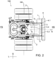
- Figure 2 shows a top view of the frame support structure 100 of the Figure 1 .
- Figure 2 In particular, it can be seen that the receptacle 1 is located behind the rear axle HA, in sections in front of the front side 3.1 of the end cross member 3, in sections behind the front side 3.1 of the end cross member 3 and under the end cross member 3 and at the same time extends entirely in front of the rear side 3.2 of the end cross member 3.
- Figure 2 It can be seen that the receiving container 1 is designed and arranged in such a way that its own weight is transferred to the two longitudinal support structures 2 in essentially equal parts via the end cross member 3 and the side arm structures 5, whereby a one-sided, unequal loading of the two longitudinal support structures 2 can be avoided.
- Figure 2 It can be seen that the receiving container 1 is arranged in sections laterally outside and in sections laterally inside the two side arm structures 5 or generally the two longitudinal member structures 2 and extends over the entire longitudinal extent of the end cross member 3.
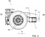
- Figure 3 shows a side view of a part of the frame support structure 100 of the Figures 1 and 2 . It can be seen, for example, that the receiving container 1 is arranged under the end cross member 3 which is concealed by a side arm construction 5 and is mounted on the underside 3.3 of the end cross member 3. Figure 3 It can also be seen that the longitudinal member structures 2 extended to the rear create installation space between the rear axle HA and the end cross member 3 for the receiving container 1.
- Figure 4 is a rear view of the frame support structure 100 of the Figures 1-3 .
- Figure 4 In particular, it can be seen that the receiving container 1 extends along the end cross member 3 and at the same time laterally outside the two longitudinal member structures 2 and is thus longer than the end cross member 3, but shorter than the cross member element 4.1 of the crash protection structure 4.
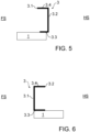
- Figure 5 shows a schematic cross-sectional view along line AA of Figure 2 a final cross member 3 having a front side 3.1, a rear side 3.2, a bottom side 3.3 and a top side 3.4 and a receiving container 1 according to an embodiment of the invention.
- Figure 5 shows an embodiment in which the receiving container 1 is arranged behind the rear axle HA, under the end cross member 3, in front of and behind the front side 3.1 of the end cross member 3 and completely in front of the rear side 3.2 of the end cross member 3.
- Figure 6 shows a schematic cross-sectional view along line AA of Figure 2 a final cross member 3 having a front side 3.1, a rear side 3.2, a bottom side 3.3 and a top side 3.4 and a receiving container 1 according to another embodiment of the invention.
- Figure 6 shows an embodiment in which the receiving container 1 is arranged behind the rear axle HA, under the end cross member 3, behind the front side 3.1 of the end cross member 3 and even behind the rear side 3.2 of the end cross member 3.
- Figure 7 shows a schematic cross-sectional view along line AA of Figure 2 a final cross member 3 having a front side 3.1, a rear side 3.2, a bottom side 3.3 and a top side 3.4 and a receiving container 1 according to yet another embodiment of the invention.
- Figure 7 shows an embodiment in which the receiving container 1 is arranged behind the rear axle HA, within the end cross member 3, in front of and behind the front side 3.1 of the end cross member 3 and also completely in front of the rear side 3.2 of the end cross member 3.
- Figure 8 shows a schematic cross-sectional view along line AA of Figure 2 a final cross member 3 having a front side 3.1, a rear side 3.2, a bottom side 3.3 and a top side 3.4 and a receiving container 1 according to another embodiment of the invention.
- Figure 8 shows an embodiment in which the receiving container 1 is arranged behind the rear axle HA, behind the front side 3.1 of the end cross member 3, completely in front of the rear side 3.2 of the end cross member 3 and also above and below the end cross member 3.
- Figure 9 shows a schematic cross-sectional view along line AA of Figure 2 a final cross member 3 having a front side 3.1, a rear side 3.2, a bottom side 3.3 and a top side 3.4 and a receiving container 1 according to yet another embodiment of the invention.
- Figure 9 shows an embodiment in which the receiving container 1 is arranged behind the rear axle HA and completely behind the rear side 3.2 of the end cross member 3.
- the receptacle 1 is exposed to the rear without protection and there is a risk that in the event of a crash of the commercial vehicle, the receptacle 1 cannot adequately protect the hybrid components it contains, which is why a crash protection structure 4
- the crash protection structure 4 can also be used if required in the Figures 5 , 7 and 8 shown embodiments are used.
- the receptacle 1 serves to accommodate a starter battery and, for example, a high-voltage battery.
- the high-voltage battery is expediently a hybrid battery that serves as an energy storage device for a hybrid drive of the commercial vehicle.
- the installation space behind the rear axle HA and along at least one of the longitudinal member structures 2 can also be used for at least one receiving container 1.
- the invention also includes embodiments with several, quasi separate receptacles 1, which can be arranged at a distance from one another, for example.
- one receptacle 1 can be arranged on one longitudinal support structure 2, one receptacle 1 on the other longitudinal support structure 2 and, alternatively or additionally, one receptacle 1 on the end cross member 3.
Landscapes
- Engineering & Computer Science (AREA)
- Mechanical Engineering (AREA)
- Chemical & Material Sciences (AREA)
- Combustion & Propulsion (AREA)
- Transportation (AREA)
- Body Structure For Vehicles (AREA)
- Cooling, Air Intake And Gas Exhaust, And Fuel Tank Arrangements In Propulsion Units (AREA)
- Arrangement Or Mounting Of Propulsion Units For Vehicles (AREA)
Claims (16)
- Structure porteuse de cadre (100), de préférence châssis, pour un véhicule utilitaire, de préférence un camion, comprenant- au moins un réceptacle (1) pour au moins un composant de véhicule utilitaire, de préférence au moins un composant hybride pour le véhicule utilitaire,- deux constructions de longerons (2),- au moins un essieu arrière (HA) pour le véhicule utilitaire, et- une traverse terminale (3) qui est disposée de préférence derrière l'essieu arrière (HA)
dans laquelle- le réceptacle (1) est disposé derrière l'essieu arrière (HA) et reçoit une batterie de démarrage,caractérisée en ce quele réceptacle (1) est disposé au moins par endroits sous la traverse terminale (3), notamment sous la face inférieure (3.3) de celle-ci, etle réceptacle (1) est disposé au moins par endroits latéralement à l'extérieur des deux constructions de longerons (2), et dans lequella structure porteuse de cadre (100) est munie d'un dispositif anticollision (4) protégeant le réceptacle (1) d'un choc, le dispositif anticollision (4) comprenant un élément de traverse (4.1) qui s'étend dans la direction transversale (Q) de la structure porteuse de cadre (100), passe derrière le réceptacle (1) et est disposé au moins par endroits au-dessous du niveau de la traverse terminale (3). - Structure porteuse de cadre (100) selon la revendication 1, caractérisée en ce que le réceptacle (1) est disposé au moins par endroits le long de la traverse terminale (3).
- Structure porteuse de cadre (100) selon la revendication 1 ou 2, caractérisée en ce que le réceptacle (1) est disposé au moins par endroits le long d'au moins l'une des deux constructions de longerons (2).
- Structure porteuse de cadre (100) selon l'une quelconque des revendications précédentes, caractérisée en ce que le réceptacle (1) est disposé au moins par endroits sous et/ou sur la traverse terminale (3).
- Structure porteuse de cadre (100) selon l'une quelconque des revendications précédentes, caractérisée en ce que le réceptacle (1) est disposé au moins par endroits devant la face avant (3.1) de la traverse terminale (3) ou au moins par endroits devant la face arrière (3.2) de la traverse terminale (3).
- Structure porteuse de cadre (100) selon l'une quelconque des revendications précédentes, caractérisée en ce que le réceptacle (1) est disposé entièrement devant la face avant (3.1) ou entièrement devant la face arrière (3.2) de la traverse terminale (3).
- Structure porteuse de cadre (100) selon l'une quelconque des revendications précédentes, caractérisée en ce que le réceptacle (1) est disposé au moins par endroits à l'intérieur de la traverse terminale (3).
- Structure porteuse de cadre (100) selon l'une quelconque des revendications précédentes, caractérisée en ce que le dispositif anticollision (4) comprend en plus de l'élément de traverse (4.1) deux éléments latéraux servant de dispositif anticollision latéral pour le réceptacle (1) et formant avec l'élément de traverse (4.1) une configuration substantiellement en forme de U.
- Structure porteuse de cadre (100) selon l'une quelconque des revendications précédentes, caractérisée en ce que le réceptacle (1) est relié par l'intermédiaire d'un élément d'amortissement à la traverse terminale (3) et/ou à au moins l'une des deux constructions de longerons (2).
- Structure porteuse de cadre (100) selon l'une quelconque des revendications précédentes, caractérisée en ce que le réceptacle (1) est monté sur la face inférieure (3.3) de la traverse terminale (3).
- Structure porteuse de cadre (100) selon l'une quelconque des revendications précédentes, caractérisée en ce que les deux constructions de longerons (2) sont prolongées vers l'arrière afin de ménager un espace de montage pour le réceptacle (1) derrière l'essieu arrière (HA) et devant la traverse terminale (3).
- Structure porteuse de cadre (100) selon l'une quelconque des revendications précédentes, caractérisée en ce que le réceptacle (1) est disposé au moins par endroits latéralement à l'intérieur des deux constructions de longerons (2).
- Structure porteuse de cadre (100) selon l'une quelconque des revendications précédentes, caractérisée en ce que le réceptacle (1) est réalisé et disposé de telle sorte que son poids propre soit réparti substantiellement à parts égales sur les deux constructions de longerons (2).
- Structure porteuse de cadre (100) selon l'une quelconque des revendications précédentes, caractérisée en ce que le réceptacle (1) s'étend au moins sur toute l'étendue longitudinale de la traverse terminale (3).
- Structure porteuse de cadre (100) selon l'une quelconque des revendications précédentes, caractérisée en ce que la traverse terminale (3) est munie de deux constructions de bras latéraux (5) qui sont reliées aux deux constructions de longerons (2) et servent de prolongement aux constructions de longerons (2), et la traverse terminale (3), les constructions de bras latéraux (5) et le dispositif anticollision (4) constituent une unité modulaire.
- Véhicule utilitaire, de préférence camion, en particulier tracteur de semi-remorque avec une structure porteuse de cadre (100) selon l'une quelconque des revendications précédentes.
Applications Claiming Priority (2)
| Application Number | Priority Date | Filing Date | Title |
|---|---|---|---|
| DE102012019023.9A DE102012019023A1 (de) | 2012-09-26 | 2012-09-26 | Rahmentragstruktur mit einem Aufnahmebehältnis für zumindest eine Nutzfahrzeugkomponente |
| EP13002063.9A EP2712788B1 (fr) | 2012-09-26 | 2013-04-19 | Châssis de véhicule utilitaire doté d'une structure arrière pouvant contenir au moins un composant du véhicule |
Related Parent Applications (2)
| Application Number | Title | Priority Date | Filing Date |
|---|---|---|---|
| EP13002063.9A Division EP2712788B1 (fr) | 2012-09-26 | 2013-04-19 | Châssis de véhicule utilitaire doté d'une structure arrière pouvant contenir au moins un composant du véhicule |
| EP13002063.9A Division-Into EP2712788B1 (fr) | 2012-09-26 | 2013-04-19 | Châssis de véhicule utilitaire doté d'une structure arrière pouvant contenir au moins un composant du véhicule |
Publications (2)
| Publication Number | Publication Date |
|---|---|
| EP3640123A1 EP3640123A1 (fr) | 2020-04-22 |
| EP3640123B1 true EP3640123B1 (fr) | 2024-08-14 |
Family
ID=48190029
Family Applications (2)
| Application Number | Title | Priority Date | Filing Date |
|---|---|---|---|
| EP13002063.9A Active EP2712788B1 (fr) | 2012-09-26 | 2013-04-19 | Châssis de véhicule utilitaire doté d'une structure arrière pouvant contenir au moins un composant du véhicule |
| EP19214480.6A Active EP3640123B1 (fr) | 2012-09-26 | 2013-04-19 | Structure de support de cadre dotée d'un récipient de collecte pour au moins un composant de véhicule utilitaire |
Family Applications Before (1)
| Application Number | Title | Priority Date | Filing Date |
|---|---|---|---|
| EP13002063.9A Active EP2712788B1 (fr) | 2012-09-26 | 2013-04-19 | Châssis de véhicule utilitaire doté d'une structure arrière pouvant contenir au moins un composant du véhicule |
Country Status (5)
| Country | Link |
|---|---|
| EP (2) | EP2712788B1 (fr) |
| CN (1) | CN103707928B (fr) |
| BR (2) | BR122020011498B1 (fr) |
| DE (1) | DE102012019023A1 (fr) |
| RU (1) | RU2640674C2 (fr) |
Families Citing this family (18)
| Publication number | Priority date | Publication date | Assignee | Title |
|---|---|---|---|---|
| CA2926291C (fr) | 2012-10-19 | 2022-04-05 | Chris FORSBERG | Systemes et procedes d'installation d'un systeme d'alimentation en carburant |
| DE102014012372A1 (de) * | 2014-08-20 | 2016-02-25 | Man Truck & Bus Ag | Kraftfahrzeug mit heckseitigem Reduktionsmitteltank |
| TR201511544A2 (tr) * | 2015-09-16 | 2017-04-21 | Ford Otomotiv Sanayi As | Bi̇r beşi̇nci̇ teker si̇stemi̇ |
| US11097606B2 (en) | 2016-05-26 | 2021-08-24 | Electrameccanica Vehicles Corp. | Modular rolling chassis for a vehicle |
| EP3464028A4 (fr) * | 2016-05-26 | 2020-02-12 | Electrameccanica Vehicles Corp. | Châssis roulant modulaire pour véhicule |
| CN107985231B (zh) * | 2017-12-14 | 2020-09-11 | 广州电力机车有限公司 | 一种自卸车供电系统 |
| CA3110459C (fr) | 2018-08-24 | 2024-06-18 | Hexagon Purus North America Holdings Inc. | Systeme de batterie pour vehicules utilitaires lourds |
| DE102018121221A1 (de) * | 2018-08-30 | 2020-03-05 | Man Truck & Bus Se | Lastkraftwagen mit einer elektrischen Antriebseinheit |
| WO2020215023A1 (fr) | 2019-04-19 | 2020-10-22 | Hexagon Purus North America Holdings Inc. | Ensemble de dispositifs accessoires d'extrémité avant électrique |
| US11040610B2 (en) | 2019-04-19 | 2021-06-22 | Hexagon Purus North America Holdings Inc. | Electric powertrain system for heavy duty vehicles |
| CA3161967C (fr) | 2019-11-26 | 2025-05-13 | Hexagon Purus North America Holdings Inc. | Distribution de puissance pour véhicule électrique et module de commande de moteur |
| US12337672B2 (en) | 2020-08-12 | 2025-06-24 | Trova Commercial Vehicles Inc | Battery energy storage systems mounting |
| US11926207B2 (en) | 2020-10-09 | 2024-03-12 | Hexagon Purus North America Holdings Inc. | Battery and auxiliary components for vehicle trailer |
| EP4228928A4 (fr) * | 2020-10-16 | 2024-07-17 | Volvo Truck Corporation | Traverse de châssis à support de batterie |
| CA3205080A1 (fr) | 2020-12-11 | 2022-06-16 | Hexagon Purus North America Holdings Inc. | Systemes et procedes d'attenuation de rupture d'attelage de remorque |
| DE102021127612A1 (de) | 2021-10-25 | 2023-04-27 | Man Truck & Bus Se | Seitenverkleidung und Crashstruktur für Energiespeicher eines Kraftfahrzeugs |
| DE102021127606A1 (de) | 2021-10-25 | 2023-04-27 | Man Truck & Bus Se | Verkleidete Crashstruktur für Energiespeicher |
| EP4231399A1 (fr) * | 2022-02-17 | 2023-08-23 | Volvo Car Corporation | Passage de signal et de conversion de cellule de bloc-batterie structural |
Citations (6)
| Publication number | Priority date | Publication date | Assignee | Title |
|---|---|---|---|---|
| EP0591718B1 (fr) * | 1992-10-09 | 1997-01-02 | MAN Nutzfahrzeuge Aktiengesellschaft | Véhicule utilitaire, notamment un camion à cabine avancée, avec zone déformable autour |
| DE19813189A1 (de) * | 1998-03-25 | 1999-10-07 | Koegel Fahrzeugwerke Ag | Anhängefahrzeug |
| DE10108713B4 (de) * | 2001-02-23 | 2006-03-02 | Daimlerchrysler Ag | Lastkraftwagen, insbesondere Sattelzugmaschine |
| EP1577143B1 (fr) * | 2004-03-17 | 2008-04-23 | Iveco Magirus Ag | Ensemble réservoir pour camions |
| DE102008045924A1 (de) * | 2008-09-04 | 2010-03-18 | Daimler Ag | Tragstruktur für einen Rahmen eines Nutzfahrzeugs |
| EP2532567B1 (fr) * | 2011-06-07 | 2014-10-29 | Iveco Magirus Ag | Structure de cadre d'un véhicule tracteur |
Family Cites Families (11)
| Publication number | Priority date | Publication date | Assignee | Title |
|---|---|---|---|---|
| US5380042A (en) * | 1993-12-20 | 1995-01-10 | Navistar International Transporation Corp. | Protective cage for fuel tank installed between vehicle side members |
| DE10205036B4 (de) * | 2002-02-07 | 2006-08-03 | Daimlerchrysler Ag | Tragrahmen bzw.-kasten für eine Batterie od.dgl. an Lastkraftwagen |
| RU32461U1 (ru) * | 2003-04-21 | 2003-09-20 | Открытое акционерное общество "КАМАЗ" | Автомобильное шасси для топливозаправщика |
| JP4207904B2 (ja) * | 2005-02-28 | 2009-01-14 | トヨタ自動車株式会社 | 車両端部構造 |
| SE529231C2 (sv) * | 2005-10-17 | 2007-06-05 | Volvo Lastvagnar Ab | Motorfordon med bakmonterad batterilåda |
| DE102006050750A1 (de) * | 2006-10-27 | 2008-04-30 | Daimler Ag | Kraftfahrzeug |
| US20120175177A1 (en) * | 2011-01-07 | 2012-07-12 | Ford Global Technologies Llc | Vehicle Battery Pack Frame |
| CN202080106U (zh) * | 2011-05-13 | 2011-12-21 | 南京南汽专用车有限公司 | 动力总成后横置式电动车底盘 |
| CN202163292U (zh) * | 2011-07-01 | 2012-03-14 | 中大工业集团公司 | 电动客车专用底盘 |
| DE102011109025A1 (de) | 2011-07-30 | 2012-04-19 | Daimler Ag | Schutzanordnung für eine Batterie |
| DE102012000812A1 (de) * | 2012-01-17 | 2012-09-06 | Daimler Ag | Nutzkraftwagen, insbesondere Stattelzugmaschine |
-
2012
- 2012-09-26 DE DE102012019023.9A patent/DE102012019023A1/de not_active Withdrawn
-
2013
- 2013-04-19 EP EP13002063.9A patent/EP2712788B1/fr active Active
- 2013-04-19 EP EP19214480.6A patent/EP3640123B1/fr active Active
- 2013-07-18 BR BR122020011498-3A patent/BR122020011498B1/pt active IP Right Grant
- 2013-07-18 BR BR102013018389-0A patent/BR102013018389B1/pt active IP Right Grant
- 2013-09-11 RU RU2013141798A patent/RU2640674C2/ru active
- 2013-09-26 CN CN201310443034.3A patent/CN103707928B/zh active Active
Patent Citations (6)
| Publication number | Priority date | Publication date | Assignee | Title |
|---|---|---|---|---|
| EP0591718B1 (fr) * | 1992-10-09 | 1997-01-02 | MAN Nutzfahrzeuge Aktiengesellschaft | Véhicule utilitaire, notamment un camion à cabine avancée, avec zone déformable autour |
| DE19813189A1 (de) * | 1998-03-25 | 1999-10-07 | Koegel Fahrzeugwerke Ag | Anhängefahrzeug |
| DE10108713B4 (de) * | 2001-02-23 | 2006-03-02 | Daimlerchrysler Ag | Lastkraftwagen, insbesondere Sattelzugmaschine |
| EP1577143B1 (fr) * | 2004-03-17 | 2008-04-23 | Iveco Magirus Ag | Ensemble réservoir pour camions |
| DE102008045924A1 (de) * | 2008-09-04 | 2010-03-18 | Daimler Ag | Tragstruktur für einen Rahmen eines Nutzfahrzeugs |
| EP2532567B1 (fr) * | 2011-06-07 | 2014-10-29 | Iveco Magirus Ag | Structure de cadre d'un véhicule tracteur |
Also Published As
| Publication number | Publication date |
|---|---|
| BR102013018389B1 (pt) | 2022-01-25 |
| CN103707928B (zh) | 2018-04-17 |
| EP2712788A2 (fr) | 2014-04-02 |
| BR122020011498B1 (pt) | 2022-02-22 |
| DE102012019023A1 (de) | 2014-03-27 |
| CN103707928A (zh) | 2014-04-09 |
| EP2712788A3 (fr) | 2018-04-18 |
| EP3640123A1 (fr) | 2020-04-22 |
| RU2013141798A (ru) | 2015-03-20 |
| EP2712788B1 (fr) | 2020-02-26 |
| RU2640674C2 (ru) | 2018-01-11 |
| BR102013018389A2 (pt) | 2015-08-18 |
Similar Documents
| Publication | Publication Date | Title |
|---|---|---|
| EP3640123B1 (fr) | Structure de support de cadre dotée d'un récipient de collecte pour au moins un composant de véhicule utilitaire | |
| DE102012203882B4 (de) | Karosserie eines Kraftfahrzeugs | |
| DE102010007414B4 (de) | Einbaumodul für ein Hybridfahrzeug | |
| DE102016203209B4 (de) | Zumindest teilweise elektrisch betreibbares Kraftfahrzeug | |
| DE102012010897C5 (de) | Batteriekasten sowie Fahrzeug umfassend einen Batteriekasten | |
| WO2020058037A1 (fr) | Châssis destiné à un véhicule routier comprenant un accumulateur d'énergie électrique | |
| DE102012203892A1 (de) | Kraftfahrzeug mit einer Karosserie mit einer Bodenstruktur | |
| DE102019133496B3 (de) | Teilkarosserie für ein wenigstens teilweise elektrisch betriebenes Kraftfahrzeug und Kraftfahrzeug | |
| DE102016004577B4 (de) | Tragrahmenstruktur zum Befestigen wenigstens eines Energiespeichers an einem Kraftfahrzeugrohbau | |
| DE102014209130A1 (de) | Fahrgestell für Nutzfahrzeuge | |
| DE102013106141A1 (de) | Lagerrahmen für ein elektrisch angetriebenes Kraftfahrzeug | |
| DE102020123289B3 (de) | Energiespeicher-Bodengruppe für einen elektrisch antreibbaren Personenkraftwagen | |
| DE102010018729A1 (de) | Zusatzstruktur für eine Knautschzone einer Personenkraftwagen-Karosserie | |
| EP2030874B1 (fr) | Poids lourd doté d'une cabine de conducteur spéciale | |
| DE102010054694A1 (de) | Heckseitiges Kraftfahrzeug-Bodenmodul | |
| EP3548363A1 (fr) | Carrosserie pour véhicule automobile comprenant un ensemble fond qui présente un tunnel central | |
| DE102016005264B4 (de) | Rohbau eines Kraftfahrzeugs | |
| WO2020156885A1 (fr) | Véhicule à moteur doté d'un module de fond et d'un module de cellules d'accumulateur | |
| EP3616954B1 (fr) | Poids lourd doté d'une unité d'entraînement électrique | |
| DE102016203210A1 (de) | Zumindest teilweise elektrisch betreibbares Kraftfahrzeug | |
| DE102018132167B4 (de) | Fahrzeugbodenstruktur | |
| DE102012216807B4 (de) | Fahrzeugstruktur | |
| DE102012013790B4 (de) | Anordnung eines Kraftstofftanks sowie Kraftfahrzeug mit einer solchen Anordnung | |
| DE102009032504A1 (de) | Karosserie | |
| EP4552884A1 (fr) | Structure de partie de tracteur pour tracteur agricole à entraînement électrique |
Legal Events
| Date | Code | Title | Description |
|---|---|---|---|
| PUAI | Public reference made under article 153(3) epc to a published international application that has entered the european phase |
Free format text: ORIGINAL CODE: 0009012 |
|
| STAA | Information on the status of an ep patent application or granted ep patent |
Free format text: STATUS: THE APPLICATION HAS BEEN PUBLISHED |
|
| AC | Divisional application: reference to earlier application |
Ref document number: 2712788 Country of ref document: EP Kind code of ref document: P |
|
| AK | Designated contracting states |
Kind code of ref document: A1 Designated state(s): AL AT BE BG CH CY CZ DE DK EE ES FI FR GB GR HR HU IE IS IT LI LT LU LV MC MK MT NL NO PL PT RO RS SE SI SK SM TR |
|
| STAA | Information on the status of an ep patent application or granted ep patent |
Free format text: STATUS: REQUEST FOR EXAMINATION WAS MADE |
|
| 17P | Request for examination filed |
Effective date: 20201014 |
|
| RBV | Designated contracting states (corrected) |
Designated state(s): AL AT BE BG CH CY CZ DE DK EE ES FI FR GB GR HR HU IE IS IT LI LT LU LV MC MK MT NL NO PL PT RO RS SE SI SK SM TR |
|
| STAA | Information on the status of an ep patent application or granted ep patent |
Free format text: STATUS: EXAMINATION IS IN PROGRESS |
|
| 17Q | First examination report despatched |
Effective date: 20210430 |
|
| RIC1 | Information provided on ipc code assigned before grant |
Ipc: B60R 19/48 20060101ALN20240228BHEP Ipc: B60R 16/04 20060101ALI20240228BHEP Ipc: B62D 21/02 20060101AFI20240228BHEP |
|
| GRAP | Despatch of communication of intention to grant a patent |
Free format text: ORIGINAL CODE: EPIDOSNIGR1 |
|
| STAA | Information on the status of an ep patent application or granted ep patent |
Free format text: STATUS: GRANT OF PATENT IS INTENDED |
|
| RIC1 | Information provided on ipc code assigned before grant |
Ipc: B60R 19/48 20060101ALN20240304BHEP Ipc: B60R 16/04 20060101ALI20240304BHEP Ipc: B62D 21/02 20060101AFI20240304BHEP |
|
| RIC1 | Information provided on ipc code assigned before grant |
Ipc: B60R 19/48 20060101ALN20240311BHEP Ipc: B60R 16/04 20060101ALI20240311BHEP Ipc: B62D 21/02 20060101AFI20240311BHEP |
|
| RIC1 | Information provided on ipc code assigned before grant |
Ipc: B60R 19/48 20060101ALN20240320BHEP Ipc: B60R 16/04 20060101ALI20240320BHEP Ipc: B62D 21/02 20060101AFI20240320BHEP |
|
| INTG | Intention to grant announced |
Effective date: 20240405 |
|
| GRAS | Grant fee paid |
Free format text: ORIGINAL CODE: EPIDOSNIGR3 |
|
| GRAA | (expected) grant |
Free format text: ORIGINAL CODE: 0009210 |
|
| STAA | Information on the status of an ep patent application or granted ep patent |
Free format text: STATUS: THE PATENT HAS BEEN GRANTED |
|
| AC | Divisional application: reference to earlier application |
Ref document number: 2712788 Country of ref document: EP Kind code of ref document: P |
|
| AK | Designated contracting states |
Kind code of ref document: B1 Designated state(s): AL AT BE BG CH CY CZ DE DK EE ES FI FR GB GR HR HU IE IS IT LI LT LU LV MC MK MT NL NO PL PT RO RS SE SI SK SM TR |
|
| REG | Reference to a national code |
Ref country code: GB Ref legal event code: FG4D Free format text: NOT ENGLISH |
|
| REG | Reference to a national code |
Ref country code: CH Ref legal event code: EP |
|
| REG | Reference to a national code |
Ref country code: DE Ref legal event code: R096 Ref document number: 502013016534 Country of ref document: DE |
|
| REG | Reference to a national code |
Ref country code: IE Ref legal event code: FG4D Free format text: LANGUAGE OF EP DOCUMENT: GERMAN |
|
| REG | Reference to a national code |
Ref country code: NL Ref legal event code: FP |
|
| REG | Reference to a national code |
Ref country code: SE Ref legal event code: TRGR |
|
| REG | Reference to a national code |
Ref country code: LT Ref legal event code: MG9D |
|
| PG25 | Lapsed in a contracting state [announced via postgrant information from national office to epo] |
Ref country code: NO Free format text: LAPSE BECAUSE OF FAILURE TO SUBMIT A TRANSLATION OF THE DESCRIPTION OR TO PAY THE FEE WITHIN THE PRESCRIBED TIME-LIMIT Effective date: 20241114 |
|
| PG25 | Lapsed in a contracting state [announced via postgrant information from national office to epo] |
Ref country code: PL Free format text: LAPSE BECAUSE OF FAILURE TO SUBMIT A TRANSLATION OF THE DESCRIPTION OR TO PAY THE FEE WITHIN THE PRESCRIBED TIME-LIMIT Effective date: 20240814 Ref country code: FI Free format text: LAPSE BECAUSE OF FAILURE TO SUBMIT A TRANSLATION OF THE DESCRIPTION OR TO PAY THE FEE WITHIN THE PRESCRIBED TIME-LIMIT Effective date: 20240814 Ref country code: PT Free format text: LAPSE BECAUSE OF FAILURE TO SUBMIT A TRANSLATION OF THE DESCRIPTION OR TO PAY THE FEE WITHIN THE PRESCRIBED TIME-LIMIT Effective date: 20241216 Ref country code: GR Free format text: LAPSE BECAUSE OF FAILURE TO SUBMIT A TRANSLATION OF THE DESCRIPTION OR TO PAY THE FEE WITHIN THE PRESCRIBED TIME-LIMIT Effective date: 20241115 |
|
| PG25 | Lapsed in a contracting state [announced via postgrant information from national office to epo] |
Ref country code: BG Free format text: LAPSE BECAUSE OF FAILURE TO SUBMIT A TRANSLATION OF THE DESCRIPTION OR TO PAY THE FEE WITHIN THE PRESCRIBED TIME-LIMIT Effective date: 20240814 |
|
| PG25 | Lapsed in a contracting state [announced via postgrant information from national office to epo] |
Ref country code: LV Free format text: LAPSE BECAUSE OF FAILURE TO SUBMIT A TRANSLATION OF THE DESCRIPTION OR TO PAY THE FEE WITHIN THE PRESCRIBED TIME-LIMIT Effective date: 20240814 |
|
| PG25 | Lapsed in a contracting state [announced via postgrant information from national office to epo] |
Ref country code: IS Free format text: LAPSE BECAUSE OF FAILURE TO SUBMIT A TRANSLATION OF THE DESCRIPTION OR TO PAY THE FEE WITHIN THE PRESCRIBED TIME-LIMIT Effective date: 20241214 |
|
| PG25 | Lapsed in a contracting state [announced via postgrant information from national office to epo] |
Ref country code: HR Free format text: LAPSE BECAUSE OF FAILURE TO SUBMIT A TRANSLATION OF THE DESCRIPTION OR TO PAY THE FEE WITHIN THE PRESCRIBED TIME-LIMIT Effective date: 20240814 |
|
| PG25 | Lapsed in a contracting state [announced via postgrant information from national office to epo] |
Ref country code: ES Free format text: LAPSE BECAUSE OF FAILURE TO SUBMIT A TRANSLATION OF THE DESCRIPTION OR TO PAY THE FEE WITHIN THE PRESCRIBED TIME-LIMIT Effective date: 20240814 Ref country code: RS Free format text: LAPSE BECAUSE OF FAILURE TO SUBMIT A TRANSLATION OF THE DESCRIPTION OR TO PAY THE FEE WITHIN THE PRESCRIBED TIME-LIMIT Effective date: 20241114 |
|
| PG25 | Lapsed in a contracting state [announced via postgrant information from national office to epo] |
Ref country code: RS Free format text: LAPSE BECAUSE OF FAILURE TO SUBMIT A TRANSLATION OF THE DESCRIPTION OR TO PAY THE FEE WITHIN THE PRESCRIBED TIME-LIMIT Effective date: 20241114 Ref country code: PT Free format text: LAPSE BECAUSE OF FAILURE TO SUBMIT A TRANSLATION OF THE DESCRIPTION OR TO PAY THE FEE WITHIN THE PRESCRIBED TIME-LIMIT Effective date: 20241216 Ref country code: PL Free format text: LAPSE BECAUSE OF FAILURE TO SUBMIT A TRANSLATION OF THE DESCRIPTION OR TO PAY THE FEE WITHIN THE PRESCRIBED TIME-LIMIT Effective date: 20240814 Ref country code: NO Free format text: LAPSE BECAUSE OF FAILURE TO SUBMIT A TRANSLATION OF THE DESCRIPTION OR TO PAY THE FEE WITHIN THE PRESCRIBED TIME-LIMIT Effective date: 20241114 Ref country code: LV Free format text: LAPSE BECAUSE OF FAILURE TO SUBMIT A TRANSLATION OF THE DESCRIPTION OR TO PAY THE FEE WITHIN THE PRESCRIBED TIME-LIMIT Effective date: 20240814 Ref country code: IS Free format text: LAPSE BECAUSE OF FAILURE TO SUBMIT A TRANSLATION OF THE DESCRIPTION OR TO PAY THE FEE WITHIN THE PRESCRIBED TIME-LIMIT Effective date: 20241214 Ref country code: HR Free format text: LAPSE BECAUSE OF FAILURE TO SUBMIT A TRANSLATION OF THE DESCRIPTION OR TO PAY THE FEE WITHIN THE PRESCRIBED TIME-LIMIT Effective date: 20240814 Ref country code: GR Free format text: LAPSE BECAUSE OF FAILURE TO SUBMIT A TRANSLATION OF THE DESCRIPTION OR TO PAY THE FEE WITHIN THE PRESCRIBED TIME-LIMIT Effective date: 20241115 Ref country code: FI Free format text: LAPSE BECAUSE OF FAILURE TO SUBMIT A TRANSLATION OF THE DESCRIPTION OR TO PAY THE FEE WITHIN THE PRESCRIBED TIME-LIMIT Effective date: 20240814 Ref country code: ES Free format text: LAPSE BECAUSE OF FAILURE TO SUBMIT A TRANSLATION OF THE DESCRIPTION OR TO PAY THE FEE WITHIN THE PRESCRIBED TIME-LIMIT Effective date: 20240814 Ref country code: BG Free format text: LAPSE BECAUSE OF FAILURE TO SUBMIT A TRANSLATION OF THE DESCRIPTION OR TO PAY THE FEE WITHIN THE PRESCRIBED TIME-LIMIT Effective date: 20240814 |
|
| PG25 | Lapsed in a contracting state [announced via postgrant information from national office to epo] |
Ref country code: SM Free format text: LAPSE BECAUSE OF FAILURE TO SUBMIT A TRANSLATION OF THE DESCRIPTION OR TO PAY THE FEE WITHIN THE PRESCRIBED TIME-LIMIT Effective date: 20240814 Ref country code: DK Free format text: LAPSE BECAUSE OF FAILURE TO SUBMIT A TRANSLATION OF THE DESCRIPTION OR TO PAY THE FEE WITHIN THE PRESCRIBED TIME-LIMIT Effective date: 20240814 Ref country code: RO Free format text: LAPSE BECAUSE OF FAILURE TO SUBMIT A TRANSLATION OF THE DESCRIPTION OR TO PAY THE FEE WITHIN THE PRESCRIBED TIME-LIMIT Effective date: 20240814 |
|
| PG25 | Lapsed in a contracting state [announced via postgrant information from national office to epo] |
Ref country code: EE Free format text: LAPSE BECAUSE OF FAILURE TO SUBMIT A TRANSLATION OF THE DESCRIPTION OR TO PAY THE FEE WITHIN THE PRESCRIBED TIME-LIMIT Effective date: 20240814 |
|
| PG25 | Lapsed in a contracting state [announced via postgrant information from national office to epo] |
Ref country code: CZ Free format text: LAPSE BECAUSE OF FAILURE TO SUBMIT A TRANSLATION OF THE DESCRIPTION OR TO PAY THE FEE WITHIN THE PRESCRIBED TIME-LIMIT Effective date: 20240814 |
|
| PG25 | Lapsed in a contracting state [announced via postgrant information from national office to epo] |
Ref country code: SK Free format text: LAPSE BECAUSE OF FAILURE TO SUBMIT A TRANSLATION OF THE DESCRIPTION OR TO PAY THE FEE WITHIN THE PRESCRIBED TIME-LIMIT Effective date: 20240814 |
|
| PGFP | Annual fee paid to national office [announced via postgrant information from national office to epo] |
Ref country code: NL Payment date: 20250424 Year of fee payment: 13 |
|
| REG | Reference to a national code |
Ref country code: DE Ref legal event code: R097 Ref document number: 502013016534 Country of ref document: DE |
|
| PLBE | No opposition filed within time limit |
Free format text: ORIGINAL CODE: 0009261 |
|
| STAA | Information on the status of an ep patent application or granted ep patent |
Free format text: STATUS: NO OPPOSITION FILED WITHIN TIME LIMIT |
|
| PGFP | Annual fee paid to national office [announced via postgrant information from national office to epo] |
Ref country code: DE Payment date: 20250428 Year of fee payment: 13 |
|
| PGFP | Annual fee paid to national office [announced via postgrant information from national office to epo] |
Ref country code: IT Payment date: 20250422 Year of fee payment: 13 |
|
| PGFP | Annual fee paid to national office [announced via postgrant information from national office to epo] |
Ref country code: FR Payment date: 20250424 Year of fee payment: 13 |
|
| 26N | No opposition filed |
Effective date: 20250515 |
|
| PGFP | Annual fee paid to national office [announced via postgrant information from national office to epo] |
Ref country code: SE Payment date: 20250424 Year of fee payment: 13 |
|
| REG | Reference to a national code |
Ref country code: CH Ref legal event code: H13 Free format text: ST27 STATUS EVENT CODE: U-0-0-H10-H13 (AS PROVIDED BY THE NATIONAL OFFICE) Effective date: 20251125 |
|
| PG25 | Lapsed in a contracting state [announced via postgrant information from national office to epo] |
Ref country code: LU Free format text: LAPSE BECAUSE OF NON-PAYMENT OF DUE FEES Effective date: 20250419 |
|
| PG25 | Lapsed in a contracting state [announced via postgrant information from national office to epo] |
Ref country code: MC Free format text: LAPSE BECAUSE OF FAILURE TO SUBMIT A TRANSLATION OF THE DESCRIPTION OR TO PAY THE FEE WITHIN THE PRESCRIBED TIME-LIMIT Effective date: 20240814 |
|
| GBPC | Gb: european patent ceased through non-payment of renewal fee |
Effective date: 20250419 |
|
| REG | Reference to a national code |
Ref country code: BE Ref legal event code: MM Effective date: 20250430 |
|
| PG25 | Lapsed in a contracting state [announced via postgrant information from national office to epo] |
Ref country code: GB Free format text: LAPSE BECAUSE OF NON-PAYMENT OF DUE FEES Effective date: 20250419 |
|
| PG25 | Lapsed in a contracting state [announced via postgrant information from national office to epo] |
Ref country code: BE Free format text: LAPSE BECAUSE OF NON-PAYMENT OF DUE FEES Effective date: 20250430 |
|
| PG25 | Lapsed in a contracting state [announced via postgrant information from national office to epo] |
Ref country code: CH Free format text: LAPSE BECAUSE OF NON-PAYMENT OF DUE FEES Effective date: 20250430 |
|
| PG25 | Lapsed in a contracting state [announced via postgrant information from national office to epo] |
Ref country code: IE Free format text: LAPSE BECAUSE OF NON-PAYMENT OF DUE FEES Effective date: 20250419 |