EP3640742A1 - Cartouche et dispositif de formation d'image électrophotographique - Google Patents
Cartouche et dispositif de formation d'image électrophotographique Download PDFInfo
- Publication number
- EP3640742A1 EP3640742A1 EP18817519.4A EP18817519A EP3640742A1 EP 3640742 A1 EP3640742 A1 EP 3640742A1 EP 18817519 A EP18817519 A EP 18817519A EP 3640742 A1 EP3640742 A1 EP 3640742A1
- Authority
- EP
- European Patent Office
- Prior art keywords
- driving force
- receiving portion
- transmission
- cartridge
- developing
- Prior art date
- Legal status (The legal status is an assumption and is not a legal conclusion. Google has not performed a legal analysis and makes no representation as to the accuracy of the status listed.)
- Granted
Links
Images


Classifications
-
- G—PHYSICS
- G03—PHOTOGRAPHY; CINEMATOGRAPHY; ANALOGOUS TECHNIQUES USING WAVES OTHER THAN OPTICAL WAVES; ELECTROGRAPHY; HOLOGRAPHY
- G03G—ELECTROGRAPHY; ELECTROPHOTOGRAPHY; MAGNETOGRAPHY
- G03G15/00—Apparatus for electrographic processes using a charge pattern
- G03G15/06—Apparatus for electrographic processes using a charge pattern for developing
- G03G15/08—Apparatus for electrographic processes using a charge pattern for developing using a solid developer, e.g. powder developer
- G03G15/0806—Apparatus for electrographic processes using a charge pattern for developing using a solid developer, e.g. powder developer on a donor element, e.g. belt, roller
- G03G15/0808—Apparatus for electrographic processes using a charge pattern for developing using a solid developer, e.g. powder developer on a donor element, e.g. belt, roller characterised by the developer supplying means, e.g. structure of developer supply roller
-
- G—PHYSICS
- G03—PHOTOGRAPHY; CINEMATOGRAPHY; ANALOGOUS TECHNIQUES USING WAVES OTHER THAN OPTICAL WAVES; ELECTROGRAPHY; HOLOGRAPHY
- G03G—ELECTROGRAPHY; ELECTROPHOTOGRAPHY; MAGNETOGRAPHY
- G03G21/00—Arrangements not provided for by groups G03G13/00 - G03G19/00, e.g. cleaning, elimination of residual charge
- G03G21/16—Mechanical means for facilitating the maintenance of the apparatus, e.g. modular arrangements
- G03G21/18—Mechanical means for facilitating the maintenance of the apparatus, e.g. modular arrangements using a processing cartridge, whereby the process cartridge comprises at least two image processing means in a single unit
- G03G21/1839—Means for handling the process cartridge in the apparatus body
- G03G21/1857—Means for handling the process cartridge in the apparatus body for transmitting mechanical drive power to the process cartridge, drive mechanisms, gears, couplings, braking mechanisms
- G03G21/1864—Means for handling the process cartridge in the apparatus body for transmitting mechanical drive power to the process cartridge, drive mechanisms, gears, couplings, braking mechanisms associated with a positioning function
-
- G—PHYSICS
- G03—PHOTOGRAPHY; CINEMATOGRAPHY; ANALOGOUS TECHNIQUES USING WAVES OTHER THAN OPTICAL WAVES; ELECTROGRAPHY; HOLOGRAPHY
- G03G—ELECTROGRAPHY; ELECTROPHOTOGRAPHY; MAGNETOGRAPHY
- G03G21/00—Arrangements not provided for by groups G03G13/00 - G03G19/00, e.g. cleaning, elimination of residual charge
- G03G21/16—Mechanical means for facilitating the maintenance of the apparatus, e.g. modular arrangements
- G03G21/1642—Mechanical means for facilitating the maintenance of the apparatus, e.g. modular arrangements for connecting the different parts of the apparatus
- G03G21/1647—Mechanical connection means
-
- G—PHYSICS
- G03—PHOTOGRAPHY; CINEMATOGRAPHY; ANALOGOUS TECHNIQUES USING WAVES OTHER THAN OPTICAL WAVES; ELECTROGRAPHY; HOLOGRAPHY
- G03G—ELECTROGRAPHY; ELECTROPHOTOGRAPHY; MAGNETOGRAPHY
- G03G21/00—Arrangements not provided for by groups G03G13/00 - G03G19/00, e.g. cleaning, elimination of residual charge
- G03G21/16—Mechanical means for facilitating the maintenance of the apparatus, e.g. modular arrangements
- G03G21/18—Mechanical means for facilitating the maintenance of the apparatus, e.g. modular arrangements using a processing cartridge, whereby the process cartridge comprises at least two image processing means in a single unit
- G03G21/1803—Arrangements or disposition of the complete process cartridge or parts thereof
- G03G21/1817—Arrangements or disposition of the complete process cartridge or parts thereof having a submodular arrangement
- G03G21/1825—Pivotable subunit connection
-
- G—PHYSICS
- G03—PHOTOGRAPHY; CINEMATOGRAPHY; ANALOGOUS TECHNIQUES USING WAVES OTHER THAN OPTICAL WAVES; ELECTROGRAPHY; HOLOGRAPHY
- G03G—ELECTROGRAPHY; ELECTROPHOTOGRAPHY; MAGNETOGRAPHY
- G03G21/00—Arrangements not provided for by groups G03G13/00 - G03G19/00, e.g. cleaning, elimination of residual charge
- G03G21/16—Mechanical means for facilitating the maintenance of the apparatus, e.g. modular arrangements
- G03G21/18—Mechanical means for facilitating the maintenance of the apparatus, e.g. modular arrangements using a processing cartridge, whereby the process cartridge comprises at least two image processing means in a single unit
- G03G21/1839—Means for handling the process cartridge in the apparatus body
- G03G21/1857—Means for handling the process cartridge in the apparatus body for transmitting mechanical drive power to the process cartridge, drive mechanisms, gears, couplings, braking mechanisms
- G03G21/186—Axial couplings
-
- G—PHYSICS
- G03—PHOTOGRAPHY; CINEMATOGRAPHY; ANALOGOUS TECHNIQUES USING WAVES OTHER THAN OPTICAL WAVES; ELECTROGRAPHY; HOLOGRAPHY
- G03G—ELECTROGRAPHY; ELECTROPHOTOGRAPHY; MAGNETOGRAPHY
- G03G2221/00—Processes not provided for by group G03G2215/00, e.g. cleaning or residual charge elimination
- G03G2221/16—Mechanical means for facilitating the maintenance of the apparatus, e.g. modular arrangements and complete machine concepts
- G03G2221/1651—Mechanical means for facilitating the maintenance of the apparatus, e.g. modular arrangements and complete machine concepts for connecting the different parts
- G03G2221/1654—Locks and means for positioning or alignment
-
- G—PHYSICS
- G03—PHOTOGRAPHY; CINEMATOGRAPHY; ANALOGOUS TECHNIQUES USING WAVES OTHER THAN OPTICAL WAVES; ELECTROGRAPHY; HOLOGRAPHY
- G03G—ELECTROGRAPHY; ELECTROPHOTOGRAPHY; MAGNETOGRAPHY
- G03G2221/00—Processes not provided for by group G03G2215/00, e.g. cleaning or residual charge elimination
- G03G2221/16—Mechanical means for facilitating the maintenance of the apparatus, e.g. modular arrangements and complete machine concepts
- G03G2221/1651—Mechanical means for facilitating the maintenance of the apparatus, e.g. modular arrangements and complete machine concepts for connecting the different parts
- G03G2221/1657—Mechanical means for facilitating the maintenance of the apparatus, e.g. modular arrangements and complete machine concepts for connecting the different parts transmitting mechanical drive power
Definitions
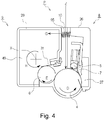
- the cartridge P is constituted to be dismountable from the apparatus main assembly 2 using a cartridge tray 60 that can be pulled out.
- Part (a) of Figure 3 shows a state in which the cartridge tray 60 and the cartridge P are pulled out from the apparatus main assembly 2.
- the recording material S is separated and fed one by one at a predetermined control timing.
- the recording material S is introduced into a secondary transfer portion which is a contact portion between the secondary transfer roller 17 and the transfer belt 12 at a predetermined control timing.
- the first to fourth cartridges P (PY, PM, PC, PK) have the same electrophotographic image forming process mechanism, and the developer color and developer filling amount stored therein can be properly selected.
- Part (a) of Figure 7 shows a state where the drum 4 and the developing roller 6 are in contact with each other. At this time, the force receiving portion 45a and the main assembly separation member 80 are spaced with a gap d.
- the transmission release mechanism 75 in this embodiment is a mechanism generally called a spring clutch.
- the transmission release mechanism 75 comprises members such as an input inner ring (input member, clutch side input member) 75a, an output member (clutch side output member) 75b, a transmission spring (coil spring, elastic member, intermediate transmission member) 75c, a control ring 75d, and a retaining member 75e, for example.
- the upstream transmission member 74 is provided with a drive input portion (coupling portion) 74b at one end in the axial direction, and is a coupling member constituted to receive drive force from the outside of the cartridge (that is, the image forming apparatus main assembly) at the drive input portion 74b.
- a contact end surface 74m is provided on the other end side, in the axial direction, of the upstream transmission member 74, and the contact end surface 74m contacts the input side end surface 75a4 of the transmission release mechanism 75.
- the upstream transmission member 74 is transmitted with a driving force in a state that said it receives an urging force (load U) in the direction of arrow N from the development driving output member 62 of the apparatus main assembly 2. Therefore, the contact end surface 74m of the upstream transmission member 74 is in contact with the input side end surface 75a4 of the transmission release mechanism 75 in a state of being pressed by the urging force U.
- an acting portion 32c of the development cover member 32 is placed, and the acting portion 32c has a first acting portion 32c1 and a second acting portion 32c2.
- the first acting portion 32c1 is a surface facing the first acted portion 76c
- the second acting portion 32c2 is a surface facing the second acted portion 76d.
- the developing unit 9 moves from the contact position, and when the main assembly separating member 80 moves by ⁇ 2 in the direction of arrow F1 and stops, a state is established in which the center of rotation X is rotated by an angle ⁇ 2 in the direction of arrow K. At this time, the drum 4 and the developing roller 6 are separated from each other by a distance ⁇ 2, and the state of the developing unit 9 at this time is the separated position.
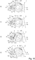
- the control member 76 when the developing unit 9 rotates and reaches the separated position, the control member 76 also rotates, and the contact surface 76b enters inside the rotation locus A of the control ring 75d, as shown in part (c) of Figure 10 .
- the contact surface 76b which has entered the inside of the rotation locus A of the control ring 75d contacts the rotating locked portion 75d4 to stop the rotation of the control ring 75d. By this, transmission of rotational force by the transmission release mechanism 75 is blocked.
- the contact surface 76b is a locking portion which engages with the locked portion 75d4 (locks the locked portion 75d4) and stops the rotation of the locked portion 75d4.
- the rotation of the control member 76 in the direction of the arrow L2 is restricted by the first action portion 32c1, and therefore, depending on the shape design of the first action portion 32c1, it is possible to arbitrarily set the timing at which the contact surface 76b comes out of the rotation locus A and the rotation amount thereof. Therefore, the timing to start transmitting the driving force can be arbitrarily set when the developing unit 9 moves from the separated position to the contact position.
- the arm portion 96b on the other end side of the auxiliary pressing spring 96 is in a non-contact state with respect to the developing unit 9, and it is engaged with a portion 24e of the driving side cartridge cover member 24. That is, it is set so that the urging force Q by the auxiliary pressing spring 96 is not applied to the developing unit 9.
- the arm 96b on the other end side of the auxiliary pressing spring 96 is in contact with the urged portion 32e of the developing unit 9.
- the auxiliary pressing spring 96 imparts a moment, in the direction of arrow H about the rotational center X, to the developing unit 9.
- the developing unit 9 can be reliably shifted from the separated state to the contact state by providing the auxiliary pressing spring 96.
- the contact force between the developing roller 6 and the drum 4 can be prevented from increasing in the state in which the developing unit 9 is in contact with the drum 4, by setting so that the urging force Q by the auxiliary pressing spring 96 does not act on the developing unit 9. By this, the stress imparted to the toner on the developing roller 6 can be reduced.
- the rotational movement of the control member 76 is controlled by the shape of the action portion 32c provided on the development cover member 32 of the developing unit 9, and therefore, the positional relationship between the control member 76 and the transmission release mechanism 75 can be stably maintained relative to the rotation angle of the developing unit 9. More specifically, in the first position of the control member 76, the second operated portion 76d of the control member 76 contacts the second operating portion 32c2, and therefore, the rotational movement of the control member 76 in the direction of the arrow L1 is restricted. Therefore, the contact surface 76b can stably maintain the gap f relative to the rotation locus A.
- the control member 76 applies a rotational moment in the H direction by the force in the direction of the arrow PI from the transmission release mechanism 75.
- the first actuated portion 76c of the control member 76 abuts to the first actuating portion 32c1, so that the rotation of the control member 76 is suppressed. That is, the control member 76 can stably maintain the second position.
- the developing frame (development cover member 32) is provided with an action portion 32c ( Figures 8 and 10 ) for acting on the control member.
- the action portion 32c is a fixed portion fixed to the developing frame.
- the action portion 32c acts on the control member 76 as the developing frame moves (swings and rotates) relative to the support member (the driving side cartridge cover 24, the non-driving side cartridge cover 25, and the cleaning container 26) ( Figure 7 and Figure 10 ).
- the locking portion (contact surface 76b) provided on the control member 76 is rotated between the first position (part (a) in Figure 10 ) and the second position (between part (c) of Figure 10 ).
- the drive transmission through the clutch (transmission release mechanism 75) is switched (turned on and off).
- the second action portion 32c2 of the action portion 32c is brought into contact to the second action portion 76d of the control member 76 to apply a force, so that the contact surface 76b is moved to the first action portion 32c (part (a) in Figure 10 , part (a) in Figure 7 )).
- the transmission of the driving force of the transmission release mechanism 75 is allowed.
- the supporting member that movably supports the developing frame is a photosensitive member supporting frame which rotatably supports the photosensitive member 4 (that is, the driving side cartridge cover 24, the non-driving side cartridge cover 25, and the cleaning container 26). And, the distance between the developing roller 6 and the drum (photosensitive member, photosensitive drum) 4 is changed by the movement of the developing frame relative to the support member ( Figure 7 ).
- the present invention is not limited to such a structure, and a structure in which the support member does not support the drum 4 is also conceivable, for example.
- Embodiment 2 the transmission release mechanism which has been the spring clutch in Embodiment 1 is different. Therefore, the description of the same portions as those in Embodiment 1 is omitted.
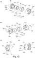
- the transmission release mechanism 170 transmits the rotation of the first transmission member 174 to the second transmission member 171.
- the transmission release mechanism 170 blocks the rotation of the first transmission member 174 and does not transmit the rotation to the second transmission member 171.
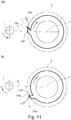
- the drive relay portion 171a slip occurs downstream in the rotational direction J along the driven blocking surface 171a3, between the driven blocking surface 171a3 and the drive blocking surface 175c.
- the driven blocking surface 171a3 rotates relative to the control ring 175 in the rotational direction J by ⁇ t1.
- the drive relay portion 171a is elastically deformed by ⁇ r1 outward in the radial direction.
- the engaged surface 171a1 is retracted from the rotation locus about the rotational axis X of the engagement surface 174e, and as shown in part (b) of Figure 16 , the engagement is released.
- a restoring force (elastic force, elastic restoring force) f3 is produced tending to restore the original position from the state of elastic deformation byx the drive relay portion 171a moving outward in the radial direction.
- the drive relay portion 171a has the supporting portion 171a2 fixed to the inner diameter portion 171h, and therefore, the driven blocking surface 171a3 tends to move inward in the radial direction by the radial component f3r of the restoring force (elastic force) f3.
- the rotation of the control ring 175 is restricted and stopped, and therefore, the drive relay portion 171a receives the reaction force f4 from the drive blocking surface 175c by the driven blocking surface 171a3, so that its position is restricted.
- the movement of the engaged surface 171a1 in the radial direction means that at least a radial component is included in the vector of the moving direction of the engaged surface 171a1, and the vector may contain components other than the radial direction. That is, when the engaged surface 171a1 moves in the radial direction, the engaged surface 171a1 may move in another direction (, for example, the rotational direction) as well at the same time. That is, if the distance from the rotational axis (rotational center) changes as the engaged surface 171a1 moves, it can be regarded as the radial movement.
- the number of engaging surfaces 174e of the first transmission member 174 is three, which is the same as the number of drive relay portions 171a, but, the present invention is not limited to this number.
- the number of the engagement surfaces 174e of the first transmission member 174 is preferably an integer multiple such as 3, 6, 9, and so on, and can be appropriately selected depending on the space.
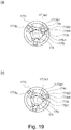
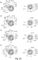
- the transmission release mechanism 270 in this embodiment includes a first transmission member 274, a control ring 275, and a second transmission member 271.
- the transmission release mechanism 270 includes the first transmission member 274, the second transmission member 271, and the control ring 275.
- Figure 25 shows a control ring 2750 which does not have the guide portion 275d as a comparative example of the control ring 275 which has the guide portion 275d.
- Figure 25 is a view of the first transmission member 274, the second transmission member 271, the control ring 2750, and the control member 176 as viewed from the drive side.
- Part (a) of Figure 25 shows the drive transmission state.
- part (b) of Figure 25 shows a state in which the restricting portion 176g of the control member 176 is engaged with the opposing surface 271k2 of the restricting rib 271k.
- the control ring 475d which rotates integrally with the first transmission member 474 starts to rotate relative to the second transmission member 477 which is at rest.
- the drive connection surface 475d6 of the control ring 475d rotates from a state where it is not in contact with the drive relay portion 477d, and the drive connection surface 475d6 starts to contact the introduction surface 477k of the second transmission member 477.
- the introduction surface 477k is a slope connecting the driven connecting surface 477j of the drive relay portion 477d and the arm portion 477g, and the drive connection surface 475d6 advances in the rotational direction J while being in contact with the introduction surface 477k.
- the control portion 475d5 produces a force f42 against the introduction surface 477k at the contact position T42 with the introduction surface 477k.
- the drive relay portion 477d of the second transmission member 477 is a cantilever beam including the supporting portion 477f as a fulcrum.
- the introduction surface 477k which is the free end side of the drive relay portion 477d, receives the force f42 from the drive connection surface 475d6 at the contact position T42, by which a bending moment M42 is generated in the drive relay portion 477d.
- the shape of the engagement surface 174e is selected so that a pulling force f1r inward in the radial direction is produced.
- the shape of the drive transmission surface 474h is set so that the force f41r in the direction of moving outward in the radial direction is produced, in the engagement portion between the drive transmission surface 474h and the engaged surface 477h of the drive relay portion 477d.
- the drive blocking state the deformation of drive relay 477d outward in the radial direction by radial component f41r is allowed, and therefore, the drive relay portion 477d can be deformed outward in the radial direction so that the inscribed circle of the three engaged surfaces 477h is increased. Even if the drive transmission surface 474h of the first transmission member 474 and the engaged surface 477h of the drive relay portion 477d are in contact with each other, engagement therebetween can be avoided.
- the transmission release mechanism blocks the transmission of driving force inside the cartridge.
- the transmission of driving force is blocked in the boundary area (connection area) between the cartridge and the image forming apparatus.
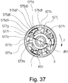
- the output member engagement portion 577p is provided with a drive transmission engagement portion 577e on the circumferential end surface on the downstream side in the rotational direction J, a reverse restricted portion 577n on the circumferential end surface on the upstream side in the rotational direction J, and an axially restricted portion 577q on the end surface side.
- the rotation regulating end surface 577m is a part of the same surface as the reverse restricted portion 577n and is provided on the cylindrical portion 577c side.
- the supporting portion 577f is a connecting portion that is connected to the inner diameter portion 577b as one end side of the drive relay portion 577d, and is a fixed end of the drive relay portion 577d.
- the drive relay portion 577d has an arm portion 577g extending downstream in the rotational direction J from the fixed end (supporting portion 577f).
- the first engaged surface (first driving force receiving portion, engaging portion) 577h is provided radially inward near the free end, and the driven connecting surface 577j is provided radially outward near the free end.
- the drive connecting surface 575d6, the coupling member support surface 575d7, the rotation restricted end surface 575d8, and the second engaged surface 575d9 form a partial annular rib shape.
- a retaining shape portion 575d10 extending inward in the radial direction.
- the transmission release mechanism 575 is supported by the rotational axis X in the developing unit 509 and the cartridge P.
- the transmission release mechanism 575 obtains a driving force from the main assembly driving shaft 562 provided in the apparatus main assembly 2 by way of the coupling member 577 as the first transmission member when mounted in the apparatus main assembly 2.
- the first output member 562a has a retaining flange 562q at the end on the cartridge P side along the rotational axis.
- the diameter of the retaining flange 562q is d50, which is the same as the diameter of the outer peripheral portion 562j. That is, the retaining flange 562q is formed by connecting the outer peripheral portions 562j of partial arc shapes, in the circumferential direction into a circular shape.
- the second output member 562b which transmits drive to the control ring.
- the second output member 562b is coaxial with the first output member 562a and is disposed on the outer side in the radial direction than the first output member 562a.
- the second output member 562b includes an annular rib-shaped second drive transmission portion 562n projecting toward the cartridge P side along the rotational axis.
- a second drive transmission surface 562p is provided on the downstream side in the rotational direction J of the second drive transmission portion 562n.
- the second drive transmission surface 562p transmits the drive to the second engaged surface 575d9 as the second drive force receiving surface (second drive force receiving portion) of the cartridge P.
- the diameter d50 at the outer peripheral portion 562j of the drive transmission portion engaging portion 562g satisfies d50 ⁇ d51 as follows. More specifically, the diameter d51 is 9.6 mm and the diameter d50 is 8 mm.
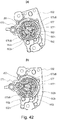
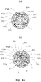
- Part (b) of Figure 43 shows one state in the drive blocking operation in which the control member 576 is in the second position, and the control ring 575d is in one state when moving from the first rotation position to the second rotation position.
- the contact surface 576b of the control member 576 is in a state of being in contact with the locked portion 575d4 of the control ring 575d.
- Part (b) of Figure 41 is a cross-sectional view taken along a plane perpendicular to the rotational axis X at SS3 shown in part (a) of Figure 41 in which the first output member 562a and the second drive transmission portion 562n of the second output member 562b are cut.
- the diameter of the inscribed circle of the three engaged surfaces 577h when the control portion 575d5 contacts the introduction surface 577k is d53.
- the diameter d53 is smaller than the diameter d51 of the inscribed circle R51 in the drive blocking state 1 shown in part (a) of Figure 40 , by the amout by which the drive relay 577d is elastically deformed radially inward.
- the diameter at the time when an inscribed circle R52 is virtually drawn with respect to three engaged surfaces 577h in the drive transmission state is d52.
- the thickness t of the control portion 575d5 is selected such that the diameter d52 resulting from the deformation of the drive relay portion 577d with respect to the diameter d50 at the outer peripheral portion 562j of the drive transmission engagement portion 562g of the main assembly driving shaft 562 satisfies d52 ⁇ d50.
- the contact position in the drive transmission state between the drive transmission surface 562h and the engaged surface 577h of the coupling member 577 is T51.
- the engaged surface 577h receives the reaction force f51 from the drive transmission surface 562h at the contact position T51.
- the drive transmission surface 562h has an inclined surface with an angle ⁇ 51, and the angle ⁇ 51 is an angle toward the upstream side of the rotational direction J as the radius increases with reference to the line connecting the rotational center X and the contact position T51.
- the engaged surface 577h has an arc shape, and therefore, the reaction force f51 at the contact portion between the drive transmission surface 562h and the engaged surface 577h is produced as a normal force of the drive transmission surface 562h.
- the radial direction component f51r and tangential direction component f51t of the reaction force f51 will be described.
- the guide portion 575d11 is a cover portion (cover portion) that covers a portion of them to prevent the control member 576 from stopping the rotations of the coupling member 577, the output member 575b, and the like.
- the guide portion 575d11 is a protection portion which protects the coupling member 577 and the like from the control member 576.
- the control ring 575d stops rotating at the timing when the control member 576 contacts the control ring 575d. And, when the control ring 575d stops rotating, the relative rotation between the coupling member 577 and the control ring 575d is started. As a result, the control portion 575d5 of the control ring 575d retracts from the driven connection surface 577j of the drive relay portion 577d. On the other hand, in the drive blocking operation, the control member 576 continues to rotate in the rotational direction L1 for a certain period of time.
- the first engaged surface 577h receives a driving force from the drive transmission engaging portion 562g, and the coupling member 577 also starts rotating, and the driving force is transmitted toward the developing roller 6.
- the coupling member 577, the control ring 575d, the first output member 562a, and the second output member 562b are all rotating.
- this return spring 575c is provided, and therefore, when the driving force is not transmitted to the cartridge B, the control ring 575d is in the second position, and the engaged surface 577h is also in the second position. Therefore, when mounting the cartridge, it is possible to suppress the engaged surface 577h from interfering with the first output member 562a. That is, the first output member 562a can smoothly enter the coupling member 577.
- control member 576 for controlling the rotation transmission and blocking by the transmission release mechanism 575 ( Figure 42 , and so on) is the same as the control member 76 of Embodiment 1 ( Figures 7 and 10 ).
- the control member 576 of this embodiment can obtain the same effects as those of Embodiment 1 over the prior art. That is, the positional relationship between the control member 576 and the transmission release mechanism 575 can be stably maintained relative to the rotation angle of the developing unit 9, by which it is possible to reliably switch drive transmission and blocking. By this, control variations in the rotation time of the developing roller 6 can be reduced.
- the control portion 575d5 of the control ring 575d moves away (withdraws) from the coupling member 577, and therefore, the first engaged surface 577h is allowed to move away from the axis ( Figure 40 ).
- the first engaged portion 577h can also be retracted to the second position, by eliminating the elastic deformation of the drive relay portion 577d (second receiving portion position: Figure 40 ).
- the first engaged portion 577h does not receive the driving force from the first output member 562a. not only the control ring 575d but also the coupling member 577 stops, and the rotational driving of the developing roller 6 ( Figure 26 ) is also stopped. This is called the drive blocking state 1.
- the transmission release mechanism 575 stops the rotation of the main assembly driving shaft 562 from being inputted to the cartridge and stops the rotation of the downstream transmission member 571.
- the shape of the drive transmission surface 562h is set such that a force f51r in the direction of moving outward in the radial direction is produced in the engagement region between the drive transmission surface 562h and the engaged surface 577h of the drive relay portion 577d.
- the driven connection surface 577j of the drive relay portion 577d receives the radial component f51r in contact with the drive connection surface 575d6 of the control portion 575d5 on the radial extension line from the rotational center X toward the engaged surface 577h.
- the position of the engaged surface 577h of the drive relay portion 577d in the drive transmission state is determined by inserting the thickness t of the control portion 575d5 into the gap between the inner diameter portion 577b and the driven connecting surface 577j in the coupling member 577. For this reason, for example, even when the drive relay portion 577d has changed its natural shape due to creep deformation, and so on, the position of the engaged surface 577h of the drive relay portion 577d in the drive transmission state is stable. Even when repeatedly transmitting and blocking the position of the engaged surface 577h of the drive relay portion 577d in the drive transmission state is also stabilized.
- transmission blocking mechanism it is possible to employ the mechanism (75, 170, 270, 375, 475) for switching between driving transmission and blocking inside the cartridge (parts (a) to (c) of Figures 9 and 16 , Figures 19 and 23 , Figure 29 to Figure 31 and so on). That is, the clutch is provided with the first transmission member and the second transmission member, and transmits and blocks driving force between them.
Landscapes
- Physics & Mathematics (AREA)
- General Physics & Mathematics (AREA)
- Engineering & Computer Science (AREA)
- Computer Vision & Pattern Recognition (AREA)
- Electrophotography Configuration And Component (AREA)
- Dry Development In Electrophotography (AREA)
Applications Claiming Priority (2)
| Application Number | Priority Date | Filing Date | Title |
|---|---|---|---|
| JP2017117890 | 2017-06-15 | ||
| PCT/JP2018/023714 WO2018230744A1 (fr) | 2017-06-15 | 2018-06-15 | Cartouche et dispositif de formation d'image électrophotographique |
Publications (3)
| Publication Number | Publication Date |
|---|---|
| EP3640742A1 true EP3640742A1 (fr) | 2020-04-22 |
| EP3640742A4 EP3640742A4 (fr) | 2021-03-03 |
| EP3640742B1 EP3640742B1 (fr) | 2023-08-16 |
Family
ID=64659134
Family Applications (1)
| Application Number | Title | Priority Date | Filing Date |
|---|---|---|---|
| EP18817519.4A Active EP3640742B1 (fr) | 2017-06-15 | 2018-06-15 | Cartouche et dispositif de formation d'image électrophotographique |
Country Status (18)
| Country | Link |
|---|---|
| US (2) | US11392082B2 (fr) |
| EP (1) | EP3640742B1 (fr) |
| JP (2) | JP7140562B2 (fr) |
| KR (2) | KR102259585B1 (fr) |
| CN (3) | CN115993761B (fr) |
| AU (3) | AU2018283274B2 (fr) |
| BR (1) | BR112019026700A2 (fr) |
| CL (1) | CL2019003580A1 (fr) |
| CO (1) | CO2020000113A2 (fr) |
| MA (1) | MA49405A (fr) |
| MX (1) | MX2019015104A (fr) |
| MY (1) | MY203710A (fr) |
| PH (1) | PH12019502773A1 (fr) |
| RU (1) | RU2749500C1 (fr) |
| SG (2) | SG10202111783UA (fr) |
| TW (2) | TWI720790B (fr) |
| WO (1) | WO2018230744A1 (fr) |
| ZA (1) | ZA201908000B (fr) |
Families Citing this family (17)
| Publication number | Priority date | Publication date | Assignee | Title |
|---|---|---|---|---|
| JP6376749B2 (ja) * | 2013-12-06 | 2018-08-22 | キヤノン株式会社 | プロセスカートリッジおよび電子写真画像形成装置 |
| CN118689065A (zh) | 2019-03-18 | 2024-09-24 | 佳能株式会社 | 电子照相图像形成装置和盒 |
| JP7822723B2 (ja) | 2020-08-31 | 2026-03-03 | キヤノン株式会社 | 感光体ユニット、カートリッジ、電子写真画像形成装置 |
| CN113608420B (zh) * | 2020-09-03 | 2024-12-13 | 中山诚威科技有限公司 | 处理盒 |
| JP7604148B2 (ja) | 2020-09-17 | 2024-12-23 | キヤノン株式会社 | カートリッジ |
| JP2022050270A (ja) | 2020-09-17 | 2022-03-30 | キヤノン株式会社 | 画像形成装置、複数のプロセスカートリッジ、及び連結部材 |
| EP4163730B1 (fr) | 2020-12-07 | 2024-05-22 | Canon Kabushiki Kaisha | Récipient de toner et système de formation d'images |
| WO2022196788A1 (fr) | 2021-03-16 | 2022-09-22 | キヤノン株式会社 | Cartouche de toner et dispositif de formation d'images |
| JP2023049033A (ja) | 2021-09-28 | 2023-04-07 | キヤノン株式会社 | 容器 |
| US12019390B2 (en) * | 2021-11-17 | 2024-06-25 | Sharp Kabushiki Kaisha | Transmission mechanism, rotational force transmission device, and image forming apparatus |
| JP7802510B2 (ja) | 2021-12-07 | 2026-01-20 | キヤノン株式会社 | トナー容器及び画像形成システム |
| JP7793472B2 (ja) * | 2022-04-28 | 2026-01-05 | キヤノン株式会社 | カートリッジ、画像形成装置 |
| US12222674B2 (en) | 2022-06-24 | 2025-02-11 | Canon Kabushiki Kaisha | Cartridge, toner cartridge, and image forming apparatus |
| JP2024002834A (ja) | 2022-06-24 | 2024-01-11 | キヤノン株式会社 | トナーカートリッジ |
| JP7331220B1 (ja) | 2022-08-05 | 2023-08-22 | キヤノン株式会社 | 画像形成装置 |
| CN118483885A (zh) | 2023-02-11 | 2024-08-13 | 江西亿铂电子科技有限公司 | 一种处理盒 |
| JP2024115469A (ja) | 2023-02-14 | 2024-08-26 | キヤノン株式会社 | トナーカートリッジ、画像形成装置及び使用済みトナーカートリッジの再生産方法 |
Family Cites Families (63)
| Publication number | Priority date | Publication date | Assignee | Title |
|---|---|---|---|---|
| GB1158021A (en) | 1966-04-01 | 1969-07-09 | Veeder Root Ltd | Fluid Dispensing Apparatus Control System |
| ES250188Y (es) | 1980-04-22 | 1981-01-01 | Impresora para perfiles de material plastico | |
| JPS6364068A (ja) | 1986-09-05 | 1988-03-22 | Ricoh Co Ltd | 静電記録装置 |
| EP0468752B1 (fr) * | 1990-07-26 | 1995-12-20 | Konica Corporation | Appareil de formation d'images |
| DE69115785T2 (de) * | 1990-07-26 | 1996-11-14 | Konishiroku Photo Ind | Bilderzeugungsgerät |
| JPH0651574A (ja) | 1992-08-03 | 1994-02-25 | Star Micronics Co Ltd | 電子写真装置 |
| JPH06317960A (ja) | 1993-04-28 | 1994-11-15 | Canon Inc | 画像形成装置 |
| JP2688885B2 (ja) | 1994-12-28 | 1997-12-10 | 株式会社三和製作所 | 印字装置 |
| JP3363751B2 (ja) | 1996-08-29 | 2003-01-08 | キヤノン株式会社 | プロセスカートリッジ及び電子写真画像形成装置 |
| JPH10281188A (ja) * | 1997-04-03 | 1998-10-20 | Sankyo Seiki Mfg Co Ltd | 回転伝達装置 |
| JPH10318292A (ja) * | 1997-05-15 | 1998-12-02 | Ricoh Co Ltd | 回転力伝達機構 |
| JP2001337511A (ja) * | 2000-05-26 | 2001-12-07 | Matsushita Electric Ind Co Ltd | カラー画像形成装置 |
| JP3566697B2 (ja) * | 2001-02-09 | 2004-09-15 | キヤノン株式会社 | プロセスカートリッジ、電子写真画像形成装置、及び、離隔機構 |
| US6795671B2 (en) * | 2002-01-15 | 2004-09-21 | Canon Kabushiki Kaisha | Image forming apparatus featuring switchable, contact and spaced, clutch-operated developing units |
| JP4005525B2 (ja) | 2003-03-26 | 2007-11-07 | 京セラミタ株式会社 | 画像形成装置 |
| JP4040636B2 (ja) * | 2005-03-24 | 2008-01-30 | キヤノン株式会社 | プロセスカートリッジ及び電子写真画像形成装置 |
| KR100717037B1 (ko) * | 2005-10-07 | 2007-05-10 | 삼성전자주식회사 | 화상형성장치 |
| JP4241819B2 (ja) | 2006-01-11 | 2009-03-18 | キヤノン株式会社 | カラー電子写真画像形成装置 |
| JP4804212B2 (ja) | 2006-04-19 | 2011-11-02 | キヤノン株式会社 | プロセスカートリッジ及び電子写真画像形成装置及びプロセスカートリッジの生産方法及び再生産方法 |
| CN200965623Y (zh) | 2006-10-16 | 2007-10-24 | 特科技股份有限公司乌龙驹 | 激光打印机感光鼓的驱动结构 |
| JP4040665B1 (ja) | 2006-12-28 | 2008-01-30 | キヤノン株式会社 | カラー電子写真画像形成装置 |
| JP5004833B2 (ja) | 2007-05-23 | 2012-08-22 | キヤノン株式会社 | 電子写真画像形成装置 |
| JP4458377B2 (ja) | 2007-06-29 | 2010-04-28 | キヤノン株式会社 | プロセスカートリッジ及び電子写真画像形成装置 |
| JP2009092812A (ja) | 2007-10-05 | 2009-04-30 | Ricoh Co Ltd | 画像形成装置 |
| JP4743199B2 (ja) | 2007-12-28 | 2011-08-10 | ブラザー工業株式会社 | 画像形成装置およびプロセスカートリッジ |
| JP5067156B2 (ja) | 2007-12-28 | 2012-11-07 | ブラザー工業株式会社 | 画像形成装置 |
| JP2009265628A (ja) | 2008-04-01 | 2009-11-12 | Canon Inc | 画像形成装置 |
| JP5328230B2 (ja) | 2008-06-10 | 2013-10-30 | キヤノン株式会社 | カートリッジ、及び、前記カートリッジを用いた電子写真画像形成装置 |
| JP5127584B2 (ja) * | 2008-06-20 | 2013-01-23 | キヤノン株式会社 | ドラムユニット、及び、電子写真画像形成装置 |
| JP5419584B2 (ja) | 2008-09-01 | 2014-02-19 | キヤノン株式会社 | カートリッジ及び電子写真画像形成装置 |
| JP5751779B2 (ja) | 2009-10-30 | 2015-07-22 | キヤノン株式会社 | 現像装置、現像カートリッジ、プロセスカートリッジ、及び、画像形成装置 |
| JP5172877B2 (ja) | 2009-12-24 | 2013-03-27 | 京セラドキュメントソリューションズ株式会社 | クラッチ機構並びにクラッチ機構を備える処理装置及び画像形成装置 |
| JP4846062B1 (ja) | 2010-08-20 | 2011-12-28 | キヤノン株式会社 | カートリッジ及び画像形成装置 |
| KR101615652B1 (ko) | 2011-01-06 | 2016-04-26 | 삼성전자 주식회사 | 프로세스 카트리지 및 이를 가지는 화상형성장치 |
| EP2776892B1 (fr) | 2011-11-09 | 2019-06-05 | Canon Kabushiki Kaisha | Cartuche avec une électrode |
| JP5460824B2 (ja) | 2011-12-09 | 2014-04-02 | キヤノン株式会社 | カートリッジ |
| JP6128823B2 (ja) | 2011-12-21 | 2017-05-17 | キヤノン株式会社 | 現像容器、その製造方法、それを用いる現像装置及び画像形成装置 |
| WO2013099999A2 (fr) | 2011-12-26 | 2013-07-04 | Canon Kabushiki Kaisha | Dispositif de développement, cartouche de traitement et unité à tambour |
| JP6004690B2 (ja) | 2012-03-21 | 2016-10-12 | キヤノン株式会社 | プロセスカートリッジ及び画像形成装置 |
| JP5675888B2 (ja) | 2012-05-17 | 2015-02-25 | キヤノン株式会社 | 現像剤収納ユニット、現像装置、プロセスカートリッジ、画像形成装置 |
| JP6112783B2 (ja) | 2012-06-08 | 2017-04-12 | キヤノン株式会社 | 梱包体 |
| KR101919185B1 (ko) | 2012-06-08 | 2018-11-15 | 캐논 가부시끼가이샤 | 포장 부재 및 포장 부재에 포장된 카트리지 |
| CN110426937B (zh) | 2012-06-15 | 2022-08-19 | 佳能株式会社 | 处理盒 |
| JP2014032247A (ja) * | 2012-08-01 | 2014-02-20 | Ricoh Co Ltd | 転写装置及び画像形成装置 |
| JP6108728B2 (ja) | 2012-08-31 | 2017-04-05 | キヤノン株式会社 | 梱包材及びカートリッジ |
| JP6218493B2 (ja) | 2012-09-06 | 2017-10-25 | キヤノン株式会社 | ユニット、ユニットの製造方法、及び画像形成装置、画像形成装置の製造方法 |
| JP6202911B2 (ja) | 2012-09-07 | 2017-09-27 | キヤノン株式会社 | 画像形成装置、プロセスカートリッジ |
| US9387702B2 (en) | 2012-12-28 | 2016-07-12 | Shenzhen Pu Ying Innovation Technology Corporation Limited | Printer with improved paper board |
| JP5631443B2 (ja) * | 2013-05-27 | 2014-11-26 | キヤノン株式会社 | プロセスカートリッジ |
| US9104141B2 (en) * | 2013-05-29 | 2015-08-11 | Lexmark International, Inc. | Toner cartridge having a shutter with bypassing actuation |
| JP2014237472A (ja) | 2013-06-07 | 2014-12-18 | キヤノン株式会社 | 梱包部材、梱包部材に梱包されたカートリッジ |
| JP6338460B2 (ja) | 2013-08-20 | 2018-06-06 | キヤノン株式会社 | カートリッジ及び画像形成装置 |
| JP6376749B2 (ja) * | 2013-12-06 | 2018-08-22 | キヤノン株式会社 | プロセスカートリッジおよび電子写真画像形成装置 |
| JP6223160B2 (ja) | 2013-12-10 | 2017-11-01 | キヤノン株式会社 | 撮像装置、その制御方法、および制御プログラム |
| JP5791691B2 (ja) | 2013-12-11 | 2015-10-07 | キヤノン株式会社 | 駆動伝達機構及びそれを備えた画像形成装置 |
| JP6552212B2 (ja) | 2015-02-16 | 2019-07-31 | キヤノン株式会社 | カートリッジ及び画像形成装置並びにカートリッジの製造方法 |
| JP6598468B2 (ja) | 2015-02-16 | 2019-10-30 | キヤノン株式会社 | カートリッジ及び画像形成装置並びにカートリッジの製造方法 |
| JP6562655B2 (ja) | 2015-02-27 | 2019-08-21 | キヤノン株式会社 | カートリッジおよび画像形成装置 |
| CN104712319A (zh) * | 2015-03-13 | 2015-06-17 | 成都大漠石油机械有限公司 | 油井倾斜度测量装置 |
| US9964911B2 (en) * | 2015-03-20 | 2018-05-08 | Canon Kabushiki Kaisha | Driving force transmitting apparatus and image forming apparatus |
| JP6873604B2 (ja) | 2015-06-05 | 2021-05-19 | キヤノン株式会社 | プロセスカートリッジ、および、電子写真画像形成装置 |
| JP6983518B2 (ja) | 2016-03-04 | 2021-12-17 | キヤノン株式会社 | プロセスカートリッジ |
| JP7080678B2 (ja) | 2018-03-13 | 2022-06-06 | キヤノン株式会社 | カートリッジ |
-
2018
- 2018-06-15 MA MA049405A patent/MA49405A/fr unknown
- 2018-06-15 EP EP18817519.4A patent/EP3640742B1/fr active Active
- 2018-06-15 CN CN202211656685.6A patent/CN115993761B/zh active Active
- 2018-06-15 TW TW109101960A patent/TWI720790B/zh active
- 2018-06-15 TW TW107120681A patent/TWI723270B/zh active
- 2018-06-15 SG SG10202111783UA patent/SG10202111783UA/en unknown
- 2018-06-15 MY MYPI2019007476A patent/MY203710A/en unknown
- 2018-06-15 AU AU2018283274A patent/AU2018283274B2/en active Active
- 2018-06-15 CN CN201880048831.2A patent/CN110945440B/zh active Active
- 2018-06-15 KR KR1020217005813A patent/KR102259585B1/ko active Active
- 2018-06-15 PH PH1/2019/502773A patent/PH12019502773A1/en unknown
- 2018-06-15 BR BR112019026700-0A patent/BR112019026700A2/pt unknown
- 2018-06-15 SG SG11201912160PA patent/SG11201912160PA/en unknown
- 2018-06-15 WO PCT/JP2018/023714 patent/WO2018230744A1/fr not_active Ceased
- 2018-06-15 MX MX2019015104A patent/MX2019015104A/es unknown
- 2018-06-15 CN CN202211656044.0A patent/CN115877688A/zh active Pending
- 2018-06-15 RU RU2020100863A patent/RU2749500C1/ru active
- 2018-06-15 JP JP2018114707A patent/JP7140562B2/ja active Active
- 2018-06-15 KR KR1020207001377A patent/KR102223456B1/ko active Active
-
2019
- 2019-12-02 ZA ZA2019/08000A patent/ZA201908000B/en unknown
- 2019-12-06 CL CL2019003580A patent/CL2019003580A1/es unknown
- 2019-12-13 US US16/713,561 patent/US11392082B2/en active Active
-
2020
- 2020-01-07 CO CONC2020/0000113A patent/CO2020000113A2/es unknown
-
2021
- 2021-03-30 AU AU2021201973A patent/AU2021201973A1/en not_active Abandoned
- 2021-10-25 US US17/509,184 patent/US12072669B2/en active Active
-
2022
- 2022-08-26 JP JP2022134561A patent/JP7487269B2/ja active Active
-
2023
- 2023-03-27 AU AU2023201865A patent/AU2023201865B2/en active Active
Also Published As
Similar Documents
| Publication | Publication Date | Title |
|---|---|---|
| EP3640742B1 (fr) | Cartouche et dispositif de formation d'image électrophotographique | |
| JP5288769B2 (ja) | 画像形成装置 | |
| US9037036B2 (en) | Opening and closing mechanism and image-forming apparatus | |
| US10747144B2 (en) | Toner cartridge and toner supplying mechanism | |
| EP3462247B1 (fr) | Appareil de formation d'images | |
| JP5355131B2 (ja) | カートリッジ及び電子写真画像形成装置 | |
| CA3067526C (fr) | Cartouche et dispositif de formation d'image electrophotographique | |
| HK40016466A (en) | Cartridge and electrophotographic image formation device | |
| HK40082984A (en) | Cartridge and electrophotographic image formation device | |
| HK40016466B (en) | Cartridge and electrophotographic image formation device | |
| HK40084192A (en) | Cartridge and electrophotographic image formation device | |
| JP7019434B2 (ja) | トナー搬送装置及び像担持体ユニット | |
| JP4804182B2 (ja) | 電子写真画像形成装置 |
Legal Events
| Date | Code | Title | Description |
|---|---|---|---|
| STAA | Information on the status of an ep patent application or granted ep patent |
Free format text: STATUS: THE INTERNATIONAL PUBLICATION HAS BEEN MADE |
|
| PUAI | Public reference made under article 153(3) epc to a published international application that has entered the european phase |
Free format text: ORIGINAL CODE: 0009012 |
|
| STAA | Information on the status of an ep patent application or granted ep patent |
Free format text: STATUS: REQUEST FOR EXAMINATION WAS MADE |
|
| 17P | Request for examination filed |
Effective date: 20200115 |
|
| AK | Designated contracting states |
Kind code of ref document: A1 Designated state(s): AL AT BE BG CH CY CZ DE DK EE ES FI FR GB GR HR HU IE IS IT LI LT LU LV MC MK MT NL NO PL PT RO RS SE SI SK SM TR |
|
| AX | Request for extension of the european patent |
Extension state: BA ME |
|
| A4 | Supplementary search report drawn up and despatched |
Effective date: 20210129 |
|
| RIC1 | Information provided on ipc code assigned before grant |
Ipc: G03G 15/08 20060101ALI20210125BHEP Ipc: G03G 21/18 20060101AFI20210125BHEP |
|
| GRAP | Despatch of communication of intention to grant a patent |
Free format text: ORIGINAL CODE: EPIDOSNIGR1 |
|
| STAA | Information on the status of an ep patent application or granted ep patent |
Free format text: STATUS: GRANT OF PATENT IS INTENDED |
|
| INTG | Intention to grant announced |
Effective date: 20230302 |
|
| GRAS | Grant fee paid |
Free format text: ORIGINAL CODE: EPIDOSNIGR3 |
|
| GRAA | (expected) grant |
Free format text: ORIGINAL CODE: 0009210 |
|
| STAA | Information on the status of an ep patent application or granted ep patent |
Free format text: STATUS: THE PATENT HAS BEEN GRANTED |
|
| AK | Designated contracting states |
Kind code of ref document: B1 Designated state(s): AL AT BE BG CH CY CZ DE DK EE ES FI FR GB GR HR HU IE IS IT LI LT LU LV MC MK MT NL NO PL PT RO RS SE SI SK SM TR |
|
| REG | Reference to a national code |
Ref country code: CH Ref legal event code: EP |
|
| REG | Reference to a national code |
Ref country code: DE Ref legal event code: R096 Ref document number: 602018055581 Country of ref document: DE |
|
| REG | Reference to a national code |
Ref country code: IE Ref legal event code: FG4D |
|
| REG | Reference to a national code |
Ref country code: LT Ref legal event code: MG9D |
|
| REG | Reference to a national code |
Ref country code: NL Ref legal event code: MP Effective date: 20230816 |
|
| REG | Reference to a national code |
Ref country code: AT Ref legal event code: MK05 Ref document number: 1600654 Country of ref document: AT Kind code of ref document: T Effective date: 20230816 |
|
| PG25 | Lapsed in a contracting state [announced via postgrant information from national office to epo] |
Ref country code: GR Free format text: LAPSE BECAUSE OF FAILURE TO SUBMIT A TRANSLATION OF THE DESCRIPTION OR TO PAY THE FEE WITHIN THE PRESCRIBED TIME-LIMIT Effective date: 20231117 |
|
| PG25 | Lapsed in a contracting state [announced via postgrant information from national office to epo] |
Ref country code: IS Free format text: LAPSE BECAUSE OF FAILURE TO SUBMIT A TRANSLATION OF THE DESCRIPTION OR TO PAY THE FEE WITHIN THE PRESCRIBED TIME-LIMIT Effective date: 20231216 |
|
| PG25 | Lapsed in a contracting state [announced via postgrant information from national office to epo] |
Ref country code: SE Free format text: LAPSE BECAUSE OF FAILURE TO SUBMIT A TRANSLATION OF THE DESCRIPTION OR TO PAY THE FEE WITHIN THE PRESCRIBED TIME-LIMIT Effective date: 20230816 Ref country code: RS Free format text: LAPSE BECAUSE OF FAILURE TO SUBMIT A TRANSLATION OF THE DESCRIPTION OR TO PAY THE FEE WITHIN THE PRESCRIBED TIME-LIMIT Effective date: 20230816 Ref country code: PT Free format text: LAPSE BECAUSE OF FAILURE TO SUBMIT A TRANSLATION OF THE DESCRIPTION OR TO PAY THE FEE WITHIN THE PRESCRIBED TIME-LIMIT Effective date: 20231218 Ref country code: NO Free format text: LAPSE BECAUSE OF FAILURE TO SUBMIT A TRANSLATION OF THE DESCRIPTION OR TO PAY THE FEE WITHIN THE PRESCRIBED TIME-LIMIT Effective date: 20231116 Ref country code: NL Free format text: LAPSE BECAUSE OF FAILURE TO SUBMIT A TRANSLATION OF THE DESCRIPTION OR TO PAY THE FEE WITHIN THE PRESCRIBED TIME-LIMIT Effective date: 20230816 Ref country code: LV Free format text: LAPSE BECAUSE OF FAILURE TO SUBMIT A TRANSLATION OF THE DESCRIPTION OR TO PAY THE FEE WITHIN THE PRESCRIBED TIME-LIMIT Effective date: 20230816 Ref country code: LT Free format text: LAPSE BECAUSE OF FAILURE TO SUBMIT A TRANSLATION OF THE DESCRIPTION OR TO PAY THE FEE WITHIN THE PRESCRIBED TIME-LIMIT Effective date: 20230816 Ref country code: IS Free format text: LAPSE BECAUSE OF FAILURE TO SUBMIT A TRANSLATION OF THE DESCRIPTION OR TO PAY THE FEE WITHIN THE PRESCRIBED TIME-LIMIT Effective date: 20231216 Ref country code: HR Free format text: LAPSE BECAUSE OF FAILURE TO SUBMIT A TRANSLATION OF THE DESCRIPTION OR TO PAY THE FEE WITHIN THE PRESCRIBED TIME-LIMIT Effective date: 20230816 Ref country code: GR Free format text: LAPSE BECAUSE OF FAILURE TO SUBMIT A TRANSLATION OF THE DESCRIPTION OR TO PAY THE FEE WITHIN THE PRESCRIBED TIME-LIMIT Effective date: 20231117 Ref country code: FI Free format text: LAPSE BECAUSE OF FAILURE TO SUBMIT A TRANSLATION OF THE DESCRIPTION OR TO PAY THE FEE WITHIN THE PRESCRIBED TIME-LIMIT Effective date: 20230816 Ref country code: AT Free format text: LAPSE BECAUSE OF FAILURE TO SUBMIT A TRANSLATION OF THE DESCRIPTION OR TO PAY THE FEE WITHIN THE PRESCRIBED TIME-LIMIT Effective date: 20230816 |
|
| PG25 | Lapsed in a contracting state [announced via postgrant information from national office to epo] |
Ref country code: PL Free format text: LAPSE BECAUSE OF FAILURE TO SUBMIT A TRANSLATION OF THE DESCRIPTION OR TO PAY THE FEE WITHIN THE PRESCRIBED TIME-LIMIT Effective date: 20230816 |
|
| PG25 | Lapsed in a contracting state [announced via postgrant information from national office to epo] |
Ref country code: ES Free format text: LAPSE BECAUSE OF FAILURE TO SUBMIT A TRANSLATION OF THE DESCRIPTION OR TO PAY THE FEE WITHIN THE PRESCRIBED TIME-LIMIT Effective date: 20230816 |
|
| PG25 | Lapsed in a contracting state [announced via postgrant information from national office to epo] |
Ref country code: SM Free format text: LAPSE BECAUSE OF FAILURE TO SUBMIT A TRANSLATION OF THE DESCRIPTION OR TO PAY THE FEE WITHIN THE PRESCRIBED TIME-LIMIT Effective date: 20230816 Ref country code: RO Free format text: LAPSE BECAUSE OF FAILURE TO SUBMIT A TRANSLATION OF THE DESCRIPTION OR TO PAY THE FEE WITHIN THE PRESCRIBED TIME-LIMIT Effective date: 20230816 Ref country code: ES Free format text: LAPSE BECAUSE OF FAILURE TO SUBMIT A TRANSLATION OF THE DESCRIPTION OR TO PAY THE FEE WITHIN THE PRESCRIBED TIME-LIMIT Effective date: 20230816 Ref country code: EE Free format text: LAPSE BECAUSE OF FAILURE TO SUBMIT A TRANSLATION OF THE DESCRIPTION OR TO PAY THE FEE WITHIN THE PRESCRIBED TIME-LIMIT Effective date: 20230816 Ref country code: DK Free format text: LAPSE BECAUSE OF FAILURE TO SUBMIT A TRANSLATION OF THE DESCRIPTION OR TO PAY THE FEE WITHIN THE PRESCRIBED TIME-LIMIT Effective date: 20230816 Ref country code: CZ Free format text: LAPSE BECAUSE OF FAILURE TO SUBMIT A TRANSLATION OF THE DESCRIPTION OR TO PAY THE FEE WITHIN THE PRESCRIBED TIME-LIMIT Effective date: 20230816 Ref country code: SK Free format text: LAPSE BECAUSE OF FAILURE TO SUBMIT A TRANSLATION OF THE DESCRIPTION OR TO PAY THE FEE WITHIN THE PRESCRIBED TIME-LIMIT Effective date: 20230816 |
|
| VS25 | Lapsed in a validation state [announced via postgrant information from nat. office to epo] |
Ref country code: MD Free format text: LAPSE BECAUSE OF FAILURE TO SUBMIT A TRANSLATION OF THE DESCRIPTION OR TO PAY THE FEE WITHIN THE PRESCRIBED TIME-LIMIT Effective date: 20230816 |
|
| REG | Reference to a national code |
Ref country code: DE Ref legal event code: R097 Ref document number: 602018055581 Country of ref document: DE |
|
| PLBE | No opposition filed within time limit |
Free format text: ORIGINAL CODE: 0009261 |
|
| STAA | Information on the status of an ep patent application or granted ep patent |
Free format text: STATUS: NO OPPOSITION FILED WITHIN TIME LIMIT |
|
| 26N | No opposition filed |
Effective date: 20240517 |
|
| PG25 | Lapsed in a contracting state [announced via postgrant information from national office to epo] |
Ref country code: IT Free format text: LAPSE BECAUSE OF FAILURE TO SUBMIT A TRANSLATION OF THE DESCRIPTION OR TO PAY THE FEE WITHIN THE PRESCRIBED TIME-LIMIT Effective date: 20230816 Ref country code: SI Free format text: LAPSE BECAUSE OF FAILURE TO SUBMIT A TRANSLATION OF THE DESCRIPTION OR TO PAY THE FEE WITHIN THE PRESCRIBED TIME-LIMIT Effective date: 20230816 |
|
| PG25 | Lapsed in a contracting state [announced via postgrant information from national office to epo] |
Ref country code: BG Free format text: LAPSE BECAUSE OF FAILURE TO SUBMIT A TRANSLATION OF THE DESCRIPTION OR TO PAY THE FEE WITHIN THE PRESCRIBED TIME-LIMIT Effective date: 20230816 |
|
| PG25 | Lapsed in a contracting state [announced via postgrant information from national office to epo] |
Ref country code: BG Free format text: LAPSE BECAUSE OF FAILURE TO SUBMIT A TRANSLATION OF THE DESCRIPTION OR TO PAY THE FEE WITHIN THE PRESCRIBED TIME-LIMIT Effective date: 20230816 |
|
| PG25 | Lapsed in a contracting state [announced via postgrant information from national office to epo] |
Ref country code: MC Free format text: LAPSE BECAUSE OF FAILURE TO SUBMIT A TRANSLATION OF THE DESCRIPTION OR TO PAY THE FEE WITHIN THE PRESCRIBED TIME-LIMIT Effective date: 20230816 |
|
| REG | Reference to a national code |
Ref country code: CH Ref legal event code: PL |
|
| PG25 | Lapsed in a contracting state [announced via postgrant information from national office to epo] |
Ref country code: LU Free format text: LAPSE BECAUSE OF NON-PAYMENT OF DUE FEES Effective date: 20240615 |
|
| PG25 | Lapsed in a contracting state [announced via postgrant information from national office to epo] |
Ref country code: IE Free format text: LAPSE BECAUSE OF NON-PAYMENT OF DUE FEES Effective date: 20240615 |
|
| PG25 | Lapsed in a contracting state [announced via postgrant information from national office to epo] |
Ref country code: CH Free format text: LAPSE BECAUSE OF NON-PAYMENT OF DUE FEES Effective date: 20240630 Ref country code: BE Free format text: LAPSE BECAUSE OF NON-PAYMENT OF DUE FEES Effective date: 20240630 |
|
| REG | Reference to a national code |
Ref country code: BE Ref legal event code: MM Effective date: 20240630 |
|
| PGFP | Annual fee paid to national office [announced via postgrant information from national office to epo] |
Ref country code: DE Payment date: 20250520 Year of fee payment: 8 |
|
| PGFP | Annual fee paid to national office [announced via postgrant information from national office to epo] |
Ref country code: GB Payment date: 20250520 Year of fee payment: 8 |
|
| PGFP | Annual fee paid to national office [announced via postgrant information from national office to epo] |
Ref country code: FR Payment date: 20250520 Year of fee payment: 8 |
|
| VS25 | Lapsed in a validation state [announced via postgrant information from nat. office to epo] |
Ref country code: MA Free format text: FAILURE TO ELECT DOMICILE IN THE NATIONAL COUNTRY Effective date: 20231117 |
|
| PG25 | Lapsed in a contracting state [announced via postgrant information from national office to epo] |
Ref country code: CY Free format text: LAPSE BECAUSE OF FAILURE TO SUBMIT A TRANSLATION OF THE DESCRIPTION OR TO PAY THE FEE WITHIN THE PRESCRIBED TIME-LIMIT; INVALID AB INITIO Effective date: 20180615 |
|
| PG25 | Lapsed in a contracting state [announced via postgrant information from national office to epo] |
Ref country code: HU Free format text: LAPSE BECAUSE OF FAILURE TO SUBMIT A TRANSLATION OF THE DESCRIPTION OR TO PAY THE FEE WITHIN THE PRESCRIBED TIME-LIMIT; INVALID AB INITIO Effective date: 20180615 |