EP3641076A1 - Logement de bague collectrice comportant une serrure à baïonnette - Google Patents
Logement de bague collectrice comportant une serrure à baïonnette Download PDFInfo
- Publication number
- EP3641076A1 EP3641076A1 EP19180216.4A EP19180216A EP3641076A1 EP 3641076 A1 EP3641076 A1 EP 3641076A1 EP 19180216 A EP19180216 A EP 19180216A EP 3641076 A1 EP3641076 A1 EP 3641076A1
- Authority
- EP
- European Patent Office
- Prior art keywords
- slipring
- housing
- locking ring
- bayonet lock
- bearing
- Prior art date
- Legal status (The legal status is an assumption and is not a legal conclusion. Google has not performed a legal analysis and makes no representation as to the accuracy of the status listed.)
- Granted
Links
Images


Classifications
-
- H—ELECTRICITY
- H01—ELECTRIC ELEMENTS
- H01R—ELECTRICALLY-CONDUCTIVE CONNECTIONS; STRUCTURAL ASSOCIATIONS OF A PLURALITY OF MUTUALLY-INSULATED ELECTRICAL CONNECTING ELEMENTS; COUPLING DEVICES; CURRENT COLLECTORS
- H01R13/00—Details of coupling devices of the kinds covered by groups H01R12/70 or H01R24/00 - H01R33/00
- H01R13/62—Means for facilitating engagement or disengagement of coupling parts or for holding them in engagement
- H01R13/625—Casing or ring with bayonet engagement
-
- H—ELECTRICITY
- H01—ELECTRIC ELEMENTS
- H01R—ELECTRICALLY-CONDUCTIVE CONNECTIONS; STRUCTURAL ASSOCIATIONS OF A PLURALITY OF MUTUALLY-INSULATED ELECTRICAL CONNECTING ELEMENTS; COUPLING DEVICES; CURRENT COLLECTORS
- H01R39/00—Rotary current collectors, distributors or interrupters
- H01R39/02—Details for dynamo electric machines
- H01R39/08—Slip-rings
- H01R39/10—Slip-rings other than with external cylindrical contact surface, e.g. flat slip-rings
-
- H—ELECTRICITY
- H01—ELECTRIC ELEMENTS
- H01R—ELECTRICALLY-CONDUCTIVE CONNECTIONS; STRUCTURAL ASSOCIATIONS OF A PLURALITY OF MUTUALLY-INSULATED ELECTRICAL CONNECTING ELEMENTS; COUPLING DEVICES; CURRENT COLLECTORS
- H01R39/00—Rotary current collectors, distributors or interrupters
- H01R39/64—Devices for uninterrupted current collection
- H01R39/643—Devices for uninterrupted current collection through ball or roller bearing
-
- H—ELECTRICITY
- H01—ELECTRIC ELEMENTS
- H01R—ELECTRICALLY-CONDUCTIVE CONNECTIONS; STRUCTURAL ASSOCIATIONS OF A PLURALITY OF MUTUALLY-INSULATED ELECTRICAL CONNECTING ELEMENTS; COUPLING DEVICES; CURRENT COLLECTORS
- H01R13/00—Details of coupling devices of the kinds covered by groups H01R12/70 or H01R24/00 - H01R33/00
- H01R13/66—Structural association with built-in electrical component
- H01R13/665—Structural association with built-in electrical component with built-in electronic circuit
- H01R13/6658—Structural association with built-in electrical component with built-in electronic circuit on printed circuit board
-
- H—ELECTRICITY
- H01—ELECTRIC ELEMENTS
- H01R—ELECTRICALLY-CONDUCTIVE CONNECTIONS; STRUCTURAL ASSOCIATIONS OF A PLURALITY OF MUTUALLY-INSULATED ELECTRICAL CONNECTING ELEMENTS; COUPLING DEVICES; CURRENT COLLECTORS
- H01R39/00—Rotary current collectors, distributors or interrupters
- H01R39/02—Details for dynamo electric machines
- H01R39/14—Fastenings of commutators or slip-rings to shafts
Definitions
- the invention relates to slipring devices for transmission of electrical signals between rotating parts. Specifically, it relates to housings of such slipring devices.
- sliprings are used to transfer electrical power and/or signals between a rotating and a stationary part. Such sliprings are used in different applications, like wind energy plants or computer tomography scanners. There are also many industrial, military, and aerospace applications in which sliprings are used.
- the sliprings should have a housing which allows simple integration into complex machines.
- the housing further should provide a sufficient protection against dust, debris, and liquids.
- the housing should allow easy disassembly of the slipring device for maintenance purposes.
- EP 2 696 443 B1 A very robust and complex multifunctional slipring housing is disclosed in EP 2 696 443 B1 . It has a very high degree of sealing, but requires a large number of screws to be removed for opening the housing.
- EP 1 026 794 B1 discloses a slipring in a plate-like arrangement. Due to the complex interior assembly and the multiply screwed housing, the disassembly is only possible with extremely high efforts.
- US 4,485,278 discloses a device for automatically winding up a feeder cable.
- a spring housing is attached by a bayonet lock to a drum.
- the housing parts are held by a snap lock connection (locking pawls 1.2).
- There is also no hollow shaft comprising at least one bayonet lock notch and no locking ring having at least one bayonet lock protrusion oriented in a radial direction to the center axis.
- EP 3 096 175 A2 discloses binoculars having a sliding contact connection. There is also no hollow shaft comprising at least one bayonet lock notch and no locking ring having at least one bayonet lock protrusion oriented in a radial direction to the center axis. Instead of the locking ring, there is a pin 6 ( Figure 15) which protrudes into the tubular protrusion and interfaces with the first part (5).
- US 2008/0192975 A1 discloses a sliding contact device having a printed circuit board.
- EP 3 316 425 A1 discloses a 3D-printed slipring module.
- CH 246 799 discloses a stacked slipring arrangement.
- the problem to be solved by the invention is to provide a slipring device and a slipring housing which can easily be integrated in a complex environment and which further can easily be assembled in manufacturing and which can easily be disassembled for maintenance.
- a slipring device comprises a first part and a second part which are rotatable against each other about a center axis.
- the first part may be stationary, whereas the second part may be rotating relative thereto.
- the rotating and stationary parts may be exchanged or even both parts may be rotating with different speeds.
- the first part comprises a first housing which may contain all necessary slipring components.
- a component may be at least one sliding track and/or one sliding brush.
- the slipring component comprises a printed circuit board which may have a sliding track as a PCB trace, and/or a brush mounted and/or soldered to the PCB.
- the second part arranged opposite to the first part also has a second housing and may further comprise slipring parts, like at least one a sliding track and/or one sliding brush.
- the slipring component comprises a printed circuit board which may have a sliding track as a PCB trace, and/or a brush mounted and/or soldered to the PCB.
- the slipring components in the first part and the second part are designed such that they interface in a way to form a sliding contact connection. Therefore, a contact brush at the first part interfaces with the sliding track at the second part and/or a contact brush at the second part interfaces with a sliding track at the first part. Preferably, multiple sliding contact connections are provided between the first part and the second part.
- the first housing includes a hollow shaft which serves as a guidance for the second part and holds a locking means which preferably is a locking ring.
- the hollow shaft preferably has a free inner bore over its total length. This may allow to feed cables, waveguides and pipes through the hollow shaft and may even allow to insert further rotary joints.
- the locking ring holds and locks the first part against the second part.
- the spring may be a spring between the locking ring and the first and/or second part to ensure a certain and preferably a constant pressure between the first and the second part to hold these parts in place.
- the spring is a wave spring or plate spring or a disk spring.
- the spring is formed as one part with the locking ring.
- the locking ring is a 3D printed part which has an integrated spring or multiple springs. This is a significant advantage over standard manufacturing methods, as these do not allow to combine the spring with the locking ring.
- any part of the device may be made by a 3-D printing process. High-volume manufacturing may be performed by injection-molding.
- the locking ring has a bayonet lock which allows simple assembly and disassembly of the slipring device.
- the locking ring may also have a thread or any other means for holding it in position.
- the hollow shaft has at least one notch or a plurality of notches
- the locking ring has at least one protrusion for interfacing with the notches of the hollow shaft.
- the protrusion is oriented in a radial direction to the center axis. The order of the notches and protrusions may be exchanged.
- Assembly of the slipring device is very simple.
- the second part only has to be placed on the hollow shaft of the first part.
- the locking ring has to be placed on the hollow shaft and to be locked. Locking is preferably done by locking the bayonet lock by pressing the locking ring down in a locking position and then rotating the locking ring until the bayonet lock locks.
- To unlock and disassemble the housing e.g. for service the locking ring may be rotated in the opposite direction. The direction may be counter clockwise for disassembly and clockwise for assembly.
- the housing parts when manufactured from plastic material e.g. in a 3D printing process or injection molding process might incorporate metal threaded inserts to allow stable mounting of the slipring to a customer interface or to mount a torque bridge. Also, a metal or absorbent coating might be applied to the inner housing surface for shielding of the slipring to reduce electromagnetic emissions or improve electromagnetic susceptibility of the slipring.
- the housing may comprise a metal, e.g. aluminum.
- the first housing and/or the second housing are made of metal.
- the first bearing is arranged between the first housing and the second housing in a direction parallel to the center axis.
- the hollow shaft holds the second part and/or the second housing.
- a simple position encoder can also be integrated by 3-D-printing a resistive substrate formed as a circle with the center at the rotation axis onto the inner surface of one part of the housing.
- the substrate is contacted by at least one electrode static to the printed substrate and a metal brush that is mounted to the other part of the housing and that moves angularly with the rotation of the slipring so that an absolute or relative resistor value measured between the sliding brush and the at least one static electrode represents an angular position between the two housings to serve as an encoder.
- the housing might also only partially cover the slipring to reduce costs or mass or inertia of the slipring.
- Connectors might be mounted to the housing or to at least one of the printed circuit boards.
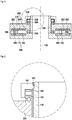
- the slipring device basically comprises a first part 100 and a second part 200, which are rotatable against each other about a center axis 130.
- the first part 100 has a first housing 110 which holds a first printed circuit board (PCB) 180.
- This PCB may hold at least one first sliding track 182 and/or at least one contact brush 190.
- the second part 200 has a second housing 210 with a second PCB 280.
- the second PCB 280 has at least one second contact brush 290 and at least one second sliding track 282.
- the sliding tracks and brushes are arranged such that a sliding track of the first PCB interfaces with a sliding brush of the second PCB, and vice versa to accomplish an electrical contact.
- Between the first housing 110 and the second housing 210 is at least a first bearing 310 which provides mechanical support and allows rotation of the second housing against the first housing. It is preferred to have at least a second bearing 320.
- the first housing 110 has a hollow shaft 120 which may serve as a centering means.
- a locking ring 340 Attached to the hollow shaft 120 is a locking ring 340 which is configured to press preferably in a direction of the center axis 130 against a spring 330 to hold the second housing against the first housing in a defined position.
- the locking ring has a bayonet lock by which it is locked against the hollow shaft 120.
- the locking ring preferably is attached to the outside of the hollow shaft.
- the inner diameter of the locking ring is larger than the outer diameter of the hollow shaft.
- the locking ring 340 preferably has a bayonet lock protrusion 342. This protrusion is guided in a bayonet lock notch 122 at the hollow shaft 120.
- the bayonet lock notches and the bayonet lock protrusions are arranged such that they match to each other. Preferably, there are at least two, and most preferably at least three or even more bayonet lock notches and adapted bayonet lock protrusions. Preferably, there are three such bayonet lock notches and bayonet lock protrusions under an angle of 120 degrees to each other. In general, it is preferred, if the bayonet lock notches are arranged equidistant.
- the locking ring is placed on the top of the hollow shaft and the bayonet lock protrusion 342 is inserted into the bayonet lock notch 122 and pushed downwards.
- the locking ring is rotated such that the protrusion engages with the bayonet lock and the locking ring 340 is held in place.
- a slipring is shown in detail.
- a first printed circuit board (PCB) 180 is mounted to a first housing as shown in Fig 1 .
- This PCB 180 may hold at least one first sliding track 182 and/or at least one contact brush 190.
- a first connector 170 may be mounted to the PCB and connector pins may be connected to the tracks. The connector may accessible by an opening of the first housing. There may also be at least one connector at the second PCB.
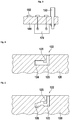
- FIG 4 a detail of the bayonet lock is shown. Basically, this is a side view of a section of the hollow shaft 120.
- the bayonet lock notch 122 is shown in detail.
- This notch preferably has a first section 123 which goes into a direction such that the compression of the spring is increased.
- a second section 124 preferably is under a right angle to the first section. This section can be reached by the bayonet lock protrusion 342 by rotating the locking ring.
- FIG. 5 a detail of another embodiment of a bayonet lock is shown. Basically, this is similar to the previous embodiment, but has a modified second section 126. This second section 126 may have multiple sections with different heights. The bayonet lock protrusion 342 notch may engage with any of these sections resulting in a different position of the locking ring and therefore in different force of the spring 340. Here, by rotating the locking ring, the force may be adjusted.
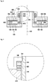
- FIG 6 a second embodiment of a slipring device is shown.
- the slipring device is similar to the slipring device of figure 1 , but has different bearings.
- slide bearings also called friction bearings are used.
- Such bearings have surfaces sliding against each other.
- the ball bearings are replaced by a first slide bearing 410 and a second slide bearing 420.
- Figure 7 shows a detail of the locking ring with bayonet lock and a slide bearing. This is a detail of the previous figure.
- Figure 8 shows a third embodiment of a slipring device.
- the second housing 210 is sliding within first housing 110 and hollow shaft 120.
- the first housing 110 and the hollow shaft 120 may also be one part.
- Figure 9 shows a detail of the locking ring of the previous embodiment.
- slipring device is similar to the slipring device of figure 1 , but has only one ball bearing 620.
- Figure 11 shows a detail of the locking ring of the previous embodiment.
Landscapes
- Snaps, Bayonet Connections, Set Pins, And Snap Rings (AREA)
- Pivots And Pivotal Connections (AREA)
Priority Applications (3)
| Application Number | Priority Date | Filing Date | Title |
|---|---|---|---|
| PCT/EP2020/061044 WO2020249289A1 (fr) | 2018-10-19 | 2020-04-21 | Boîtier à bague collectrice à verrouillage à baïonnette |
| CN202080038758.8A CN113875099B (zh) | 2019-06-14 | 2020-04-21 | 滑环装置 |
| US17/547,408 US11374355B2 (en) | 2019-06-14 | 2021-12-10 | Slipring housing with bayonet lock |
Applications Claiming Priority (1)
| Application Number | Priority Date | Filing Date | Title |
|---|---|---|---|
| EP18201546 | 2018-10-19 |
Publications (2)
| Publication Number | Publication Date |
|---|---|
| EP3641076A1 true EP3641076A1 (fr) | 2020-04-22 |
| EP3641076B1 EP3641076B1 (fr) | 2020-09-30 |
Family
ID=63965147
Family Applications (1)
| Application Number | Title | Priority Date | Filing Date |
|---|---|---|---|
| EP19180216.4A Active EP3641076B1 (fr) | 2018-10-19 | 2019-06-14 | Logement de bague collectrice comportant une serrure à baïonnette |
Country Status (1)
| Country | Link |
|---|---|
| EP (1) | EP3641076B1 (fr) |
Cited By (1)
| Publication number | Priority date | Publication date | Assignee | Title |
|---|---|---|---|---|
| EP4343986A1 (fr) * | 2022-09-26 | 2024-03-27 | Dr. Johannes Heidenhain GmbH | Module de bague collectrice |
Citations (7)
| Publication number | Priority date | Publication date | Assignee | Title |
|---|---|---|---|---|
| CH246799A (de) | 1942-08-31 | 1947-01-31 | Fides Gmbh | Verfahren zur Herstellung eines mehrere axial nebeneinander geschichtete Schleifringe aufweisenden Schleifringkörpers. |
| US4485278A (en) | 1980-10-29 | 1984-11-27 | Schaller Albert R | Device for automatically winding up a feeder cable |
| EP1026794A2 (fr) | 1999-02-08 | 2000-08-09 | Litton Systems, Inc. | Bague collectrice à haute densité |
| US20080192975A1 (en) | 2004-05-21 | 2008-08-14 | Sony Corporation | Headphone, Electronic Device, Cord Winding Device, and Cord Winding Method |
| EP2696443A2 (fr) | 2012-08-06 | 2014-02-12 | Schleifring und Apparatebau GmbH | Boîtier multifonctionel pour bague collectrice |
| EP3096175A2 (fr) | 2015-05-19 | 2016-11-23 | Swarovski Optik Kg | Dispositif optique a distance comprenant un boitier et un accessoire de support |
| EP3316425A1 (fr) | 2016-10-25 | 2018-05-02 | Schleifring GmbH | Module d'une bague collectrice |
-
2019
- 2019-06-14 EP EP19180216.4A patent/EP3641076B1/fr active Active
Patent Citations (7)
| Publication number | Priority date | Publication date | Assignee | Title |
|---|---|---|---|---|
| CH246799A (de) | 1942-08-31 | 1947-01-31 | Fides Gmbh | Verfahren zur Herstellung eines mehrere axial nebeneinander geschichtete Schleifringe aufweisenden Schleifringkörpers. |
| US4485278A (en) | 1980-10-29 | 1984-11-27 | Schaller Albert R | Device for automatically winding up a feeder cable |
| EP1026794A2 (fr) | 1999-02-08 | 2000-08-09 | Litton Systems, Inc. | Bague collectrice à haute densité |
| US20080192975A1 (en) | 2004-05-21 | 2008-08-14 | Sony Corporation | Headphone, Electronic Device, Cord Winding Device, and Cord Winding Method |
| EP2696443A2 (fr) | 2012-08-06 | 2014-02-12 | Schleifring und Apparatebau GmbH | Boîtier multifonctionel pour bague collectrice |
| EP3096175A2 (fr) | 2015-05-19 | 2016-11-23 | Swarovski Optik Kg | Dispositif optique a distance comprenant un boitier et un accessoire de support |
| EP3316425A1 (fr) | 2016-10-25 | 2018-05-02 | Schleifring GmbH | Module d'une bague collectrice |
Cited By (1)
| Publication number | Priority date | Publication date | Assignee | Title |
|---|---|---|---|---|
| EP4343986A1 (fr) * | 2022-09-26 | 2024-03-27 | Dr. Johannes Heidenhain GmbH | Module de bague collectrice |
Also Published As
| Publication number | Publication date |
|---|---|
| EP3641076B1 (fr) | 2020-09-30 |
Similar Documents
| Publication | Publication Date | Title |
|---|---|---|
| US6964578B2 (en) | Cable connector retaining assembly, system, and method of assembling same | |
| US6893267B1 (en) | USB plug with a multi-directional rotation structure | |
| CN102265471B (zh) | 具有改进的电路的rf终接器 | |
| US20010008810A1 (en) | Electrical signal coupling device | |
| US5484294A (en) | Brushless rotary connector | |
| US20060255251A1 (en) | Encoder device and apparatus for gapping and centering an encoder device | |
| JP2007311338A (ja) | 波形ケーブル・インタフェース・インサートを有するコネクタ | |
| US20130025932A1 (en) | Waterproof assembly and device employing the same | |
| EP3641076B1 (fr) | Logement de bague collectrice comportant une serrure à baïonnette | |
| CN106936011A (zh) | 连接器组件及户外通信设备 | |
| US11374355B2 (en) | Slipring housing with bayonet lock | |
| CN106558786A (zh) | 旋转接触件 | |
| JP2530820B2 (ja) | 電話受話器等に適した回転コネクタ | |
| CN108899712B (zh) | 一种电连接器 | |
| JP4751194B2 (ja) | 角度測定装置 | |
| US20130228570A1 (en) | Anti-theft box for electronic device | |
| CN101361237A (zh) | 旋转连接器 | |
| US20200080870A1 (en) | Encoder and rotatable device using same | |
| CN102509955A (zh) | 一种用于连接器的防错插结构 | |
| CN204011884U (zh) | 多轴式端子固定装置 | |
| CN209737645U (zh) | 机械臂关节及具有该机械臂关节的机械臂 | |
| TWI497814B (zh) | 天線旋轉機構 | |
| EP4387012A1 (fr) | Connecteur circulaire | |
| CN106352899B (zh) | 惯性测量单元三自由度快速标定装置 | |
| JP7828818B2 (ja) | ロータリエンコーダおよびトレランスリングを有するアセンブリ |
Legal Events
| Date | Code | Title | Description |
|---|---|---|---|
| PUAI | Public reference made under article 153(3) epc to a published international application that has entered the european phase |
Free format text: ORIGINAL CODE: 0009012 |
|
| STAA | Information on the status of an ep patent application or granted ep patent |
Free format text: STATUS: REQUEST FOR EXAMINATION WAS MADE |
|
| 17P | Request for examination filed |
Effective date: 20190709 |
|
| AK | Designated contracting states |
Kind code of ref document: A1 Designated state(s): AL AT BE BG CH CY CZ DE DK EE ES FI FR GB GR HR HU IE IS IT LI LT LU LV MC MK MT NL NO PL PT RO RS SE SI SK SM TR |
|
| AX | Request for extension of the european patent |
Extension state: BA ME |
|
| GRAP | Despatch of communication of intention to grant a patent |
Free format text: ORIGINAL CODE: EPIDOSNIGR1 |
|
| STAA | Information on the status of an ep patent application or granted ep patent |
Free format text: STATUS: GRANT OF PATENT IS INTENDED |
|
| RIC1 | Information provided on ipc code assigned before grant |
Ipc: H01R 39/64 20060101ALI20200506BHEP Ipc: H01R 39/08 20060101AFI20200506BHEP Ipc: H01R 13/625 20060101ALI20200506BHEP Ipc: H01R 39/14 20060101ALN20200506BHEP Ipc: H01R 13/66 20060101ALN20200506BHEP Ipc: H01R 39/10 20060101ALI20200506BHEP |
|
| INTG | Intention to grant announced |
Effective date: 20200520 |
|
| GRAS | Grant fee paid |
Free format text: ORIGINAL CODE: EPIDOSNIGR3 |
|
| GRAA | (expected) grant |
Free format text: ORIGINAL CODE: 0009210 |
|
| STAA | Information on the status of an ep patent application or granted ep patent |
Free format text: STATUS: THE PATENT HAS BEEN GRANTED |
|
| AK | Designated contracting states |
Kind code of ref document: B1 Designated state(s): AL AT BE BG CH CY CZ DE DK EE ES FI FR GB GR HR HU IE IS IT LI LT LU LV MC MK MT NL NO PL PT RO RS SE SI SK SM TR |
|
| REG | Reference to a national code |
Ref country code: CH Ref legal event code: EP Ref country code: GB Ref legal event code: FG4D |
|
| REG | Reference to a national code |
Ref country code: AT Ref legal event code: REF Ref document number: 1319761 Country of ref document: AT Kind code of ref document: T Effective date: 20201015 |
|
| REG | Reference to a national code |
Ref country code: DE Ref legal event code: R096 Ref document number: 602019000820 Country of ref document: DE |
|
| REG | Reference to a national code |
Ref country code: IE Ref legal event code: FG4D |
|
| PG25 | Lapsed in a contracting state [announced via postgrant information from national office to epo] |
Ref country code: HR Free format text: LAPSE BECAUSE OF FAILURE TO SUBMIT A TRANSLATION OF THE DESCRIPTION OR TO PAY THE FEE WITHIN THE PRESCRIBED TIME-LIMIT Effective date: 20200930 Ref country code: SE Free format text: LAPSE BECAUSE OF FAILURE TO SUBMIT A TRANSLATION OF THE DESCRIPTION OR TO PAY THE FEE WITHIN THE PRESCRIBED TIME-LIMIT Effective date: 20200930 Ref country code: BG Free format text: LAPSE BECAUSE OF FAILURE TO SUBMIT A TRANSLATION OF THE DESCRIPTION OR TO PAY THE FEE WITHIN THE PRESCRIBED TIME-LIMIT Effective date: 20201230 Ref country code: NO Free format text: LAPSE BECAUSE OF FAILURE TO SUBMIT A TRANSLATION OF THE DESCRIPTION OR TO PAY THE FEE WITHIN THE PRESCRIBED TIME-LIMIT Effective date: 20201230 Ref country code: GR Free format text: LAPSE BECAUSE OF FAILURE TO SUBMIT A TRANSLATION OF THE DESCRIPTION OR TO PAY THE FEE WITHIN THE PRESCRIBED TIME-LIMIT Effective date: 20201231 Ref country code: FI Free format text: LAPSE BECAUSE OF FAILURE TO SUBMIT A TRANSLATION OF THE DESCRIPTION OR TO PAY THE FEE WITHIN THE PRESCRIBED TIME-LIMIT Effective date: 20200930 |
|
| REG | Reference to a national code |
Ref country code: AT Ref legal event code: MK05 Ref document number: 1319761 Country of ref document: AT Kind code of ref document: T Effective date: 20200930 |
|
| PG25 | Lapsed in a contracting state [announced via postgrant information from national office to epo] |
Ref country code: LV Free format text: LAPSE BECAUSE OF FAILURE TO SUBMIT A TRANSLATION OF THE DESCRIPTION OR TO PAY THE FEE WITHIN THE PRESCRIBED TIME-LIMIT Effective date: 20200930 Ref country code: RS Free format text: LAPSE BECAUSE OF FAILURE TO SUBMIT A TRANSLATION OF THE DESCRIPTION OR TO PAY THE FEE WITHIN THE PRESCRIBED TIME-LIMIT Effective date: 20200930 |
|
| REG | Reference to a national code |
Ref country code: NL Ref legal event code: MP Effective date: 20200930 |
|
| REG | Reference to a national code |
Ref country code: LT Ref legal event code: MG4D |
|
| PG25 | Lapsed in a contracting state [announced via postgrant information from national office to epo] |
Ref country code: LT Free format text: LAPSE BECAUSE OF FAILURE TO SUBMIT A TRANSLATION OF THE DESCRIPTION OR TO PAY THE FEE WITHIN THE PRESCRIBED TIME-LIMIT Effective date: 20200930 Ref country code: SM Free format text: LAPSE BECAUSE OF FAILURE TO SUBMIT A TRANSLATION OF THE DESCRIPTION OR TO PAY THE FEE WITHIN THE PRESCRIBED TIME-LIMIT Effective date: 20200930 Ref country code: EE Free format text: LAPSE BECAUSE OF FAILURE TO SUBMIT A TRANSLATION OF THE DESCRIPTION OR TO PAY THE FEE WITHIN THE PRESCRIBED TIME-LIMIT Effective date: 20200930 Ref country code: RO Free format text: LAPSE BECAUSE OF FAILURE TO SUBMIT A TRANSLATION OF THE DESCRIPTION OR TO PAY THE FEE WITHIN THE PRESCRIBED TIME-LIMIT Effective date: 20200930 Ref country code: PT Free format text: LAPSE BECAUSE OF FAILURE TO SUBMIT A TRANSLATION OF THE DESCRIPTION OR TO PAY THE FEE WITHIN THE PRESCRIBED TIME-LIMIT Effective date: 20210201 Ref country code: CZ Free format text: LAPSE BECAUSE OF FAILURE TO SUBMIT A TRANSLATION OF THE DESCRIPTION OR TO PAY THE FEE WITHIN THE PRESCRIBED TIME-LIMIT Effective date: 20200930 |
|
| PG25 | Lapsed in a contracting state [announced via postgrant information from national office to epo] |
Ref country code: PL Free format text: LAPSE BECAUSE OF FAILURE TO SUBMIT A TRANSLATION OF THE DESCRIPTION OR TO PAY THE FEE WITHIN THE PRESCRIBED TIME-LIMIT Effective date: 20200930 Ref country code: IS Free format text: LAPSE BECAUSE OF FAILURE TO SUBMIT A TRANSLATION OF THE DESCRIPTION OR TO PAY THE FEE WITHIN THE PRESCRIBED TIME-LIMIT Effective date: 20210130 Ref country code: AL Free format text: LAPSE BECAUSE OF FAILURE TO SUBMIT A TRANSLATION OF THE DESCRIPTION OR TO PAY THE FEE WITHIN THE PRESCRIBED TIME-LIMIT Effective date: 20200930 Ref country code: AT Free format text: LAPSE BECAUSE OF FAILURE TO SUBMIT A TRANSLATION OF THE DESCRIPTION OR TO PAY THE FEE WITHIN THE PRESCRIBED TIME-LIMIT Effective date: 20200930 Ref country code: ES Free format text: LAPSE BECAUSE OF FAILURE TO SUBMIT A TRANSLATION OF THE DESCRIPTION OR TO PAY THE FEE WITHIN THE PRESCRIBED TIME-LIMIT Effective date: 20200930 |
|
| PG25 | Lapsed in a contracting state [announced via postgrant information from national office to epo] |
Ref country code: NL Free format text: LAPSE BECAUSE OF FAILURE TO SUBMIT A TRANSLATION OF THE DESCRIPTION OR TO PAY THE FEE WITHIN THE PRESCRIBED TIME-LIMIT Effective date: 20200930 Ref country code: SK Free format text: LAPSE BECAUSE OF FAILURE TO SUBMIT A TRANSLATION OF THE DESCRIPTION OR TO PAY THE FEE WITHIN THE PRESCRIBED TIME-LIMIT Effective date: 20200930 |
|
| REG | Reference to a national code |
Ref country code: DE Ref legal event code: R097 Ref document number: 602019000820 Country of ref document: DE |
|
| PLBE | No opposition filed within time limit |
Free format text: ORIGINAL CODE: 0009261 |
|
| STAA | Information on the status of an ep patent application or granted ep patent |
Free format text: STATUS: NO OPPOSITION FILED WITHIN TIME LIMIT |
|
| PG25 | Lapsed in a contracting state [announced via postgrant information from national office to epo] |
Ref country code: DK Free format text: LAPSE BECAUSE OF FAILURE TO SUBMIT A TRANSLATION OF THE DESCRIPTION OR TO PAY THE FEE WITHIN THE PRESCRIBED TIME-LIMIT Effective date: 20200930 |
|
| 26N | No opposition filed |
Effective date: 20210701 |
|
| PG25 | Lapsed in a contracting state [announced via postgrant information from national office to epo] |
Ref country code: IT Free format text: LAPSE BECAUSE OF FAILURE TO SUBMIT A TRANSLATION OF THE DESCRIPTION OR TO PAY THE FEE WITHIN THE PRESCRIBED TIME-LIMIT Effective date: 20200930 |
|
| PG25 | Lapsed in a contracting state [announced via postgrant information from national office to epo] |
Ref country code: SI Free format text: LAPSE BECAUSE OF FAILURE TO SUBMIT A TRANSLATION OF THE DESCRIPTION OR TO PAY THE FEE WITHIN THE PRESCRIBED TIME-LIMIT Effective date: 20200930 |
|
| PG25 | Lapsed in a contracting state [announced via postgrant information from national office to epo] |
Ref country code: MC Free format text: LAPSE BECAUSE OF FAILURE TO SUBMIT A TRANSLATION OF THE DESCRIPTION OR TO PAY THE FEE WITHIN THE PRESCRIBED TIME-LIMIT Effective date: 20200930 |
|
| REG | Reference to a national code |
Ref country code: BE Ref legal event code: MM Effective date: 20210630 |
|
| PG25 | Lapsed in a contracting state [announced via postgrant information from national office to epo] |
Ref country code: LU Free format text: LAPSE BECAUSE OF NON-PAYMENT OF DUE FEES Effective date: 20210614 |
|
| PG25 | Lapsed in a contracting state [announced via postgrant information from national office to epo] |
Ref country code: IE Free format text: LAPSE BECAUSE OF NON-PAYMENT OF DUE FEES Effective date: 20210614 |
|
| PG25 | Lapsed in a contracting state [announced via postgrant information from national office to epo] |
Ref country code: IS Free format text: LAPSE BECAUSE OF FAILURE TO SUBMIT A TRANSLATION OF THE DESCRIPTION OR TO PAY THE FEE WITHIN THE PRESCRIBED TIME-LIMIT Effective date: 20210130 |
|
| PG25 | Lapsed in a contracting state [announced via postgrant information from national office to epo] |
Ref country code: BE Free format text: LAPSE BECAUSE OF NON-PAYMENT OF DUE FEES Effective date: 20210630 |
|
| REG | Reference to a national code |
Ref country code: CH Ref legal event code: PL |
|
| PG25 | Lapsed in a contracting state [announced via postgrant information from national office to epo] |
Ref country code: LI Free format text: LAPSE BECAUSE OF NON-PAYMENT OF DUE FEES Effective date: 20220630 Ref country code: CH Free format text: LAPSE BECAUSE OF NON-PAYMENT OF DUE FEES Effective date: 20220630 |
|
| PG25 | Lapsed in a contracting state [announced via postgrant information from national office to epo] |
Ref country code: CY Free format text: LAPSE BECAUSE OF FAILURE TO SUBMIT A TRANSLATION OF THE DESCRIPTION OR TO PAY THE FEE WITHIN THE PRESCRIBED TIME-LIMIT Effective date: 20200930 |
|
| PG25 | Lapsed in a contracting state [announced via postgrant information from national office to epo] |
Ref country code: HU Free format text: LAPSE BECAUSE OF FAILURE TO SUBMIT A TRANSLATION OF THE DESCRIPTION OR TO PAY THE FEE WITHIN THE PRESCRIBED TIME-LIMIT; INVALID AB INITIO Effective date: 20190614 |
|
| PG25 | Lapsed in a contracting state [announced via postgrant information from national office to epo] |
Ref country code: MK Free format text: LAPSE BECAUSE OF FAILURE TO SUBMIT A TRANSLATION OF THE DESCRIPTION OR TO PAY THE FEE WITHIN THE PRESCRIBED TIME-LIMIT Effective date: 20200930 |
|
| PG25 | Lapsed in a contracting state [announced via postgrant information from national office to epo] |
Ref country code: TR Free format text: LAPSE BECAUSE OF FAILURE TO SUBMIT A TRANSLATION OF THE DESCRIPTION OR TO PAY THE FEE WITHIN THE PRESCRIBED TIME-LIMIT Effective date: 20200930 |
|
| PG25 | Lapsed in a contracting state [announced via postgrant information from national office to epo] |
Ref country code: MT Free format text: LAPSE BECAUSE OF FAILURE TO SUBMIT A TRANSLATION OF THE DESCRIPTION OR TO PAY THE FEE WITHIN THE PRESCRIBED TIME-LIMIT Effective date: 20200930 |
|
| PGFP | Annual fee paid to national office [announced via postgrant information from national office to epo] |
Ref country code: DE Payment date: 20250618 Year of fee payment: 7 |
|
| PGFP | Annual fee paid to national office [announced via postgrant information from national office to epo] |
Ref country code: GB Payment date: 20250620 Year of fee payment: 7 |
|
| PGFP | Annual fee paid to national office [announced via postgrant information from national office to epo] |
Ref country code: FR Payment date: 20250626 Year of fee payment: 7 |