EP2696443A2 - Boîtier multifonctionel pour bague collectrice - Google Patents
Boîtier multifonctionel pour bague collectrice Download PDFInfo
- Publication number
- EP2696443A2 EP2696443A2 EP13175948.2A EP13175948A EP2696443A2 EP 2696443 A2 EP2696443 A2 EP 2696443A2 EP 13175948 A EP13175948 A EP 13175948A EP 2696443 A2 EP2696443 A2 EP 2696443A2
- Authority
- EP
- European Patent Office
- Prior art keywords
- slip ring
- module
- space
- brush
- housing
- Prior art date
- Legal status (The legal status is an assumption and is not a legal conclusion. Google has not performed a legal analysis and makes no representation as to the accuracy of the status listed.)
- Granted
Links
Images


Classifications
-
- H—ELECTRICITY
- H01—ELECTRIC ELEMENTS
- H01R—ELECTRICALLY-CONDUCTIVE CONNECTIONS; STRUCTURAL ASSOCIATIONS OF A PLURALITY OF MUTUALLY-INSULATED ELECTRICAL CONNECTING ELEMENTS; COUPLING DEVICES; CURRENT COLLECTORS
- H01R13/00—Details of coupling devices of the kinds covered by groups H01R12/70 or H01R24/00 - H01R33/00
- H01R13/46—Bases; Cases
-
- H—ELECTRICITY
- H01—ELECTRIC ELEMENTS
- H01R—ELECTRICALLY-CONDUCTIVE CONNECTIONS; STRUCTURAL ASSOCIATIONS OF A PLURALITY OF MUTUALLY-INSULATED ELECTRICAL CONNECTING ELEMENTS; COUPLING DEVICES; CURRENT COLLECTORS
- H01R39/00—Rotary current collectors, distributors or interrupters
- H01R39/02—Details for dynamo electric machines
- H01R39/08—Slip-rings
Definitions
- the invention relates to a housing for a slip ring assembly and a slip ring assembly.
- electrical signals can be transmitted by means of sliding contacts or contactless between mutually rotatable parts.
- the EP 0662736 A discloses a slip ring assembly in which a brush having a plurality of wires of electrically conductive material runs in a V-groove of a sliding track of electrically conductive material.
- the galvanic contact between the slideway and the wires electrical current can be transmitted.
- the housing is cylindrical and must be disassembled to gain access to the slip ring components. When reassembling, the assembly must be adjusted for precise alignment of the brushes with the sanding paths.
- this slip ring arrangement can only be maintained by a workshop which has the corresponding adjustment devices available. Even simple maintenance work, such as a re-oiling of the slideways also necessarily require such a workshop.
- DE 1489080 A discloses a slip ring assembly in which brushes in the form of solid strands run in grooves of a slideway. Again, a cylindrical housing is disclosed which must be disassembled to gain access to the slip ring components.
- EP 1154 920 B1 is a motor-pump unit disclosed in which a separate rule or. Control circuit is provided in a separate housing.
- the DE 1928597 discloses an electric machine having an easily replaceable brush holder assembly accessible through its own service door.
- the connection terminals are under another operating door.
- the cooling air flow is directed via the terminals to the brush holder assembly.
- the invention has for its object to design a slip ring housing and a slip ring assembly such that an easy access to the slip ring components is possible, which also allows maintenance without re-adjustment of the slip ring assembly.
- a slip ring assembly having a slip ring housing has at least four sides, preferably exactly four sides, which are preferably arranged at a right angle to the respective adjacent sides. It encloses at least one slip ring module with a rotation axis, which is rotatable about this rotation axis, and at least one brush block. The sides are preferably arranged parallel to the axis of rotation. This allows a simple, space-saving and modular design can be achieved.
- the individual pages fulfill individual functions and are preferably designed for access by certain groups of people. The separation of functions results in a simple and easy-to-maintain arrangement that also eliminates errors during assembly and maintenance work helps avoid. Thus, certain covers that close the access to individual pages can be closed with different means.
- the first side is preferably a mounting wall, by means of which the slip ring housing can be fastened.
- the entire slip ring housing for example, be attached to the rotating or stationary part of a device or even a machine.
- an additional torque bridge To accommodate the torque can still be provided an additional torque bridge.
- the torque bridge transmits only the torque and is otherwise freely movable to avoid overdetermination. Since the bearings precisely define the axis of rotation in the bearing housing, only a torque may be introduced by the torque bridge. Additional and especially lateral forces are not desired.
- the torque bridge is, for example, a rod which is received in a thread of the module or bearing housing and is held or taken by the customer by a mechanical stop.
- the mounting wall has a receptacle for a clamping device in which the slip ring housing can be held during at least one manufacturing step.
- the second side has an opening to a brush carrier space through which the brush carriers are accessible.
- This brush carrier space is preferably only accessible for qualified maintenance personnel. For example, a brush carrier with a defective brush can be exchanged from this brush carrier space.
- the individual brush holders are connected via connectors by cables with external connectors, wherein the cables are guided outside of the brush carrier space.
- the connectors are arranged so that they allow a direct connection from outside the brush carrier space. This allows the individual brush holders to be replaced without any further wiring work.
- the brush carrier space can preferably be sealed off from the slip ring module and is particularly preferably sealed off from it.
- the brush carrier space can preferably be sealed off from the slip ring module and is particularly preferably sealed off from it.
- the penetration of dust and / or particles into the space of the module and the penetration of electrically conductive abrasion, in particular of carbon brushes in the brush carrier space can be prevented.
- the electrical wiring for electrical contacting and in particular for the parallel connection of a plurality of brushes in the brush carrier space and not in the space of the slip ring module is preferably mounted. If the brush carrier space is free of electrically conductive impurities, smaller insulation distances can be used here.
- the third side has an opening to a connection space through which the electrical connections are accessible.
- this connection space preferably the cable for connecting the brush holder with external connectors are performed. It can easily do maintenance work such as configuration changes and / or replacement of the cables or external connectors are made, without coming in contact with slip ring module in and / or brush holders. Thus, work in this area could also be carried out by persons who are not qualified to work on the slip ring. Often there is the problem that when closing a cover of a slip ring housing a plurality of cables must be accommodated in a confined space.
- the cables may come too close to moving slip ring components and possibly contact moving components, which may lead to damage to the insulation and possibly to a fault such as interruption and / or short circuit.
- the cables could mechanical load slip ring components, for example, press on a brush holder and deform it. As a result, a brush could be pressed laterally out of the web and / or its pressure force could be changed. This can lead to higher wear or premature failure.
- the inventive design with a separate connection space any contact of the cable with slip ring module and / or brush holders is avoided. This can be safely prevented even with strong compression of the cable influencing these slip ring components, resulting in a higher reliability and quality of the arrangement.
- connection space may preferably be dust-tight with respect to the slip ring module be sealed or is preferably sealed. This can still be a seal against the brush carrier space, if this is not self-sealed against the module.
- a cooling air flow over the slip ring arrangement can be performed without the particles contaminated by slip ring abrasion cooling air enters the terminal compartment.
- the fourth side provides an opening to a module space in which at least one slip ring module is arranged.
- the slip ring modules are accessible from one side, which faces away from the side of the brush holder and is preferably arranged opposite to the side of the brush holder or of the brush carrier space.
- there is no access to the brushes Thus, they can not be damaged during maintenance work on the slip ring modules.
- By rotating the slip ring modules relative to the slip ring housing By rotating the slip ring modules relative to the slip ring housing, however, they can all around be checked and maintained. For example, a lubrication and / or cleaning and / or machining of the surface of the sliding tracks of the slip ring modules can be performed.
- a slip ring arrangement comprises at least one slip ring module and at least one corresponding brush carrier. These are housed in a previously described slip ring housing.
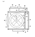
- FIG. 1 a device according to the invention is shown in plan view.
- the slip ring module 10 is preferably by means of a module carrier 11 to a shaft 12 rotatably mounted relative to the slip ring housing 30.
- the slip ring module 10 rotates about the shaft, the center of which represents the axis of rotation of the assembly.
- In engagement with the at least one slip ring module 10 is at least a first brush 21 and a second brush 22, which are preferably held by at least one brush holder 20 and are particularly preferably contacted by means of this.
- the at least one brush holder 20 is connected by at least one connector 23 via at least one cable 24 with at least one external connector 62.
- the slip ring housing preferably has four sides, which are particularly preferably arranged at a right angle to their adjacent sides.
- a first side preferably comprises a mounting wall 40, which particularly preferably has at least one fastening element 41 for fastening the slip ring housing 30.
- a second side preferably comprises an opening to a brush carrier space 50, which is preferably closable by a brush carrier cover 51.
- a third side preferably comprises an opening to a connection space 60, which is preferably closable by a connection cover 61.
- This terminal cover 61 is preferably used as a carrier for external connectors, such as a first external connector 62 and a second external connector 63.
- external connectors such as a first external connector 62 and a second external connector 63.
- at least one cable gland 64 intended.
- This may be a simple opening, which is preferably sealed with a sealant. Particular preference is given to using a permanently elastic sealing compound, for example silicone.
- a fourth side preferably comprises an opening to a module space 70, in which the slip ring module 10 is arranged. This opening is preferably closed with a module cover 71.
- the slip ring housing is preferably made of a metal such as zinc or aluminum, particularly preferably produced by injection molding.
- the housing may also comprise a plastic material, particularly preferably a fiber-reinforced plastic material reinforced, for example, by glass fibers and / or carbon fibers.
- a seal 31 is provided for sealing the covers 51, 61 and 71. This can be a circumferential seal, for example a sealing cord or even an applied and / or molded plastic and / or rubber seal.
- FIG. 2 a side view of the mounting wall 40 is shown.
- This mounting wall 40 preferably has at least one fastening element 41.
- mounting holes such as a first mounting hole 42 and a second mounting hole 43 are provided. These have particularly preferably an internal thread.
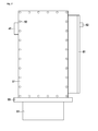
- FIG. 3 a side view of the brush carrier space 50 is shown.
- individual brush holders 20, 25, 26 are preferably fastened by fastening screws 89.
- the distance of the individual brush holder preferably corresponds to the distance of the individual slip ring modules.
- the brush carriers have conductor tracks 81 for connecting brush contacts 80 to at least one plug connector 23.
- recesses 82 can be provided in the brush holder, through which access to the brushes is possible.
- a connector is provided per brush holder. But it can also be multiple connectors. It is particularly favorable if the plug connector is arranged directly after the connection space, so that no connection cables run inside the brush support space.
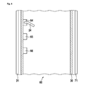
- connection space 60 a side view of the connection space 60 is shown.
- a first grommet 64 a second grommet 65 and a third cable gland 66 can be seen, which lead to the corresponding brush holders 20, 25 and 26.
- a cable 24 is shown here, which leads to the plug connector 23 of the brush holder 20.
- a separate cable bushing is provided for each brush holder.
- the cable glands are adapted to the required cable cross sections and / or sizes of the connector.
- the cable bushings are sealed in order to achieve a separation of the connection space 60 from the brush carrier space 50.
- the connection space 60 can also have connection terminals for connection. In this case, at least a part of the external connector 62,63 could be omitted.
- FIG. 5 a side view of the module space 70 is shown.
- three slip ring modules, a first slip ring module 10, a second slip ring module 15 and a third slip ring module 16 are shown here by way of example.
- the slip ring modules have at least one sliding track.
- the slip ring module 10 has three grinding paths, a first grinding path 17, a second grinding path 18 and a third grinding path 19. It is particularly preferred if individual modules with three slideways or a slideway number corresponding to an integer multiple of 3 are used.
- FIG. 6 is a further side view of the brush carrier space 50 shown, in which the terminal space 60 is cut.
- FIG. 7 an overall view of the arrangement is shown.
- This shows a closed brush holder cover 51, which is preferably firmly closed by fastening screws 52.
- a bearing housing 90 is shown in which preferably a bearing, which is a Rotation of the modules relative to the slip ring housing allows, is located.
- a module connection housing 91 below the bearing housing 90 is, rotationally fixed to the modules connected, a module connection housing 91, in which the slip ring modules can be contacted. So may optionally be located in this housing terminals and / or connectors.
- the module connection housing is preferably round. In an alternative embodiment, it is rectangular, preferably square, wherein particularly preferably an arrangement is symmetrical to the axis of rotation.
- Connectors for connecting the module connection housing can optionally be arranged radially or on the axial side of the housing.
- a terminal box with cable strain relief can be mounted inside or on the module connection housing.
- the module junction box itself is an important part of the assembly because it terminates the slip ring housing or slip ring assembly on the side of the module. Without this module connection housing, the slip ring housing would be open on one side, so that the functionality of the slip ring housing would not exist.
- the upper part comprising the brush carrier cover 51 and the terminal cover 61 are rotatably connected to the module connector housing 91 via the bearing housing 90. Together with the module connection housing, the at least one slip ring module 10 is rotatable in the interior of the arrangement. This is the at least one brush holder 20 with the brush holder cover 51 and the terminal cover 61 together rotatable.
Landscapes
- Motor Or Generator Current Collectors (AREA)
Priority Applications (2)
| Application Number | Priority Date | Filing Date | Title |
|---|---|---|---|
| EP13175948.2A EP2696443B1 (fr) | 2012-08-06 | 2013-07-10 | Boîtier multifonctionel pour bague collectrice |
| CN201310337370.XA CN103579881B (zh) | 2012-08-06 | 2013-08-05 | 多功能集电环壳体 |
Applications Claiming Priority (2)
| Application Number | Priority Date | Filing Date | Title |
|---|---|---|---|
| EP12179431.7A EP2696442A1 (fr) | 2012-08-06 | 2012-08-06 | Boîtier multifonctionel pour bague collectrice |
| EP13175948.2A EP2696443B1 (fr) | 2012-08-06 | 2013-07-10 | Boîtier multifonctionel pour bague collectrice |
Publications (3)
| Publication Number | Publication Date |
|---|---|
| EP2696443A2 true EP2696443A2 (fr) | 2014-02-12 |
| EP2696443A3 EP2696443A3 (fr) | 2014-08-06 |
| EP2696443B1 EP2696443B1 (fr) | 2015-11-04 |
Family
ID=48747480
Family Applications (2)
| Application Number | Title | Priority Date | Filing Date |
|---|---|---|---|
| EP12179431.7A Withdrawn EP2696442A1 (fr) | 2012-08-06 | 2012-08-06 | Boîtier multifonctionel pour bague collectrice |
| EP13175948.2A Active EP2696443B1 (fr) | 2012-08-06 | 2013-07-10 | Boîtier multifonctionel pour bague collectrice |
Family Applications Before (1)
| Application Number | Title | Priority Date | Filing Date |
|---|---|---|---|
| EP12179431.7A Withdrawn EP2696442A1 (fr) | 2012-08-06 | 2012-08-06 | Boîtier multifonctionel pour bague collectrice |
Country Status (4)
| Country | Link |
|---|---|
| EP (2) | EP2696442A1 (fr) |
| CN (1) | CN103579881B (fr) |
| DK (1) | DK2696443T3 (fr) |
| ES (1) | ES2558464T3 (fr) |
Cited By (2)
| Publication number | Priority date | Publication date | Assignee | Title |
|---|---|---|---|---|
| EP3641076A1 (fr) | 2018-10-19 | 2020-04-22 | Schleifring GmbH | Logement de bague collectrice comportant une serrure à baïonnette |
| US11374355B2 (en) | 2019-06-14 | 2022-06-28 | Schleifring Gmbh | Slipring housing with bayonet lock |
Families Citing this family (2)
| Publication number | Priority date | Publication date | Assignee | Title |
|---|---|---|---|---|
| CN106793985B (zh) | 2014-10-07 | 2020-11-10 | 史莱福灵有限公司 | 具有由填充的smc和/或bmc材料构成的屏蔽器件的旋转式传输器 |
| CN109638588B (zh) * | 2018-12-29 | 2024-01-30 | 威海威高齐全医疗设备有限公司 | 一种可插拔式滑环 |
Citations (4)
| Publication number | Priority date | Publication date | Assignee | Title |
|---|---|---|---|---|
| DE1928597U (de) | 1962-12-24 | 1965-12-09 | Siemens Ag | Buerstenhalteranordnung. |
| DE1489080A1 (de) | 1963-08-30 | 1969-01-16 | Litton Industries Inc | Schleifkontaktanordnung |
| EP0662736A1 (fr) | 1994-01-10 | 1995-07-12 | Air Precision S.A. | Collecteur électrique tournant à balais multibrins |
| EP1154920B1 (fr) | 1999-03-02 | 2002-07-17 | Siemens Aktiengesellschaft | Ensemble moteur-organe d'entrainement, notamment ensemble moteur-pompe pour un dispositif antiblocage de vehicule automobile |
Family Cites Families (5)
| Publication number | Priority date | Publication date | Assignee | Title |
|---|---|---|---|---|
| CN1178339C (zh) * | 2002-05-30 | 2004-12-01 | 武汉华之洋光电系统有限责任公司 | 一种旋转电接触装置 |
| CN200987105Y (zh) * | 2006-12-30 | 2007-12-05 | 黄洪权 | 绕线转子三相异步电动机 |
| CN101227129B (zh) * | 2007-10-08 | 2011-09-07 | 南阳防爆集团有限公司 | 大容量隐极套片式同步发电机 |
| CN201601371U (zh) * | 2009-01-20 | 2010-10-06 | 长沙电机厂有限责任公司 | 一种内馈电机的集电环装置 |
| DE102010050469A1 (de) * | 2010-11-04 | 2012-05-10 | Ltn Servotechnik Gmbh | Schleifringeinheit und Verwendung der Schleifringeinheit in einer Windkraftanlage |
-
2012
- 2012-08-06 EP EP12179431.7A patent/EP2696442A1/fr not_active Withdrawn
-
2013
- 2013-07-10 DK DK13175948.2T patent/DK2696443T3/en active
- 2013-07-10 ES ES13175948.2T patent/ES2558464T3/es active Active
- 2013-07-10 EP EP13175948.2A patent/EP2696443B1/fr active Active
- 2013-08-05 CN CN201310337370.XA patent/CN103579881B/zh active Active
Patent Citations (4)
| Publication number | Priority date | Publication date | Assignee | Title |
|---|---|---|---|---|
| DE1928597U (de) | 1962-12-24 | 1965-12-09 | Siemens Ag | Buerstenhalteranordnung. |
| DE1489080A1 (de) | 1963-08-30 | 1969-01-16 | Litton Industries Inc | Schleifkontaktanordnung |
| EP0662736A1 (fr) | 1994-01-10 | 1995-07-12 | Air Precision S.A. | Collecteur électrique tournant à balais multibrins |
| EP1154920B1 (fr) | 1999-03-02 | 2002-07-17 | Siemens Aktiengesellschaft | Ensemble moteur-organe d'entrainement, notamment ensemble moteur-pompe pour un dispositif antiblocage de vehicule automobile |
Cited By (2)
| Publication number | Priority date | Publication date | Assignee | Title |
|---|---|---|---|---|
| EP3641076A1 (fr) | 2018-10-19 | 2020-04-22 | Schleifring GmbH | Logement de bague collectrice comportant une serrure à baïonnette |
| US11374355B2 (en) | 2019-06-14 | 2022-06-28 | Schleifring Gmbh | Slipring housing with bayonet lock |
Also Published As
| Publication number | Publication date |
|---|---|
| EP2696443B1 (fr) | 2015-11-04 |
| EP2696442A1 (fr) | 2014-02-12 |
| CN103579881B (zh) | 2016-12-28 |
| EP2696443A3 (fr) | 2014-08-06 |
| DK2696443T3 (en) | 2016-02-01 |
| CN103579881A (zh) | 2014-02-12 |
| ES2558464T3 (es) | 2016-02-04 |
Similar Documents
| Publication | Publication Date | Title |
|---|---|---|
| EP3884742B1 (fr) | Module de base et module fonctionnel pour un système d'armoire de distribution | |
| DE102008022052A1 (de) | Anschlussdose, insbesondere für Solarmodule | |
| EP2696443B1 (fr) | Boîtier multifonctionel pour bague collectrice | |
| DE202014101430U1 (de) | Als Kupplung oder Stecker ausgebildete Steckvorrichtung | |
| DE102019212980A1 (de) | Elektrische Maschine mit einer Hochspannungsanschlussanordnung und einer Sicherheitssperreinrichtung | |
| EP3817156A1 (fr) | Connecteur enfichable permettant de fixer un état emboité | |
| DE3447826C2 (de) | Elektro-Außenläufermotor | |
| EP3842187A1 (fr) | Dispositif de raccordement d'un câble | |
| EP0919076A1 (fr) | Installation a haute tension isolee par gas, encapsulee et pourvue d'un composant de connexion cloisonne | |
| DE102015206800B4 (de) | Elektrischer Zentralausrücker mit in Träger gehaltertem Stecker und Hybridmodul mit solchem Aktor | |
| DE102014215058A1 (de) | Anschlussvorrichtung zum Anschließen elektrischer Leitungen und Verfahren zur Montage einer derartigen Anschlussvorrichtung | |
| EP0678953B1 (fr) | Terminaison de câble pour un appareillage de commutation blindé métallique à haute tension et à isolement gazeux | |
| EP3724901B1 (fr) | Traversée haute tension, dispositif électrique ayant une traversée haute tension et procédé de fabrication du dispositif électrique | |
| EP3479073A1 (fr) | Transducteur de mesure pour les techniques de mesure haute tension | |
| DE102011087788A1 (de) | Elektrische Maschine | |
| DE202016104361U1 (de) | Elektrische Steckverbindung für Motorrollen | |
| EP1950770B1 (fr) | Isolateur | |
| DE102020209064B4 (de) | Elektrischer Stecker mit einer kabelseitig einschiebbar ausgestalteten elektrischen Sicherung | |
| EP1336228B1 (fr) | Mecanisme de commande pour appareillages electriques | |
| EP0073423B1 (fr) | Element de liaison d'un conducteur isolé par un corps solide | |
| EP2466706A2 (fr) | Armoire électrique pour le fonctionnement d'une installation de commutation à moyenne ou haute tension | |
| DE102015226027A1 (de) | Öldichte elektrische Anschlussvorrichtung | |
| DE202009005412U1 (de) | Einrichtung zur Verbindung zweier ein- oder mehrpoliger elektrischer Kabel miteinander | |
| EP3020975A1 (fr) | Appareil a vide | |
| EP4384422B1 (fr) | Dispositif et procédé pour établir une connexion électrique entre un accumulateur d'énergie de traction électrique et un système électrique de véhicule à haute tension pour un véhicule à moteur |
Legal Events
| Date | Code | Title | Description |
|---|---|---|---|
| AK | Designated contracting states |
Kind code of ref document: A2 Designated state(s): AL AT BE BG CH CY CZ DE DK EE ES FI FR GB GR HR HU IE IS IT LI LT LU LV MC MK MT NL NO PL PT RO RS SE SI SK SM TR |
|
| AX | Request for extension of the european patent |
Extension state: BA ME |
|
| PUAI | Public reference made under article 153(3) epc to a published international application that has entered the european phase |
Free format text: ORIGINAL CODE: 0009012 |
|
| PUAL | Search report despatched |
Free format text: ORIGINAL CODE: 0009013 |
|
| AK | Designated contracting states |
Kind code of ref document: A3 Designated state(s): AL AT BE BG CH CY CZ DE DK EE ES FI FR GB GR HR HU IE IS IT LI LT LU LV MC MK MT NL NO PL PT RO RS SE SI SK SM TR |
|
| AX | Request for extension of the european patent |
Extension state: BA ME |
|
| RIC1 | Information provided on ipc code assigned before grant |
Ipc: H01R 39/08 20060101ALI20140702BHEP Ipc: H01R 13/46 20060101AFI20140702BHEP |
|
| 17P | Request for examination filed |
Effective date: 20141020 |
|
| RBV | Designated contracting states (corrected) |
Designated state(s): AL AT BE BG CH CY CZ DE DK EE ES FI FR GB GR HR HU IE IS IT LI LT LU LV MC MK MT NL NO PL PT RO RS SE SI SK SM TR |
|
| GRAP | Despatch of communication of intention to grant a patent |
Free format text: ORIGINAL CODE: EPIDOSNIGR1 |
|
| INTG | Intention to grant announced |
Effective date: 20150313 |
|
| GRAP | Despatch of communication of intention to grant a patent |
Free format text: ORIGINAL CODE: EPIDOSNIGR1 |
|
| INTG | Intention to grant announced |
Effective date: 20150818 |
|
| GRAS | Grant fee paid |
Free format text: ORIGINAL CODE: EPIDOSNIGR3 |
|
| GRAA | (expected) grant |
Free format text: ORIGINAL CODE: 0009210 |
|
| AK | Designated contracting states |
Kind code of ref document: B1 Designated state(s): AL AT BE BG CH CY CZ DE DK EE ES FI FR GB GR HR HU IE IS IT LI LT LU LV MC MK MT NL NO PL PT RO RS SE SI SK SM TR |
|
| REG | Reference to a national code |
Ref country code: GB Ref legal event code: FG4D Free format text: NOT ENGLISH |
|
| REG | Reference to a national code |
Ref country code: CH Ref legal event code: EP |
|
| REG | Reference to a national code |
Ref country code: AT Ref legal event code: REF Ref document number: 759766 Country of ref document: AT Kind code of ref document: T Effective date: 20151115 |
|
| REG | Reference to a national code |
Ref country code: IE Ref legal event code: FG4D Free format text: LANGUAGE OF EP DOCUMENT: GERMAN |
|
| REG | Reference to a national code |
Ref country code: DE Ref legal event code: R096 Ref document number: 502013001436 Country of ref document: DE |
|
| REG | Reference to a national code |
Ref country code: DK Ref legal event code: T3 Effective date: 20160129 |
|
| REG | Reference to a national code |
Ref country code: ES Ref legal event code: FG2A Ref document number: 2558464 Country of ref document: ES Kind code of ref document: T3 Effective date: 20160204 |
|
| REG | Reference to a national code |
Ref country code: NL Ref legal event code: MP Effective date: 20151104 |
|
| REG | Reference to a national code |
Ref country code: LT Ref legal event code: MG4D |
|
| PG25 | Lapsed in a contracting state [announced via postgrant information from national office to epo] |
Ref country code: NO Free format text: LAPSE BECAUSE OF FAILURE TO SUBMIT A TRANSLATION OF THE DESCRIPTION OR TO PAY THE FEE WITHIN THE PRESCRIBED TIME-LIMIT Effective date: 20160204 Ref country code: LT Free format text: LAPSE BECAUSE OF FAILURE TO SUBMIT A TRANSLATION OF THE DESCRIPTION OR TO PAY THE FEE WITHIN THE PRESCRIBED TIME-LIMIT Effective date: 20151104 Ref country code: NL Free format text: LAPSE BECAUSE OF FAILURE TO SUBMIT A TRANSLATION OF THE DESCRIPTION OR TO PAY THE FEE WITHIN THE PRESCRIBED TIME-LIMIT Effective date: 20151104 Ref country code: IT Free format text: LAPSE BECAUSE OF FAILURE TO SUBMIT A TRANSLATION OF THE DESCRIPTION OR TO PAY THE FEE WITHIN THE PRESCRIBED TIME-LIMIT Effective date: 20151104 Ref country code: IS Free format text: LAPSE BECAUSE OF FAILURE TO SUBMIT A TRANSLATION OF THE DESCRIPTION OR TO PAY THE FEE WITHIN THE PRESCRIBED TIME-LIMIT Effective date: 20160304 Ref country code: HR Free format text: LAPSE BECAUSE OF FAILURE TO SUBMIT A TRANSLATION OF THE DESCRIPTION OR TO PAY THE FEE WITHIN THE PRESCRIBED TIME-LIMIT Effective date: 20151104 |
|
| PG25 | Lapsed in a contracting state [announced via postgrant information from national office to epo] |
Ref country code: FI Free format text: LAPSE BECAUSE OF FAILURE TO SUBMIT A TRANSLATION OF THE DESCRIPTION OR TO PAY THE FEE WITHIN THE PRESCRIBED TIME-LIMIT Effective date: 20151104 Ref country code: PT Free format text: LAPSE BECAUSE OF FAILURE TO SUBMIT A TRANSLATION OF THE DESCRIPTION OR TO PAY THE FEE WITHIN THE PRESCRIBED TIME-LIMIT Effective date: 20160304 Ref country code: SE Free format text: LAPSE BECAUSE OF FAILURE TO SUBMIT A TRANSLATION OF THE DESCRIPTION OR TO PAY THE FEE WITHIN THE PRESCRIBED TIME-LIMIT Effective date: 20151104 Ref country code: GR Free format text: LAPSE BECAUSE OF FAILURE TO SUBMIT A TRANSLATION OF THE DESCRIPTION OR TO PAY THE FEE WITHIN THE PRESCRIBED TIME-LIMIT Effective date: 20160205 Ref country code: PL Free format text: LAPSE BECAUSE OF FAILURE TO SUBMIT A TRANSLATION OF THE DESCRIPTION OR TO PAY THE FEE WITHIN THE PRESCRIBED TIME-LIMIT Effective date: 20151104 Ref country code: LV Free format text: LAPSE BECAUSE OF FAILURE TO SUBMIT A TRANSLATION OF THE DESCRIPTION OR TO PAY THE FEE WITHIN THE PRESCRIBED TIME-LIMIT Effective date: 20151104 Ref country code: RS Free format text: LAPSE BECAUSE OF FAILURE TO SUBMIT A TRANSLATION OF THE DESCRIPTION OR TO PAY THE FEE WITHIN THE PRESCRIBED TIME-LIMIT Effective date: 20151104 |
|
| REG | Reference to a national code |
Ref country code: FR Ref legal event code: PLFP Year of fee payment: 4 |
|
| PG25 | Lapsed in a contracting state [announced via postgrant information from national office to epo] |
Ref country code: CZ Free format text: LAPSE BECAUSE OF FAILURE TO SUBMIT A TRANSLATION OF THE DESCRIPTION OR TO PAY THE FEE WITHIN THE PRESCRIBED TIME-LIMIT Effective date: 20151104 |
|
| REG | Reference to a national code |
Ref country code: DE Ref legal event code: R097 Ref document number: 502013001436 Country of ref document: DE |
|
| PG25 | Lapsed in a contracting state [announced via postgrant information from national office to epo] |
Ref country code: RO Free format text: LAPSE BECAUSE OF FAILURE TO SUBMIT A TRANSLATION OF THE DESCRIPTION OR TO PAY THE FEE WITHIN THE PRESCRIBED TIME-LIMIT Effective date: 20151104 Ref country code: SM Free format text: LAPSE BECAUSE OF FAILURE TO SUBMIT A TRANSLATION OF THE DESCRIPTION OR TO PAY THE FEE WITHIN THE PRESCRIBED TIME-LIMIT Effective date: 20151104 Ref country code: EE Free format text: LAPSE BECAUSE OF FAILURE TO SUBMIT A TRANSLATION OF THE DESCRIPTION OR TO PAY THE FEE WITHIN THE PRESCRIBED TIME-LIMIT Effective date: 20151104 Ref country code: SK Free format text: LAPSE BECAUSE OF FAILURE TO SUBMIT A TRANSLATION OF THE DESCRIPTION OR TO PAY THE FEE WITHIN THE PRESCRIBED TIME-LIMIT Effective date: 20151104 |
|
| PLBE | No opposition filed within time limit |
Free format text: ORIGINAL CODE: 0009261 |
|
| STAA | Information on the status of an ep patent application or granted ep patent |
Free format text: STATUS: NO OPPOSITION FILED WITHIN TIME LIMIT |
|
| 26N | No opposition filed |
Effective date: 20160805 |
|
| PG25 | Lapsed in a contracting state [announced via postgrant information from national office to epo] |
Ref country code: SI Free format text: LAPSE BECAUSE OF FAILURE TO SUBMIT A TRANSLATION OF THE DESCRIPTION OR TO PAY THE FEE WITHIN THE PRESCRIBED TIME-LIMIT Effective date: 20151104 |
|
| PG25 | Lapsed in a contracting state [announced via postgrant information from national office to epo] |
Ref country code: BE Free format text: LAPSE BECAUSE OF NON-PAYMENT OF DUE FEES Effective date: 20160731 |
|
| REG | Reference to a national code |
Ref country code: CH Ref legal event code: PL |
|
| PG25 | Lapsed in a contracting state [announced via postgrant information from national office to epo] |
Ref country code: MC Free format text: LAPSE BECAUSE OF FAILURE TO SUBMIT A TRANSLATION OF THE DESCRIPTION OR TO PAY THE FEE WITHIN THE PRESCRIBED TIME-LIMIT Effective date: 20151104 |
|
| PG25 | Lapsed in a contracting state [announced via postgrant information from national office to epo] |
Ref country code: LI Free format text: LAPSE BECAUSE OF NON-PAYMENT OF DUE FEES Effective date: 20160731 Ref country code: CH Free format text: LAPSE BECAUSE OF NON-PAYMENT OF DUE FEES Effective date: 20160731 |
|
| REG | Reference to a national code |
Ref country code: IE Ref legal event code: MM4A |
|
| REG | Reference to a national code |
Ref country code: FR Ref legal event code: PLFP Year of fee payment: 5 |
|
| PG25 | Lapsed in a contracting state [announced via postgrant information from national office to epo] |
Ref country code: IE Free format text: LAPSE BECAUSE OF NON-PAYMENT OF DUE FEES Effective date: 20160710 |
|
| PG25 | Lapsed in a contracting state [announced via postgrant information from national office to epo] |
Ref country code: LU Free format text: LAPSE BECAUSE OF NON-PAYMENT OF DUE FEES Effective date: 20160710 |
|
| PG25 | Lapsed in a contracting state [announced via postgrant information from national office to epo] |
Ref country code: CY Free format text: LAPSE BECAUSE OF FAILURE TO SUBMIT A TRANSLATION OF THE DESCRIPTION OR TO PAY THE FEE WITHIN THE PRESCRIBED TIME-LIMIT Effective date: 20151104 Ref country code: HU Free format text: LAPSE BECAUSE OF FAILURE TO SUBMIT A TRANSLATION OF THE DESCRIPTION OR TO PAY THE FEE WITHIN THE PRESCRIBED TIME-LIMIT; INVALID AB INITIO Effective date: 20130710 |
|
| PG25 | Lapsed in a contracting state [announced via postgrant information from national office to epo] |
Ref country code: MK Free format text: LAPSE BECAUSE OF FAILURE TO SUBMIT A TRANSLATION OF THE DESCRIPTION OR TO PAY THE FEE WITHIN THE PRESCRIBED TIME-LIMIT Effective date: 20151104 Ref country code: TR Free format text: LAPSE BECAUSE OF FAILURE TO SUBMIT A TRANSLATION OF THE DESCRIPTION OR TO PAY THE FEE WITHIN THE PRESCRIBED TIME-LIMIT Effective date: 20151104 Ref country code: MT Free format text: LAPSE BECAUSE OF FAILURE TO SUBMIT A TRANSLATION OF THE DESCRIPTION OR TO PAY THE FEE WITHIN THE PRESCRIBED TIME-LIMIT Effective date: 20151104 |
|
| REG | Reference to a national code |
Ref country code: FR Ref legal event code: PLFP Year of fee payment: 6 |
|
| PG25 | Lapsed in a contracting state [announced via postgrant information from national office to epo] |
Ref country code: BG Free format text: LAPSE BECAUSE OF FAILURE TO SUBMIT A TRANSLATION OF THE DESCRIPTION OR TO PAY THE FEE WITHIN THE PRESCRIBED TIME-LIMIT Effective date: 20151104 |
|
| PG25 | Lapsed in a contracting state [announced via postgrant information from national office to epo] |
Ref country code: AL Free format text: LAPSE BECAUSE OF FAILURE TO SUBMIT A TRANSLATION OF THE DESCRIPTION OR TO PAY THE FEE WITHIN THE PRESCRIBED TIME-LIMIT Effective date: 20151104 |
|
| PGFP | Annual fee paid to national office [announced via postgrant information from national office to epo] |
Ref country code: FR Payment date: 20190724 Year of fee payment: 7 |
|
| PGFP | Annual fee paid to national office [announced via postgrant information from national office to epo] |
Ref country code: AT Payment date: 20190719 Year of fee payment: 7 Ref country code: GB Payment date: 20190725 Year of fee payment: 7 |
|
| PGFP | Annual fee paid to national office [announced via postgrant information from national office to epo] |
Ref country code: DK Payment date: 20200722 Year of fee payment: 8 Ref country code: ES Payment date: 20200818 Year of fee payment: 8 |
|
| REG | Reference to a national code |
Ref country code: AT Ref legal event code: MM01 Ref document number: 759766 Country of ref document: AT Kind code of ref document: T Effective date: 20200710 |
|
| GBPC | Gb: european patent ceased through non-payment of renewal fee |
Effective date: 20200710 |
|
| PG25 | Lapsed in a contracting state [announced via postgrant information from national office to epo] |
Ref country code: GB Free format text: LAPSE BECAUSE OF NON-PAYMENT OF DUE FEES Effective date: 20200710 Ref country code: FR Free format text: LAPSE BECAUSE OF NON-PAYMENT OF DUE FEES Effective date: 20200731 |
|
| PG25 | Lapsed in a contracting state [announced via postgrant information from national office to epo] |
Ref country code: AT Free format text: LAPSE BECAUSE OF NON-PAYMENT OF DUE FEES Effective date: 20200710 |
|
| REG | Reference to a national code |
Ref country code: DK Ref legal event code: EBP Effective date: 20210731 |
|
| PG25 | Lapsed in a contracting state [announced via postgrant information from national office to epo] |
Ref country code: DK Free format text: LAPSE BECAUSE OF NON-PAYMENT OF DUE FEES Effective date: 20210731 |
|
| REG | Reference to a national code |
Ref country code: ES Ref legal event code: FD2A Effective date: 20220930 |
|
| PG25 | Lapsed in a contracting state [announced via postgrant information from national office to epo] |
Ref country code: ES Free format text: LAPSE BECAUSE OF NON-PAYMENT OF DUE FEES Effective date: 20210711 |
|
| PGFP | Annual fee paid to national office [announced via postgrant information from national office to epo] |
Ref country code: DE Payment date: 20250722 Year of fee payment: 13 |