EP3641497A1 - Dispositif formant appareil de cuisson - Google Patents
Dispositif formant appareil de cuisson Download PDFInfo
- Publication number
- EP3641497A1 EP3641497A1 EP19198688.4A EP19198688A EP3641497A1 EP 3641497 A1 EP3641497 A1 EP 3641497A1 EP 19198688 A EP19198688 A EP 19198688A EP 3641497 A1 EP3641497 A1 EP 3641497A1
- Authority
- EP
- European Patent Office
- Prior art keywords
- induction
- control unit
- induction target
- target
- common
- Prior art date
- Legal status (The legal status is an assumption and is not a legal conclusion. Google has not performed a legal analysis and makes no representation as to the accuracy of the status listed.)
- Granted
Links
Images



Classifications
-
- H—ELECTRICITY
- H05—ELECTRIC TECHNIQUES NOT OTHERWISE PROVIDED FOR
- H05B—ELECTRIC HEATING; ELECTRIC LIGHT SOURCES NOT OTHERWISE PROVIDED FOR; CIRCUIT ARRANGEMENTS FOR ELECTRIC LIGHT SOURCES, IN GENERAL
- H05B6/00—Heating by electric, magnetic or electromagnetic fields
- H05B6/02—Induction heating
- H05B6/10—Induction heating apparatus, other than furnaces, for specific applications
- H05B6/12—Cooking devices
- H05B6/1209—Cooking devices induction cooking plates or the like and devices to be used in combination with them
- H05B6/1245—Cooking devices induction cooking plates or the like and devices to be used in combination with them with special coil arrangements
- H05B6/1272—Cooking devices induction cooking plates or the like and devices to be used in combination with them with special coil arrangements with more than one coil or coil segment per heating zone
-
- H—ELECTRICITY
- H05—ELECTRIC TECHNIQUES NOT OTHERWISE PROVIDED FOR
- H05B—ELECTRIC HEATING; ELECTRIC LIGHT SOURCES NOT OTHERWISE PROVIDED FOR; CIRCUIT ARRANGEMENTS FOR ELECTRIC LIGHT SOURCES, IN GENERAL
- H05B6/00—Heating by electric, magnetic or electromagnetic fields
- H05B6/02—Induction heating
- H05B6/06—Control, e.g. of temperature, of power
- H05B6/062—Control, e.g. of temperature, of power for cooking plates or the like
- H05B6/065—Control, e.g. of temperature, of power for cooking plates or the like using coordinated control of multiple induction coils
-
- H—ELECTRICITY
- H05—ELECTRIC TECHNIQUES NOT OTHERWISE PROVIDED FOR
- H05B—ELECTRIC HEATING; ELECTRIC LIGHT SOURCES NOT OTHERWISE PROVIDED FOR; CIRCUIT ARRANGEMENTS FOR ELECTRIC LIGHT SOURCES, IN GENERAL
- H05B6/00—Heating by electric, magnetic or electromagnetic fields
- H05B6/02—Induction heating
- H05B6/10—Induction heating apparatus, other than furnaces, for specific applications
- H05B6/12—Cooking devices
-
- H—ELECTRICITY
- H05—ELECTRIC TECHNIQUES NOT OTHERWISE PROVIDED FOR
- H05B—ELECTRIC HEATING; ELECTRIC LIGHT SOURCES NOT OTHERWISE PROVIDED FOR; CIRCUIT ARRANGEMENTS FOR ELECTRIC LIGHT SOURCES, IN GENERAL
- H05B2213/00—Aspects relating both to resistive heating and to induction heating, covered by H05B3/00 and H05B6/00
- H05B2213/03—Heating plates made out of a matrix of heating elements that can define heating areas adapted to cookware randomly placed on the heating plate
-
- H—ELECTRICITY
- H05—ELECTRIC TECHNIQUES NOT OTHERWISE PROVIDED FOR
- H05B—ELECTRIC HEATING; ELECTRIC LIGHT SOURCES NOT OTHERWISE PROVIDED FOR; CIRCUIT ARRANGEMENTS FOR ELECTRIC LIGHT SOURCES, IN GENERAL
- H05B2213/00—Aspects relating both to resistive heating and to induction heating, covered by H05B3/00 and H05B6/00
- H05B2213/05—Heating plates with pan detection means
Definitions
- the invention relates to a cooking device according to the preamble of claim 1 and a method for operating a cooking device according to the preamble of claim 14.
- Cooking hobs are already known from the prior art which have inductors which are operated with adapted heating frequencies in order to avoid acoustically perceptible coupling noises.
- the publication EP 1 951 003 B1 discloses a method for the simultaneous, inductive operation of two inductors of an induction hob to avoid the occurrence of coupling noises and an uneven power network load, with the method in a first time interval, the inductors together with a first heating frequency and in a second time interval with a second, heating frequency different from the first heating frequency.
- the object of the invention is, in particular, to provide a generic cooking appliance device with improved properties with regard to control.
- the object is achieved by the features of claims 1 and 14, while advantageous refinements and developments of the invention can be found in the subclaims.
- the invention is based on a cooking device device, in particular a cooktop device, with a control unit which is provided for actuating and supplying energy to at least one first induction target from a first energy source and at least one second induction target from a second energy source.
- control unit be provided to define at least one common induction target in the event of the presence of at least one cookware which is both part of the first induction target and part of the second induction target and to transition to at least one special operating state At least to reduce coupling noise and in particular to additionally keep an average power taken from the energy sources at least substantially constant and / or advantageously to minimize and / or avoid a flicker by at least one special, in particular periodic activation of the first and the second induction target.
- the configuration according to the invention makes it possible to provide a generic cooking appliance device with improved properties with regard to a particularly simplified control, in particular with regard to low-noise operation.
- simple performance control can be made possible.
- an unfavorable acoustic load on an operator can be avoided, as a result of which in particular a high level of operating comfort and in particular a positive impression can be achieved for the operator, in particular with regard to acoustic quality.
- Due to a constant total power an advantageous uniform load of a supply power network can take place in particular.
- Flicker in particular according to the DIN EN 61000-3-3 standard, can preferably be avoided by advantageously controlling individual induction targets.
- acoustic coupling noises during a heating process of a cookware due to intermodulation between induction targets operated at different heating frequencies can be avoided in the case of the cookware, which is in particular part of several induction targets.
- a flexible and simple setting of an output heating power generated by an inductor can be achieved.
- a reliable configuration can preferably be achieved in relation to an average performance requested by the operator.
- several induction targets can advantageously be operated simultaneously with little noise and with a low-fluctuation load on a supply network.
- a “cooking device device” advantageously under a “cooktop device” and particularly advantageously under an “induction cooktop device”, at least a part, in particular a subassembly, of a cooking device, in particular a baking oven, for example an induction baking oven, and advantageously a cooktop and particularly advantageously an induction cooktop, be understood.
- a household appliance having the cooking appliance device is advantageously a cooking appliance.
- a household appliance designed as a cooking appliance could, for example, be an oven and / or a microwave and / or a grill appliance and / or a steam cooking appliance.
- Advantageous is a domestic appliance designed as a cooking appliance, a hob and preferably an induction hob.
- first induction targets and of second induction targets can be present, the first induction targets being supplied with the electrical energy in at least one operating state and advantageously always in particular exclusively from the first energy source and the second induction targets all in particular exclusively from the second energy source and / or are available.
- the control unit controls the energy supply of the first induction target and in particular the first induction targets from the first energy source.
- the control unit controls the energy supply of the second induction target and in particular the second induction target from the second energy source.
- the first induction target and the second induction target which are defined by the control unit as the common induction target, are advantageously controlled by the control unit with the same heating frequency.
- the common induction target is defined as a combination of at least one first, in particular exactly one first, and at least one second, in particular exactly one second induction target.
- An “energy source” is to be understood in particular as a unit which provides electrical energy in the form of an electrical voltage, an electrical current and / or an electrical and / or electromagnetic field of at least one further unit and / or at least one electrical circuit.
- an “induction target” is to be understood here to mean in particular an inductor or a plurality of inductors with at least part of a cookware set up above the inductor and / or the plurality of inductors, the inductor or the plurality of inductors being common in at least one particularly special operating state are provided to heat the part of the cookware set up above the inductor or the plurality of inductors, in particular inductively.
- the inductors of the induction target can each provide the same output heating power in at least one special operating state.
- the control unit advantageously controls the inductors of the induction target with the same heating frequency.
- a single inductor of the induction target can be timed deliver a different output heating power during at least the special operating state.
- An “inductor” is to be understood here in particular to mean an element which, in at least one operating state, supplies energy to at least one cookware for the purpose of heating the cookware, in particular in the form of an alternating magnetic field which is provided in a metallic, preferably at least partially ferromagnetic Heating means, especially a cookware to cause eddy currents and / or magnetic reversal effects, which are converted into heat.
- the inductor has in particular at least one induction coil and is in particular intended to supply energy to the cookware in the form of an alternating magnetic field with a heating frequency.
- the inductor is arranged in particular below and advantageously in the vicinity of at least one base plate of the cooking device device.
- a projection of the inductor can have different shapes, for example a circular, oval or at least essentially rectangular shape.
- “at least essentially” is to be understood in particular to mean that a deviation from a predetermined value is in particular less than 25%, preferably less than 10% and particularly preferably less than 5% of the predetermined value.
- the inductors can have different extents compared to one another.
- the cooking device device advantageously has a large number of inductors, which can in particular be arranged in a matrix, the inductors arranged in a matrix being able to form a variable cooking surface.
- the inductors can be combined with one another to form induction targets of any size, in particular with different contours.
- the inductors can form a cooking surface which has firmly defined cooking zones.
- at least one inductor or part of an inductor and in particular exactly one inductor can be assigned to the permanently defined cooking zones.
- a “firmly defined” cooking zone is to be understood in particular as a cooking zone whose position is determined by at least one property, for example by at least one structural and / or electrical and / or spatial property, and / or by at least one marking, in particular in any operating state. is fixed and / or fixed and / or independent of an induction target configuration and / or of a cookware configuration.
- a fixed cooking zone could be connected to the fixed one by at least one connection
- Inductors assigned to the cooking zone can be fixed unchangeably and / or constantly to a common electrical current phase and / or by a spatial arrangement of inductors assigned to the firmly defined cooking zone.
- a “control unit” is to be understood in particular to mean an electronic unit which is preferably at least partially integrated in a control and / or regulating unit of a cooking appliance device, in particular a hob device, advantageously an induction hob device, and which is provided in particular for at least one inverter unit of the cooking device device to control and / or regulate with at least one inverter, in particular a resonance inverter and / or a dual half-bridge inverter.
- the control unit evaluates a signal provided by a unit, in particular a sensor and / or detection unit, according to which the control unit can initiate a special process and / or operating state, in particular if at least one condition is met.
- the control unit preferably comprises a computing unit and in particular, in addition to the computing unit, a storage unit with a control and / or regulating program stored therein, which is intended to be executed by the computing unit.
- the cooking device device can have a switching unit.
- the switching unit is controlled by the control unit, the switching unit in particular establishing an electrical connection between at least one energy source and at least one energy consumer, for example the induction target.
- the switching unit can in particular have at least one electromechanical or semiconductor-based switching element and can be provided for establishing at least one electrical connection between at least one energy source and at least one induction target.
- a “switching element” is to be understood in particular as an element which is intended to establish and / or separate an electrically conductive connection between two points, in particular contacts of the switching element.
- the switching element preferably has at least one control contact via which it can be switched.
- the switching element is designed as a semiconductor switching element, in particular as a transistor, for example as a metal oxide semiconductor field effect transistor (MOSFET), advantageously as a bipolar transistor with a preferably insulated gate electrode (IGBT).
- MOSFET metal oxide semiconductor field effect transistor
- IGBT preferably insulated gate electrode
- the switching element is designed as a mechanical and / or electromechanical switching element, in particular as a relay.
- a "special operating state” is to be understood in particular to mean an operating state which occurs after the control unit determines the presence of at least one cookware which is both part of the first induction target and part of the second induction target, the at least two induction targets being coordinated with one another by the Control unit are controllable.
- the special operating state there is a special activation of a unit, in particular the at least two induction targets, and / or a special method and / or algorithm is applied to the unit, in particular the control unit which operates at least two induction targets in a coordinated manner.
- the control unit initiates an, in particular normal, operating state in which the control unit operates the at least two induction targets independently of one another, in particular simultaneously and in particular each with its own heating frequency.
- the cooking device device advantageously has a detection unit, which is provided in particular to detect the presence of a cooking utensil and / or a contacting of the base plate by the cooking utensil and, in particular, to provide a signal for the control unit.
- the control unit can change to the special operating state when a desired heating output is selected for a fixedly defined cooking zone by an operator, in particular the control unit supplying the fixedly defined cooking zone with electrical energy from various energy sources.
- the control unit provides in particular at least one output heating power of at least one of the first and / or second induction targets, advantageously at least a large part of the output heating powers of the first and / or second induction targets and preferably all output heating powers of the first and / or second induction targets by means of the heating frequency and / or by means of a duty cycle and adapts this in particular to a respective target performance that is requested in particular by an operator.
- An “output heating power” of an induction target is to be understood in particular as an electrical power which inductors of the induction target provide to a cookware of the induction target for heating in at least one operating state.
- a “coupling noise” is to be understood in particular as an acoustic intermodulation noise that can be perceived by humans and in particular by pets with average hearing, which is generated by intermodulation of heating frequencies, in particular due to an electrical supply to induction targets, and has an intermodulation frequency in particular between 10 Hz and 65 kHz and preferably between 20 Hz and 20 kHz.
- flicker is to be understood in particular as a subjective impression of an instability of a visual perception, which is caused in particular by a light stimulus, the luminance or spectral distribution of which fluctuates over time. In particular, flicker can be caused by a voltage drop in a mains voltage.
- Provided is to be understood in particular to be specially programmed, designed and / or equipped.
- the fact that an object is provided for a specific function should in particular be understood to mean that the object fulfills and / or executes this specific function in at least one application and / or operating state.
- the control unit be provided in the special operating state for actuation and power supply of at least one dedicated induction target, which, on its own, is assigned to a first cookware.
- the dedicated induction target has exactly one cookware, in particular completely.
- the dedicated induction target is defined by the control unit in the special operating state either as a first or as a second induction target.
- the control unit can define a large number of dedicated induction targets.
- control unit in the special operating state is intended to operate the common induction target, in particular all common induction targets, and in particular also the dedicated induction target, in particular all dedicated induction targets, periodically with a period and in particular the common induction target, in particular all common induction targets, and in particular also the dedicated induction target, in particular to supply all dedicated induction targets with electrical energy, which in particular can be negligible.
- a "period duration" is intended in particular to be the shortest time span of an activation sequence can be understood, the shortest period of time being repeated periodically over an entire operating period of a cooking process.
- control unit in the special operating state be provided for dividing the period into a number of partial time ranges, which corresponds to a sum of the numbers of dedicated induction targets and common induction targets and in particular a total number of cookware to be heated.
- a special, in particular coordinated control of the common induction target, in particular all common induction targets, and in particular the dedicated induction target, in particular all dedicated induction targets can take place.
- the common induction target, in particular all common induction targets, and in particular the dedicated induction target, in particular all dedicated induction targets are supplied with electrical energy and / or average power during the period.
- An “average power” is to be understood as an electrical power, in particular averaged over the period, in particular fed to the induction target. Taking into account a flicker standard, the average power corresponds to a value of a desired target heating power entered by the operator.
- the control unit operates an induction target with a target heating frequency so that the induction target delivers the average power and in particular the target heating power.
- the induction target is preferably supplied with a constant electrical power in each partial time range.
- “Time subrange” is to be understood in particular as a time span whose duration is longer than 0 s and shorter than or equal to the period.
- At least one parameter for example a duration of the partial time range and / or an operating parameter for the induction target, for example a heating frequency and / or an output heating power, can be set in each partial time range by the control unit and in particular different and / or independent of parameters of further partial time ranges.
- control unit in the special operating state be provided for deactivating the common induction target and in particular all common induction targets in at least one of the time subranges and to activate the dedicated induction target, in particular all the dedicated induction targets, in this partial time range.
- a respective heating frequency of the dedicated induction targets in the partial time range in which the dedicated induction targets are activated and the common induction target and in particular all common induction targets are deactivated can be selected independently of one another, provided that the control unit can supply them with electrical energy from different energy sources, under the condition that the control unit provides each dedicated induction target with a respective average power in each period.
- control unit be provided in the special operating state for this purpose, in particular if the control unit defines, controls and / or supplies at least two dedicated induction targets, in the partial time range in which the common induction target is deactivated, at least one, in particular exactly one that operates dedicated induction targets with a respective average power.
- a power ripple can be minimized, which advantageously enables gentle and, in particular, permanent operation, in particular of electrical and / or electronic components.
- control unit in the special operating state be provided to operate the common induction targets during a number of partial time ranges, which corresponds to a number of the common induction targets.
- this enables quiet operation.
- this enables a simplified control of the heating output.
- the control unit thereby controls the common and dedicated induction targets while avoiding coupling noises.
- control unit in the special operating state be provided to operate at least and in particular exactly one of the dedicated or common induction targets with a power surplus above the respective average power in each time subrange.
- control unit controls the output heating power of each induction target in each partial time range in such a way that a total output heating power over all partial time ranges is at least substantially constant.
- “at least essentially” is to be understood in particular to mean that a deviation from a predetermined value is in particular less than 15%, preferably less than 10% and particularly preferably less than 5% of the predetermined value.
- total output heating output is to be understood in particular as a sum of the output heating outputs of all common and dedicated induction targets at a specific point in time, in particular a period.
- the cooking appliance device has a position detection unit for detecting a position of the common induction target, in particular the common induction targets and in particular the dedicated induction target, in particular the dedicated induction targets.
- a position detection unit for detecting a position of the common induction target, in particular the common induction targets and in particular the dedicated induction target, in particular the dedicated induction targets.
- the position detection unit and the detection unit are advantageously formed at least partially in one piece with one another.
- the fact that two units are “partially in one piece” is to be understood in particular to mean that the units have at least one, in particular at least two, advantageously at least three, common elements which are a component, in particular a functionally important component, of both units.
- the position detection unit provides the control unit with at least one signal, which the control unit evaluates and determines whether a case of at least one cookware occurs which is both part of the first induction target and part of the second induction target.
- the position can in particular be detectable by means of a camera, which can be part of the position detection unit.
- the position detection unit can determine an absolute and / or relative position of the common induction target, in particular the common induction targets.
- the position detection unit can determine an extent of the respective induction target.
- the positions can be determinable, for example, by determining coordinates and / or by determining a position relative to a reference point and / or surface.
- control unit in the special operating state be provided for the average power of each induction target, in particular all common and dedicated induction targets, and in particular the total power set a target power for the respective induction target in each time sub-range within tolerance limits of +15% / -15%.
- ease of use in particular can be improved.
- a set cooking time can thereby be maintained and / or a desired cooking output can be made available to a food to be cooked, whereby a cooking process can be optimized.
- a flicker and / or an uneven load on the power supply network can be reduced in particular.
- the first energy source is a first electrical current phase of a power supply network and the second energy source is either the same first electrical current phase of a power supply network or a second electrical current phase of the power supply network.
- the first and second energy sources can each provide a maximum power of 3.7 kW.
- the first and second electrical current phases are different.
- An inverter can advantageously be arranged between the energy source and the induction target in order to provide a high-frequency supply voltage with a suitable heating frequency.
- the first and second energy sources are independent of one another, but can belong to the same electrical phase.
- the first electrical current phase and the second electrical current phase can in particular be phase-shifted by a phase angle of at least essentially 120 °.
- the cooking device device has at least one first inverter unit which is part of the first energy source and at least one second inverter unit which is part of the second energy source.
- the first and / or second inverter unit can have at least one, in particular also a plurality of inverters for providing a high-frequency supply voltage with a suitable heating frequency for induction purposes.
- electrical energy can in particular be provided independently in the form of a high-frequency supply voltage with an adjustable heating frequency.
- the first and second inverter units can be connected to a common electrical current phase.
- a cooking device in particular a cooktop, is proposed with at least one cooking device device according to the invention, as a result of which particularly low-noise operation can take place.
- the invention is also based on a method for operating a cooking device device according to the invention, in particular a cooktop device, in which at least one first induction target is supplied from a first energy source and at least one second induction target is supplied from a second energy source.
- At least one common induction target is defined and a transition is made to at least one special operating state in order to at least reduce coupling noise by at least one special one Activation of the first and the second induction target, whereby in particular the first and the second induction target and in particular the first and the second induction targets and / or the inductors can be controlled advantageously, in particular coordinated with one another.
- the cooking device device should not be limited to the application and embodiment described above.
- the cooking appliance device can have a number that differs from a number of individual elements, components and units specified here in order to fulfill a function described here.
- Fig. 1 shows a cooking device 26a designed as a hob 38a with a cooking device device 10a.
- the cooking appliance 26a is designed as an induction hob 40a.
- the cooking device 26a is designed as a matrix hob 18a.
- the cooking device device 10a is designed as an induction hob device.
- the cooking appliance device 10a has a set-up plate 42a for at least one cookware 44a.
- the set-up plate 42a is designed as a hob plate.
- the set-up plate 42a is provided for setting up cookware 44a.
- the mounting plate 42a has a first mounting area 48a.
- the mounting plate 42a has a second mounting area 50a.
- the cooking appliance device 10a has a control unit 12a.
- the control unit 12a is provided to perform actions and / or algorithms and / or to change settings as a function of operating parameters entered by an operator, such as a target heating output and / or a cooking time.
- the cooking device device 10a has a plurality of first and second inductors 20a, 22a.
- the inductors 20a, 22a are arranged in a matrix. In an installed state, the inductors 20a, 22a are arranged below the mounting plate 42a.
- the first inductors 20a are arranged below the first installation area 48a.
- the second inductors 22a are arranged below the second installation area 50a.
- the cooking appliance device 10a has twenty-eight first and twenty-eight second inductors 20a, 22a.
- the inductors 20a, 22a are each intended to heat cooking utensils 44a placed on the mounting plate 42a above the inductors 20a, 22a.
- Each inductor 20a, 22a has at least one induction coil.
- the first inductors 20a can be supplied with electrical energy by the control unit 12a from a first energy source.
- the second inductors 22a can be supplied with electrical energy by the control unit 12a from a second energy source.
- the first energy source is a first electrical current phase of a power supply network.
- the second energy source is either the same first electrical current phase of a power supply network or a second electrical current phase of a power supply network.
- Fig. 2 shows the cooking device device 10a with a first induction target arrangement with a common induction target 14a and two dedicated induction targets 16a, 34a in a schematic plan view
- the control unit 12a defines an induction target based on a cookware 44a, 60a, 62a set up on the base plate 42a.
- the control unit 12a can define a variety of induction targets.
- Each induction target comprises at least one inductor and at least part of the dishes.
- Each induction target can have one or more inductors.
- a first induction target 56a comprises at least a first inductor 20a and at least part of the cookware 44a.
- a second induction target 58a comprises at least a second inductor 22a and at least part of the cookware 44a.
- the cookware 44a is placed with a first piece of crockery on the first installation area 48a.
- the cooking utensil 44a with its second crockery part is placed on the second installation area 50.
- the cookware 44a is therefore part of the first induction target 56a and the second induction target 58a.
- the control unit 12a defines the first and second induction targets 56a, 58a.
- the control unit 12a defines a common induction target 14a.
- the common induction target 14a has the first and second induction targets 56a, 58a and the cookware 44a.
- the cooking appliance device 10a has a position detection unit 24a.
- the position detection unit 24a is designed as a position sensor.
- the position detection unit 24a detects a position of the cookware 44a.
- the position detection unit 24a provides the control unit 12a with a signal which the control unit 12a can evaluate.
- the position detection unit 24a detects a position of the common induction target 14a.
- the position detection unit 24a detects a position of the cookware 44a of the common induction target 14a.
- first and / or second inductors 20a, 22a is / are part of the position detection unit 24a.
- the inductor 20a, 22a could detect an absence and / or the presence of cookware 44a above the relevant inductor 20a, 22a in a known manner and provide a signal for the control unit 12a.
- the position detection unit 24a provides a signal for the control unit 12a.
- the control unit 12a evaluates the signal provided by the position detection unit 24a.
- the control unit 12a is provided for controlling and supplying energy to the first induction target 56a from the first energy source.
- the control unit 12a is provided for controlling and supplying energy to the second induction target 58a from the second energy source.
- the first energy source supplies the first induction target 56a with electrical energy.
- the second energy source supplies the second induction target 58a with electrical energy.
- the cooking appliance device 10a can have at least one inverter for providing at least one heating frequency for the first and / or second induction target 56a, 58a.
- the cooking appliance device 10a has a first inverter unit, which is part of the first energy source.
- the first electrical current phase of the power supply network supplies the first inverter unit with electrical energy.
- the cooking appliance device 10a has a second inverter unit, which is part of the second energy source.
- the first electrical current phase or the second electrical current phase of the power supply network supplies the second inverter unit with electrical energy.
- the first and / or second inverter unit each have at least one inverter for providing at least one respective heating frequency for the first and / or second induction target 56a, 58a.
- the control unit 12a defines a dedicated induction target.
- control unit 12a defines two dedicated induction targets 16a, 34a.
- the control unit 12a defines a first dedicated induction target 16a based on the first cooking utensil 60a set up on the base plate 42a in the first set-up area 48a, which covers a plurality of first inductor 20a.
- the first dedicated induction target 16a is assigned to the first installation area 48a. All of that Induction targets 16a, 56a assigned to the first installation area 48a can be supplied with electrical energy from the first energy source.
- the first energy source is assigned to the first installation area 48a.
- the control unit 12a supplies the first dedicated induction target 16a with electrical energy from the first energy source.
- the control unit 12a defines a second dedicated induction target 34a based on the second cookware 62a set up on the base plate 42a in the second set-up area 50a, which covers a plurality of second inductors 22a.
- the second dedicated induction target 34a is assigned to the second set-up area 50a. All the dedicated induction targets 34a assigned to the second set-up area 50a can be supplied with electrical energy from a second energy source.
- the second energy source is assigned to the second installation area 50a.
- the control unit 12a supplies the second dedicated induction target 34a with electrical energy from the second energy source.
- the position detection unit 24a detects a position of the dedicated induction targets 16a, 34a.
- the position detection unit 24a detects a respective position of the cooking utensils 60a, 62a of the respective dedicated induction target 16a, 34a.
- the position detection unit 24a is designed as a position sensor.
- the position detection unit 24a detects an expansion of a bottom of the cookware 44a, 60a, 62a, which contacts the set-up plate 42a.
- control unit 12a In the absence of a cookware 44a, which is both part of the first induction target 56a and part of the second induction target 58a, the control unit 12a changes to a normal operating state. In the normal operating state, the control unit 12a drives the dedicated induction targets 16a, 34a independently of one another, provided that they are not assigned to the same installation area 48a, 50a.
- the control unit 12a changes to a special operating state in order to reduce coupling noise by at least a special control of the induction targets 14a, 16a, 34a .
- the special operating state with the special control is described below Fig. 2 described.
- the control unit 12a in the case of a Fig. 2 shown first induction target arrangement a presence of the cookware 44a, which is both part of the first induction target 56a and also part of the second induction target 58a.
- the control unit 12a initiates the special operating state.
- the control unit 12a is provided in the special operating state to carry out a method in which the first induction target 56a is supplied from the first energy source and a second induction target 58a from the second energy source in the event of the presence of the cookware 44a which is both part of the first induction target 56a and also part of the second induction target 58a, the common induction target 14a is defined and the transition is made into the special operating state in order to reduce coupling noise by a special control of the first and the second induction target 56a, 58a.
- Fig. 3 shows an exemplary diagram of an activation sequence of the one common induction target 14a and the two dedicated induction targets 16a, 34a of the first induction target arrangement, in which an output heating power 68a is plotted over time for each induction target 14a, 16a, 34a.
- the control unit 12a defines the first induction target 56a and the second induction target 58a as an induction target, namely as a common induction target 14a.
- the common induction target 14a has a cookware 44a.
- the cookware 44a covers a plurality of first and second inductors 20a, 22a.
- An induction target can include at least one and any number of inductors.
- the control unit 12a operates the first induction target 56a and the second induction target 58a with the same heating frequency.
- An instantaneous output heating output of each induction target is largely dependent on the heating frequency applied to the induction target.
- the output heating power of an induction target increases with a decreasing heating frequency.
- the output heating power of an induction target decreases with a decreasing heating frequency.
- the cooking device device 10a is preferably operated in the ZVS mode.
- the control unit 12a is provided for the periodic supply of the common induction target 14a and the two dedicated induction targets 16a, 34a.
- the control unit 12a operates the induction targets 14a, 16a, 34a each periodically over an entire cooking time.
- the cooking time is divided into period 28a (cf. Fig. 3rd ).
- the control unit 12a supplies the induction targets 14a, 16a, 34a with a respective average power 36a.
- control unit 12a In a special operating state, the control unit 12a operates the common and the two dedicated induction targets 14a, 16a, 34a while avoiding flicker. To avoid flicker, the control unit 12a in the special operating state keeps the total output power of the common and the two dedicated induction targets 14a, 16a, 34a essentially constant, at least in a large part of a period 28a.
- control unit 12a In the special operating state, the control unit 12a operates the common and the two dedicated induction targets 14a, 16a, 34a while avoiding coupling noises. In the special operating state, the control unit 12a reduces coupling noise by a special control of the common induction target 14a.
- the control unit 12a divides the period 28a into three time sub-areas 30a t 1 , t 2 , t 3 .
- a number of the time subareas 30a t 1 , t 2 , t 3 corresponds to a sum of the numbers of dedicated induction targets 16a, 34a and common induction targets 14a.
- a sum of a respective duration of the time subareas 30a t 1 , t 2 , t 3 corresponds to the period 28a.
- the control unit 12a deactivates the common induction target 14a in the special operating state in two first time subareas 30a t 1 , t 2 .
- the control unit 12a activates t 1 , t 2 in the two first time subareas 30 a.
- the dedicated induction targets 16a, 34a are dedicated induction targets 16a, 34a.
- control unit 12a operates the second dedicated induction target 34a with a respective average power 36a P TC, II in the first time subarea 30a t 1 .
- control unit 12a operates the common induction target 14a during exactly one, a third time subarea 30a t 3 .
- a number of the time subareas 30a in which the common induction target 14a is operated corresponds to a number of the common induction targets 14a.
- control unit 12a operates the first dedicated induction target 16a in the first partial time range 30a t 1 with a power surplus which is above the average power 36a of the first dedicated induction target 16a.
- control unit 12a operates the second dedicated induction target 34a in the second partial time range 30a t 2 with a power surplus which is above the average power 36a of the second dedicated induction target 34a.
- the control unit 12a operates in the special operating state in the third time subarea 30a t 3 the common induction target 14a with a power surplus that is above the average power 36a of the common induction target 14a.
- control unit 12a sets the respective average power 36a of each induction target 14a, 16a, 34a within tolerance limits of + 15% / -15%.
- a deviation from a target heating output value specified by the operator is within the tolerance limits of +15% / -15% of the target heating output.
- control unit 12a can select a control option from a catalog of control options in order to avoid coupling noises in the special operating state.
- control unit 12a could operate the common induction target 14a and the two dedicated induction targets 16a, 34a at least essentially with a substantially the same heating frequency. This is in the figures, especially in Fig. 3 , 5 , 7 , 9 , 11 and 13 characterized by diagonally dash-dotted and vertical hatching.
- control unit 12a in the special operating state to avoid coupling noises could operate the common and the two dedicated induction targets 14a, 16a, 34a with frequencies that differ by at least 17 kHz. This is in the figures, especially in Fig. 3 , 5 , 7 , 9 , 11 and 13 characterized by an oblique dashed hatching.
- control unit 12a could alternatively or additionally deactivate at least a part of the common and two dedicated induction targets 14a, 16a, 34a and at least a part of the common and two dedicated induction targets 14a, 16a, 34a in the special operating state to avoid coupling noises operate at a certain heating frequency.
- This is in the figures, especially in Fig. 3 , 5 , 7 , 9 , 11 and 13 characterized by checkered hatching.
- the control unit 12a applies the control options to avoid coupling noises to at least two induction targets, which are supplied with electrical energy in particular by the control unit 12a from the same energy source.
- the control unit 12a applies the control options in particular to at least one induction target, which is supplied with electrical energy by the control unit 12a simultaneously, in particular from different energy sources, for a period of time.
- the control unit 12a operates the first dedicated induction target 16a from the first energy source with a suitable heating frequency at which the first dedicated induction target 16a supplies an excess power in the first partial time range 30a t 1 of the period 28a (cf. Fig. 3 ).
- the control unit 12a operates the second dedicated induction target 34a from the second energy source with a target heating frequency at which the second dedicated induction target 34a supplies the average power 36a (cf. Fig. 3 ).
- the control unit 12a operates the first dedicated induction target 16a with a target heating frequency at which the first dedicated induction target 16a supplies the average power 36a (cf. Fig. 3 ).
- the control unit 12a operates the second dedicated induction target 34a with a suitable heating frequency at which the second dedicated induction target 34a supplies an excess power (cf. Fig. 3 ).
- the control unit 12a deactivates the common induction target 14a.
- the control unit 12a operates all induction targets 14a, 16a, 34a simultaneously, the control unit 12a operating the dedicated induction targets 16a, 34a with the same heating frequency and the common induction target 14a with a heating frequency which differ by at least 17 kHz .
- the exemplary in Fig. 3 shown activation sequence fulfills the condition of the flicker norm and the avoidance of coupling noises.
- the common and the two dedicated induction targets 14a, 16a, 34a each deliver an average power 36a P TB , P TA I , P TC II .
- Fig. 4 shows the cooking device 10a with a second induction target arrangement with a common induction target 14a and three dedicated induction targets 16a, 34a, 52a in a schematic plan view.
- the first and second dedicated induction targets 16a, 34a are assigned to the first installation area 48a.
- the control unit 12a supplies the first and second dedicated induction targets 16a, 34a from the first energy source.
- the third dedicated induction target 52a is assigned to the second installation area 50a.
- the control unit 12a supplies the third dedicated induction target 52a from the second energy source.
- the first and second dedicated induction targets 16, 34 can couple to each other while operating and produce coupling noises.
- control unit 12 selects suitable control options from the catalog of control options.
- Fig. 5 shows an exemplary diagram of an activation sequence of the one common induction target 14a and the three dedicated induction targets 16a, 34a, 52a of the second induction target arrangement
- the control unit 12a divides the period 28a into four time sub-areas 30a t 1 , t 2 , t 3 , t 4 .
- the control unit 12a operates the common induction target 14a during the fourth partial time range 30a t 4 .
- the control unit 12a deactivates the common induction target 14a during the first, second and third partial time periods 30a t 1 , t 2 , t 3 .
- the control unit 12a operates all induction targets 14a, 16a, 34a, 52a simultaneously in the fourth partial time range 30a t 4, the control unit 12a operating the dedicated induction targets 16a, 34a, 52a with the same heating frequency and the common induction target 14a with a heating frequency which differ by at least 17 kHz.
- the control unit 12a operates the dedicated induction targets 16a, 34a, 52a simultaneously under the condition of the flicker standard and while avoiding coupling noises between the first and second dedicated induction targets 16a, 34a a selection from the catalog of control options.
- the common and dedicated induction targets 14a, 16a, 34a, 52a each deliver an average power 36a P TC , P TA I , P TB I , P TD II .
- Fig. 6 shows the cooking device 10a with a third induction target arrangement with a common induction target 14a and four dedicated induction targets 16a, 34a, 52a, 54a in a schematic plan view.
- the first and second dedicated induction targets 16a, 34a are assigned to the first installation area 48a.
- the control unit 12a supplies the first and second dedicated induction target 16a, 34a from the first energy source.
- the third and fourth dedicated induction targets 52a, 54a are assigned to the second installation area 50a.
- the control unit 12a supplies the third and fourth dedicated induction target 52a, 54a from the second energy source.
- the first and second dedicated induction targets 16a, 34a can couple with each other while operating and produce coupling noises.
- the third and fourth dedicated induction targets 52a, 54a can couple with each other while operating and produce coupling noises.
- control unit 12a selects suitable control options from the catalog of control options.
- Fig. 7 shows an exemplary diagram of an activation sequence of the one common induction target 14a and the four dedicated induction targets 16a, 34a, 52a, 54a of the third induction target arrangement
- the control unit 12a divides the period 28a into five time sub-areas 30a t 1 , t 2 , t 3 , t 4 , t 5 .
- the control unit 12a operates the common induction target 14a during the fifth partial time range 30a t 5 .
- the control unit 12a deactivates the common induction target 14a during the first, second, third and fourth partial time periods 30a t 1 , t 2 , t 3 , t 4 .
- the control unit 12a operates all induction targets 14a, 16a, 34a, 52a, 54a simultaneously in the fifth partial time range 30a t 5, the control unit 12a operating the dedicated induction targets 16a, 34a, 52a, 54a with the same heating frequency and the common induction target 14a with a heating frequency which differ by at least 17 kHz.
- the control unit 12a operates the dedicated induction targets 16a, 34a, 52a, 54a simultaneously under the condition of the flicker standard and avoiding coupling noises between the first and second dedicated ones Induction target 16a, 34a and between the third and fourth dedicated induction target 52a, 54a through a selection from the catalog of control options.
- the common and dedicated induction targets 14a, 16a, 34a, 52a, 54a each deliver an average power 36a P TC , P TA I , P TB I , P TD II , P TE II .
- Fig. 8 shows the cooking device 10a with a fourth induction target arrangement with two common induction targets 14a, 32a and two dedicated induction targets 16a, 34a in a schematic plan view.
- the first dedicated induction target 16a is assigned to the first installation area 48a.
- the second dedicated induction target 34a is assigned to the second installation area 50a.
- the control unit 12a supplies the first dedicated and second dedicated induction target 16a, 34a from different energy sources.
- the first and second dedicated induction targets 16a, 34a do not couple with one another when operated simultaneously.
- the common and further common induction target 14a, 32a can couple with one another during operation and produce coupling noises.
- the common and further common induction targets 14a, 32a can each produce coupling noises during operation.
- control unit 12a selects suitable control options from the catalog of control options.
- Fig. 9 shows an exemplary diagram of an activation sequence of the two common induction targets 14a, 32a and the two dedicated induction targets 16a, 34a of the fourth induction target arrangement.
- the control unit 12a divides the period 28a into four time sub-areas 30a t 1 , t 2 , t 3 , t 4 .
- the control unit 12a operates the common induction target 14a and the further common induction target 32a during the third partial time range 30a t 3 together with heating frequencies which differ by at least 17 kHz.
- the control unit 12a operates the common induction target 14a and the further common induction target 32a during the fourth partial time range 30a t 4 together with heating frequencies which differ by at least 17 kHz.
- the control unit 12a deactivates the common induction target 14a and the further common induction target 32a during the first and second partial time ranges 30a t 1 , t 2 .
- control unit 12a operates the dedicated induction targets 16a, 34a simultaneously under the condition of the flicker standard.
- the common and dedicated induction targets 14a, 32a, 16a, 34a each deliver an average power 36a P TB , P TC , P TA I , P TD II .
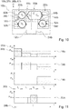
- Fig. 10 shows a further hob 38b with a cooking appliance device 10b with an exemplary fifth induction target arrangement.
- the first installation area 48b has five first inductors 20b.
- the second installation area 50b has five second inductors 22b.
- the inductors 20b, 22b each have an essentially rectangular contour.
- the inductors 20b, 22b occupied by the cookware 44b, 60b, 62b, 64b can be activated by the control unit 12b.
- the control unit 12b defines the one or more inductors 20b, 22b occupied by the cookware 44b, 60b, 62b, 64b together with the respective cookware 44b, 60b, 62b, 64b as an induction target. Overall, the control unit 12b defines a common induction target 14b and three dedicated induction targets 16b, 32b, 52b.
- the first and second dedicated induction targets 16b, 34b each have two first inductors 20b and a first or second cookware 60b, 62b placed over the respective inductors 20b.
- the dedicated induction target 52b has two second inductors 22b and a third cookware 64b placed over the inductors 22b.
- the control unit 12b defines a common induction target 14b.
- the common induction target 14b has a first inductor 20b and three second inductors 22b and a cookware 44b placed over the inductors 22b, 22b.
- the first dedicated induction target 16b and the second dedicated induction target 34b are assigned to the first installation area 48b.
- the third dedicated induction target 52b is assigned to the second installation area 50b.
- the control unit 12b supplies the first and second dedicated induction target 16b, 34b and the third dedicated induction target 52b from different energy sources.
- the first and second dedicated induction targets 16b, 34b can couple with each other while operating and produce coupling noises.
- control unit 12b selects suitable control options from the catalog of control options.
- Fig. 11 shows an exemplary diagram of an activation sequence of the one common induction target 14b and the three dedicated induction targets 16b, 34b, 52b of the fifth induction target arrangement.
- the control unit 12b divides the period 28b into four time sub-areas 30b t 1 , t 2 , t 3 , t 4 .
- the control unit 12b operates the common induction target 14b during the fourth partial time range 30b t 4 .
- the control unit 12b deactivates the common induction target 14b during the first, second and third partial time periods 30b t 1 , t 2 , t 3 .
- the control unit 12b operates the common induction target 14b during the fourth partial time range 30b t 4 together with the first and second dedicated induction targets 16b, 34b with the same heating frequency.
- the control unit 12b operates the dedicated induction targets 16b, 34b, 52b simultaneously under the condition of the flicker standard and while avoiding coupling noises between the first and second dedicated induction targets 16b, 34b a selection from the catalog of control options.
- the common induction target 14b and the dedicated induction targets 16b, 34b, 52b each deliver an average power 36b P TC , P TA I , P TB I , P TD II .
- Fig. 12 shows a further hob 38c with a cooking appliance device 10c with an exemplary sixth induction target arrangement.
- the control unit 12c defines induction targets 14c, 16c, 34c, 52c, 54c based on cooking utensils 44c, 60c, 62c, 64c, 66c set up on the base plate 42c.
- the induction targets 14c, 16c, 34c, 52c, 54c each have an inductor 20c, 22c, 70c, 72c, 74c and a cookware 44c, 60c, 62c, 64c, 66c placed over the respective inductor 20c, 22c, 70c, 72c, 74c on.
- the inductors 20c, 22c, 70c, 72c, 74c each have different diameters.
- the control unit 12c supplies the inductors 20c, 70c with electrical power from the first energy source.
- the first and second dedicated induction targets 16c, 34c are assigned to the first installation area 48c.
- the control unit 12c supplies the first and second dedicated induction target 16c, 34c from the first energy source.
- the control unit 12c supplies the inductors 22c, 74c with electrical power from the second energy source.
- the third and fourth dedicated induction targets 52c, 54c are assigned to the second installation area 50c.
- the control unit 12c supplies the third and fourth dedicated induction target 52c, 54c from the second energy source.
- the control unit 12c supplies the inductor 72c with electrical power from the first and second energy sources.
- the control unit 12c simultaneously supplies the inductor 72c with the same heating frequency from the first and second energy sources.
- the first and second dedicated induction targets 16c, 34c can couple to each other while operating and produce coupling noises.
- the third and fourth dedicated induction targets 52c, 54c can couple with each other while operating and produce coupling noises.
- control unit 12c selects suitable control options from the catalog of control options.
- Fig. 13 shows an exemplary diagram of an activation sequence of the one common induction target 14c and the four dedicated induction targets 16c, 34c, 52c, 54c of the sixth induction target arrangement
- the control unit 12c divides the period 28c into five time sub-areas 30c t 1 , t 2 , t 3 , t 4 , t 5 .
- the control unit 12c operates the common induction target 14c during the fifth partial time range 30c t 5 .
- the control unit 12c deactivates the common induction target 14c during the first, second, third and fourth partial time ranges 30c t 1 , t 2 , t 3 , t 4 .
- the control unit 12c operates the common, the second and third dedicated induction targets 14c, 34c, 52c simultaneously in the fifth time sub-range 30c t 5, the control unit 12c operating the dedicated induction targets 34c, 52c with the same heating frequency and the common induction target 14c with a heating frequency, which differ by at least 17 kHz.
- the control unit 12c operates the dedicated induction targets 16c, 34c, 52c, 54c simultaneously under the condition of the flicker standard and while avoiding coupling noises between the first and second dedicated Induction target 16c, 34c and between the third and fourth dedicated Induction target 52c, 54c through a selection from the catalog of control options.
- the common induction target 14c and the dedicated induction targets 16c, 34c, 52c, 54c each deliver an average power 36c P TC , P TA I , P TB I , P TD II , P TE II .
Landscapes
- Physics & Mathematics (AREA)
- Electromagnetism (AREA)
- Induction Heating Cooking Devices (AREA)
- Cookers (AREA)
Applications Claiming Priority (1)
| Application Number | Priority Date | Filing Date | Title |
|---|---|---|---|
| ES201831005A ES2754793A1 (es) | 2018-10-17 | 2018-10-17 | Dispositivo de Aparato de Cocción |
Publications (2)
| Publication Number | Publication Date |
|---|---|
| EP3641497A1 true EP3641497A1 (fr) | 2020-04-22 |
| EP3641497B1 EP3641497B1 (fr) | 2023-08-02 |
Family
ID=67998355
Family Applications (1)
| Application Number | Title | Priority Date | Filing Date |
|---|---|---|---|
| EP19198688.4A Active EP3641497B1 (fr) | 2018-10-17 | 2019-09-20 | Dispositif formant appareil de cuisson |
Country Status (2)
| Country | Link |
|---|---|
| EP (1) | EP3641497B1 (fr) |
| ES (2) | ES2754793A1 (fr) |
Cited By (2)
| Publication number | Priority date | Publication date | Assignee | Title |
|---|---|---|---|---|
| WO2022048839A1 (fr) * | 2020-09-02 | 2022-03-10 | BSH Hausgeräte GmbH | Dispositif de table de cuisson et procédé de fonctionnement d'un dispositif de table de cuisson |
| US20230189405A1 (en) * | 2021-12-10 | 2023-06-15 | Sabaf S.P.A. | Induction Cooktop and Method for Controlling an Induction Cooktop |
Citations (8)
| Publication number | Priority date | Publication date | Assignee | Title |
|---|---|---|---|---|
| EP1951003A1 (fr) | 2007-01-23 | 2008-07-30 | Whirlpool Corporation | Procédé de commande d'induction d'une plaque de cuisson et d'induction d'une plaque de cuisson adaptée à un tel procédé |
| WO2010069883A1 (fr) * | 2008-12-19 | 2010-06-24 | BSH Bosch und Siemens Hausgeräte GmbH | Plaque de cuisson à induction et procédé d'utilisation d'une plaque de cuisson à induction |
| US7910865B2 (en) | 2005-05-04 | 2011-03-22 | E.G.O. Elektro-Geraetebau Gmbh | Method and arrangement for supplying power to several induction coils in an induction apparatus |
| EP2306784A1 (fr) * | 2009-10-05 | 2011-04-06 | Whirlpool Corporation | Procédé de fourniture de puissance à des zones de cuisson par induction d'une plaque de cuisson par induction dotée d'une pluralité de convertisseurs de puissance, et plaque de cuisson par induction utilisant ledit procédé |
| EP2914059A1 (fr) * | 2012-10-24 | 2015-09-02 | Panasonic Intellectual Property Management Co., Ltd. | Dispositif de chauffage à induction |
| EP3001773A1 (fr) * | 2014-09-24 | 2016-03-30 | BSH Hausgeräte GmbH | Dispositif d'appareil de cuisson et procede destine au fonctionnement d'un dispositif d'appareil de cuisson |
| EP3282815A1 (fr) * | 2016-08-08 | 2018-02-14 | Electrolux Appliances Aktiebolag | Procédé de commande d'une plaque de cuisson à induction |
| EP3291642A1 (fr) * | 2016-09-02 | 2018-03-07 | Electrolux Appliances Aktiebolag | Plaque de cuisson et procédé de commande d'une zone de cuisson |
Family Cites Families (1)
| Publication number | Priority date | Publication date | Assignee | Title |
|---|---|---|---|---|
| ES2353890B1 (es) * | 2008-12-19 | 2012-01-26 | Bsh Electrodomesticos España, S.A. | Campo de cocción con al menos tres zonas de calentamiento. |
-
2018
- 2018-10-17 ES ES201831005A patent/ES2754793A1/es not_active Withdrawn
-
2019
- 2019-09-20 ES ES19198688T patent/ES2956085T3/es active Active
- 2019-09-20 EP EP19198688.4A patent/EP3641497B1/fr active Active
Patent Citations (8)
| Publication number | Priority date | Publication date | Assignee | Title |
|---|---|---|---|---|
| US7910865B2 (en) | 2005-05-04 | 2011-03-22 | E.G.O. Elektro-Geraetebau Gmbh | Method and arrangement for supplying power to several induction coils in an induction apparatus |
| EP1951003A1 (fr) | 2007-01-23 | 2008-07-30 | Whirlpool Corporation | Procédé de commande d'induction d'une plaque de cuisson et d'induction d'une plaque de cuisson adaptée à un tel procédé |
| WO2010069883A1 (fr) * | 2008-12-19 | 2010-06-24 | BSH Bosch und Siemens Hausgeräte GmbH | Plaque de cuisson à induction et procédé d'utilisation d'une plaque de cuisson à induction |
| EP2306784A1 (fr) * | 2009-10-05 | 2011-04-06 | Whirlpool Corporation | Procédé de fourniture de puissance à des zones de cuisson par induction d'une plaque de cuisson par induction dotée d'une pluralité de convertisseurs de puissance, et plaque de cuisson par induction utilisant ledit procédé |
| EP2914059A1 (fr) * | 2012-10-24 | 2015-09-02 | Panasonic Intellectual Property Management Co., Ltd. | Dispositif de chauffage à induction |
| EP3001773A1 (fr) * | 2014-09-24 | 2016-03-30 | BSH Hausgeräte GmbH | Dispositif d'appareil de cuisson et procede destine au fonctionnement d'un dispositif d'appareil de cuisson |
| EP3282815A1 (fr) * | 2016-08-08 | 2018-02-14 | Electrolux Appliances Aktiebolag | Procédé de commande d'une plaque de cuisson à induction |
| EP3291642A1 (fr) * | 2016-09-02 | 2018-03-07 | Electrolux Appliances Aktiebolag | Plaque de cuisson et procédé de commande d'une zone de cuisson |
Cited By (2)
| Publication number | Priority date | Publication date | Assignee | Title |
|---|---|---|---|---|
| WO2022048839A1 (fr) * | 2020-09-02 | 2022-03-10 | BSH Hausgeräte GmbH | Dispositif de table de cuisson et procédé de fonctionnement d'un dispositif de table de cuisson |
| US20230189405A1 (en) * | 2021-12-10 | 2023-06-15 | Sabaf S.P.A. | Induction Cooktop and Method for Controlling an Induction Cooktop |
Also Published As
| Publication number | Publication date |
|---|---|
| ES2754793A1 (es) | 2020-04-20 |
| ES2956085T3 (es) | 2023-12-13 |
| EP3641497B1 (fr) | 2023-08-02 |
Similar Documents
| Publication | Publication Date | Title |
|---|---|---|
| EP2236004B1 (fr) | Plaque de cuisson à induction munie d'une pluralité d'éléments chauffants à induction | |
| EP2342943B1 (fr) | Plaque de cuisson et procédé permettant de faire fonctionner une plaque de cuisson | |
| EP1683257B1 (fr) | Procede d'evitement ou reduction du bruit dans un convertisseur avec beaucoup de sorties simultanément actionnées | |
| EP2177076B1 (fr) | Plaque de cuisson comportant une multitude d'éléments chauffants et procédé d'exploitation de la plaque de cuisson | |
| EP2586271B1 (fr) | Ensemble table de cuisson | |
| EP2506663A1 (fr) | Dispositif d'appareil de cuisson | |
| WO2018116063A1 (fr) | Dispositif formant appareil de cuisson et procédé de fonctionnement d'un dispositif formant appareil de cuisson | |
| EP2469970A2 (fr) | Dispositif d'appareil de cuisson | |
| EP2506665B1 (fr) | Dispositif d'appareil de cuisson | |
| EP3641497B1 (fr) | Dispositif formant appareil de cuisson | |
| EP2506666B1 (fr) | Dispositif d'appareil de cuisson | |
| EP3641494B1 (fr) | Dispositif formant appareil de cuisson | |
| EP3967108A1 (fr) | Ensemble appareil de cuisson | |
| EP2469972B1 (fr) | Dispositif d'appareil de cuisson et procédé de contrôle d'un appareil de cuisson qui diminue d'une manière itérative une caractéristique flicker. | |
| EP2469971B1 (fr) | Dispositif d'appareil de cuisson | |
| EP4159003B1 (fr) | Appareil électroménager | |
| EP3664578B1 (fr) | Dispositif formant appareil de cuisson | |
| EP4581905A1 (fr) | Système de transmission d'énergie par induction | |
| EP2506664B1 (fr) | Dispositif d'appareil de cuisson | |
| DE102019215954A1 (de) | Gargerätevorrichtung | |
| EP3484242B1 (fr) | Dispositif formant appareil de cuisson inductif | |
| DE102012211399A1 (de) | Hausgerätevorrichtung | |
| EP3967107A1 (fr) | Ensemble appareil de cuisson | |
| EP2945461B1 (fr) | Dispositif d'appareil de cuisson | |
| EP4581902A1 (fr) | Appareil de cuisson |
Legal Events
| Date | Code | Title | Description |
|---|---|---|---|
| PUAI | Public reference made under article 153(3) epc to a published international application that has entered the european phase |
Free format text: ORIGINAL CODE: 0009012 |
|
| STAA | Information on the status of an ep patent application or granted ep patent |
Free format text: STATUS: THE APPLICATION HAS BEEN PUBLISHED |
|
| AK | Designated contracting states |
Kind code of ref document: A1 Designated state(s): AL AT BE BG CH CY CZ DE DK EE ES FI FR GB GR HR HU IE IS IT LI LT LU LV MC MK MT NL NO PL PT RO RS SE SI SK SM TR |
|
| AX | Request for extension of the european patent |
Extension state: BA ME |
|
| STAA | Information on the status of an ep patent application or granted ep patent |
Free format text: STATUS: REQUEST FOR EXAMINATION WAS MADE |
|
| 17P | Request for examination filed |
Effective date: 20201022 |
|
| RBV | Designated contracting states (corrected) |
Designated state(s): AL AT BE BG CH CY CZ DE DK EE ES FI FR GB GR HR HU IE IS IT LI LT LU LV MC MK MT NL NO PL PT RO RS SE SI SK SM TR |
|
| STAA | Information on the status of an ep patent application or granted ep patent |
Free format text: STATUS: EXAMINATION IS IN PROGRESS |
|
| 17Q | First examination report despatched |
Effective date: 20220915 |
|
| GRAP | Despatch of communication of intention to grant a patent |
Free format text: ORIGINAL CODE: EPIDOSNIGR1 |
|
| STAA | Information on the status of an ep patent application or granted ep patent |
Free format text: STATUS: GRANT OF PATENT IS INTENDED |
|
| INTG | Intention to grant announced |
Effective date: 20230328 |
|
| GRAS | Grant fee paid |
Free format text: ORIGINAL CODE: EPIDOSNIGR3 |
|
| GRAA | (expected) grant |
Free format text: ORIGINAL CODE: 0009210 |
|
| STAA | Information on the status of an ep patent application or granted ep patent |
Free format text: STATUS: THE PATENT HAS BEEN GRANTED |
|
| AK | Designated contracting states |
Kind code of ref document: B1 Designated state(s): AL AT BE BG CH CY CZ DE DK EE ES FI FR GB GR HR HU IE IS IT LI LT LU LV MC MK MT NL NO PL PT RO RS SE SI SK SM TR |
|
| REG | Reference to a national code |
Ref country code: GB Ref legal event code: FG4D Free format text: NOT ENGLISH |
|
| REG | Reference to a national code |
Ref country code: CH Ref legal event code: EP |
|
| REG | Reference to a national code |
Ref country code: DE Ref legal event code: R096 Ref document number: 502019008731 Country of ref document: DE |
|
| REG | Reference to a national code |
Ref country code: IE Ref legal event code: FG4D Free format text: LANGUAGE OF EP DOCUMENT: GERMAN |
|
| REG | Reference to a national code |
Ref country code: NL Ref legal event code: FP |
|
| REG | Reference to a national code |
Ref country code: LT Ref legal event code: MG9D |
|
| REG | Reference to a national code |
Ref country code: ES Ref legal event code: FG2A Ref document number: 2956085 Country of ref document: ES Kind code of ref document: T3 Effective date: 20231213 |
|
| PG25 | Lapsed in a contracting state [announced via postgrant information from national office to epo] |
Ref country code: GR Free format text: LAPSE BECAUSE OF FAILURE TO SUBMIT A TRANSLATION OF THE DESCRIPTION OR TO PAY THE FEE WITHIN THE PRESCRIBED TIME-LIMIT Effective date: 20231103 |
|
| PG25 | Lapsed in a contracting state [announced via postgrant information from national office to epo] |
Ref country code: IS Free format text: LAPSE BECAUSE OF FAILURE TO SUBMIT A TRANSLATION OF THE DESCRIPTION OR TO PAY THE FEE WITHIN THE PRESCRIBED TIME-LIMIT Effective date: 20231202 |
|
| PG25 | Lapsed in a contracting state [announced via postgrant information from national office to epo] |
Ref country code: SE Free format text: LAPSE BECAUSE OF FAILURE TO SUBMIT A TRANSLATION OF THE DESCRIPTION OR TO PAY THE FEE WITHIN THE PRESCRIBED TIME-LIMIT Effective date: 20230802 Ref country code: RS Free format text: LAPSE BECAUSE OF FAILURE TO SUBMIT A TRANSLATION OF THE DESCRIPTION OR TO PAY THE FEE WITHIN THE PRESCRIBED TIME-LIMIT Effective date: 20230802 Ref country code: PT Free format text: LAPSE BECAUSE OF FAILURE TO SUBMIT A TRANSLATION OF THE DESCRIPTION OR TO PAY THE FEE WITHIN THE PRESCRIBED TIME-LIMIT Effective date: 20231204 Ref country code: NO Free format text: LAPSE BECAUSE OF FAILURE TO SUBMIT A TRANSLATION OF THE DESCRIPTION OR TO PAY THE FEE WITHIN THE PRESCRIBED TIME-LIMIT Effective date: 20231102 Ref country code: LV Free format text: LAPSE BECAUSE OF FAILURE TO SUBMIT A TRANSLATION OF THE DESCRIPTION OR TO PAY THE FEE WITHIN THE PRESCRIBED TIME-LIMIT Effective date: 20230802 Ref country code: LT Free format text: LAPSE BECAUSE OF FAILURE TO SUBMIT A TRANSLATION OF THE DESCRIPTION OR TO PAY THE FEE WITHIN THE PRESCRIBED TIME-LIMIT Effective date: 20230802 Ref country code: IS Free format text: LAPSE BECAUSE OF FAILURE TO SUBMIT A TRANSLATION OF THE DESCRIPTION OR TO PAY THE FEE WITHIN THE PRESCRIBED TIME-LIMIT Effective date: 20231202 Ref country code: HR Free format text: LAPSE BECAUSE OF FAILURE TO SUBMIT A TRANSLATION OF THE DESCRIPTION OR TO PAY THE FEE WITHIN THE PRESCRIBED TIME-LIMIT Effective date: 20230802 Ref country code: GR Free format text: LAPSE BECAUSE OF FAILURE TO SUBMIT A TRANSLATION OF THE DESCRIPTION OR TO PAY THE FEE WITHIN THE PRESCRIBED TIME-LIMIT Effective date: 20231103 Ref country code: FI Free format text: LAPSE BECAUSE OF FAILURE TO SUBMIT A TRANSLATION OF THE DESCRIPTION OR TO PAY THE FEE WITHIN THE PRESCRIBED TIME-LIMIT Effective date: 20230802 |
|
| PG25 | Lapsed in a contracting state [announced via postgrant information from national office to epo] |
Ref country code: PL Free format text: LAPSE BECAUSE OF FAILURE TO SUBMIT A TRANSLATION OF THE DESCRIPTION OR TO PAY THE FEE WITHIN THE PRESCRIBED TIME-LIMIT Effective date: 20230802 |
|
| PG25 | Lapsed in a contracting state [announced via postgrant information from national office to epo] |
Ref country code: SM Free format text: LAPSE BECAUSE OF FAILURE TO SUBMIT A TRANSLATION OF THE DESCRIPTION OR TO PAY THE FEE WITHIN THE PRESCRIBED TIME-LIMIT Effective date: 20230802 Ref country code: RO Free format text: LAPSE BECAUSE OF FAILURE TO SUBMIT A TRANSLATION OF THE DESCRIPTION OR TO PAY THE FEE WITHIN THE PRESCRIBED TIME-LIMIT Effective date: 20230802 Ref country code: EE Free format text: LAPSE BECAUSE OF FAILURE TO SUBMIT A TRANSLATION OF THE DESCRIPTION OR TO PAY THE FEE WITHIN THE PRESCRIBED TIME-LIMIT Effective date: 20230802 Ref country code: DK Free format text: LAPSE BECAUSE OF FAILURE TO SUBMIT A TRANSLATION OF THE DESCRIPTION OR TO PAY THE FEE WITHIN THE PRESCRIBED TIME-LIMIT Effective date: 20230802 Ref country code: CZ Free format text: LAPSE BECAUSE OF FAILURE TO SUBMIT A TRANSLATION OF THE DESCRIPTION OR TO PAY THE FEE WITHIN THE PRESCRIBED TIME-LIMIT Effective date: 20230802 Ref country code: SK Free format text: LAPSE BECAUSE OF FAILURE TO SUBMIT A TRANSLATION OF THE DESCRIPTION OR TO PAY THE FEE WITHIN THE PRESCRIBED TIME-LIMIT Effective date: 20230802 |
|
| REG | Reference to a national code |
Ref country code: CH Ref legal event code: PL |
|
| REG | Reference to a national code |
Ref country code: DE Ref legal event code: R097 Ref document number: 502019008731 Country of ref document: DE |
|
| PG25 | Lapsed in a contracting state [announced via postgrant information from national office to epo] |
Ref country code: LU Free format text: LAPSE BECAUSE OF NON-PAYMENT OF DUE FEES Effective date: 20230920 |
|
| REG | Reference to a national code |
Ref country code: BE Ref legal event code: MM Effective date: 20230930 |
|
| PG25 | Lapsed in a contracting state [announced via postgrant information from national office to epo] |
Ref country code: LU Free format text: LAPSE BECAUSE OF NON-PAYMENT OF DUE FEES Effective date: 20230920 Ref country code: IT Free format text: LAPSE BECAUSE OF FAILURE TO SUBMIT A TRANSLATION OF THE DESCRIPTION OR TO PAY THE FEE WITHIN THE PRESCRIBED TIME-LIMIT Effective date: 20230802 Ref country code: MC Free format text: LAPSE BECAUSE OF FAILURE TO SUBMIT A TRANSLATION OF THE DESCRIPTION OR TO PAY THE FEE WITHIN THE PRESCRIBED TIME-LIMIT Effective date: 20230802 |
|
| PLBE | No opposition filed within time limit |
Free format text: ORIGINAL CODE: 0009261 |
|
| STAA | Information on the status of an ep patent application or granted ep patent |
Free format text: STATUS: NO OPPOSITION FILED WITHIN TIME LIMIT |
|
| REG | Reference to a national code |
Ref country code: IE Ref legal event code: MM4A |
|
| PG25 | Lapsed in a contracting state [announced via postgrant information from national office to epo] |
Ref country code: IE Free format text: LAPSE BECAUSE OF NON-PAYMENT OF DUE FEES Effective date: 20230920 |
|
| 26N | No opposition filed |
Effective date: 20240503 |
|
| PG25 | Lapsed in a contracting state [announced via postgrant information from national office to epo] |
Ref country code: CH Free format text: LAPSE BECAUSE OF NON-PAYMENT OF DUE FEES Effective date: 20230930 |
|
| PG25 | Lapsed in a contracting state [announced via postgrant information from national office to epo] |
Ref country code: IE Free format text: LAPSE BECAUSE OF NON-PAYMENT OF DUE FEES Effective date: 20230920 Ref country code: CH Free format text: LAPSE BECAUSE OF NON-PAYMENT OF DUE FEES Effective date: 20230930 Ref country code: SI Free format text: LAPSE BECAUSE OF FAILURE TO SUBMIT A TRANSLATION OF THE DESCRIPTION OR TO PAY THE FEE WITHIN THE PRESCRIBED TIME-LIMIT Effective date: 20230802 |
|
| PG25 | Lapsed in a contracting state [announced via postgrant information from national office to epo] |
Ref country code: BE Free format text: LAPSE BECAUSE OF NON-PAYMENT OF DUE FEES Effective date: 20230930 |
|
| PG25 | Lapsed in a contracting state [announced via postgrant information from national office to epo] |
Ref country code: BG Free format text: LAPSE BECAUSE OF FAILURE TO SUBMIT A TRANSLATION OF THE DESCRIPTION OR TO PAY THE FEE WITHIN THE PRESCRIBED TIME-LIMIT Effective date: 20230802 |
|
| PG25 | Lapsed in a contracting state [announced via postgrant information from national office to epo] |
Ref country code: BG Free format text: LAPSE BECAUSE OF FAILURE TO SUBMIT A TRANSLATION OF THE DESCRIPTION OR TO PAY THE FEE WITHIN THE PRESCRIBED TIME-LIMIT Effective date: 20230802 |
|
| PG25 | Lapsed in a contracting state [announced via postgrant information from national office to epo] |
Ref country code: CY Free format text: LAPSE BECAUSE OF FAILURE TO SUBMIT A TRANSLATION OF THE DESCRIPTION OR TO PAY THE FEE WITHIN THE PRESCRIBED TIME-LIMIT; INVALID AB INITIO Effective date: 20190920 |
|
| PG25 | Lapsed in a contracting state [announced via postgrant information from national office to epo] |
Ref country code: HU Free format text: LAPSE BECAUSE OF FAILURE TO SUBMIT A TRANSLATION OF THE DESCRIPTION OR TO PAY THE FEE WITHIN THE PRESCRIBED TIME-LIMIT; INVALID AB INITIO Effective date: 20190920 |
|
| PGFP | Annual fee paid to national office [announced via postgrant information from national office to epo] |
Ref country code: DE Payment date: 20250930 Year of fee payment: 7 |
|
| PGFP | Annual fee paid to national office [announced via postgrant information from national office to epo] |
Ref country code: NL Payment date: 20250922 Year of fee payment: 7 |
|
| PGFP | Annual fee paid to national office [announced via postgrant information from national office to epo] |
Ref country code: GB Payment date: 20250923 Year of fee payment: 7 |
|
| PGFP | Annual fee paid to national office [announced via postgrant information from national office to epo] |
Ref country code: FR Payment date: 20250922 Year of fee payment: 7 |
|
| REG | Reference to a national code |
Ref country code: AT Ref legal event code: MM01 Ref document number: 1596311 Country of ref document: AT Kind code of ref document: T Effective date: 20240920 |
|
| PG25 | Lapsed in a contracting state [announced via postgrant information from national office to epo] |
Ref country code: TR Free format text: LAPSE BECAUSE OF FAILURE TO SUBMIT A TRANSLATION OF THE DESCRIPTION OR TO PAY THE FEE WITHIN THE PRESCRIBED TIME-LIMIT Effective date: 20230802 |
|
| PG25 | Lapsed in a contracting state [announced via postgrant information from national office to epo] |
Ref country code: AT Free format text: LAPSE BECAUSE OF NON-PAYMENT OF DUE FEES Effective date: 20240920 |
|
| PGFP | Annual fee paid to national office [announced via postgrant information from national office to epo] |
Ref country code: ES Payment date: 20251020 Year of fee payment: 7 |
|
| PGFP | Annual fee paid to national office [announced via postgrant information from national office to epo] |
Ref country code: AT Payment date: 20260410 Year of fee payment: 5 |