EP3642007B1 - Appareil et procede de formation de sachets hydrosolubles - Google Patents
Appareil et procede de formation de sachets hydrosolubles Download PDFInfo
- Publication number
- EP3642007B1 EP3642007B1 EP18740008.0A EP18740008A EP3642007B1 EP 3642007 B1 EP3642007 B1 EP 3642007B1 EP 18740008 A EP18740008 A EP 18740008A EP 3642007 B1 EP3642007 B1 EP 3642007B1
- Authority
- EP
- European Patent Office
- Prior art keywords
- mold
- face
- web
- trailing
- leading
- Prior art date
- Legal status (The legal status is an assumption and is not a legal conclusion. Google has not performed a legal analysis and makes no representation as to the accuracy of the status listed.)
- Active
Links
Images




Classifications
-
- B—PERFORMING OPERATIONS; TRANSPORTING
- B65—CONVEYING; PACKING; STORING; HANDLING THIN OR FILAMENTARY MATERIAL
- B65B—MACHINES, APPARATUS OR DEVICES FOR, OR METHODS OF, PACKAGING ARTICLES OR MATERIALS; UNPACKING
- B65B47/00—Apparatus or devices for forming pockets or receptacles in or from sheets, blanks, or webs, comprising essentially a die into which the material is pressed or a folding die through which the material is moved
- B65B47/08—Apparatus or devices for forming pockets or receptacles in or from sheets, blanks, or webs, comprising essentially a die into which the material is pressed or a folding die through which the material is moved by application of fluid pressure
- B65B47/10—Apparatus or devices for forming pockets or receptacles in or from sheets, blanks, or webs, comprising essentially a die into which the material is pressed or a folding die through which the material is moved by application of fluid pressure by vacuum
-
- B—PERFORMING OPERATIONS; TRANSPORTING
- B65—CONVEYING; PACKING; STORING; HANDLING THIN OR FILAMENTARY MATERIAL
- B65B—MACHINES, APPARATUS OR DEVICES FOR, OR METHODS OF, PACKAGING ARTICLES OR MATERIALS; UNPACKING
- B65B1/00—Packaging fluent solid material, e.g. powders, granular or loose fibrous material, loose masses of small articles, in individual containers or receptacles, e.g. bags, sacks, boxes, cartons, cans, or jars
- B65B1/04—Methods of, or means for, filling the material into the containers or receptacles
- B65B1/16—Methods of, or means for, filling the material into the containers or receptacles by pneumatic means, e.g. by suction
-
- B—PERFORMING OPERATIONS; TRANSPORTING
- B29—WORKING OF PLASTICS; WORKING OF SUBSTANCES IN A PLASTIC STATE IN GENERAL
- B29C—SHAPING OR JOINING OF PLASTICS; SHAPING OF MATERIAL IN A PLASTIC STATE, NOT OTHERWISE PROVIDED FOR; AFTER-TREATMENT OF THE SHAPED PRODUCTS, e.g. REPAIRING
- B29C51/00—Shaping by thermoforming, i.e. shaping sheets or sheet like preforms after heating, e.g. shaping sheets in matched moulds or by deep-drawing; Apparatus therefor
- B29C51/10—Forming by pressure difference, e.g. vacuum
-
- B—PERFORMING OPERATIONS; TRANSPORTING
- B29—WORKING OF PLASTICS; WORKING OF SUBSTANCES IN A PLASTIC STATE IN GENERAL
- B29C—SHAPING OR JOINING OF PLASTICS; SHAPING OF MATERIAL IN A PLASTIC STATE, NOT OTHERWISE PROVIDED FOR; AFTER-TREATMENT OF THE SHAPED PRODUCTS, e.g. REPAIRING
- B29C51/00—Shaping by thermoforming, i.e. shaping sheets or sheet like preforms after heating, e.g. shaping sheets in matched moulds or by deep-drawing; Apparatus therefor
- B29C51/18—Thermoforming apparatus
- B29C51/20—Thermoforming apparatus having movable moulds or mould parts
- B29C51/24—Thermoforming apparatus having movable moulds or mould parts mounted on movable endless supports
-
- B—PERFORMING OPERATIONS; TRANSPORTING
- B29—WORKING OF PLASTICS; WORKING OF SUBSTANCES IN A PLASTIC STATE IN GENERAL
- B29C—SHAPING OR JOINING OF PLASTICS; SHAPING OF MATERIAL IN A PLASTIC STATE, NOT OTHERWISE PROVIDED FOR; AFTER-TREATMENT OF THE SHAPED PRODUCTS, e.g. REPAIRING
- B29C51/00—Shaping by thermoforming, i.e. shaping sheets or sheet like preforms after heating, e.g. shaping sheets in matched moulds or by deep-drawing; Apparatus therefor
- B29C51/26—Component parts, details or accessories; Auxiliary operations
- B29C51/261—Handling means, e.g. transfer means, feeding means
- B29C51/262—Clamping means for the sheets, e.g. clamping frames
-
- B—PERFORMING OPERATIONS; TRANSPORTING
- B29—WORKING OF PLASTICS; WORKING OF SUBSTANCES IN A PLASTIC STATE IN GENERAL
- B29C—SHAPING OR JOINING OF PLASTICS; SHAPING OF MATERIAL IN A PLASTIC STATE, NOT OTHERWISE PROVIDED FOR; AFTER-TREATMENT OF THE SHAPED PRODUCTS, e.g. REPAIRING
- B29C51/00—Shaping by thermoforming, i.e. shaping sheets or sheet like preforms after heating, e.g. shaping sheets in matched moulds or by deep-drawing; Apparatus therefor
- B29C51/26—Component parts, details or accessories; Auxiliary operations
- B29C51/30—Moulds
- B29C51/36—Moulds specially adapted for vacuum forming, Manufacture thereof
-
- B—PERFORMING OPERATIONS; TRANSPORTING
- B65—CONVEYING; PACKING; STORING; HANDLING THIN OR FILAMENTARY MATERIAL
- B65B—MACHINES, APPARATUS OR DEVICES FOR, OR METHODS OF, PACKAGING ARTICLES OR MATERIALS; UNPACKING
- B65B39/00—Nozzles, funnels or guides for introducing articles or materials into containers or wrappers
- B65B39/007—Guides or funnels for introducing articles into containers or wrappers
-
- B—PERFORMING OPERATIONS; TRANSPORTING
- B65—CONVEYING; PACKING; STORING; HANDLING THIN OR FILAMENTARY MATERIAL
- B65B—MACHINES, APPARATUS OR DEVICES FOR, OR METHODS OF, PACKAGING ARTICLES OR MATERIALS; UNPACKING
- B65B51/00—Devices for, or methods of, sealing or securing package folds or closures; Devices for gathering or twisting wrappers, or necks of bags
- B65B51/10—Applying or generating heat or pressure or combinations thereof
- B65B51/18—Applying or generating heat or pressure or combinations thereof by endless bands or chains
-
- B—PERFORMING OPERATIONS; TRANSPORTING
- B65—CONVEYING; PACKING; STORING; HANDLING THIN OR FILAMENTARY MATERIAL
- B65B—MACHINES, APPARATUS OR DEVICES FOR, OR METHODS OF, PACKAGING ARTICLES OR MATERIALS; UNPACKING
- B65B9/00—Enclosing successive articles, or quantities of material, e.g. liquids or semiliquids, in flat, folded, or tubular webs of flexible sheet material; Subdividing filled flexible tubes to form packages
- B65B9/02—Enclosing successive articles, or quantities of material between opposed webs
- B65B9/04—Enclosing successive articles, or quantities of material between opposed webs one or both webs being formed with pockets for the reception of the articles, or of the quantities of material
- B65B9/042—Enclosing successive articles, or quantities of material between opposed webs one or both webs being formed with pockets for the reception of the articles, or of the quantities of material for fluent material
-
- C—CHEMISTRY; METALLURGY
- C11—ANIMAL OR VEGETABLE OILS, FATS, FATTY SUBSTANCES OR WAXES; FATTY ACIDS THEREFROM; DETERGENTS; CANDLES
- C11D—DETERGENT COMPOSITIONS; USE OF SINGLE SUBSTANCES AS DETERGENTS; SOAP OR SOAP-MAKING; RESIN SOAPS; RECOVERY OF GLYCEROL
- C11D17/00—Detergent materials or soaps characterised by their shape or physical properties
- C11D17/04—Detergent materials or soaps characterised by their shape or physical properties combined with or containing other objects
- C11D17/041—Compositions releasably affixed on a substrate or incorporated into a dispensing means
- C11D17/042—Water soluble or water disintegrable containers or substrates containing cleaning compositions or additives for cleaning compositions
-
- B—PERFORMING OPERATIONS; TRANSPORTING
- B29—WORKING OF PLASTICS; WORKING OF SUBSTANCES IN A PLASTIC STATE IN GENERAL
- B29C—SHAPING OR JOINING OF PLASTICS; SHAPING OF MATERIAL IN A PLASTIC STATE, NOT OTHERWISE PROVIDED FOR; AFTER-TREATMENT OF THE SHAPED PRODUCTS, e.g. REPAIRING
- B29C2791/00—Shaping characteristics in general
- B29C2791/004—Shaping under special conditions
- B29C2791/006—Using vacuum
-
- B—PERFORMING OPERATIONS; TRANSPORTING
- B29—WORKING OF PLASTICS; WORKING OF SUBSTANCES IN A PLASTIC STATE IN GENERAL
- B29L—INDEXING SCHEME ASSOCIATED WITH SUBCLASS B29C, RELATING TO PARTICULAR ARTICLES
- B29L2031/00—Other particular articles
- B29L2031/712—Containers; Packaging elements or accessories, Packages
- B29L2031/7128—Bags, sacks, sachets
-
- B—PERFORMING OPERATIONS; TRANSPORTING
- B29—WORKING OF PLASTICS; WORKING OF SUBSTANCES IN A PLASTIC STATE IN GENERAL
- B29L—INDEXING SCHEME ASSOCIATED WITH SUBCLASS B29C, RELATING TO PARTICULAR ARTICLES
- B29L2031/00—Other particular articles
- B29L2031/712—Containers; Packaging elements or accessories, Packages
- B29L2031/7174—Capsules
-
- B—PERFORMING OPERATIONS; TRANSPORTING
- B65—CONVEYING; PACKING; STORING; HANDLING THIN OR FILAMENTARY MATERIAL
- B65B—MACHINES, APPARATUS OR DEVICES FOR, OR METHODS OF, PACKAGING ARTICLES OR MATERIALS; UNPACKING
- B65B1/00—Packaging fluent solid material, e.g. powders, granular or loose fibrous material, loose masses of small articles, in individual containers or receptacles, e.g. bags, sacks, boxes, cartons, cans, or jars
- B65B1/30—Devices or methods for controlling or determining the quantity or quality or the material fed or filled
- B65B1/48—Checking volume of filled material
-
- B—PERFORMING OPERATIONS; TRANSPORTING
- B65—CONVEYING; PACKING; STORING; HANDLING THIN OR FILAMENTARY MATERIAL
- B65B—MACHINES, APPARATUS OR DEVICES FOR, OR METHODS OF, PACKAGING ARTICLES OR MATERIALS; UNPACKING
- B65B39/00—Nozzles, funnels or guides for introducing articles or materials into containers or wrappers
- B65B2039/009—Multiple outlets
-
- B—PERFORMING OPERATIONS; TRANSPORTING
- B65—CONVEYING; PACKING; STORING; HANDLING THIN OR FILAMENTARY MATERIAL
- B65B—MACHINES, APPARATUS OR DEVICES FOR, OR METHODS OF, PACKAGING ARTICLES OR MATERIALS; UNPACKING
- B65B51/00—Devices for, or methods of, sealing or securing package folds or closures; Devices for gathering or twisting wrappers, or necks of bags
- B65B51/10—Applying or generating heat or pressure or combinations thereof
- B65B2051/105—Heat seal temperature control
-
- B—PERFORMING OPERATIONS; TRANSPORTING
- B65—CONVEYING; PACKING; STORING; HANDLING THIN OR FILAMENTARY MATERIAL
- B65B—MACHINES, APPARATUS OR DEVICES FOR, OR METHODS OF, PACKAGING ARTICLES OR MATERIALS; UNPACKING
- B65B2230/00—Aspects of the final package
- B65B2230/02—Containers having separate compartments isolated from one another
-
- B—PERFORMING OPERATIONS; TRANSPORTING
- B65—CONVEYING; PACKING; STORING; HANDLING THIN OR FILAMENTARY MATERIAL
- B65B—MACHINES, APPARATUS OR DEVICES FOR, OR METHODS OF, PACKAGING ARTICLES OR MATERIALS; UNPACKING
- B65B39/00—Nozzles, funnels or guides for introducing articles or materials into containers or wrappers
- B65B39/14—Nozzles, funnels or guides for introducing articles or materials into containers or wrappers movable with a moving container or wrapper during filling or depositing
-
- B—PERFORMING OPERATIONS; TRANSPORTING
- B65—CONVEYING; PACKING; STORING; HANDLING THIN OR FILAMENTARY MATERIAL
- B65B—MACHINES, APPARATUS OR DEVICES FOR, OR METHODS OF, PACKAGING ARTICLES OR MATERIALS; UNPACKING
- B65B47/00—Apparatus or devices for forming pockets or receptacles in or from sheets, blanks, or webs, comprising essentially a die into which the material is pressed or a folding die through which the material is moved
- B65B47/02—Apparatus or devices for forming pockets or receptacles in or from sheets, blanks, or webs, comprising essentially a die into which the material is pressed or a folding die through which the material is moved with means for heating the material prior to forming
Definitions
- Substrate treatment agent pouches are becoming the laundry and dish product form of choice for many consumers. Consumers enjoy being able to use the substrate treatment agent, which may be a detergent composition, without having to come into contact with the substrate treatment agent since some of these agents may have a slimy feel and may be difficult to rinse from their skin.
- Substrate treatment agent pouches may contain one or more of powder composition, liquid composition, and combinations thereof.
- a typical process used to form pouches containing a substrate treatment agent is to provide a bottom continuous web of water soluble film carried on a mold having one or more recesses and conforming the film to the recesses of the mold so that the web has a plurality of compartments.
- the compartments can be at least partially filled with liquid or powder substrate treatment agent.
- a second continuous web of water soluble film is placed over the first continuous web and the second continuous web is bonded to seal landings between the compartments in the first continuous web to form an array of pouches.
- the array of pouches may extend in one or more of the machine direction and or cross direction. Downstream of the forming and filling operations the array of pouches is cut in one or more of the machine direction and or cross direction to provide individual pouches.
- Multi-chamber pouches having two or more separate chambers are also gaining in popularity with consumers.
- Multi-chamber pouches help to solve the problems associated with formula components that are incompatible with one another when provided in a single mixture.
- Incompatible formula components can be placed in separate chambers and when the multi-chamber pouch is used, the formula components can be combined when components of the multi-chamber pouch dissolve.
- Multi-chamber pouches in which one chamber is superposed on and bonded to another chamber are practical because such pouches may be more physically stable than multi-chamber pouches in which the pouches are arranged in a side by side or concentric arrangement and have a smaller footprint compared to side by side arranged multi-chamber pouches.
- Multi-chamber superposed pouches are challenging to manufacture because at some point in the typical manufacturing process employed to make such pouches, one of the chambers must be turned upside-down and bonded to the other chamber or a portion of the web forming the other chamber. If the chamber being turned upside-down is formed on a cylindrical drum, there is only a short window at the apex of the cylindrical drum to both fill and close such chamber. The short window for filling and sealing on the apex of the cylindrical drum becomes the rate limiting step in the process of forming superposed pouches. If the rate of filling and sealing is simply increased, there is potential for splashing and dripping from the filling process, which can interfere with bonding the webs together to form the pouch.
- the time for bonding the webs together to form the pouch is decreased, which can result in a decrease in or lack of integrity of the bond between the webs. Further, if the cylindrical drum upon which one chamber is formed is used to bond such chamber to another chamber, there may be limited contact time between that drum and the bearing surface to form the bond.
- the belt may be formed of a flexible material having a plurality of recesses.
- the belt traverses two or more rollers as each recess transitions from a right-side-up position to an upside-down position and back to a right-side-up position.
- One problem with continuous belts is that the materials used to form such belts are prone to fatigue failure arising from the repetitive bending and straightening of the belt as it traverses the rollers.
- Forming belts are expensive to replace and the downtime required to replace such belts limits the productivity gains that can be obtained from employing such continuous belts.
- US5682733A , US2017088298A , EP1375351A and WO2013190517 relate to apparatus and processes for making a plurality of water-soluble pouches.
- An apparatus comprising: a plurality of forming molds (20), each said mold comprising: a leading edge (30) extending in a cross direction (CD); a trailing edge (40) extending in said cross direction; a mold face (50) extending from said leading edge to said trailing edge in a machine direction (MD) orthogonal to said cross direction; a plurality of first recesses (60) in said mold face positioned across said mold face in a said cross direction, each said first recess in fluid communication with a first vacuum duct (70); a leading face (80) extending from said leading edge in a direction away from said mold face; a trailing face (90) extending from said trailing edge in a direction away from said mold face; wherein at least a portion of said leading face is recessed relative to said mold face proximal said leading edge or at least a portion of said trailing face is recessed relative to said mold face proximal said trailing edge; wherein said plurality of forming molds is arranged leading edge to
- Figure 1 illustrates a plurality of forming molds 20 having a rectangular cross-section carrying a water soluble first web 250 traversing a roller 310.
- the web 250 is strained since the path that the first web 250 travels by, over, on, or around the roller 310 is longer than the path the forming mold 20 travels by, over, or around the roller.
- the tighter the turn by, over, around, or on the roller 310 the greater the strain on the first web 250.
- the thickness of the first web decreases. If the strain on the first web 250 is too high, the first web may be weakened, torn, or wrinkled.
- the magnitude of strain on the web 250 decreases with increasing diameter of the roller 310. Increasing the diameter of the roller 310 results in the apparatus taking up more space, which is inefficient. Further, even if the roller 310 is large, the web 250 is strained to some degree, which may weaken or deform the web 250.
- FIG. 2 An apparatus 10 for forming superposed water soluble pouches that can be operated at high speed is shown in Fig. 2 .
- the apparatus 10 shown in Fig. 2 can be referred to as a belt-above-belt apparatus.
- the top compartment or compartments are formed on one sub-apparatus and the bottom compartment or compartments are formed on another sub-apparatus.
- the top sub-apparatus for forming the top compartment or compartments can operate in the counterclockwise direction.
- the bottom sub-apparatus for forming the bottom compartment or compartments can operate in the clockwise direction.
- a water soluble first web 250 is fed to the apparatus 10.
- the first web 250 can be a water soluble film.
- the first web 250 may be provided from a parent roll of such material.
- the parent roll may have a cross-direction across which multiple lanes of water pouches 240 can be made.
- the water soluble first web 250 may be fed through a system of rollers and or tensioners onto the first mold belt 100.
- the first mold belt 100 can comprise a plurality of forming molds 20.
- the water soluble first web 250 is formed into recesses in the mold faces of the forming molds 20. Once the water soluble first web 250 is conformed to the first recess, the deformed portion of the water soluble first web 250 forms a first compartment.
- a first substrate treatment agent can be placed into the first compartment, for instance by a first nozzle 390.
- the first nozzle 390 may be engaged with a reciprocating shuttle that moves the nozzle back and forth in the machine direction MD.
- the reciprocating shuttle may be a variable speed shuttle to reduce the inertial forces associated with reciprocating movements. For instance, upon a change in direction, the acceleration may gradually increase until the desired velocity is obtained. In advance of the shuttle reversing direction, the deceleration may gradually increase until the shuttle stops and reverses direction.
- Movement of the shuttle may be provided with a reciprocating servo motor with electronic controls. Movement of the shuttle may be synchronized or nearly synchronized with movement of the first web 250 for some duration over which filling of the first compartments occurs.
- a water soluble second web 280 can be fed to the apparatus 10.
- the second web 280 can be provided in the same manner as the first web 250.
- the second web 280 can be the same material as the first web 250 or differ from the first web 250 in one or more properties.
- the second web 280 is sealed to the first web 250 around the peripheries of the recesses in the forming molds 20.
- the second web 280 can be sealed to the first web 250 by solvent sealing, heat sealing, a combination thereof, or other methods for joining webs of materials.
- solvent sealing a small amount of solvent is applied to one or both the first web 250 and second web 280 and the two webs are contacted to one another in the land areas between the recesses.
- the solvent can be water.
- the solvent can be parent material of one or both the first web 250 and second web 280 in a liquid state.
- the solvent can be solution of water and the parent material of one or both the first web 250 and second web 280.
- the closed first pouch may be turned upside-down and fed towards another portion of the apparatus 10 to be joined with a second compartment 340 to form a superposed water soluble pouch 240.
- a water soluble third web 320 can be provided to the apparatus as well.
- the water soluble third web 320 can be provided in the same manner as the first web 250 and or second web 280.
- the third web 320 can be the same material as one or both of first web 250 and second web 280 and be provided as a parent roll of material.
- the third web 320 can be fed through a system of rollers and or tensioners onto a second mold belt 330.
- the second mold belt 330 can comprise a plurality of second recesses 395.
- the second recesses 395 can be provided in a plurality of forming molds 20 or as a continuous belt in the machine direction MD.
- the third web 320 is formed into the second recesses 395 to form a second chamber 370.
- the deformed portion of the third web 320 forms a second compartment 340.
- a second substrate treatment agent 350 can be placed into the second compartment 340, for instance by a second nozzle.
- the second nozzle can be configured and operated in the same manner as the first nozzle 390 with respect to reducing inertial forces associated with acceleration and operating in a reciprocating manner.
- the closed first pouch can be superposed on the second compartment 340 to close the second compartment.
- the closed first pouch can be bonded to the peripheries of the second compartments 340, for instance by solvent sealing, heat sealing, a combination thereof, or other methods for joining webs of material.
- the second compartment 340 when closed can form the second pouch 360. Together, the first pouch and the second pouch 360 can form the superposed pouch 380.
- the second compartments 340 can be closed with a fourth web and the second web 280 can be bonded to the fourth web to form a superposed pouch 380 comprising four webs.
- the superposed pouches 380 can be separated from one another by cutting, for instance by one or more rotary knives 410.
- the knife 410 can be die cutter.
- the knives can be a rotary knife 410 configured to cut in the cross direction a knife 410 configured to cut in the machine direction MD.
- Vacuum takeoff drums can be used to lift off and transfer pouches 380 to a downstream conveyor.
- the apparatus can be configured to have a takeoff apparatus to remove the superposed pouches 380 from the apparatus and move them downstream to packing operation.
- the water soluble webs used in the process may be heated prior to vacuum forming to a temperature between about 25 °C to about 150 °C, or optionally 100 °C to about 135 °C.
- a portion of a first mold belt 100 is shown in Fig. 3 .
- the forming molds 20 are rendered in cross section.
- the first web 250 is laid down on the first mold belt 100.
- the first web 250 is formed to the forming molds 20.
- the first web 250 may be formed to the forming molds by applying vacuum to the first web 250 via a vacuum duct 70 provided in the forming molds 20.
- a first nozzle 390 can provide a first substrate treatment agent 270 into the first compartment 260.
- the first nozzle 390 may be mounted on a reciprocating shuttle.
- the second web 280 is placed upon the first web 250 and bonded thereto to form a first pouch 290.
- first mold belt 100 that comprises a plurality of independently attachable and detachable forming molds 20 can provide production flexibility to the apparatus 10 and process.
- first pouches 290 having different shapes can be made on the same apparatus 10 by having forming molds 20 that have first recesses 60 that are shaped differently from one another.
- forming molds 20 having particular shapes can be changed in or out easily to meet the demand.
- Another advantage of providing a first mold belt 10 that comprises a plurality of independently attachable and detachable forming molds 20 is that if one of the forming molds 20 is damaged, only that forming mold 20 needs to be changed out to address the production deficiency.
- High speed production of superposed pouches 380 is desirable.
- a process that employs a cylindrical forming surface can be rate limiting since the time to fill and close a compartment formed on such surface may be limited to when the compartment resides at the top of the cylindrical forming surface.
- a belt above belt process in which the forming molds 20 have a generally rectangular cross section along the machine direction MD poses certain challenges as discussed previously in regard to Fig. 1 .
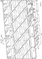
- the apparatus 10 can comprise a plurality of forming molds 20 as shown in Fig. 4 .
- Each forming mold 20 can comprise a leading edge 30 extending in the cross direction CD.
- the cross direction CD is orthogonal to the machine direction MD.
- the leading edge 30 can be thought of as the part of the forming mold 20 that leads the mold 20 as the mold 20 moves in the machine direction.
- Each forming mold 20 can also comprise a trailing edge 40 extending in the cross direction CD. The trailing edge 40 follows the leading edge 30 through the apparatus 10 and process.
- the forming molds 20 can have a mold face 50 extending from the leading edge 30 to the trailing edge 40 in the machine direction.
- the mold face 50 is the surface of the mold facing upward toward the first nozzle 390 upon which the first web 250 is placed and formed.
- the forming molds 20 can have a plurality of first recesses 60 in the mold face 50.
- the first recesses 60 can be positioned across the mold face 50 in the cross direction CD. Providing a plurality of first recesses 60 in the cross direction can be practical for increasing the capacity of apparatus 10 in a cost-effective manner since all of the drive elements are needed regardless of the width of the apparatus in the cross direction CD.
- the plurality of first recesses 60 can be aligned with one another in the cross direction CD. This may provide for simple dosing of the first substrate treatment agent.
- the first recesses 60 can be staggered relative to one another, which might be practical depending on the mechanism used to dispense the first substrate treatment agent.
- the first recesses 60 can be in fluid communication with a first vacuum duct 70.
- the first vacuum duct 70 serves to provide an exit for the air in the first recess 60 as the first web 250 is conformed to the first recess 60.
- the first web 250 can be conformed to the first recess 60 by applying a pressure greater than atmospheric pressure to the upper surface of the first web 250 or apply a pressure less than atmospheric pressure to the lower surface of the first web 250. To apply a pressure less than atmospheric pressure to the lower surface of the first web 250 a vacuum can be applied to the first vacuum duct 70.
- the first recesses can have a plan view area from about 4 mm 2 to about 10000 mm 2 .
- the first recesses can have a plan view area from about 800 mm 2 to about 5000 mm 2 .
- the forming molds 20 have a leading face 80 extending from the leading edge 30 in a direction away from the mold face 50.
- the leading face 80 is the face of the forming mold 20 facing in the machine direction MD. All, a portion of, or portions of the leading face 80 can be recessed relative to the mold face 50 proximal the leading edge. That is, all, a portion of, or portions of the leading face 80 can be undercut relative to the leading edge.
- the forming molds 20 also have a trailing face 90.
- the leading face 80 precedes the trailing face 90 as the forming mold 20 moves in the machine direction.
- the leading face 80 and the trailing face 90 of an individual forming molds 20 oppose one another in the machine direction.
- the trailing face 90 extends from the trailing edge 40 in a direction away from the mold face 50.
- all, a portion of, or portions of the trailing face 90 can be recessed relative to the mold face 50 proximal the trailing edge 40.
- the plurality of forming molds 20 can be arranged leading edge 30 to trailing edge 40 as a first mold belt 100.
- Forming molds 20 arranged next to one another can be positioned such that the trailing edge 40 of a downstream forming mold 20 is next to the leading edge 30 of an upstream forming mold 20.
- the trailing edge 40 of the upstream forming mold 20 is next to a leading edge 30 of the next forming mold 20 upstream.
- Trailing edge 40 to leading edge 30, the pattern repeats until the trailing edge 40 of the last up stream forming mold 20 is next to the leading edge 30 of the leading downstream mold 20 to complete the first mold belt 100, the same as a chain on a bicycle.
- the forming molds 20 can have opposing ends 140 in the cross direction CD. Proximal each opposing end 140 there can be one or more apertures 110 in fluid communication with a second vacuum duct 120. Vacuum can be applied to the second vacuum duct 120 to create a vacuum at or in the apertures 110 at the opposing ends 140 to hold down the first web 250 to the opposing ends 140 of the mold face 50. Vacuum in either or both of the vacuum ducts can be provided a negative gage pressure from about 5 mbar to about to about 500 mbar. Vacuum in the second vacuum duct can bet set at a negative gage pressure from about 5 mbar to about 150 mbar below atmospheric pressure.
- Each of the apertures 110 can have an area from about 0.1 mm 2 to about 2 mm 2 .
- the bottom of the recesses can be provided with apertures connected to the vacuum duct and the apertures can have an area from about 0.1 mm 2 to about 2 mm 2 .
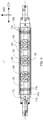
- FIG. 5 A top view of a forming mold 20 is shown in Fig. 5 .
- leading face 80 and or trailing face 90 of the forming molds 20 being undercut relative to the mold face 50 provides for space between the forming molds 20 that allows forming molds 20 next to one another to be folded towards one another as such adjacent forming molds 20 traverse by or over a curve of a roller 310 in the machine direction MD along a curved path, for instance as shown in Fig. 6 .
- the inflection axis 190 is at or between the trailing edge of the leading mold 200 and the leading edge of the trailing mold 210.
- the trailing mold 210 is upstream of the leading mold 200.
- the trailing mold 210 follows the leading mold 200 in the machine direction MD.
- Pairs of forming molds 20 can be thought of as having a first position and a second position.
- first position the trailing face 90 of the leading mold 200 is rotationally away from the leading face 80 of the adjacent trailing mold 210 about the inflection axis 190.
- second position the trailing face 90 of the leading mold 200 is rotationally towards the leading face 80 of the adjacent trailing mold 210 about the inflection axis 190.
- the leading mold 200 and trailing mold 210 are positioned relative to one another so that the mold faces 50 of the two molds in plane with one another. That arrangement can provide for a flat, substantially continuous surface, accounting for in small gaps between leading molds 200 and trailing molds 210, to lay the first web 250 upon.
- the first web 250 can be positioned on the flat mold belt 100.
- a pressure difference for instance vacuum
- a pressure difference for instance vacuum
- a pressure difference for instance vacuum
- the first substrate treatment agent 270 can be placed into the first compartments 260. Afterwards, the second web 280 can be provided and sealed to the first web 250.
- the first compartments 260 can each have a volume from about 0.1 mL to about 50 mL.
- the trailing face 90 of a downstream forming mold 20 can rotate towards the leading face 80 of an upstream forming mold 20 about the inflection axis 190.
- the mold face 50 of the downstream forming mold 20 and the mold face 50 of the upstream forming mold 20 can form a substantially continuous polygonal surface upon which the first web 250 can be carried with only a small magnitude of strain or even zero strain on the first web 250 as it is bent across the inflection axis 190.
- a functionally insignificant discontinuity between the upstream forming mold 20 and the downstream forming mold 20 at the inflection axis 190 between the two may arise as the two forming molds 20 are pivoted towards one another about the inflection axis 190.
- the trailing face 90 of the downstream forming mold 20 and the leading face 80 of the upstream forming mold 20 rotate relatively towards one another about the inflection axis 190.
- the mold face 50 of the downstream forming mold 20 and the mold face 50 of the upstream forming mold 20 form a substantially continuous polygonal surface upon which the first web 250 can be carried with small or zero strain on the first web 250.
- the mold faces 50 of the forming molds 20 traversing the curved path form a polygonal surface. That polygonal surface is the surface upon which the first web 250 is carried.
- the trailing face 90 of the downstream forming mold 20 and the leading face 80 of the upstream forming mold 20 open up relative to one another by pivoting about the inflection axis 190.
- leading face 80 extending from the leading edge 30 can be recessed relative to the mold face 50 proximal the leading edge 30 and the trailing face 90 recessed relative to the mold face 50 proximal the trailing edge 40.
- This can be practical for allowing adjacent forming molds 20 to be bent around a curved path and still maintain a substantially continuous polygonal surface for carrying the first web 250.
- This in contrast to arrangement like that shown in Fig. 1 in which a substantial discontinuity between the downstream forming mold 20 and the upstream forming mold 20 opens up as the adjacent forming molds 20 are travel a curved path.
- leading face 80 extending from the leading edge 30 can be recessed relative to the mold face 50 proximal the leading edge 20 or the trailing face 90 extending from the trailing edge 40 can be recessed relative to the mold face 50 proximally the trailing edge 40.
- a portion or portions of the trailing face 90 of the downstream forming mold 20 that is or are recessed can be offset from the portion or portions of the leading face 80 of the upstream forming mold 20 that is or are recessed.
- the upstream forming mold 20 and downstream forming mold 20 can nest with one another as the trailing face 90 of the downstream mold and the leading face 80 of the upstream mold can move relative towards and away from one another by rotation about the inflection axis 190 at or between the trailing edge 40 and leading edge 30.
- At least a portion of the leading face 80 can be recessed relative to the mold face 20 proximal the leading edge 30 or at least a portion of the trailing face 90 can be recessed relative to the mold face 50 proximal the trailing edge 40.
- the trailing face 90 can be recessed relative to the mold face 20 proximal the trailing edge 40 and or the leading face 80 can be recessed relative to the mold face 20 proximal the leading edge 30.
- the underlying need is for there to be some space to accommodate rotation of one or both of the trailing face 90 of the downstream forming mold 20 and the leading face 80 of the upstream forming mold 20 toward one another about the inflection axis 190 to allow the first mold belt 100 to bend around a curve and have the mold faces 50 form a substantially continuous polygonal surface to carry a web or webs thereupon with little or no strain.
- the forming molds 20 can be attachable and detachable from a manifold tray 130, by way of non-limiting example as shown in Fig. 8 .
- the forming molds 20 can be comprised of an assembly of parts that are assembled by adhering, welding, joining, screwing, magnets, or otherwise engaging the parts with one another.
- the manifold tray 130 can serve to provide fluid communication between the manifold 160 and the first vacuum duct 70 and the second vacuum duct 120, if present.
- the manifold tray 130 can have manifold ducts 75 to provide fluid communication from the manifold 160 to one or both of the opposing ends 140 of the forming molds 20.
- a further benefit of the manifold tray 130 is that it can provide easy repair and replacement of individual forming molds 20 if they become worn or damaged. Further, unlike a continuous mold belt in which individual forming molds 20 cannot be individually attached and detached from the belt, forming molds 20 that are attachable and detachable from a manifold tray 130 can be easily changed in and changed out to provide the ability to manufacture of a variety of different shaped pouches 240 on the same apparatus 10 and easily the alter the proportion of manufactured pouches 240 having a particular shape.
- the first vacuum duct 70 can be in fluid communication with the manifold 160.
- Providing a manifold 160 can be practical for applying vacuum pressure from a single source to multiple locations, which can simplify manufacturing control of the apparatus.
- the plurality of forming molds 20 can traverse by or over a roller 310 with which the plurality of forming molds 20 is operatively engaged to traverse a curved path.
- the forming molds 20 can be in fluid communication with the manifold 160 or a combination of manifolds 160 upstream of the roller 310, by or along the roller 310, and downstream of the roller 310. This can be practical for keeping vacuum pressure on the first recesses 60, and apertures 110 if present, so that the first pouch 290 and the associated first web 250 and second web 280 remain engaged with the mold faces 50 and first recesses 60 as the forming molds are partially or fully inverted.
- Vacuum can be applied to the forming molds 20 in a variety of ways.
- the manifold 160 can be positioned immediately beneath the forming mold 20. If positioned as such, the path that the forming molds 20, or manifold trays 130 if provided, take as the mold belt 100 traverses a curved path may require that the forming molds 20, or manifold trays 130 if provided, has a portion extending from the bottom of the forming mold 20, or manifold tray 130 if provided, that fits into or over the manifold 160 and is sealingly engaged with the manifold 160. Or the bottom of the forming mold 20, or manifold tray 130 if provided, may have a curved surface to conform with a manifold 160 that is curved in the machine direction MD.
- a vacuum linkage 150 can be provided.
- Each of the forming molds 20 can have opposing ends 140 in the cross direction CD. At least one of the opposing ends 140 can be engaged with the vacuum linkage 150 and the first vacuum duct 70 can pass through the vacuum linkage 150 to the manifold 160.
- Providing the manifold 160 at one of the opposing ends 140 can be practical because with the manifold 160 out of the way, other structures the forming molds 20 can be slid over another surface or travel over a roller or rollers to provide bearing resistance when webs of material are bonded to one another on the forming molds 20.
- a vacuum linkage 150 can be practical since linkages have the ability to closely conform to a curve and maintain vacuum without significant leakage.
- a bicycle chain is a linkage and can conform to a chain ring having a curved perimeter.
- the shorter the vacuum linkages 150 in the machine direction MD the more closely the vacuum linkages 150 can conform to the curve of a curved manifold 160.
- the vacuum linkages 150 can be connected to one another in the machine direction MD by through pins 180.
- Each of the through pins 180 can be axially aligned with the inflection axis 190 at or between the trailing edge 40 of a leading mold 200 and the leading edge 30 of a trailing mold 210, the leading mold 200 being adjacent the trailing mold 210.
- Aligning the through pins 180 with the inflection axis 190 between adjacent forming molds 20 can be practical so that adjacent vacuum linkages 150 deform in concert with the mold faces 50 when the trailing face 90 of a leading mold 200 and the leading face 80 of an adjacent trailing mold 210 rotate towards and away from one another about the inflection axis 190. This also simplifies transmission of motive force from a drive train to the forming molds 20 to move them in the machine direction MD. Having the through pins 180 aligned with the inflection axis 190 can allow for the strain in the web carried thereupon to be small, nearly zero, or even zero.
- the through pins 180 can be engaged with a drive train 400.
- the drive train 400 can be a chain that is engaged with a driving sprocket connected to a motor. Arranged as such, the motive force applied can be applied substantially coincident with the inflection axis 190. This can provide for inflection axis 190, vacuum linkages 150, and drive train 400 to move in concert with one another along a curved path while allowing the trailing edge 40 of a leading mold 20 and the leading edge 30 of a trialing mold 210 remain in close proximity to one another and maintain a substantially continuous surface across the inflection axis 190 between adjacent forming molds 20.
- both the first vacuum duct 70 and second vacuum duct 120 can pass through the vacuum linkage 150 to the manifold 160.
- the manifold 160 can be a single chamber manifold 160. If the vacuum pressure applied to the first vacuum duct 70 needs to be different from the vacuum pressure applied to the second vacuum duct 120, a multi-chamber manifold 160 can be practical. Or if the same vacuum pressure is suitable for both vacuum ducts, a single chamber manifold 160 can be practical.
- the timing of when vacuum is applied to the vacuum ducts can be controlled by leaving open and blocking certain portions of the surface of the manifold 160 over which the vacuum ducts travel. This can be further facilitated by having the first vacuum duct 70 and the second vacuum duct 120 offset from one another in the cross direction CD and providing a manifold 160 that has a shield 170 engageable with one of the vacuum ducts. If the second vacuum duct 120 is in fluid communication with the apertures 110 located proximal the ends 140, it can be practical for the shield 170 to be engageable with the first vacuum duct 70 over a portion of the manifold 160 at a location at which the manifold 160 is in fluid communication with the second vacuum duct 120.
- the shield 170 on the manifold 160 can be used to turn on and off vacuum to vacuum duct associated with the shield.
- vacuum pressure can be applied to the second vacuum duct 120. That vacuum pressure can be transmitted by the second vacuum duct 120 to the apertures 110 located proximal the ends 140 of the forming molds 20. This can provide an effective hold down force along the edges of the first web 250 and secures the first web 250 to the mold belt 100.
- vacuum pressure can be applied to the first vacuum duct 70 to deform the first web 250 into the first recesses 60.
- the manifold 160 can have a manifold surface 220 parallel to a plane defined by the machine direction MD and the cross direction CD.
- the manifold 160 can further comprise manifold ledges 230 on opposing sides of the manifold 160 projecting out of such plane.
- the manifold surface 220 is the surface of the manifold 160 that the vacuum linkages 150 slide over thereby bring one or more of the first vacuum duct 70 and second vacuum duct 120 in fluid communication with the manifold 160.
- the forming molds 20, or manifold trays 130 if present may slide directly over this manifold surface 220 to provide fluid communication from one or both of the first vacuum duct 70 and second vacuum duct 120.
- the forming molds 20, or manifold trays 130 if employed, or vacuum linkages 150 if employed, or whatever structure is used to provide fluid communication between the manifold 160 and one or both of the first vacuum duct 70 and second vacuum duct 120, can be nested between the manifold ledges 230. This nesting can be helpful for maintaining vacuum pressure on the first vacuum duct 70 and second vacuum duct 120. Further, as the mold belt 100 is bent around a curve, since individual segments are being bent about such curve it can be difficult to provide for exact conformance between the manifold surface 220 and structure that conveys vacuum press to the first vacuum duct 70 and second vacuum duct 120.
- the manifold ledges 230 only need to project high enough above the manifold surface 220 so that the forming molds 20, or manifold trays 130 if employed, or vacuum linkages 150 if employed, or whatever structure is used to provide fluid communication between the manifold 160 and one or both of the first vacuum duct 70 and second vacuum duct 120 remain sufficiently sealed to the manifold surface 220 maintain vacuum pressure where desired.
- the manifold 160 can have a plurality of chambers having different levels of vacuum. This can allow for control of deformation of the web as it is drawn into conformance with the forming mold 20.
- the apparatus 10 can be employed to make a plurality of water soluble pouches 240.
- a water soluble first web 250 can be provided on the mold belt 100.
- the fist web 250 can be formed into the first recesses 60 to form first compartments 260 by applying a pressure difference across the first web 250.
- the pressure difference can be conveniently applied by vacuum applied to the first recesses through the first vacuum ducts 70 using a manifold tray 130 and manifold 160 as described herein or otherwise.
- a positive pressure can be applied to the top surface of the first web 250 to force the first web 250 to conform to the first recesses 60, the first recesses 60 having a vent in their base to allow air to escape as the first web is forced down into the first recess 60.
- a first substrate treatment agent 270 can be place into the first compartments 260.
- a water soluble second web 280 can be provided and sealed to the first web 250 to form an enclosed first pouch 290.
- the first pouch 290 can have a first chamber 300 defined by the deformed first web 250 and the second web 280.
- the first substrate treatment agent 270 can be between the first web 250 and the second web 280.
- the second web 280 can be above the first web 250.
- the mold belt 100 can be rolled by or over one or more rollers 310 to move the mold belt 100 along a curved path. This movement can position the first pouch 290 so that the second web 280 is below the first web. As the belt 100 rolls by or over the one or more rollers 310, one or both of the trailing face 90 of the leading mold 200 and or the leading face 80 of the trailing mold 210 can move towards one another by rotation about the inflection axis 190 at or between the trailing edge 40 of the leading mold 200 and the leading edge 30 of the trailing mold 210, the leading mold 200 being adjacent the trailing mold 210.
- the trailing face 90 of the leading mold 200 and the leading face 80 of the trailing mold 210 can both move towards one another relatively by rotation about the inflection axis 190 as well. This can be practical if both the leading face 80 and trailing face 90 of a forming mold are undercut relative to the mold face 50. This can also be practical if the forming molds 20 are provided with portions of the trailing face 90 of the downstream mold 20 that are recessed and staggered out of phase with portions of the leading face 80 of the upstream forming mold 20 that are recessed so that the downstream forming mold 20 and upstream forming mold 20 can nest with one another as they traverse a curved path.
- a water soluble third web 320 can be provided and formed into one or more second recesses 395 of a second mold belt 330 to form second compartments 340.
- a second substrate treatment agent 350 can be placed into the second compartments 340.
- the second web 280 can be sealed to the third web 320 to form an enclosed second pouch 360.
- the second pouch 360 can have a second chamber 370 containing the second substrate treatment agent 350.
- the first pouch 290 can be superposed upon and bonded to the second pouch 360 to form a superposed pouch 380.
- the first web 250 second web 280, and third web 320 can be cut so that the superposed pouches 380 are separate from one another.
- vacuum can be applied to the second vacuum duct 120 before vacuum is applied to the first vacuum duct 70.
- the second vacuum duct 120 if present, is fluid communication with the apertures 110.
- the edges of the first web 250 in the cross direction CD can be held down on the forming molds 20 before the first web 250 is drawn into the first recesses 60. This can provide for better control of the forming process and reduce the chance of uncontrolled stretching and or wrinkling.
- Each of the mold faces 50 has opposing ends in the cross direction CD.
- the forming molds 20 can have at each opposing end in the cross direction CD one or more apertures 110 in fluid communication with a second vacuum duct 120.
- One or both opposing ends can be operably engaged with a vacuum linkage 150 having a first vacuum duct 70 and second vacuum duct 120 passing therethrough to a manifold 160.
- the first vacuum duct 70 and second vacuum duct 120 can be offset from one another in the cross direction CD.
- Such an arrangement can provide for the ability to independently control application of vacuum to the particular vacuum duct. Control of vacuum can be managed with a shield 170 that is engagable with the second vacuum duct 120 over a portion of the manifold 160 at a location in which the manifold 160 is in fluid communication with the first vacuum duct 70.
- Each of the water soluble webs disclosed herein can be, by way of nonlimiting example, the film that is used in TIDE PODS, CASCADE ACTION PACS,CASCADE PLATINUM, CASCADE COMPLETE, ARIEL 3 IN 1 PODS, TIDE BOOST ORIGINAL DUO PACs, TIDE BOOST FEBREZE SPORT DUO PACS, TIDE BOOST FEE DUO PACS, TIDE BOOSE VIVID WHITE BRIGHT PACS, DASH, FAIRY (PLATINUM, ALL-IN ONE, YES (PLATINUM ALL-IN ONE, JAR (PLATINUM, ALL-IN ONE, DREFT (PLATINUM, ALL-IN ONE, manufactured by The Procter & Gamble Company, Cincinnati, Ohio, United States of America.
- the water soluble webs can have a thickness from about 20 to about 150 microns, or even about 35 to about 125 microns, or even about 50 to about 110 microns, or even about 76 microns or even about 90 microns.
- the water soluble webs can comprise polyvinyl alcohol.
- the water soluble webs can be webs supplied by Monosol under the trade references M8630, M8900, M8779, M8310, films described in US 6 166 117 and US 6 787 512 and PVA films of corresponding solubility and deformability characteristics. Further water soluble webs can be those described in US2006/0213801 , WO 2010/119022 and US6787512 .
- the substrate treatment agents disclosed herein can be by way of nonlimiting example, any of the substrate treatment agents used in the aforesaid products.
Landscapes
- Engineering & Computer Science (AREA)
- Mechanical Engineering (AREA)
- Chemical & Material Sciences (AREA)
- Physics & Mathematics (AREA)
- Fluid Mechanics (AREA)
- Chemical Kinetics & Catalysis (AREA)
- Oil, Petroleum & Natural Gas (AREA)
- Wood Science & Technology (AREA)
- Organic Chemistry (AREA)
- Manufacturing & Machinery (AREA)
- Life Sciences & Earth Sciences (AREA)
- Moulds For Moulding Plastics Or The Like (AREA)
- Blow-Moulding Or Thermoforming Of Plastics Or The Like (AREA)
- Containers And Plastic Fillers For Packaging (AREA)
- Chain Conveyers (AREA)
Claims (14)
- Appareil (10) comprenant :
une pluralité de moules de formage (20), chaque moule précité comprenant :un bord d'attaque (30) s'étendant dans une direction croisée (CD) ;un bord de fuite (40) s'étendant dans ladite direction croisée ;une face de moule (50) s'étendant dudit bord d'attaque audit bord de fuite dans une direction machine (MD) orthogonale à ladite direction croisée ;une pluralité de premiers renfoncements (60) dans ladite face de moule positionnés à travers ladite face de moule dans une direction croisée précitée, chaque premier renfoncement précité en communication fluidique avec un premier conduit de vide (70) ;une face d'attaque (80) s'étendant à partir dudit bord d'attaque dans une direction à l'écart de ladite face de moule ;une face de fuite (90) s'étendant à partir dudit bord de fuite dans une direction à l'écart de ladite face de moule ;dans lequel au moins une partie de ladite face d'attaque est renfoncée par rapport à ladite face de moule à proximité dudit bord d'attaque ou au moins une partie de ladite face de fuite est renfoncée par rapport à ladite face de moule à proximité dudit bord de fuite ;dans lequel ladite pluralité de moules de formage est agencée de bord d'attaque à bord de fuite en tant que première courroie de moules (100), dans lequel entre des moules adjacents se trouve un axe d'inflexion (190) au niveau dudit ou entre ledit bord de fuite d'un moule d'attaque (200) et ledit bord d'attaque d'un moule de fuite (210), dans lequel des paires desdits moules de formage ont une première position et une deuxième position, dans lequel dans ladite première position ladite face de fuite d'un moule d'attaque est rotationnellement à l'écart de ladite face d'attaque d'un moule de fuite adjacent autour dudit axe d'inflexion et dans ladite deuxième position ladite face de fuite dudit moule d'attaque est rotationnellement rapprochée de ladite face d'attaque dudit moule de fuite adjacent autour dudit axe d'inflexion. - Appareil selon la revendication 1, dans lequel chacun desdits moules peut être fixé et détaché d'un plateau collecteur (130).
- Appareil selon la revendication 1 ou 2, dans lequel ledit premier conduit de vide est en communication fluidique avec un collecteur (160).
- Appareil selon la revendication 3, dans lequel ladite pluralité de moules se déplace par ou sur un rouleau (310) avec lequel ladite pluralité de moules est mise fonctionnellement en prise pour se déplacer sur une trajectoire courbée et lesdits moules sont en communication fluidique avec ledit collecteur ou une combinaison de collecteurs en amont dudit rouleau, le long dudit rouleau, et en aval dudit rouleau.
- Appareil selon la revendication 4, dans lequel chacun desdits moules a des extrémités opposées (140) dans ladite direction croisée, dans lequel au moins l'une desdites extrémités est en prise fonctionnellement avec une liaison sous vide (150) et ledit premier conduit de vide passe à travers ladite liaison sous vide vers un collecteur (160).
- Appareil selon l'une quelconque des revendications 1 à 5, dans lequel chacune desdites faces de moule a des extrémités opposées dans ladite direction croisée, où à proximité de chaque extrémité opposée se trouvent une ou plusieurs ouvertures (110) en communication fluidique avec un deuxième conduit de vide (120).
- Appareil selon la revendication 6, dans lequel chacun desdits moules a des extrémités opposées (140) dans ladite direction croisée, dans lequel au moins l'une desdites extrémités est en prise fonctionnellement avec une liaison sous vide (150) et ledit premier conduit de vide et ledit deuxième conduit de vide passent à travers ladite liaison sous vide vers un collecteur (160).
- Appareil selon la revendication 7, dans lequel ledit premier conduit de vide et ledit deuxième conduit de vide sont décalés l'un de l'autre dans la direction croisée et ledit collecteur a un bouclier (170) pouvant venir en prise avec ledit premier conduit de vide par-dessus une partie dudit collecteur à un emplacement au niveau duquel ledit collecteur est en communication fluidique avec ledit deuxième conduit de vide.
- Appareil selon l'une quelconque des revendications 6 à 8, dans lequel lesdites liaisons sous vide sont reliées les unes aux autres dans ladite direction machine par des broches traversantes (180), dans lequel chaque broche traversante précitée est alignée axialement avec un axe d'inflexion (190) au niveau dudit ou entre ledit bord de fuite d'un moule d'attaque (200) et ledit bord d'attaque d'un moule de fuite (210), ledit moule d'attaque étant adjacent audit moule de fuite.
- Appareil selon la revendication 9, dans lequel lesdites broches traversantes sont en prise avec une chaîne cinématique 400.
- Appareil selon l'une quelconque des revendications 6 à 10, dans lequel ledit collecteur a une surface de collecteur (220) parallèle à un plan défini par ladite direction machine et ladite direction croisée et des rebords de collecteur (230) sur des côtés opposés de ladite surface de collecteur faisant saillie dudit plan, dans lequel lesdites liaisons sous vide sont renfoncées entre lesdits rebords de collecteur.
- Appareil selon l'une quelconque des revendications 1 à 11, dans lequel ladite pluralité de premiers renfoncements sont alignés les uns avec les autres dans ladite direction croisée.
- Appareil selon l'une quelconque des revendications 1 à 12, dans lequel au moins une partie de ladite face d'attaque est renfoncée par rapport à ladite face de moule à proximité dudit bord d'attaque et au moins une partie de ladite face de fuite est renfoncée par rapport à ladite face de moule à proximité dudit bord de fuite.
- Procédé de fabrication d'une pluralité de sachets hydrosolubles (240) comprenant les étapes consistant à :fournir l'appareil selon l'une quelconque des revendications 1 à 13 ;fournir une première nappe hydrosoluble (250) sur ladite courroie de moules ;former ladite première nappe dans lesdits premiers renfoncements pour former des premiers compartiments (260) en appliquant une différence de pression à travers ladite première nappe ;placer un premier agent de traitement de substrat (270) dans lesdits premiers compartiments ;fournir une deuxième nappe hydrosoluble (280) ;sceller ladite deuxième nappe à ladite première nappe pour former un premier sachet fermé (290) ayant une première chambre (300) contenant ledit agent de traitement de substrat, dans lequel ladite deuxième nappe est au-dessus de ladite première nappe ;faire rouler ladite courroie de moules par ou sur un ou plusieurs rouleaux (310) pour déplacer ladite courroie de moules le long d'une trajectoire courbée, ce qui positionne ledit premier sachet de sorte que ladite deuxième nappe est en dessous de ladite première nappe, dans lequel à mesure que ladite courroie de moules roule par ou sur ledit ou lesdits rouleaux l'une et/ou l'autre de ladite face de fuite d'un moule d'attaque (200) et de ladite face d'attaque d'un moule de fuite (210) se déplacent l'une vers l'autre par rotation autour d'un axe d'inflexion (190) au niveau dudit ou entre ledit bord de fuite dudit moule d'attaque et ledit bord d'attaque dudit moule de fuite, ledit moule d'attaque étant adjacent audit moule de fuite.
Applications Claiming Priority (2)
| Application Number | Priority Date | Filing Date | Title |
|---|---|---|---|
| US15/626,551 US10781000B2 (en) | 2017-06-19 | 2017-06-19 | Apparatus and process for forming water soluble pouches |
| PCT/US2018/038200 WO2018236813A1 (fr) | 2017-06-19 | 2018-06-19 | Appareil et procédé de formation de sachets hydrosolubles |
Publications (2)
| Publication Number | Publication Date |
|---|---|
| EP3642007A1 EP3642007A1 (fr) | 2020-04-29 |
| EP3642007B1 true EP3642007B1 (fr) | 2021-06-09 |
Family
ID=62875306
Family Applications (1)
| Application Number | Title | Priority Date | Filing Date |
|---|---|---|---|
| EP18740008.0A Active EP3642007B1 (fr) | 2017-06-19 | 2018-06-19 | Appareil et procede de formation de sachets hydrosolubles |
Country Status (6)
| Country | Link |
|---|---|
| US (1) | US10781000B2 (fr) |
| EP (1) | EP3642007B1 (fr) |
| JP (1) | JP7216026B2 (fr) |
| CA (1) | CA3065799C (fr) |
| HU (1) | HUE059205T2 (fr) |
| WO (1) | WO2018236813A1 (fr) |
Families Citing this family (7)
| Publication number | Priority date | Publication date | Assignee | Title |
|---|---|---|---|---|
| EP4071059A1 (fr) * | 2021-04-07 | 2022-10-12 | Fameccanica.Data S.p.A. | Unité de dosage, procédé de dosage, et machine de production d'articles de dose unique |
| EP4071060A1 (fr) * | 2021-04-07 | 2022-10-12 | Fameccanica.Data S.p.A. | Unité de dosage, procédé de dosage et machine de production d'articles de dose unitaire |
| PL4101774T3 (pl) * | 2021-06-11 | 2024-03-18 | Harro Höfliger Verpackungsmaschinen GmbH | Urządzenie uszczelniające i sposób uszczelniania opakowań |
| CA3225060A1 (fr) * | 2021-07-30 | 2023-02-02 | Hans WIPRAECHTIGER | Chaine de fabrication pour fabriquer une dosette compostable pour des produits d'infusion et systeme de mesure et de regulation de l'humidite relative d'un materiau a base de papier biodegradabl |
| US20240158113A1 (en) * | 2022-10-28 | 2024-05-16 | The Procter & Gamble Company | Process of making water-soluble unit dose articles |
| EP4406862A1 (fr) * | 2022-12-15 | 2024-07-31 | Fameccanica.Data S.p.A. | Appareil de dosage, machine de production de capsules à dose unique et procédé de dosage associé |
| NL2034969B1 (en) * | 2023-06-01 | 2024-12-10 | Eme Engel Machf En Engineering B V | Packaging system for producing pouches comprising a water-soluble foil and a fluid |
Family Cites Families (36)
| Publication number | Priority date | Publication date | Assignee | Title |
|---|---|---|---|---|
| US614847A (en) * | 1898-11-29 | Endless conveyer | ||
| US449464A (en) * | 1891-03-31 | Carrier for feeding bagasse-furnaces | ||
| US1723357A (en) * | 1927-07-19 | 1929-08-06 | Koopman Charles | Draper |
| US1883528A (en) * | 1931-01-17 | 1932-10-18 | Buck Dryer Corp | Conveyer |
| DE676557C (de) * | 1936-12-16 | 1939-06-07 | Schenck U Liebe Harkort Akt Ge | Kastenbandfoerderer |
| US2689638A (en) * | 1949-06-14 | 1954-09-21 | Mojonnier Bros Co | Conveyer |
| DE1461915C3 (de) * | 1965-04-02 | 1979-10-25 | Tetra Pak Rausing & Co Kg, 6203 Hochheim | Vorrichtung zur Herstellung von Quaderpackungen |
| US3381445A (en) * | 1965-09-14 | 1968-05-07 | Clarence W. Vogt | Package forming apparatus |
| US3592334A (en) * | 1966-10-27 | 1971-07-13 | Gen Logistics | Differential pressure conveyors |
| FR1552043A (fr) * | 1967-11-06 | 1969-01-03 | ||
| JPS617130A (ja) * | 1984-06-18 | 1986-01-13 | Anritsu Corp | 物品分類装置 |
| US4718541A (en) * | 1985-11-01 | 1988-01-12 | Wilding Edwin L | Tobacco feeder with slat conveyors |
| US4729469A (en) * | 1985-11-15 | 1988-03-08 | Lapeyre James M | Flat top conveyor belt |
| US5074102A (en) * | 1989-10-26 | 1991-12-24 | American Cyanamid Company | Flat track modified soft shell capsule filling machine |
| US5042647A (en) * | 1990-05-31 | 1991-08-27 | Griffin & Company | Overlapping, non-leaking conveyor slat for dry bulk materials |
| US5264230A (en) * | 1992-08-04 | 1993-11-23 | David Swanson | Process for making toroidal wieners |
| US5682733A (en) * | 1996-05-09 | 1997-11-04 | Perrone; Aldo | Apparatus for enrobing tablets |
| DE69801547T2 (de) | 1997-06-11 | 2002-04-18 | Kuraray Co., Ltd | Wasserlöslicher Folie |
| JPH11246019A (ja) * | 1998-03-06 | 1999-09-14 | Tsubakimoto Chain Co | 搬送用歯付ベルト及び、歯付ベルト用被覆除去治具 |
| DE19912491A1 (de) * | 1999-03-19 | 2000-09-28 | Multivac Haggenmueller Gmbh | Verpackungsmaschine |
| CA2426645C (fr) | 2000-11-27 | 2008-06-10 | The Procter & Gamble Company | Sachet de detergent comportant des compartiments superposes ou superposables |
| US8283300B2 (en) | 2000-11-27 | 2012-10-09 | The Procter & Gamble Company | Detergent products, methods and manufacture |
| US7125828B2 (en) | 2000-11-27 | 2006-10-24 | The Procter & Gamble Company | Detergent products, methods and manufacture |
| MXPA03006883A (es) | 2001-01-31 | 2003-11-13 | Procter & Gamble | Procedimiento para la fabricacion de bolsas. |
| BR0206924A (pt) | 2001-01-31 | 2004-07-06 | Procter & Gamble | Método e aparelho para a formação de pelìculas |
| DE60204133T2 (de) | 2002-06-28 | 2006-02-23 | The Procter & Gamble Company, Cincinnati | Verfahren und Vorrichtung zur Herstellung von Beuteln |
| US7022656B2 (en) | 2003-03-19 | 2006-04-04 | Monosol, Llc. | Water-soluble copolymer film packet |
| EP1670693B1 (fr) | 2003-10-07 | 2008-04-16 | Henkel Kommanditgesellschaft auf Aktien | Portion d'agent emballee dans une pellicule et procede de fabrication |
| US20100025200A1 (en) * | 2006-11-13 | 2010-02-04 | Sergio Fandella | Hingeless belt |
| US8048318B1 (en) | 2007-10-18 | 2011-11-01 | Heritage Environmental Services, Llc | Recovering packaged ingredients from multi-component product packets |
| BRPI1011346A2 (pt) | 2009-04-16 | 2016-10-18 | Unilever Nv | partícula de polímero, composição tensoativa, processos de formação de partículas de polímero, e, uso das mesmas |
| GB2475538B (en) | 2009-11-23 | 2011-11-23 | Rideau Machinery Inc | Improvements to continuous motion rotary thermoforming of soluble pouches |
| US9809336B2 (en) * | 2012-02-28 | 2017-11-07 | The Procter & Gamble Company | Method for forming packages |
| JP6178848B2 (ja) * | 2012-06-23 | 2017-08-09 | リデュー マシーナリー インク | 可溶性のパウチの回転可能な連続成型動作の改良 |
| CA2943138A1 (fr) | 2015-09-25 | 2017-03-25 | Multi-Pack Solutions, LLC | Machine de conditionnement dotee de mecanismes de deplacement controlables de maniere independante |
| US10702894B2 (en) * | 2016-06-24 | 2020-07-07 | The Procter & Gamble Company | Seal cleaner and process for soluble unit dose pouches containing granular composition |
-
2017
- 2017-06-19 US US15/626,551 patent/US10781000B2/en active Active
-
2018
- 2018-06-19 WO PCT/US2018/038200 patent/WO2018236813A1/fr not_active Ceased
- 2018-06-19 CA CA3065799A patent/CA3065799C/fr active Active
- 2018-06-19 JP JP2019567369A patent/JP7216026B2/ja active Active
- 2018-06-19 EP EP18740008.0A patent/EP3642007B1/fr active Active
- 2018-06-19 HU HUE18740008A patent/HUE059205T2/hu unknown
Non-Patent Citations (1)
| Title |
|---|
| None * |
Also Published As
| Publication number | Publication date |
|---|---|
| US10781000B2 (en) | 2020-09-22 |
| EP3642007A1 (fr) | 2020-04-29 |
| JP2020527511A (ja) | 2020-09-10 |
| CA3065799A1 (fr) | 2018-12-27 |
| HUE059205T2 (hu) | 2022-10-28 |
| CA3065799C (fr) | 2022-08-16 |
| US20180362193A1 (en) | 2018-12-20 |
| JP7216026B2 (ja) | 2023-01-31 |
| WO2018236813A1 (fr) | 2018-12-27 |
Similar Documents
| Publication | Publication Date | Title |
|---|---|---|
| EP3642007B1 (fr) | Appareil et procede de formation de sachets hydrosolubles | |
| US7552815B2 (en) | Method for pivoting plate elements and device for applying said method | |
| JP6178848B2 (ja) | 可溶性のパウチの回転可能な連続成型動作の改良 | |
| US20180290774A1 (en) | Moving filling nozzles on a rotatable forming machine | |
| EP2819923B1 (fr) | Appareil de formation de paquets et système de remplissage | |
| CA1046817A (fr) | Methode et materiel pour l'obtention de recipients rempils et scelles | |
| WO2004087502A2 (fr) | Formeuse-remplisseuse-scelleuse rapide a action continue | |
| JPH03118145A (ja) | 流体パッケージ製造装置 | |
| MX2014010071A (es) | Metodo para formar envases. | |
| US7325386B2 (en) | Double action vertical form-fill-seal apparatus | |
| JPH08577B2 (ja) | 複数の同期駆動手段を有する、特にブリスターパック調整用包装機械 | |
| CN105636871A (zh) | 贴标装置 | |
| CN113453986B (zh) | 用于生产管状包装体的设备和方法 | |
| US6883294B2 (en) | Method and device for the packaging of flat objects | |
| RS64255B1 (sr) | Mašina za pakovanje za pakovanje papirnih rolni | |
| ITBO20090494A1 (it) | Metodo e apparecchiatura per applicare tagliandi su prodotti di consumo | |
| GB2520306A (en) | Improvements to rotatable forming and filling of water-soluble pouches | |
| US20230415367A1 (en) | Method for transverse cutting of a water-soluble tape | |
| ITTO960806A1 (it) | Dispositivo per applicare bande di strappo | |
| HK1201799B (en) | Apparatus for forming packages and filling system | |
| HK1201800B (en) | Method for forming packages |
Legal Events
| Date | Code | Title | Description |
|---|---|---|---|
| STAA | Information on the status of an ep patent application or granted ep patent |
Free format text: STATUS: UNKNOWN |
|
| STAA | Information on the status of an ep patent application or granted ep patent |
Free format text: STATUS: THE INTERNATIONAL PUBLICATION HAS BEEN MADE |
|
| PUAI | Public reference made under article 153(3) epc to a published international application that has entered the european phase |
Free format text: ORIGINAL CODE: 0009012 |
|
| STAA | Information on the status of an ep patent application or granted ep patent |
Free format text: STATUS: REQUEST FOR EXAMINATION WAS MADE |
|
| 17P | Request for examination filed |
Effective date: 20191220 |
|
| AK | Designated contracting states |
Kind code of ref document: A1 Designated state(s): AL AT BE BG CH CY CZ DE DK EE ES FI FR GB GR HR HU IE IS IT LI LT LU LV MC MK MT NL NO PL PT RO RS SE SI SK SM TR |
|
| AX | Request for extension of the european patent |
Extension state: BA ME |
|
| DAV | Request for validation of the european patent (deleted) | ||
| DAX | Request for extension of the european patent (deleted) | ||
| GRAP | Despatch of communication of intention to grant a patent |
Free format text: ORIGINAL CODE: EPIDOSNIGR1 |
|
| STAA | Information on the status of an ep patent application or granted ep patent |
Free format text: STATUS: GRANT OF PATENT IS INTENDED |
|
| INTG | Intention to grant announced |
Effective date: 20210112 |
|
| GRAS | Grant fee paid |
Free format text: ORIGINAL CODE: EPIDOSNIGR3 |
|
| GRAA | (expected) grant |
Free format text: ORIGINAL CODE: 0009210 |
|
| STAA | Information on the status of an ep patent application or granted ep patent |
Free format text: STATUS: THE PATENT HAS BEEN GRANTED |
|
| AK | Designated contracting states |
Kind code of ref document: B1 Designated state(s): AL AT BE BG CH CY CZ DE DK EE ES FI FR GB GR HR HU IE IS IT LI LT LU LV MC MK MT NL NO PL PT RO RS SE SI SK SM TR |
|
| REG | Reference to a national code |
Ref country code: GB Ref legal event code: FG4D |
|
| REG | Reference to a national code |
Ref country code: CH Ref legal event code: EP Ref country code: AT Ref legal event code: REF Ref document number: 1400096 Country of ref document: AT Kind code of ref document: T Effective date: 20210615 |
|
| REG | Reference to a national code |
Ref country code: DE Ref legal event code: R096 Ref document number: 602018018440 Country of ref document: DE |
|
| REG | Reference to a national code |
Ref country code: IE Ref legal event code: FG4D Ref country code: NL Ref legal event code: FP |
|
| REG | Reference to a national code |
Ref country code: LT Ref legal event code: MG9D |
|
| PG25 | Lapsed in a contracting state [announced via postgrant information from national office to epo] |
Ref country code: BG Free format text: LAPSE BECAUSE OF FAILURE TO SUBMIT A TRANSLATION OF THE DESCRIPTION OR TO PAY THE FEE WITHIN THE PRESCRIBED TIME-LIMIT Effective date: 20210909 Ref country code: FI Free format text: LAPSE BECAUSE OF FAILURE TO SUBMIT A TRANSLATION OF THE DESCRIPTION OR TO PAY THE FEE WITHIN THE PRESCRIBED TIME-LIMIT Effective date: 20210609 Ref country code: HR Free format text: LAPSE BECAUSE OF FAILURE TO SUBMIT A TRANSLATION OF THE DESCRIPTION OR TO PAY THE FEE WITHIN THE PRESCRIBED TIME-LIMIT Effective date: 20210609 Ref country code: LT Free format text: LAPSE BECAUSE OF FAILURE TO SUBMIT A TRANSLATION OF THE DESCRIPTION OR TO PAY THE FEE WITHIN THE PRESCRIBED TIME-LIMIT Effective date: 20210609 |
|
| REG | Reference to a national code |
Ref country code: AT Ref legal event code: MK05 Ref document number: 1400096 Country of ref document: AT Kind code of ref document: T Effective date: 20210609 |
|
| PG25 | Lapsed in a contracting state [announced via postgrant information from national office to epo] |
Ref country code: NO Free format text: LAPSE BECAUSE OF FAILURE TO SUBMIT A TRANSLATION OF THE DESCRIPTION OR TO PAY THE FEE WITHIN THE PRESCRIBED TIME-LIMIT Effective date: 20210909 Ref country code: LV Free format text: LAPSE BECAUSE OF FAILURE TO SUBMIT A TRANSLATION OF THE DESCRIPTION OR TO PAY THE FEE WITHIN THE PRESCRIBED TIME-LIMIT Effective date: 20210609 Ref country code: SE Free format text: LAPSE BECAUSE OF FAILURE TO SUBMIT A TRANSLATION OF THE DESCRIPTION OR TO PAY THE FEE WITHIN THE PRESCRIBED TIME-LIMIT Effective date: 20210609 Ref country code: RS Free format text: LAPSE BECAUSE OF FAILURE TO SUBMIT A TRANSLATION OF THE DESCRIPTION OR TO PAY THE FEE WITHIN THE PRESCRIBED TIME-LIMIT Effective date: 20210609 Ref country code: GR Free format text: LAPSE BECAUSE OF FAILURE TO SUBMIT A TRANSLATION OF THE DESCRIPTION OR TO PAY THE FEE WITHIN THE PRESCRIBED TIME-LIMIT Effective date: 20210910 |
|
| PG25 | Lapsed in a contracting state [announced via postgrant information from national office to epo] |
Ref country code: CZ Free format text: LAPSE BECAUSE OF FAILURE TO SUBMIT A TRANSLATION OF THE DESCRIPTION OR TO PAY THE FEE WITHIN THE PRESCRIBED TIME-LIMIT Effective date: 20210609 Ref country code: AT Free format text: LAPSE BECAUSE OF FAILURE TO SUBMIT A TRANSLATION OF THE DESCRIPTION OR TO PAY THE FEE WITHIN THE PRESCRIBED TIME-LIMIT Effective date: 20210609 Ref country code: SM Free format text: LAPSE BECAUSE OF FAILURE TO SUBMIT A TRANSLATION OF THE DESCRIPTION OR TO PAY THE FEE WITHIN THE PRESCRIBED TIME-LIMIT Effective date: 20210609 Ref country code: RO Free format text: LAPSE BECAUSE OF FAILURE TO SUBMIT A TRANSLATION OF THE DESCRIPTION OR TO PAY THE FEE WITHIN THE PRESCRIBED TIME-LIMIT Effective date: 20210609 Ref country code: PT Free format text: LAPSE BECAUSE OF FAILURE TO SUBMIT A TRANSLATION OF THE DESCRIPTION OR TO PAY THE FEE WITHIN THE PRESCRIBED TIME-LIMIT Effective date: 20211011 Ref country code: EE Free format text: LAPSE BECAUSE OF FAILURE TO SUBMIT A TRANSLATION OF THE DESCRIPTION OR TO PAY THE FEE WITHIN THE PRESCRIBED TIME-LIMIT Effective date: 20210609 Ref country code: ES Free format text: LAPSE BECAUSE OF FAILURE TO SUBMIT A TRANSLATION OF THE DESCRIPTION OR TO PAY THE FEE WITHIN THE PRESCRIBED TIME-LIMIT Effective date: 20210609 Ref country code: SK Free format text: LAPSE BECAUSE OF FAILURE TO SUBMIT A TRANSLATION OF THE DESCRIPTION OR TO PAY THE FEE WITHIN THE PRESCRIBED TIME-LIMIT Effective date: 20210609 |
|
| REG | Reference to a national code |
Ref country code: CH Ref legal event code: PL |
|
| PG25 | Lapsed in a contracting state [announced via postgrant information from national office to epo] |
Ref country code: PL Free format text: LAPSE BECAUSE OF FAILURE TO SUBMIT A TRANSLATION OF THE DESCRIPTION OR TO PAY THE FEE WITHIN THE PRESCRIBED TIME-LIMIT Effective date: 20210609 |
|
| REG | Reference to a national code |
Ref country code: BE Ref legal event code: MM Effective date: 20210630 |
|
| REG | Reference to a national code |
Ref country code: DE Ref legal event code: R097 Ref document number: 602018018440 Country of ref document: DE |
|
| PG25 | Lapsed in a contracting state [announced via postgrant information from national office to epo] |
Ref country code: MC Free format text: LAPSE BECAUSE OF FAILURE TO SUBMIT A TRANSLATION OF THE DESCRIPTION OR TO PAY THE FEE WITHIN THE PRESCRIBED TIME-LIMIT Effective date: 20210609 Ref country code: LU Free format text: LAPSE BECAUSE OF NON-PAYMENT OF DUE FEES Effective date: 20210619 |
|
| PLBE | No opposition filed within time limit |
Free format text: ORIGINAL CODE: 0009261 |
|
| STAA | Information on the status of an ep patent application or granted ep patent |
Free format text: STATUS: NO OPPOSITION FILED WITHIN TIME LIMIT |
|
| PG25 | Lapsed in a contracting state [announced via postgrant information from national office to epo] |
Ref country code: LI Free format text: LAPSE BECAUSE OF NON-PAYMENT OF DUE FEES Effective date: 20210630 Ref country code: IE Free format text: LAPSE BECAUSE OF NON-PAYMENT OF DUE FEES Effective date: 20210619 Ref country code: DK Free format text: LAPSE BECAUSE OF FAILURE TO SUBMIT A TRANSLATION OF THE DESCRIPTION OR TO PAY THE FEE WITHIN THE PRESCRIBED TIME-LIMIT Effective date: 20210609 Ref country code: CH Free format text: LAPSE BECAUSE OF NON-PAYMENT OF DUE FEES Effective date: 20210630 |
|
| 26N | No opposition filed |
Effective date: 20220310 |
|
| PG25 | Lapsed in a contracting state [announced via postgrant information from national office to epo] |
Ref country code: AL Free format text: LAPSE BECAUSE OF FAILURE TO SUBMIT A TRANSLATION OF THE DESCRIPTION OR TO PAY THE FEE WITHIN THE PRESCRIBED TIME-LIMIT Effective date: 20210609 |
|
| PG25 | Lapsed in a contracting state [announced via postgrant information from national office to epo] |
Ref country code: IT Free format text: LAPSE BECAUSE OF FAILURE TO SUBMIT A TRANSLATION OF THE DESCRIPTION OR TO PAY THE FEE WITHIN THE PRESCRIBED TIME-LIMIT Effective date: 20210609 Ref country code: BE Free format text: LAPSE BECAUSE OF NON-PAYMENT OF DUE FEES Effective date: 20210630 |
|
| REG | Reference to a national code |
Ref country code: HU Ref legal event code: AG4A Ref document number: E059205 Country of ref document: HU |
|
| P01 | Opt-out of the competence of the unified patent court (upc) registered |
Effective date: 20230429 |
|
| PG25 | Lapsed in a contracting state [announced via postgrant information from national office to epo] |
Ref country code: CY Free format text: LAPSE BECAUSE OF FAILURE TO SUBMIT A TRANSLATION OF THE DESCRIPTION OR TO PAY THE FEE WITHIN THE PRESCRIBED TIME-LIMIT Effective date: 20210609 |
|
| PG25 | Lapsed in a contracting state [announced via postgrant information from national office to epo] |
Ref country code: MK Free format text: LAPSE BECAUSE OF FAILURE TO SUBMIT A TRANSLATION OF THE DESCRIPTION OR TO PAY THE FEE WITHIN THE PRESCRIBED TIME-LIMIT Effective date: 20210609 |
|
| PG25 | Lapsed in a contracting state [announced via postgrant information from national office to epo] |
Ref country code: TR Free format text: LAPSE BECAUSE OF FAILURE TO SUBMIT A TRANSLATION OF THE DESCRIPTION OR TO PAY THE FEE WITHIN THE PRESCRIBED TIME-LIMIT Effective date: 20210609 |
|
| PG25 | Lapsed in a contracting state [announced via postgrant information from national office to epo] |
Ref country code: MT Free format text: LAPSE BECAUSE OF FAILURE TO SUBMIT A TRANSLATION OF THE DESCRIPTION OR TO PAY THE FEE WITHIN THE PRESCRIBED TIME-LIMIT Effective date: 20210609 |
|
| PGFP | Annual fee paid to national office [announced via postgrant information from national office to epo] |
Ref country code: NL Payment date: 20250516 Year of fee payment: 8 |
|
| PGFP | Annual fee paid to national office [announced via postgrant information from national office to epo] |
Ref country code: DE Payment date: 20250429 Year of fee payment: 8 |
|
| PGFP | Annual fee paid to national office [announced via postgrant information from national office to epo] |
Ref country code: GB Payment date: 20250501 Year of fee payment: 8 |
|
| PGFP | Annual fee paid to national office [announced via postgrant information from national office to epo] |
Ref country code: HU Payment date: 20250529 Year of fee payment: 8 Ref country code: FR Payment date: 20250508 Year of fee payment: 8 |