EP3642523B1 - Dichtungsmanschette für eine rohrschelle und rohrschelle mit einer derartigen dichtungsmanschette - Google Patents
Dichtungsmanschette für eine rohrschelle und rohrschelle mit einer derartigen dichtungsmanschette Download PDFInfo
- Publication number
- EP3642523B1 EP3642523B1 EP18732050.2A EP18732050A EP3642523B1 EP 3642523 B1 EP3642523 B1 EP 3642523B1 EP 18732050 A EP18732050 A EP 18732050A EP 3642523 B1 EP3642523 B1 EP 3642523B1
- Authority
- EP
- European Patent Office
- Prior art keywords
- sealing
- sealing sleeve
- sealing lip
- lips
- lip
- Prior art date
- Legal status (The legal status is an assumption and is not a legal conclusion. Google has not performed a legal analysis and makes no representation as to the accuracy of the status listed.)
- Active
Links
Images
Classifications
-
- F—MECHANICAL ENGINEERING; LIGHTING; HEATING; WEAPONS; BLASTING
- F16—ENGINEERING ELEMENTS AND UNITS; GENERAL MEASURES FOR PRODUCING AND MAINTAINING EFFECTIVE FUNCTIONING OF MACHINES OR INSTALLATIONS; THERMAL INSULATION IN GENERAL
- F16L—PIPES; JOINTS OR FITTINGS FOR PIPES; SUPPORTS FOR PIPES, CABLES OR PROTECTIVE TUBING; MEANS FOR THERMAL INSULATION IN GENERAL
- F16L21/00—Joints with sleeve or socket
- F16L21/002—Sleeves or nipples for pipes of the same diameter; Reduction pieces
- F16L21/005—Sleeves or nipples for pipes of the same diameter; Reduction pieces made of elastic material, e.g. partly or completely surrounded by clamping devices
-
- F—MECHANICAL ENGINEERING; LIGHTING; HEATING; WEAPONS; BLASTING
- F16—ENGINEERING ELEMENTS AND UNITS; GENERAL MEASURES FOR PRODUCING AND MAINTAINING EFFECTIVE FUNCTIONING OF MACHINES OR INSTALLATIONS; THERMAL INSULATION IN GENERAL
- F16L—PIPES; JOINTS OR FITTINGS FOR PIPES; SUPPORTS FOR PIPES, CABLES OR PROTECTIVE TUBING; MEANS FOR THERMAL INSULATION IN GENERAL
- F16L17/00—Joints with packing adapted to sealing by fluid pressure
- F16L17/02—Joints with packing adapted to sealing by fluid pressure with sealing rings arranged between outer surface of pipe and inner surface of sleeve or socket
- F16L17/03—Joints with packing adapted to sealing by fluid pressure with sealing rings arranged between outer surface of pipe and inner surface of sleeve or socket having annular axial lips
-
- F—MECHANICAL ENGINEERING; LIGHTING; HEATING; WEAPONS; BLASTING
- F16—ENGINEERING ELEMENTS AND UNITS; GENERAL MEASURES FOR PRODUCING AND MAINTAINING EFFECTIVE FUNCTIONING OF MACHINES OR INSTALLATIONS; THERMAL INSULATION IN GENERAL
- F16L—PIPES; JOINTS OR FITTINGS FOR PIPES; SUPPORTS FOR PIPES, CABLES OR PROTECTIVE TUBING; MEANS FOR THERMAL INSULATION IN GENERAL
- F16L17/00—Joints with packing adapted to sealing by fluid pressure
- F16L17/02—Joints with packing adapted to sealing by fluid pressure with sealing rings arranged between outer surface of pipe and inner surface of sleeve or socket
- F16L17/04—Joints with packing adapted to sealing by fluid pressure with sealing rings arranged between outer surface of pipe and inner surface of sleeve or socket with longitudinally split or divided sleeve
-
- F—MECHANICAL ENGINEERING; LIGHTING; HEATING; WEAPONS; BLASTING
- F16—ENGINEERING ELEMENTS AND UNITS; GENERAL MEASURES FOR PRODUCING AND MAINTAINING EFFECTIVE FUNCTIONING OF MACHINES OR INSTALLATIONS; THERMAL INSULATION IN GENERAL
- F16L—PIPES; JOINTS OR FITTINGS FOR PIPES; SUPPORTS FOR PIPES, CABLES OR PROTECTIVE TUBING; MEANS FOR THERMAL INSULATION IN GENERAL
- F16L21/00—Joints with sleeve or socket
- F16L21/02—Joints with sleeve or socket with elastic sealing rings between pipe and sleeve or between pipe and socket, e.g. with rolling or other prefabricated profiled rings
Definitions
- the invention relates to an annular sealing sleeve for a pipe clamp, wherein the sealing sleeve has on an inside a first sealing lip with a first cross-sectional geometry and a second sealing lip with a second cross-sectional geometry.
- the invention further relates to a pipe clamp with such a sealing sleeve.
- Pipe clamps are used, for example, in the form of pipe couplings as a compact and reliable means of connecting smooth-ended pipes.
- the pipe clamps can be used to connect plastic and metal pipes, but especially stainless steel pipes or pipes made of materials such as glass, stoneware or concrete.
- a sealing sleeve In conjunction with a sealing sleeve, a fluid-tight connection is achieved, so that pressure-tight lines for solid, liquid or gaseous media can be created using the pipes connected via pipe clamps.
- a sealing sleeve is known with two opposing main sealing lips, which point inwards and are completely resiliently mounted on a jacket.
- the main sealing lips each have several small steps or elevations on the outside.
- WO 88/07644 A1 specifies a sealing sleeve with an inward-pointing spring leg that forms a first sealing lip. Further out there are several additional ones arranged adjacent to one another Sealing lips of the same cross-section are provided, which do not sit on the spring leg.
- the invention is based on the object of providing a sealing sleeve for a pipe clamp and a pipe clamp which enables high tightness at both high and low pressures.
- annular sealing sleeve for a pipe clamp, wherein the sealing sleeve has on an inside in at least one axial end region a first sealing lip with a first cross-sectional geometry and a second sealing lip with a second cross-sectional geometry, the first cross-sectional geometry and the second cross-sectional geometry being different, the first Sealing lip has a greater extent in the axial direction than in the radial direction and the second sealing lip has an equal or smaller extent in the axial direction than in the radial direction, the second cross-sectional geometry tapering in the radial direction, namely part-circular or pyramid-shaped with a rounded or pointed head area is, whereby the second sealing lip acts like an O-ring, it is provided according to the invention that the first sealing lip is stiffer than the second sealing lip due to its cross-sectional geometry.
- the axial and radial directions refer to the shape of the annular sealing sleeve or the pipes connected to it.
- the corresponding design of the different cross-sectional geometries results in different properties for the first sealing lip and the second sealing lip.
- the first sealing lip is stiffer than the second sealing lip due to its cross-sectional geometry.
- the first sealing lip which has a greater extent in the axial direction than in the radial direction, lies on a surface of the pipe relatively flat, thus creating a large-area seal with relatively low pressure.
- the second sealing lip on the other hand, lies like an O-ring only over a relatively small contact surface on the surface of the pipe and therefore with a correspondingly high pressure.
- the second sealing lip is easier to deform and can therefore adapt well to rougher surfaces. Due to the different cross-sectional geometries of the first and second sealing lips, a very reliable seal is achieved in the end region of the sealing sleeve.
- first sealing lip is inclined inwards in the axial direction away from the second sealing lip.
- the first sealing lips are inclined towards a gap between two interconnected pipes. Due to this inclination axially inwards, the first sealing lip is pressed ever more strongly against the surface of the pipe as the pressure within the pipe increases, so that a further improved seal is obtained as the pressure increases.
- the second sealing lip is arranged axially further outward than the first sealing lip.
- the first sealing lip is therefore directly exposed to a pressure prevailing within the pipe and thus represents the first sealing stage, while the second sealing lip serves as additional protection, but itself has to withstand such a reduced pressure.
- further sealing lips with the same cross-sectional geometry as the second sealing lip are arranged adjacent to the second sealing lip.
- the further sealing lips and the second sealing lip can be designed to be relatively thin and accordingly elastic, with multiple sealing being achieved by the plurality of sealing lips.
- the sealing lips can adapt well to a rough surface and thus ensure a secure seal even then.
- the additional sealing lips further increase the reliability of the seal that can be achieved.
- the second cross-sectional geometry is partially circular or pyramid-shaped with a rounded or pointed head area.
- the second sealing lips act like O-rings and can nestle well against a surface of the pipe. At the same time, they are able to build up sufficient sealing forces in the radial direction, whereas they are relatively elastic in the axial direction.
- the sealing sleeve is preferably constructed symmetrically, with a combination of a first sealing lip and a second sealing lip and optionally further sealing lips being arranged on each axial end region.
- first sealing lip and second sealing lip are arranged on each axial end region.
- first sealing lips are axially further inward than the second sealing lips and possibly further sealing lips.
- the first sealing lips which are stiffer than the second sealing lip due to their cross-sectional geometry, and the further sealing lips thus act as a first seal, which is acted upon by the internal pipe pressure.
- the second sealing lips and further sealing lips then create a further downstream seal.
- the additional sealing lips arranged axially further outward extend less radially inward than the first sealing lips.
- the first sealing lip first comes into contact with the surface of the pipe and then the second sealing lip and then the further sealing lips. This ensures that when the pipe clamp is tightened, the first sealing lip in particular is pressed onto the pipe surface with sufficient contact pressure in order to achieve a sufficient sealing effect.
- the... The sealing sleeve is then deformed in such a way that the other sealing lips also rest on the surface of the pipe and achieve an additional seal. The first sealing lip and the second sealing lip then rest against the pipe surface with particularly high force and produce a very high seal.
- first sealing lip and the second sealing lip extend radially further inwards than at least one of the further sealing lips.
- first sealing lip and the second sealing lip even extend the same distance radially inwards, i.e. come into contact with the surface of the pipe at the same time, so that a double seal is always guaranteed.
- the sealing sleeve has a central region with a constant material thickness between the first sealing lips, the sealing element being thinner in this region than in the region of the sealing lips.
- the middle area essentially serves to connect the areas with the sealing lips to one another and, if necessary, to bridge a gap between the pipe ends.
- This area is made thinner than the area with the sealing lips results in material savings. This leads to low weight and low manufacturing costs.
- the smaller material thickness makes it possible, for example, to arrange a band insert on the radial inside in the central region of the sealing sleeve. This can then serve, for example, as a stiffener and as protection against mechanical stress.
- the tape insert can counteract the elastic sealing sleeve being drawn into the gap between the interconnected pipes.
- a radial outside of the sealing sleeve is smooth.
- the sealing sleeve can be used with its outside lie fully against the inside of the pipe clamp.
- An outer contour of the sealing sleeve therefore corresponds to an inner contour of the pipe clamp.
- axial outer edges of the sealing sleeve taper in the radial direction.
- the outer edges of the sealing sleeve can, for example, reach under the bent edges of the pipe clamp, so that the sealing sleeve is secured in a form-fitting manner within the pipe clamp.
- the taper achieves a certain elasticity, which means that the axially outer sealing lips can be deformed somewhat more easily.
- the angle of the taper can be used to specify an inclination of optional metal strips, which serve as anchoring rings and ensure axial securing of two pipes connected to one another.
- a pipe clamp with such a sealing sleeve, it being provided according to the invention that the sealing sleeve is arranged on an inside of the pipe clamp.
- smooth pipe ends can be connected to one another reliably and in a fluid-tight manner.
- a pipe clamp can be used as a repair clamp by covering a leakage point.
- the pipe clamp preferably has on the inside at least one metal strip provided with radially inwardly projecting teeth, such a metal strip being provided in particular at both axial ends of the pipe clamp.
- This metal strip with the inwardly projecting teeth can also be referred to as an anchoring ring and ensures that the pipe ends are secured axially to one another. This means that the pipe clamp can also create a tensile connection. Without such metal strips, the pipe clamp would only represent a pure pipe coupling with a sealing function, with axial securing having to be implemented via an additional element.
- a tape insert can be provided on the inside of the sealing sleeve.
- the band insert only extends in the middle area, i.e. only between the sealing lips formed in the axial end areas. It protects the inside of the sealing sleeve.
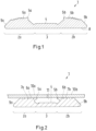
- a sealing sleeve 1 for a pipe clamp is shown in cross section, which is designed symmetrically, i.e. has mirror-inverted axial end regions 2a, 2b, between which a central region 3 with reduced material thickness is formed.
- a first sealing lips 5a, 5b and second sealing lips 6a, 6b are formed in each of the end regions 2a, 2b.
- the second sealing lips 6a, 6b are located further outward in the axial direction than the first sealing lips 5a, 5b.
- Adjacent to the second sealing lips 6a, 6b, further sealing lips 7a, 7b are arranged further outwards in the axial direction.
- the second sealing lips 6a, 6b and further sealing lips 7a, 7b essentially have a part-circular cross section and therefore act similarly to O-rings.
- the additional sealing lips 7a, 7b located axially further outward extend less far in the radial direction than the first sealing lip 5a, 5b and the second sealing lip 6a, 6b.
- a radial outside 8 of the sealing sleeve 1 is smooth.
- the sealing sleeve 1 therefore has a smooth cylindrical shape on the outside.
- the sealing sleeve 1 tapers on the inside at its axial outer edges 9a, 9b and can, for example, reach under an inwardly projecting metal strip of the pipe clamp, so that the sealing sleeve 1 can be held in a form-fitting manner within a pipe clamp.
- the middle region 3 has a reduced, constant material thickness compared to the axial end regions 2a, 2b, in which the sealing lips 5a, 5b, 6a, 6b, 7a, 7b are formed.
- This area essentially serves to clearly define a distance between the axial end areas 2a, 2b from one another.
- a band insert can be positioned between the axial end regions 2a, 2b on the inside 4, which covers the sealing sleeve 1 on the inside, i.e. on a side facing away from the pipe clamp.
- FIG 2 the sealing sleeve 1 is shown in cross section in a state braced against two pipe ends 10a, 10b. It can be seen that the sealing lips 5a, 5b have deformed axially and radially inwards. At a higher pressure within the pipe ends 10a, 10b, which then also prevails in a free space 11 radially within the central region 3, the first sealing lips 5a, 5b are pressed onto the surface of the pipe ends 10a, 10b. Increasing pressure increases the force on the first sealing lips 5a, 5b and thus also the sealing effect.
- the invention is not limited to one of the exemplary embodiments described, but can be modified in many ways.
- the shape of the second sealing lips and the further sealing lips can deviate from the part-circular cross-sectional shape shown and, for example, be pyramid-shaped.
- an additional sealing lip can also be provided which has the same cross-sectional geometry as the first sealing lip.
- the sealing sleeve according to the invention enables a secure seal even with rough surfaces of the pipe ends to be connected to one another.
- the sealing lips are at least partially very elastic, with a high sealing effect always being achieved due to the large number of sealing lips. Combined with A pipe clamp can be used to create very reliable pipe couplings.
Landscapes
- Engineering & Computer Science (AREA)
- General Engineering & Computer Science (AREA)
- Mechanical Engineering (AREA)
- Physics & Mathematics (AREA)
- Fluid Mechanics (AREA)
- Gasket Seals (AREA)
- Joints With Pressure Members (AREA)
- Joints With Sleeves (AREA)
Description
- Die Erfindung betrifft eine ringförmige Dichtungsmanschette für eine Rohrschelle, wobei die Dichtungsmanschette an einer Innenseite eine erste Dichtlippe mit einer ersten Querschnittsgeometrie und eine zweite Dichtlippe mit einer zweiten Querschnittsgeometrie aufweist. Ferner betrifft die Erfindung eine Rohrschelle mit einer derartigen Dichtungsmanschette.
- Rohrschellen finden beispielsweise in Form von Rohrkupplungen als kompaktes und zuverlässiges Mittel zur Verbindung glattendiger Rohre ihren Einsatz. Dabei können mit den Rohrschellen Kunststoff- und Metallrohre, aber insbesondere auch Edelstahlrohre oder Rohre aus Materialien wie Glas, Steinzeug oder Beton miteinander verbunden werden. In Verbindung mit einer Dichtungsmanschette wird dabei eine fluiddichte Verbindung erreicht, sodass mithilfe der über Rohrschellen verbundenen Rohre druckdichte Leitungen für feste, flüssige oder gasförmige Medien hergestellt werden können.
- Um auch bei höheren Drücken eine zuverlässige Abdichtung zu erreichen, ist es bekannt, eine Dichtungsmanschette an ihrer Innenseite mit zwei benachbarten Dichtlippen je Endbereich zu versehen. Diese beiden Dichtlippen sorgen sozusagen für eine doppelte Sicherheit und bewirken sowohl bei niedrigen als bei hohen Betriebsdrücken eine gute Dichtwirkung. Beim Spannen der Rohrschelle drücken sich dabei die Dichtlippen auch aufeinander, wobei durch eine entsprechende Geometrie an einer axialen Innenseite dafür gesorgt werden kann, dass mit zunehmendem Druck innerhalb des Rohres, der auch auf die Dichtlippen wirkt, auch die Dichtwirkung weiter zunimmt.
- Die bekannten Lösungen arbeiten an sich zufriedenstellend. Allerdings hat sich herausgestellt, dass insbesondere bei rauen Oberflächen der zu verbindenden Rohre Undichtigkeiten auftreten können. Ferner kann es auch bei sehr hohen Innendrücken zu Problemen kommen.
- Aus
WO 2009/045525 A2 undGB 2 211 255 A - Von
WO 97/43571 A1 EP 0 656 502 A2 ist jeweils eine Dichtungsmanschette beschrieben, bei der zwei Dichtlippen unterschiedlicher Geometrie benachbart zueinander angeordnet sind. Hierdurch deformieren die Dichtlippen beim Spannen einer mit der Dichtungsmanschette ausgestatteten Rohrschelle recht unabhängig voneinander. -
WO 88/07644 A1 - Der Erfindung liegt nun die Aufgabe zugrunde, eine Dichtungsmanschette für eine Rohrschelle und eine Rohrschelle bereitzustellen, die sowohl bei hohen als auch bei niedrigen Drücken eine hohe Dichtigkeit ermöglicht.
- Diese Aufgabe wird durch eine Dichtungsmanschette mit den Merkmalen des Anspruchs 1 sowie eine Rohrschelle mit den Merkmalen des Anspruchs 13 gelöst. Vorteilhafte Ausgestaltungen finden sich in den Unteransprüchen.
- Bei einer ringförmigen Dichtungsmanschette für eine Rohrschelle, wobei die Dichtungsmanschette an einer Innenseite in zumindest einem axialen Endbereich eine erste Dichtlippe mit einer ersten Querschnittsgeometrie und eine zweite Dichtlippe mit einer zweiten Querschnittsgeometrie aufweist, wobei die erste Querschnittsgeometrie und die zweite Querschnittsgeometrie unterschiedlich sind, wobei die erste Dichtlippe in axialer Richtung eine größere Erstreckung als in radialer Richtung aufweist und die zweite Dichtlippe in axialer Richtung eine gleiche oder geringere Erstreckung als in radialer Richtung aufweist, wobei die zweite Querschnittsgeometrie sich in radialer Richtung verjüngend, nämlich teilkreisförmig oder pyramidenförmig mit abgerundetem oder spitzen Kopfbereich ausgebildet ist, wodurch die zweite Dichtlippe wie ein O-Ring wirkt, ist erfindungsgemäß vorgesehen, dass die erste Dichtlippe aufgrund ihrer Querschnittsgeometrie steifer als die zweite Dichtlippe ist.
- Die Richtungsangaben axial bzw. radial beziehen sich dabei auf die Form der ringförmigen Dichtungsmanschette bzw. der damit verbundenen Rohre. Durch die entsprechende Ausgestaltung der unterschiedlichen Querschnittsgeometrien ergeben sich für die erste Dichtlippe und die zweite Dichtlippe unterschiedliche Eigenschaften. So ist die erste Dichtlippe aufgrund ihrer Querschnittsgeometrie steifer als die zweite Dichtlippe. Die erste Dichtlippe, die in axialer Richtung eine größere Erstreckung als in radialer Richtung aufweist, liegt an einer Oberfläche des Rohres relativ flächig an, bewirkt also eine großflächige Abdichtung mit relativ geringem Druck. Die zweite Dichtlippe liegt hingegen wie ein O-Ring nur über eine relativ kleine Kontaktfläche an der Oberfläche des Rohres und damit mit entsprechend hohem Druck an. Dabei lässt sich die zweite Dichtlippe einfacher verformen und kann sich somit gut an rauere Oberflächen anpassen. Durch die unterschiedlichen Querschnittsgeometrien der ersten und zweiten Dichtlippe wird so im Endbereich der Dichtungsmanschette eine sehr zuverlässige Abdichtung erreicht.
- Dabei ist besonders bevorzugt, dass die erste Dichtlippe von der zweiten Dichtlippe weg in axialer Richtung nach innen geneigt ist. Die ersten Dichtlippen sind so in Richtung eines Spalts zwischen zwei miteinander verbundenen Rohren geneigt. Durch diese Neigung axial nach innen wird die erste Dichtlippe mit steigendem Druck innerhalb des Rohres immer stärker an die Oberfläche des Rohres angedrückt, sodass mit steigendem Druck auch eine weiter verbesserte Abdichtung erhalten wird.
- Dabei ist insbesondere vorgesehen, dass die zweite Dichtlippe axial weiter außen angeordnet ist als die erste Dichtlippe. Die erste Dichtlippe ist somit direkt einem innerhalb des Rohres herrschenden Druck ausgesetzt und stellt somit die erste Dichtstufe dar, während die zweite Dichtlippe als zusätzliche Absicherung dient, selbst aber so einem verringerten Druck statthalten muss.
- In einer bevorzugten Ausgestaltung sind benachbart zur zweiten Dichtlippe weitere Dichtlippen mit gleicher Querschnittsgeometrie wie die zweite Dichtlippe angeordnet. Die weiteren Dichtlippen und die zweite Dichtlippe können so relativ dünn ausgebildet und dementsprechend elastisch sein, wobei durch die Mehrzahl an Dichtlippen eine mehrfache Abdichtung erhalten wird. Die Dichtlippen können sich dabei gut an eine raue Oberfläche anpassen und so auch dann eine sichere Abdichtung gewährleisten. Durch die weiteren Dichtlippen erhöht sich also die Zuverlässigkeit der erreichbaren Abdichtung weiter.
- Die zweite Querschnittsgeometrie ist teilkreisförmig oder pyramidenförmig mit abgerundetem oder spitzen Kopfbereich ausgebildet. Die zweiten Dichtlippen wirken damit wie O-Ringe und können sich gut an eine Oberfläche des Rohres anschmiegen. Gleichzeitig sind sie in der Lage, in radialer Richtung ausreichende Dichtkräfte aufzubauen, wohingegen sie in axialer Richtung relativ elastisch sind.
- Bevorzugterweise ist die Dichtungsmanschette symmetrisch aufgebaut, wobei an jedem axialen Endbereich eine Kombination von einer ersten Dichtlippe und einer zweiten Dichtlippe sowie gegebenenfalls weiterer Dichtlippen angeordnet ist. Dies ist insbesondere für Rohrschellen relevant, die als Rohrkupplungen zum Verbinden zweier Rohrenden eingesetzt werden. Somit ist jedem Rohrende eine Kombination von erster Dichtlippe und zweiter Dichtlippe sowie gegebenenfalls weiterer Dichtlippen zugeordnet und es wird eine sichere Abdichtung erhalten. Dabei ist vorzugsweise vorgesehen, dass die ersten Dichtlippen axial weiter innen liegen als die zweiten Dichtlippen und gegebenenfalls weiteren Dichtlippen. Die ersten Dichtlippen, die aufgrund ihrer Querschnittsgeometrie steifer sind als die zweite Dichtlippe und die weiteren Dichtlippen wirken somit als erste Abdichtung, die vom Rohrinnendruck beaufschlagt wird. Die zweiten Dichtlippen und weiteren Dichtlippen bewirken dann eine weitere nachgeschaltete Abdichtung.
- In einer bevorzugten Ausgestaltung erstrecken sich die axial weiter außen angeordneten weiteren Dichtlippen weniger weit radial nach innen als die ersten Dichtlippen. Beim Spannen der Rohrschelle legt sich somit zuerst die erste Dichtlippe an die Oberfläche des Rohres an und anschließend die zweite Dichtlippe und dann die weiteren Dichtlippen. Somit wird gewährleistet, dass beim Spannen der Rohrschelle vor allem die erste Dichtlippe mit ausreichendem Anpressdruck an die Rohroberfläche angedrückt wird, um eine ausreichende Dichtwirkung zu erzielen. Durch weiteres Spannen der Rohrschelle wird die Dichtungsmanschette dann derartig verformt, dass sich auch die anderen Dichtlippen an die Oberfläche des Rohres anlegen und eine zusätzliche Abdichtung erzielen. Die erste Dichtlippe und die zweite Dichtlippe liegen dann aber mit besonders hoher Kraft der Rohroberfläche an und bewirken eine sehr hohe Abdichtung.
- Dafür ist insbesondere vorgesehen, dass sich die erste Dichtlippe und die zweite Dichtlippe radial weiter nach innen erstrecken als zumindest eine der weiteren Dichtlippen. Insbesondere erstrecken sich die erste Dichtlippe und die zweite Dichtlippe dabei sogar gleich weit radial nach innen, kommen also gleichzeitig in Kontakt mit der Oberfläche des Rohres, sodass immer eine doppelte Abdichtung gewährleistet ist.
- In einer vorteilhaften Ausgestaltung weist die Dichtungsmanschette zwischen den ersten Dichtlippen einen mittleren Bereich mit konstanter Materialdicke auf, wobei das Dichtungselement in diesem Bereich dünner ist als im Bereich der Dichtlippen. Der mittlere Bereich dient im Wesentlichen dazu, die Bereiche mit den Dichtlippen miteinander zu verbinden und gegebenenfalls einen Spalt zwischen den Rohrenden zu überbrücken. Indem dieser Bereich dünner ausgebildet ist als der Bereich mit den Dichtlippen, ergibt sich eine Materialeinsparung. Dies führt so zu einem geringen Gewicht als auch zu geringen Herstellungskosten. Darüber hinaus ermöglicht die geringere Materialdicke, beispielsweise eine Bandeinlage an der radialen Innenseite im mittleren Bereich der Dichtungsmanschette anzuordnen. Diese kann dann z.B. als Versteifung und als Schutz vor mechanischer Belastung dienen. Außerdem kann die Bandeinlage bei Vakuumanwendungen einem Einziehen der elastischen Dichtmanschette in den Spalt zwischen den miteinander verbundenen Rohren entgegenwirken.
- Vorzugsweise ist eine radiale Außenseite der Dichtungsmanschette glatt ausgebildet. Die Dichtungsmanschette kann mit ihrer Außenseite damit vollflächig an einer Innenseite der Rohrschelle anliegen. Eine Außenkontur der Dichtungsmanschette entspricht somit einer Innenkontur der Rohrschelle.
- Vorteilhafterweise verjüngen sich axiale Außenkanten der Dichtungsmanschette in radialer Richtung. Die Außenkanten der Dichtungsmanschette können so beispielsweise unter umgebogene Kanten der Rohrschelle greifen, sodass die Dichtungsmanschette formschlüssig innerhalb der Rohrschelle gesichert wird. Ferner wird durch die Verjüngung eine gewisse Elastizität erreicht, was dazu führt, dass sich die axial äußeren Dichtlippen etwas leichter verformen lassen. Dabei kann durch den Winkel der Verjüngung eine Neigung optionaler Metallstreifen vorgegeben werden, die als Verankerungsringe dienen und eine Axialsicherung zweier miteinander verbundener Rohre bewirken.
- Die eingangs genannte Aufgabe wird auch durch eine Rohrschelle mit einer derartigen Dichtungsmanschette gelöst, wobei erfindungsgemäß vorgesehen ist, dass die Dichtungsmanschette an einer Innenseite der Rohrschelle angeordnet ist. Mit einer derartigen Rohrschelle lassen sich glatte Rohrenden zuverlässig und fluiddicht miteinander verbinden. Ferner kann eine derartige Rohrschelle als Reparaturschelle eingesetzt werden, indem sie eine Leckagestelle überdeckt.
- Vorzugsweise weist die Rohrschelle an der Innenseite mindestens einen mit radial nach innen ragenden Zähnen versehenen Metallstreifen auf, wobei insbesondere an beiden axialen Enden der Rohrschelle je ein derartiger Metallstreifen vorgesehen ist. Dieser Metallstreifen mit den nach innen ragenden Zähnen kann auch als Verankerungsring bezeichnet werden und bewirkt eine Axialsicherung der Rohrenden zueinander. Somit kann die Rohrschelle auch eine zugfeste Verbindung realisieren. Ohne derartige Metallstreifen würde die Rohrschelle nur eine reine Rohrkupplung mit dichtender Funktion darstellen, wobei eine Axialsicherung über ein zusätzliches Element realisiert werden müsste.
- Ferner kann auf einer Innenseite der Dichtungsmanschette eine Bandeinlage vorgesehen sein. Die Bandeinlage erstreckt sich nur im mittleren Bereich, also nur zwischen den jeweils in axialen Endbereichen ausgebildeten Dichtlippen. Sie schützt die Innenseite der Dichtungsmanschette.
- Die Erfindung wird im Folgenden anhand eines bevorzugten Ausführungsbeispiels in Verbindung mit den Zeichnungen näher beschrieben. Hierin zeigen:
- In
Figur 1 ist im Querschnitt eine Dichtungsmanschette 1 für eine Rohrschelle dargestellt, die symmetrisch ausgebildet ist, also spiegelbildlich aufgebaute axiale Endbereiche 2a, 2b aufweist, zwischen denen ein mittlerer Bereich 3 mit verringerter Materialdicke ausgebildet ist. An einer Innenseite 4 der Dichtungsmanschette 1 sind in jedem der Endbereiche 2a, 2b je eine erste Dichtlippen 5a, 5b und zweite Dichtlippen 6a, 6b ausgebildet. Die zweiten Dichtlippen 6a, 6b befinden sich dabei in axialer Richtung weiter außen als die ersten Dichtlippen 5a, 5b. Benachbart zu den zweiten Dichtlippen 6a, 6b sind in axialer Richtung weiter nach außen weitere Dichtlippen 7a, 7b angeordnet. - Die ersten Dichtlippen 5a, 5b weisen eine erste Querschnittsgeometrie auf und erstrecken sich in axialer Richtung weiter als in radialer Richtung. Dabei sind sie von der zweiten Dichtlippe 6a, 6b jeweils weggeneigt, also in axialer Richtung nach innen. Die zweiten Dichtlippen 6a, 6b sowie die weiteren Dichtlippen 7a, 7b weisen eine zweite Querschnittsgeometrie auf und erstrecken sich in radialer Richtung weiter oder genauso weit wie in axialer Richtung. Die zweiten
- Figur 1
- einen Querschnitt durch eine Dichtungsmanschette im unbelasteten Zustand und
- Figur 2
- einen Querschnitt durch eine Dichtungsmanschette im belasteten Zustand.
- Die zweiten Dichtlippen 6a, 6b und weiteren Dichtlippen 7a, 7b weisen im Wesentlichen einen teilkreisförmigen Querschnitt auf und wirken dementsprechend ähnliche wie O-Ringe. Dabei erstrecken sich die axial weiter außen liegenden weiteren Dichtlippen 7a, 7b weniger weit in radialer Richtung als die erste Dichtlippe 5a, 5b und die zweite Dichtlippe 6a, 6b. Beim Spannen der Dichtungsmanschette 1 mit einer Rohrschelle um glatte Rohrenden legen sich also zunächst die ersten Dichtlippen 5a, 5b und die zweiten Dichtlippen 6a, 6b an eine Oberfläche der Rohre an und anschließend die weiteren Dichtlippen 7a, 7b. Die ersten Dichtlippen 5a, 5b und die zweiten Dichtlippen 6a, 6b werden dementsprechend mit relativ großer Kontaktkraft an die Oberfläche der Rohre angedrückt und bewirken so eine besonders gute Abdichtung.
- Eine radiale Außenseite 8 der Dichtungsmanschette 1 ist glatt ausgebildet. Die Dichtungsmanschette 1 weist also außen eine glatte Zylinderform auf. Dabei verjüngt sich die Dichtungsmanschette 1 innenseitig an ihren axialen äußeren Kanten 9a, 9b und kann so beispielsweise einen nach innen ragenden Metallstreifen der Rohrschelle untergreifen, sodass die Dichtungsmanschette 1 formschlüssig innerhalb einer Rohrschelle gehalten werden kann.
- Der mittlere Bereich 3 weist gegenüber den axialen Endbereichen 2a, 2b, in denen die Dichtlippen 5a, 5b, 6a, 6b, 7a, 7b ausgebildet sind, eine verringerte, konstante Materialstärke auf. Dieser Bereich dient im Wesentlichen dazu, einen Abstand der axialen Endbereiche 2a, 2b zueinander eindeutig zu definieren. Ferner kann durch die geringere Materialstärke zwischen den axialen Endbereichen 2a, 2b auf der Innenseite 4 eine Bandeinlage positioniert werden, die die Dichtungsmanschette 1 nach innen, also einer von der Rohrschelle abgewandten Seite, abdeckt.
- In
Figur 2 ist die Dichtungsmanschette 1 in einem gegenüber zwei Rohrenden 10a, 10b verspannten Zustand im Querschnitt dargestellt. Es ist zu erkennen, dass sich die Dichtlippen 5a, 5b axial und radial nach innen verformt haben. Bei einem höheren Druck innerhalb der Rohrenden 10a, 10b, der dann auch in einem Freiraum 11 radial innerhalb des mittleren Bereichs 3 herrscht, werden die ersten Dichtlippen 5a, 5b auf die Oberfläche der Rohrenden 10a, 10b gedrückt. Durch steigenden Druck erhöht sich dabei die Kraft auf die ersten Dichtlippen 5a, 5b und damit auch die Dichtwirkung. - Durch das Verspannen der Dichtungsmanschette 1 sind Freiräume, die im unbelasteten Zustand der Dichtungsmanschette 1 zwischen den zweiten Dichtlippen 6a, 6b und den weiteren Dichtlippen 7a, 7b sowie auch der ersten Dichtlippen 5a, 5b ausgebildet sind, teilweise oder vollständig verschwunden. Alle Dichtlippen 5a, 5b, 6a, 6b, 7a, 7b liegen somit unter Spannung an den Rohrenden 10a, 10b an und bewirken eine sehr gute Abdichtung. Dabei kann durch die Vielzahl der relativ elastischen Dichtlippen auch bei einer rauen Oberfläche der Rohrenden 10a, 10b eine gute Abdichtung gewährleistet werden.
- Die Erfindung ist nicht auf eines der beschriebenen Ausführungsbeispiele beschränkt, sondern in vielfältiger Weise abwandelbar. So kann beispielsweise die Form der zweiten Dichtlippen und der weiteren Dichtlippen von der gezeigten, teilkreisförmigen Querschnittsform abweichen und z.B. pyramidenförmig ausgebildet sein. Auch kann gegebenenfalls eine zusätzliche Dichtlippe vorgesehen werden, die die gleiche Querschnittsgeometrie wie die erste Dichtlippe hat. Ferner ist es möglich, dass sich alle Dichtlippen radial gleich weit nach innen erstrecken.
- Die erfindungsgemäße Dichtungsmanschette ermöglicht eine sichere Abdichtung auch bei rauen Oberflächen der miteinander zu verbindenden Rohrenden. Dabei sind die Dichtlippen zumindest teilweise sehr elastisch, wobei durch die Vielzahl der Dichtlippen immer eine hohe Dichtwirkung erzielt wird. In Verbindung mit einer Rohrschelle können so sehr zuverlässige Rohrkupplungen realisiert werden.
-
1 Dichtungsmanschette 7a weitere Dichtlippen 2a axiale Endbereiche 7b weitere Dichtlippen 2b axiale Endbereiche 8 Außenseite 3 mittlerer Bereich 9a axiale Außenkanten 4 Innenseite 9b axiale Außenkanten 5a erste Dichtlippen 10a Rohrenden 5b erste Dichtlippen 10b Rohrenden 6a zweite Dichtlippen 11 Freiraum 6b zweite Dichtlippen
Claims (15)
- Ringförmige Dichtungsmanschette (1) für eine Rohrschelle, wobei die Dichtungsmanschette (1) an einer Innenseite (4) eine erste Dichtlippe (5a, 5b) mit einer ersten Querschnittsgeometrie und eine zweite Dichtlippe (6a, 6b) mit einer zweiten Querschnittsgeometrie aufweist, wobei die erste Querschnittsgeometrie und die zweite Querschnittsgeometrie unterschiedlich sind, wobei die erste Dichtlippe (5a, 5b) in axialer Richtung eine größere Erstreckung als in radialer Richtung aufweist und die zweite Dichtlippe (6a, 6b) in axialer Richtung eine gleiche oder geringere Erstreckung als in radialer Richtung aufweist, wobei die zweite Querschnittsgeometrie sich in radialer Richtung verjüngend, nämlich teilkreisförmig oder pyramidenförmig mit abgerundetem oder spitzen Kopfbereich ausgebildet ist, wodurch die zweite Dichtlippe (6a, 6b) wie ein O-Ring wirkt, dadurch gekennzeichnet, dass die erste Dichtlippe (5a, 5b) aufgrund ihrer Querschnittsgeometrie steifer als die zweite Dichtlippe (6a, 6b) ist.
- Dichtungsmanschette nach Anspruch 1, dadurch gekennzeichnet, dass die erste Dichtlippe (5a, 5b) von der zweiten Dichtlippe (6a, 6b) weg in axialer Richtung nach innen geneigt ist.
- Dichtungsmanschette nach Anspruch 1 oder 2, dadurch gekennzeichnet, dass die zweite Dichtlippe (6a, 6b) axial weiter außen angeordnet ist als die erste Dichtlippe (5a, 5b).
- Dichtungsmanschette nach einem der vorhergehenden Ansprüche, dadurch gekennzeichnet, dass sie benachbart zur zweiten Dichtlippe (6a, 6b) weitere Dichtlippen (7a, 7b) mit gleicher Querschnittsgeometrie wie die zweite Dichtlippe (6a, 6b) aufweist.
- Dichtungsmanschette nach Anspruch 4, dadurch gekennzeichnet, dass die zweite Dichtlippe (6a, 6b) und die weiteren Dichtlippen (7a, 7b) wenig oder kaum geneigt und in axialer Richtung flexibler als die erste Dichtlippe (5a, 5b) sind.
- Dichtungsmanschette nach einem der Ansprüche 4 oder 5, dadurch gekennzeichnet, dass sich axial weiter außen angeordnete weitere Dichtlippen (7a, 7b) weniger weit radial nach innen erstrecken als die erste Dichtlippe (5a, 5b).
- Dichtungsmanschette nach einem der Ansprüche 4 bis 6, dadurch gekennzeichnet, dass sich die erste Dichtlippe (5a, 5b) und die zweite Dichtlippe (6a, 6b) radial weiter nach innen erstrecken als zumindest eine der weiteren Dichtlippen (7a, 7b).
- Dichtungsmanschette nach einem der vorhergehenden Ansprüche, dadurch gekennzeichnet, dass sie symmetrisch aufgebaut ist, wobei an jedem axialen Endbereich (2a, 2b) eine Kombination von einer ersten Dichtlippe (5a, 5b) und einer zweiten Dichtlippe (6a, 6b) und gegebenenfalls weiterer Dichtlippen (7a, 7b) angeordnet ist.
- Dichtungsmanschette nach Anspruch 8, dadurch gekennzeichnet, dass die ersten Dichtlippen (5a, 5b) axial weiter innen liegen als die zweiten Dichtlippen (6a, 6b) und gegebenenfalls weitere Dichtlippen (7a, 7b).
- Dichtungsmanschette nach einem der Ansprüche 8 oder 9, dadurch gekennzeichnet, dass die Dichtungsmanschette (1) zwischen den ersten Dichtlippen (5a, 5b) einen mittleren Bereich (3) mit konstanter Materialdicke aufweist, wobei die Dichtungsmanschette (1) in diesem mittleren Bereich (3) dünner ist als im Bereich der Dichtlippen (5a, 5b, 6a, 6b, 7a, 7b).
- Dichtungsmanschette nach einem der vorhergehenden Ansprüche, dadurch gekennzeichnet, dass eine radiale Außenseite (8) der Dichtungsmanschette (1) glatt ausgebildet ist.
- Dichtungsmanschette nach einem der vorhergehenden Ansprüche, dadurch gekennzeichnet, dass sich axiale Außenkanten (9a, 9b) der Dichtungsmanschette (1) in radialer Richtung verjüngen.
- Rohrschelle mit einer Dichtungsmanschette (1) nach einem der vorhergehenden Ansprüche, dadurch gekennzeichnet, dass die Dichtungsmanschette (1) an einer Innenseite der Rohrschelle angeordnet ist.
- Rohrschelle nach Anspruch 13, dadurch gekennzeichnet, dass an der Innenseite der Rohrschelle mindestens ein mit radial nach innen ragenden Zähnen versehener Metallstreifen angeordnet ist.
- Rohrschelle nach einem der Ansprüche 13 oder 14 in Kombination mit Anspruch 8, dadurch gekennzeichnet, dass auf der Innenseite (4) der Dichtungsmanschette (1) eine Bandeinlage vorgesehen ist, die sich nur im mittleren Bereich zwischen den jeweils in den axialen Endbereichen (2a, 2b) ausgebildeten Dichtlippen (5a, 5b, 6a, 6b) erstreckt.
Applications Claiming Priority (2)
| Application Number | Priority Date | Filing Date | Title |
|---|---|---|---|
| DE102017113789.0A DE102017113789A1 (de) | 2017-06-21 | 2017-06-21 | Dichtungsmanschette für eine Rohrschelle und Rohrschelle mit einer derartigen Dichtungsmanschette |
| PCT/EP2018/065944 WO2018234178A1 (de) | 2017-06-21 | 2018-06-15 | Dichtungsmanschette für eine rohrschelle und rohrschelle mit einer derartigen dichtungsmanschette |
Publications (2)
| Publication Number | Publication Date |
|---|---|
| EP3642523A1 EP3642523A1 (de) | 2020-04-29 |
| EP3642523B1 true EP3642523B1 (de) | 2023-12-27 |
Family
ID=62636217
Family Applications (1)
| Application Number | Title | Priority Date | Filing Date |
|---|---|---|---|
| EP18732050.2A Active EP3642523B1 (de) | 2017-06-21 | 2018-06-15 | Dichtungsmanschette für eine rohrschelle und rohrschelle mit einer derartigen dichtungsmanschette |
Country Status (6)
| Country | Link |
|---|---|
| EP (1) | EP3642523B1 (de) |
| JP (1) | JP7049372B2 (de) |
| KR (1) | KR20200016966A (de) |
| CN (1) | CN110770487A (de) |
| DE (1) | DE102017113789A1 (de) |
| WO (1) | WO2018234178A1 (de) |
Family Cites Families (13)
| Publication number | Priority date | Publication date | Assignee | Title |
|---|---|---|---|---|
| US1930194A (en) * | 1930-06-28 | 1933-10-10 | Stephen V Dillon | Pipe coupling |
| JPS52150815U (de) * | 1976-05-13 | 1977-11-15 | ||
| GB8707057D0 (en) * | 1987-03-25 | 1987-04-29 | Taylor Kerr Couplings Ltd | Flexible pipe couplings |
| GB8724335D0 (en) * | 1987-10-16 | 1987-11-18 | Victaulic Plc | Pipe joint & coupling |
| CH685308A5 (de) * | 1993-12-02 | 1995-05-31 | Peter Ilesic | Dichtvorrichtung zum Abdichten von Rohrleitungen. |
| DE29608499U1 (de) * | 1996-05-10 | 1996-08-08 | Ilešič, Peter, Maribor | Rohrkupplung |
| DE20014142U1 (de) * | 2000-04-22 | 2001-02-22 | Wantoch, Manfred, 44866 Bochum | Rohrkupplung |
| JP4654181B2 (ja) * | 2003-04-25 | 2011-03-16 | ビクトリック カンパニー | パイプ連結器のガスケット及び、これが組み込まれたパイプ連結器 |
| JP2005090605A (ja) * | 2003-09-16 | 2005-04-07 | Riken Corp | 管継手 |
| JP2007113781A (ja) * | 2005-09-20 | 2007-05-10 | Inter Kogyo:Kk | 管継手 |
| CA2705351C (en) * | 2007-10-03 | 2014-01-21 | Anvil International, Lp | Coupling gaskets and associated methods |
| ES2555497T3 (es) * | 2009-10-27 | 2016-01-04 | Tyco Fire Products Lp | Sistemas y métodos para acoplamientos de cañerías |
| CN204805778U (zh) * | 2015-07-10 | 2015-11-25 | 郭文星 | 管道接头 |
-
2017
- 2017-06-21 DE DE102017113789.0A patent/DE102017113789A1/de not_active Withdrawn
-
2018
- 2018-06-15 EP EP18732050.2A patent/EP3642523B1/de active Active
- 2018-06-15 WO PCT/EP2018/065944 patent/WO2018234178A1/de not_active Ceased
- 2018-06-15 KR KR1020207000764A patent/KR20200016966A/ko not_active Ceased
- 2018-06-15 CN CN201880041499.7A patent/CN110770487A/zh active Pending
- 2018-06-15 JP JP2019571246A patent/JP7049372B2/ja active Active
Also Published As
| Publication number | Publication date |
|---|---|
| JP7049372B2 (ja) | 2022-04-06 |
| WO2018234178A1 (de) | 2018-12-27 |
| CN110770487A (zh) | 2020-02-07 |
| DE102017113789A1 (de) | 2018-12-27 |
| EP3642523A1 (de) | 2020-04-29 |
| JP2020524771A (ja) | 2020-08-20 |
| KR20200016966A (ko) | 2020-02-17 |
Similar Documents
| Publication | Publication Date | Title |
|---|---|---|
| DE10119534B4 (de) | Metallische Dichtung | |
| EP0186727B1 (de) | Rohrverbindung | |
| DE102009007303B4 (de) | Fitting für dickwandige Rohre | |
| EP2140188B1 (de) | Ventil zum trennen von produktmedien in rohrleitungen einer produktführenden anlage | |
| EP2044359B1 (de) | Hülse und kombination von hülse mit presswerkzeug | |
| EP1564469A1 (de) | Fitting für eine Pressverbindung | |
| EP3978751B1 (de) | Verbundmembran für membranpumpen | |
| DE2714963C3 (de) | Elastisches Rohrverbindungsstück | |
| EP0223185B1 (de) | Rohrkupplung | |
| DE202007010592U1 (de) | Anordnung zur Befestigung einer Leitung mit einem profilierten Außendurchmesser | |
| EP3364086B1 (de) | Verbindungsanordnung zum anschluss einer rohrleitung | |
| DE102011119513A1 (de) | Rohrverbindung zur fluiddichten Anbindung von Komponenten einer Klimaanlage | |
| EP3073166B1 (de) | Flanschverbindung | |
| DE60214775T2 (de) | Flanschglied mit einem ersten flanschende, das in einer radialrichtung mit einer konkaven endfläche ausgeführt ist, und einer flanschgliederumfassenden flanschverbindung | |
| EP2459905B1 (de) | Dichtring und anordnung mit einem dichtring | |
| DE112017007969T5 (de) | Kolbendichtungsbaugruppe für ein Kupplungsausrücksystem sowie Kupplungsausrücksystem | |
| EP3464963A1 (de) | Nutringdichtung und verfahren zum herstellen derselben | |
| EP3642523B1 (de) | Dichtungsmanschette für eine rohrschelle und rohrschelle mit einer derartigen dichtungsmanschette | |
| DE19635053C2 (de) | Schlaucharmatur für Druckschläuche | |
| DE202013007855U1 (de) | Dichteinrichtung für Rohrverbindungen | |
| DE4124221C2 (de) | Dichtring | |
| DE102020108722A1 (de) | Kammprofildichtring und Flanschverbindung | |
| DE1937399C3 (de) | Vorrichtung zum abgedichteten Aneinanderkuppeln von fließfähige Medien führenden Elementen, beispielsweise Leitungsrohren | |
| EP2189686B1 (de) | Dichtungselement | |
| EP3842671B1 (de) | Wellendichtung, insbesondere radialwellendichtung, mit wenigstens einem dichtelement |
Legal Events
| Date | Code | Title | Description |
|---|---|---|---|
| STAA | Information on the status of an ep patent application or granted ep patent |
Free format text: STATUS: UNKNOWN |
|
| STAA | Information on the status of an ep patent application or granted ep patent |
Free format text: STATUS: THE INTERNATIONAL PUBLICATION HAS BEEN MADE |
|
| PUAI | Public reference made under article 153(3) epc to a published international application that has entered the european phase |
Free format text: ORIGINAL CODE: 0009012 |
|
| STAA | Information on the status of an ep patent application or granted ep patent |
Free format text: STATUS: REQUEST FOR EXAMINATION WAS MADE |
|
| 17P | Request for examination filed |
Effective date: 20200113 |
|
| AK | Designated contracting states |
Kind code of ref document: A1 Designated state(s): AL AT BE BG CH CY CZ DE DK EE ES FI FR GB GR HR HU IE IS IT LI LT LU LV MC MK MT NL NO PL PT RO RS SE SI SK SM TR |
|
| AX | Request for extension of the european patent |
Extension state: BA ME |
|
| DAV | Request for validation of the european patent (deleted) | ||
| DAX | Request for extension of the european patent (deleted) | ||
| STAA | Information on the status of an ep patent application or granted ep patent |
Free format text: STATUS: EXAMINATION IS IN PROGRESS |
|
| 17Q | First examination report despatched |
Effective date: 20220301 |
|
| GRAP | Despatch of communication of intention to grant a patent |
Free format text: ORIGINAL CODE: EPIDOSNIGR1 |
|
| STAA | Information on the status of an ep patent application or granted ep patent |
Free format text: STATUS: GRANT OF PATENT IS INTENDED |
|
| INTG | Intention to grant announced |
Effective date: 20230802 |
|
| GRAS | Grant fee paid |
Free format text: ORIGINAL CODE: EPIDOSNIGR3 |
|
| GRAA | (expected) grant |
Free format text: ORIGINAL CODE: 0009210 |
|
| STAA | Information on the status of an ep patent application or granted ep patent |
Free format text: STATUS: THE PATENT HAS BEEN GRANTED |
|
| AK | Designated contracting states |
Kind code of ref document: B1 Designated state(s): AL AT BE BG CH CY CZ DE DK EE ES FI FR GB GR HR HU IE IS IT LI LT LU LV MC MK MT NL NO PL PT RO RS SE SI SK SM TR |
|
| REG | Reference to a national code |
Ref country code: GB Ref legal event code: FG4D Free format text: NOT ENGLISH |
|
| REG | Reference to a national code |
Ref country code: CH Ref legal event code: EP |
|
| REG | Reference to a national code |
Ref country code: DE Ref legal event code: R096 Ref document number: 502018013869 Country of ref document: DE |
|
| REG | Reference to a national code |
Ref country code: IE Ref legal event code: FG4D Free format text: LANGUAGE OF EP DOCUMENT: GERMAN |
|
| PG25 | Lapsed in a contracting state [announced via postgrant information from national office to epo] |
Ref country code: GR Free format text: LAPSE BECAUSE OF FAILURE TO SUBMIT A TRANSLATION OF THE DESCRIPTION OR TO PAY THE FEE WITHIN THE PRESCRIBED TIME-LIMIT Effective date: 20240328 |
|
| REG | Reference to a national code |
Ref country code: LT Ref legal event code: MG9D |
|
| PG25 | Lapsed in a contracting state [announced via postgrant information from national office to epo] |
Ref country code: LT Free format text: LAPSE BECAUSE OF FAILURE TO SUBMIT A TRANSLATION OF THE DESCRIPTION OR TO PAY THE FEE WITHIN THE PRESCRIBED TIME-LIMIT Effective date: 20231227 |
|
| PG25 | Lapsed in a contracting state [announced via postgrant information from national office to epo] |
Ref country code: ES Free format text: LAPSE BECAUSE OF FAILURE TO SUBMIT A TRANSLATION OF THE DESCRIPTION OR TO PAY THE FEE WITHIN THE PRESCRIBED TIME-LIMIT Effective date: 20231227 |
|
| PG25 | Lapsed in a contracting state [announced via postgrant information from national office to epo] |
Ref country code: LT Free format text: LAPSE BECAUSE OF FAILURE TO SUBMIT A TRANSLATION OF THE DESCRIPTION OR TO PAY THE FEE WITHIN THE PRESCRIBED TIME-LIMIT Effective date: 20231227 Ref country code: GR Free format text: LAPSE BECAUSE OF FAILURE TO SUBMIT A TRANSLATION OF THE DESCRIPTION OR TO PAY THE FEE WITHIN THE PRESCRIBED TIME-LIMIT Effective date: 20240328 Ref country code: FI Free format text: LAPSE BECAUSE OF FAILURE TO SUBMIT A TRANSLATION OF THE DESCRIPTION OR TO PAY THE FEE WITHIN THE PRESCRIBED TIME-LIMIT Effective date: 20231227 Ref country code: ES Free format text: LAPSE BECAUSE OF FAILURE TO SUBMIT A TRANSLATION OF THE DESCRIPTION OR TO PAY THE FEE WITHIN THE PRESCRIBED TIME-LIMIT Effective date: 20231227 Ref country code: BG Free format text: LAPSE BECAUSE OF FAILURE TO SUBMIT A TRANSLATION OF THE DESCRIPTION OR TO PAY THE FEE WITHIN THE PRESCRIBED TIME-LIMIT Effective date: 20240327 |
|
| REG | Reference to a national code |
Ref country code: NL Ref legal event code: MP Effective date: 20231227 |
|
| PG25 | Lapsed in a contracting state [announced via postgrant information from national office to epo] |
Ref country code: NL Free format text: LAPSE BECAUSE OF FAILURE TO SUBMIT A TRANSLATION OF THE DESCRIPTION OR TO PAY THE FEE WITHIN THE PRESCRIBED TIME-LIMIT Effective date: 20231227 |
|
| PG25 | Lapsed in a contracting state [announced via postgrant information from national office to epo] |
Ref country code: SE Free format text: LAPSE BECAUSE OF FAILURE TO SUBMIT A TRANSLATION OF THE DESCRIPTION OR TO PAY THE FEE WITHIN THE PRESCRIBED TIME-LIMIT Effective date: 20231227 Ref country code: RS Free format text: LAPSE BECAUSE OF FAILURE TO SUBMIT A TRANSLATION OF THE DESCRIPTION OR TO PAY THE FEE WITHIN THE PRESCRIBED TIME-LIMIT Effective date: 20231227 Ref country code: NO Free format text: LAPSE BECAUSE OF FAILURE TO SUBMIT A TRANSLATION OF THE DESCRIPTION OR TO PAY THE FEE WITHIN THE PRESCRIBED TIME-LIMIT Effective date: 20240327 Ref country code: NL Free format text: LAPSE BECAUSE OF FAILURE TO SUBMIT A TRANSLATION OF THE DESCRIPTION OR TO PAY THE FEE WITHIN THE PRESCRIBED TIME-LIMIT Effective date: 20231227 Ref country code: LV Free format text: LAPSE BECAUSE OF FAILURE TO SUBMIT A TRANSLATION OF THE DESCRIPTION OR TO PAY THE FEE WITHIN THE PRESCRIBED TIME-LIMIT Effective date: 20231227 Ref country code: HR Free format text: LAPSE BECAUSE OF FAILURE TO SUBMIT A TRANSLATION OF THE DESCRIPTION OR TO PAY THE FEE WITHIN THE PRESCRIBED TIME-LIMIT Effective date: 20231227 |
|
| PG25 | Lapsed in a contracting state [announced via postgrant information from national office to epo] |
Ref country code: IS Free format text: LAPSE BECAUSE OF FAILURE TO SUBMIT A TRANSLATION OF THE DESCRIPTION OR TO PAY THE FEE WITHIN THE PRESCRIBED TIME-LIMIT Effective date: 20240427 |
|
| PG25 | Lapsed in a contracting state [announced via postgrant information from national office to epo] |
Ref country code: CZ Free format text: LAPSE BECAUSE OF FAILURE TO SUBMIT A TRANSLATION OF THE DESCRIPTION OR TO PAY THE FEE WITHIN THE PRESCRIBED TIME-LIMIT Effective date: 20231227 |
|
| PG25 | Lapsed in a contracting state [announced via postgrant information from national office to epo] |
Ref country code: SK Free format text: LAPSE BECAUSE OF FAILURE TO SUBMIT A TRANSLATION OF THE DESCRIPTION OR TO PAY THE FEE WITHIN THE PRESCRIBED TIME-LIMIT Effective date: 20231227 |
|
| PG25 | Lapsed in a contracting state [announced via postgrant information from national office to epo] |
Ref country code: SM Free format text: LAPSE BECAUSE OF FAILURE TO SUBMIT A TRANSLATION OF THE DESCRIPTION OR TO PAY THE FEE WITHIN THE PRESCRIBED TIME-LIMIT Effective date: 20231227 Ref country code: SK Free format text: LAPSE BECAUSE OF FAILURE TO SUBMIT A TRANSLATION OF THE DESCRIPTION OR TO PAY THE FEE WITHIN THE PRESCRIBED TIME-LIMIT Effective date: 20231227 Ref country code: RO Free format text: LAPSE BECAUSE OF FAILURE TO SUBMIT A TRANSLATION OF THE DESCRIPTION OR TO PAY THE FEE WITHIN THE PRESCRIBED TIME-LIMIT Effective date: 20231227 Ref country code: IT Free format text: LAPSE BECAUSE OF FAILURE TO SUBMIT A TRANSLATION OF THE DESCRIPTION OR TO PAY THE FEE WITHIN THE PRESCRIBED TIME-LIMIT Effective date: 20231227 Ref country code: IS Free format text: LAPSE BECAUSE OF FAILURE TO SUBMIT A TRANSLATION OF THE DESCRIPTION OR TO PAY THE FEE WITHIN THE PRESCRIBED TIME-LIMIT Effective date: 20240427 Ref country code: EE Free format text: LAPSE BECAUSE OF FAILURE TO SUBMIT A TRANSLATION OF THE DESCRIPTION OR TO PAY THE FEE WITHIN THE PRESCRIBED TIME-LIMIT Effective date: 20231227 Ref country code: CZ Free format text: LAPSE BECAUSE OF FAILURE TO SUBMIT A TRANSLATION OF THE DESCRIPTION OR TO PAY THE FEE WITHIN THE PRESCRIBED TIME-LIMIT Effective date: 20231227 |
|
| PG25 | Lapsed in a contracting state [announced via postgrant information from national office to epo] |
Ref country code: PL Free format text: LAPSE BECAUSE OF FAILURE TO SUBMIT A TRANSLATION OF THE DESCRIPTION OR TO PAY THE FEE WITHIN THE PRESCRIBED TIME-LIMIT Effective date: 20231227 Ref country code: PT Free format text: LAPSE BECAUSE OF FAILURE TO SUBMIT A TRANSLATION OF THE DESCRIPTION OR TO PAY THE FEE WITHIN THE PRESCRIBED TIME-LIMIT Effective date: 20240429 |
|
| PG25 | Lapsed in a contracting state [announced via postgrant information from national office to epo] |
Ref country code: PT Free format text: LAPSE BECAUSE OF FAILURE TO SUBMIT A TRANSLATION OF THE DESCRIPTION OR TO PAY THE FEE WITHIN THE PRESCRIBED TIME-LIMIT Effective date: 20240429 Ref country code: PL Free format text: LAPSE BECAUSE OF FAILURE TO SUBMIT A TRANSLATION OF THE DESCRIPTION OR TO PAY THE FEE WITHIN THE PRESCRIBED TIME-LIMIT Effective date: 20231227 |
|
| REG | Reference to a national code |
Ref country code: DE Ref legal event code: R097 Ref document number: 502018013869 Country of ref document: DE |
|
| PG25 | Lapsed in a contracting state [announced via postgrant information from national office to epo] |
Ref country code: DK Free format text: LAPSE BECAUSE OF FAILURE TO SUBMIT A TRANSLATION OF THE DESCRIPTION OR TO PAY THE FEE WITHIN THE PRESCRIBED TIME-LIMIT Effective date: 20231227 |
|
| PG25 | Lapsed in a contracting state [announced via postgrant information from national office to epo] |
Ref country code: DK Free format text: LAPSE BECAUSE OF FAILURE TO SUBMIT A TRANSLATION OF THE DESCRIPTION OR TO PAY THE FEE WITHIN THE PRESCRIBED TIME-LIMIT Effective date: 20231227 |
|
| PLBE | No opposition filed within time limit |
Free format text: ORIGINAL CODE: 0009261 |
|
| STAA | Information on the status of an ep patent application or granted ep patent |
Free format text: STATUS: NO OPPOSITION FILED WITHIN TIME LIMIT |
|
| 26N | No opposition filed |
Effective date: 20240930 |
|
| PG25 | Lapsed in a contracting state [announced via postgrant information from national office to epo] |
Ref country code: MC Free format text: LAPSE BECAUSE OF FAILURE TO SUBMIT A TRANSLATION OF THE DESCRIPTION OR TO PAY THE FEE WITHIN THE PRESCRIBED TIME-LIMIT Effective date: 20231227 |
|
| REG | Reference to a national code |
Ref country code: CH Ref legal event code: PL |
|
| PG25 | Lapsed in a contracting state [announced via postgrant information from national office to epo] |
Ref country code: LU Free format text: LAPSE BECAUSE OF NON-PAYMENT OF DUE FEES Effective date: 20240615 |
|
| PG25 | Lapsed in a contracting state [announced via postgrant information from national office to epo] |
Ref country code: IE Free format text: LAPSE BECAUSE OF NON-PAYMENT OF DUE FEES Effective date: 20240615 |
|
| PG25 | Lapsed in a contracting state [announced via postgrant information from national office to epo] |
Ref country code: SI Free format text: LAPSE BECAUSE OF FAILURE TO SUBMIT A TRANSLATION OF THE DESCRIPTION OR TO PAY THE FEE WITHIN THE PRESCRIBED TIME-LIMIT Effective date: 20231227 Ref country code: BE Free format text: LAPSE BECAUSE OF NON-PAYMENT OF DUE FEES Effective date: 20240630 Ref country code: CH Free format text: LAPSE BECAUSE OF NON-PAYMENT OF DUE FEES Effective date: 20240630 |
|
| REG | Reference to a national code |
Ref country code: BE Ref legal event code: MM Effective date: 20240630 |
|
| PGFP | Annual fee paid to national office [announced via postgrant information from national office to epo] |
Ref country code: DE Payment date: 20250627 Year of fee payment: 8 |
|
| PGFP | Annual fee paid to national office [announced via postgrant information from national office to epo] |
Ref country code: GB Payment date: 20250627 Year of fee payment: 8 |
|
| PGFP | Annual fee paid to national office [announced via postgrant information from national office to epo] |
Ref country code: FR Payment date: 20250625 Year of fee payment: 8 |
|
| REG | Reference to a national code |
Ref country code: AT Ref legal event code: MM01 Ref document number: 1644818 Country of ref document: AT Kind code of ref document: T Effective date: 20240615 |
|
| PG25 | Lapsed in a contracting state [announced via postgrant information from national office to epo] |
Ref country code: AT Free format text: LAPSE BECAUSE OF NON-PAYMENT OF DUE FEES Effective date: 20240615 |
|
| PG25 | Lapsed in a contracting state [announced via postgrant information from national office to epo] |
Ref country code: CY Free format text: LAPSE BECAUSE OF FAILURE TO SUBMIT A TRANSLATION OF THE DESCRIPTION OR TO PAY THE FEE WITHIN THE PRESCRIBED TIME-LIMIT; INVALID AB INITIO Effective date: 20180615 |
|
| PG25 | Lapsed in a contracting state [announced via postgrant information from national office to epo] |
Ref country code: HU Free format text: LAPSE BECAUSE OF FAILURE TO SUBMIT A TRANSLATION OF THE DESCRIPTION OR TO PAY THE FEE WITHIN THE PRESCRIBED TIME-LIMIT; INVALID AB INITIO Effective date: 20180615 |