EP3642523B1 - Manchon d'étanchéité pour un collier de serrage et collier de serrage comprenant un manchon d'étanchéité de ce type - Google Patents
Manchon d'étanchéité pour un collier de serrage et collier de serrage comprenant un manchon d'étanchéité de ce type Download PDFInfo
- Publication number
- EP3642523B1 EP3642523B1 EP18732050.2A EP18732050A EP3642523B1 EP 3642523 B1 EP3642523 B1 EP 3642523B1 EP 18732050 A EP18732050 A EP 18732050A EP 3642523 B1 EP3642523 B1 EP 3642523B1
- Authority
- EP
- European Patent Office
- Prior art keywords
- sealing
- sealing sleeve
- sealing lip
- lips
- lip
- Prior art date
- Legal status (The legal status is an assumption and is not a legal conclusion. Google has not performed a legal analysis and makes no representation as to the accuracy of the status listed.)
- Active
Links
Images
Classifications
-
- F—MECHANICAL ENGINEERING; LIGHTING; HEATING; WEAPONS; BLASTING
- F16—ENGINEERING ELEMENTS AND UNITS; GENERAL MEASURES FOR PRODUCING AND MAINTAINING EFFECTIVE FUNCTIONING OF MACHINES OR INSTALLATIONS; THERMAL INSULATION IN GENERAL
- F16L—PIPES; JOINTS OR FITTINGS FOR PIPES; SUPPORTS FOR PIPES, CABLES OR PROTECTIVE TUBING; MEANS FOR THERMAL INSULATION IN GENERAL
- F16L21/00—Joints with sleeve or socket
- F16L21/002—Sleeves or nipples for pipes of the same diameter; Reduction pieces
- F16L21/005—Sleeves or nipples for pipes of the same diameter; Reduction pieces made of elastic material, e.g. partly or completely surrounded by clamping devices
-
- F—MECHANICAL ENGINEERING; LIGHTING; HEATING; WEAPONS; BLASTING
- F16—ENGINEERING ELEMENTS AND UNITS; GENERAL MEASURES FOR PRODUCING AND MAINTAINING EFFECTIVE FUNCTIONING OF MACHINES OR INSTALLATIONS; THERMAL INSULATION IN GENERAL
- F16L—PIPES; JOINTS OR FITTINGS FOR PIPES; SUPPORTS FOR PIPES, CABLES OR PROTECTIVE TUBING; MEANS FOR THERMAL INSULATION IN GENERAL
- F16L17/00—Joints with packing adapted to sealing by fluid pressure
- F16L17/02—Joints with packing adapted to sealing by fluid pressure with sealing rings arranged between outer surface of pipe and inner surface of sleeve or socket
- F16L17/03—Joints with packing adapted to sealing by fluid pressure with sealing rings arranged between outer surface of pipe and inner surface of sleeve or socket having annular axial lips
-
- F—MECHANICAL ENGINEERING; LIGHTING; HEATING; WEAPONS; BLASTING
- F16—ENGINEERING ELEMENTS AND UNITS; GENERAL MEASURES FOR PRODUCING AND MAINTAINING EFFECTIVE FUNCTIONING OF MACHINES OR INSTALLATIONS; THERMAL INSULATION IN GENERAL
- F16L—PIPES; JOINTS OR FITTINGS FOR PIPES; SUPPORTS FOR PIPES, CABLES OR PROTECTIVE TUBING; MEANS FOR THERMAL INSULATION IN GENERAL
- F16L17/00—Joints with packing adapted to sealing by fluid pressure
- F16L17/02—Joints with packing adapted to sealing by fluid pressure with sealing rings arranged between outer surface of pipe and inner surface of sleeve or socket
- F16L17/04—Joints with packing adapted to sealing by fluid pressure with sealing rings arranged between outer surface of pipe and inner surface of sleeve or socket with longitudinally split or divided sleeve
-
- F—MECHANICAL ENGINEERING; LIGHTING; HEATING; WEAPONS; BLASTING
- F16—ENGINEERING ELEMENTS AND UNITS; GENERAL MEASURES FOR PRODUCING AND MAINTAINING EFFECTIVE FUNCTIONING OF MACHINES OR INSTALLATIONS; THERMAL INSULATION IN GENERAL
- F16L—PIPES; JOINTS OR FITTINGS FOR PIPES; SUPPORTS FOR PIPES, CABLES OR PROTECTIVE TUBING; MEANS FOR THERMAL INSULATION IN GENERAL
- F16L21/00—Joints with sleeve or socket
- F16L21/02—Joints with sleeve or socket with elastic sealing rings between pipe and sleeve or between pipe and socket, e.g. with rolling or other prefabricated profiled rings
Definitions
- the invention relates to an annular sealing sleeve for a pipe clamp, wherein the sealing sleeve has on an inside a first sealing lip with a first cross-sectional geometry and a second sealing lip with a second cross-sectional geometry.
- the invention further relates to a pipe clamp with such a sealing sleeve.
- Pipe clamps are used, for example, in the form of pipe couplings as a compact and reliable means of connecting smooth-ended pipes.
- the pipe clamps can be used to connect plastic and metal pipes, but especially stainless steel pipes or pipes made of materials such as glass, stoneware or concrete.
- a sealing sleeve In conjunction with a sealing sleeve, a fluid-tight connection is achieved, so that pressure-tight lines for solid, liquid or gaseous media can be created using the pipes connected via pipe clamps.
- a sealing sleeve is known with two opposing main sealing lips, which point inwards and are completely resiliently mounted on a jacket.
- the main sealing lips each have several small steps or elevations on the outside.
- WO 88/07644 A1 specifies a sealing sleeve with an inward-pointing spring leg that forms a first sealing lip. Further out there are several additional ones arranged adjacent to one another Sealing lips of the same cross-section are provided, which do not sit on the spring leg.
- the invention is based on the object of providing a sealing sleeve for a pipe clamp and a pipe clamp which enables high tightness at both high and low pressures.
- annular sealing sleeve for a pipe clamp, wherein the sealing sleeve has on an inside in at least one axial end region a first sealing lip with a first cross-sectional geometry and a second sealing lip with a second cross-sectional geometry, the first cross-sectional geometry and the second cross-sectional geometry being different, the first Sealing lip has a greater extent in the axial direction than in the radial direction and the second sealing lip has an equal or smaller extent in the axial direction than in the radial direction, the second cross-sectional geometry tapering in the radial direction, namely part-circular or pyramid-shaped with a rounded or pointed head area is, whereby the second sealing lip acts like an O-ring, it is provided according to the invention that the first sealing lip is stiffer than the second sealing lip due to its cross-sectional geometry.
- the axial and radial directions refer to the shape of the annular sealing sleeve or the pipes connected to it.
- the corresponding design of the different cross-sectional geometries results in different properties for the first sealing lip and the second sealing lip.
- the first sealing lip is stiffer than the second sealing lip due to its cross-sectional geometry.
- the first sealing lip which has a greater extent in the axial direction than in the radial direction, lies on a surface of the pipe relatively flat, thus creating a large-area seal with relatively low pressure.
- the second sealing lip on the other hand, lies like an O-ring only over a relatively small contact surface on the surface of the pipe and therefore with a correspondingly high pressure.
- the second sealing lip is easier to deform and can therefore adapt well to rougher surfaces. Due to the different cross-sectional geometries of the first and second sealing lips, a very reliable seal is achieved in the end region of the sealing sleeve.
- first sealing lip is inclined inwards in the axial direction away from the second sealing lip.
- the first sealing lips are inclined towards a gap between two interconnected pipes. Due to this inclination axially inwards, the first sealing lip is pressed ever more strongly against the surface of the pipe as the pressure within the pipe increases, so that a further improved seal is obtained as the pressure increases.
- the second sealing lip is arranged axially further outward than the first sealing lip.
- the first sealing lip is therefore directly exposed to a pressure prevailing within the pipe and thus represents the first sealing stage, while the second sealing lip serves as additional protection, but itself has to withstand such a reduced pressure.
- further sealing lips with the same cross-sectional geometry as the second sealing lip are arranged adjacent to the second sealing lip.
- the further sealing lips and the second sealing lip can be designed to be relatively thin and accordingly elastic, with multiple sealing being achieved by the plurality of sealing lips.
- the sealing lips can adapt well to a rough surface and thus ensure a secure seal even then.
- the additional sealing lips further increase the reliability of the seal that can be achieved.
- the second cross-sectional geometry is partially circular or pyramid-shaped with a rounded or pointed head area.
- the second sealing lips act like O-rings and can nestle well against a surface of the pipe. At the same time, they are able to build up sufficient sealing forces in the radial direction, whereas they are relatively elastic in the axial direction.
- the sealing sleeve is preferably constructed symmetrically, with a combination of a first sealing lip and a second sealing lip and optionally further sealing lips being arranged on each axial end region.
- first sealing lip and second sealing lip are arranged on each axial end region.
- first sealing lips are axially further inward than the second sealing lips and possibly further sealing lips.
- the first sealing lips which are stiffer than the second sealing lip due to their cross-sectional geometry, and the further sealing lips thus act as a first seal, which is acted upon by the internal pipe pressure.
- the second sealing lips and further sealing lips then create a further downstream seal.
- the additional sealing lips arranged axially further outward extend less radially inward than the first sealing lips.
- the first sealing lip first comes into contact with the surface of the pipe and then the second sealing lip and then the further sealing lips. This ensures that when the pipe clamp is tightened, the first sealing lip in particular is pressed onto the pipe surface with sufficient contact pressure in order to achieve a sufficient sealing effect.
- the... The sealing sleeve is then deformed in such a way that the other sealing lips also rest on the surface of the pipe and achieve an additional seal. The first sealing lip and the second sealing lip then rest against the pipe surface with particularly high force and produce a very high seal.
- first sealing lip and the second sealing lip extend radially further inwards than at least one of the further sealing lips.
- first sealing lip and the second sealing lip even extend the same distance radially inwards, i.e. come into contact with the surface of the pipe at the same time, so that a double seal is always guaranteed.
- the sealing sleeve has a central region with a constant material thickness between the first sealing lips, the sealing element being thinner in this region than in the region of the sealing lips.
- the middle area essentially serves to connect the areas with the sealing lips to one another and, if necessary, to bridge a gap between the pipe ends.
- This area is made thinner than the area with the sealing lips results in material savings. This leads to low weight and low manufacturing costs.
- the smaller material thickness makes it possible, for example, to arrange a band insert on the radial inside in the central region of the sealing sleeve. This can then serve, for example, as a stiffener and as protection against mechanical stress.
- the tape insert can counteract the elastic sealing sleeve being drawn into the gap between the interconnected pipes.
- a radial outside of the sealing sleeve is smooth.
- the sealing sleeve can be used with its outside lie fully against the inside of the pipe clamp.
- An outer contour of the sealing sleeve therefore corresponds to an inner contour of the pipe clamp.
- axial outer edges of the sealing sleeve taper in the radial direction.
- the outer edges of the sealing sleeve can, for example, reach under the bent edges of the pipe clamp, so that the sealing sleeve is secured in a form-fitting manner within the pipe clamp.
- the taper achieves a certain elasticity, which means that the axially outer sealing lips can be deformed somewhat more easily.
- the angle of the taper can be used to specify an inclination of optional metal strips, which serve as anchoring rings and ensure axial securing of two pipes connected to one another.
- a pipe clamp with such a sealing sleeve, it being provided according to the invention that the sealing sleeve is arranged on an inside of the pipe clamp.
- smooth pipe ends can be connected to one another reliably and in a fluid-tight manner.
- a pipe clamp can be used as a repair clamp by covering a leakage point.
- the pipe clamp preferably has on the inside at least one metal strip provided with radially inwardly projecting teeth, such a metal strip being provided in particular at both axial ends of the pipe clamp.
- This metal strip with the inwardly projecting teeth can also be referred to as an anchoring ring and ensures that the pipe ends are secured axially to one another. This means that the pipe clamp can also create a tensile connection. Without such metal strips, the pipe clamp would only represent a pure pipe coupling with a sealing function, with axial securing having to be implemented via an additional element.
- a tape insert can be provided on the inside of the sealing sleeve.
- the band insert only extends in the middle area, i.e. only between the sealing lips formed in the axial end areas. It protects the inside of the sealing sleeve.
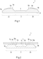
- a sealing sleeve 1 for a pipe clamp is shown in cross section, which is designed symmetrically, i.e. has mirror-inverted axial end regions 2a, 2b, between which a central region 3 with reduced material thickness is formed.
- a first sealing lips 5a, 5b and second sealing lips 6a, 6b are formed in each of the end regions 2a, 2b.
- the second sealing lips 6a, 6b are located further outward in the axial direction than the first sealing lips 5a, 5b.
- Adjacent to the second sealing lips 6a, 6b, further sealing lips 7a, 7b are arranged further outwards in the axial direction.
- the second sealing lips 6a, 6b and further sealing lips 7a, 7b essentially have a part-circular cross section and therefore act similarly to O-rings.
- the additional sealing lips 7a, 7b located axially further outward extend less far in the radial direction than the first sealing lip 5a, 5b and the second sealing lip 6a, 6b.
- a radial outside 8 of the sealing sleeve 1 is smooth.
- the sealing sleeve 1 therefore has a smooth cylindrical shape on the outside.
- the sealing sleeve 1 tapers on the inside at its axial outer edges 9a, 9b and can, for example, reach under an inwardly projecting metal strip of the pipe clamp, so that the sealing sleeve 1 can be held in a form-fitting manner within a pipe clamp.
- the middle region 3 has a reduced, constant material thickness compared to the axial end regions 2a, 2b, in which the sealing lips 5a, 5b, 6a, 6b, 7a, 7b are formed.
- This area essentially serves to clearly define a distance between the axial end areas 2a, 2b from one another.
- a band insert can be positioned between the axial end regions 2a, 2b on the inside 4, which covers the sealing sleeve 1 on the inside, i.e. on a side facing away from the pipe clamp.
- FIG 2 the sealing sleeve 1 is shown in cross section in a state braced against two pipe ends 10a, 10b. It can be seen that the sealing lips 5a, 5b have deformed axially and radially inwards. At a higher pressure within the pipe ends 10a, 10b, which then also prevails in a free space 11 radially within the central region 3, the first sealing lips 5a, 5b are pressed onto the surface of the pipe ends 10a, 10b. Increasing pressure increases the force on the first sealing lips 5a, 5b and thus also the sealing effect.
- the invention is not limited to one of the exemplary embodiments described, but can be modified in many ways.
- the shape of the second sealing lips and the further sealing lips can deviate from the part-circular cross-sectional shape shown and, for example, be pyramid-shaped.
- an additional sealing lip can also be provided which has the same cross-sectional geometry as the first sealing lip.
- the sealing sleeve according to the invention enables a secure seal even with rough surfaces of the pipe ends to be connected to one another.
- the sealing lips are at least partially very elastic, with a high sealing effect always being achieved due to the large number of sealing lips. Combined with A pipe clamp can be used to create very reliable pipe couplings.
Landscapes
- Engineering & Computer Science (AREA)
- General Engineering & Computer Science (AREA)
- Mechanical Engineering (AREA)
- Physics & Mathematics (AREA)
- Fluid Mechanics (AREA)
- Gasket Seals (AREA)
- Joints With Sleeves (AREA)
- Joints With Pressure Members (AREA)
Claims (15)
- Manchon d'étanchéité annulaire (1) pour un collier de serrage, le manchon d'étanchéité (1) présentant sur un côté intérieur (4) une première lèvre d'étanchéité (5a, 5b) avec une première géométrie de section transversale et une deuxième lèvre d'étanchéité (6a, 6b) avec une deuxième géométrie de section transversale, la première géométrie de section transversale et la deuxième géométrie de section transversale étant différentes, la première lèvre d'étanchéité (5a, 5b) présentant une extension plus grande dans la direction axiale que dans la direction radiale et la deuxième lèvre d'étanchéité (6a, 5b) présentant une extension dans la direction axiale égale ou inférieure à celle dans la direction radiale, la deuxième géométrie de section transversale étant réalisée en se rétrécissant dans la direction radiale, à savoir en forme de cercle partiel ou en forme de pyramide avec une zone de tête arrondie ou pointue, moyennant quoi la deuxième lèvre d'étanchéité (6a, 6b) agit comme un joint torique, caractérisé en ce que la première lèvre d'étanchéité (5a, 5b) est plus rigide que la deuxième lèvre d'étanchéité (6a, 6b) en raison de sa géométrie de section transversale.
- Manchon d'étanchéité selon la revendication 1, caractérisé en ce que la première lèvre d'étanchéité (5a, 5b) est inclinée vers l'intérieur dans la direction axiale en s'éloignant de la deuxième lèvre d'étanchéité (6a, 6b).
- Manchon d'étanchéité selon la revendication 1 ou 2, caractérisé en ce que la deuxième lèvre d'étanchéité (6a, 6b) est agencée axialement plus à l'extérieur que la première lèvre d'étanchéité (5a, 5b).
- Manchon d'étanchéité selon l'une quelconque des revendications précédentes, caractérisé en ce qu'il présente, au voisinage de la deuxième lèvre d'étanchéité (6a, 6b), d'autres lèvres d'étanchéité (7a, 7b) ayant la même géométrie de section transversale que la deuxième lèvre d'étanchéité (6a, 6b).
- Manchon d'étanchéité selon la revendication 4, caractérisé en ce que la deuxième lèvre d'étanchéité (6a, 6b) et les autres lèvres d'étanchéité (7a, 7b) sont peu ou pas du tout inclinées et sont plus flexibles dans la direction axiale que la première lèvre d'étanchéité (5a, 5b) .
- Manchon d'étanchéité selon l'une quelconque des revendications 4 ou 5, caractérisé en ce que d'autres lèvres d'étanchéité (7a, 7b) agencées axialement plus à l'extérieur s'étendent radialement moins loin vers l'intérieur que la première lèvre d'étanchéité (5a, 5b).
- Manchon d'étanchéité selon l'une quelconque des revendications 4 à 6, caractérisé en ce que la première lèvre d'étanchéité (5a, 5b) et la deuxième lèvre d'étanchéité (6a, 6b) s'étendent radialement plus loin vers l'intérieur qu'au moins une des autres lèvres d'étanchéité (7a, 7b).
- Manchon d'étanchéité selon l'une quelconque des revendications précédentes, caractérisé en ce qu'il est construit de manière symétrique, une combinaison d'une première lèvre d'étanchéité (5a, 5b) et d'une deuxième lèvre d'étanchéité (6a, 6b) et éventuellement d'autres lèvres d'étanchéité (7a, 7b) étant agencée à chaque zone d'extrémité axiale (2a, 2b).
- Manchon d'étanchéité selon la revendication 8, caractérisé en ce que les premières lèvres d'étanchéité (5a, 5b) sont situées axialement plus à l'intérieur que les deuxièmes lèvres d'étanchéité (6a, 6b) et éventuellement d'autres lèvres d'étanchéité (7a, 7b).
- Manchon d'étanchéité selon l'une quelconque des revendications 8 ou 9, caractérisé en ce que le manchon d'étanchéité (1) présente entre les premières lèvres d'étanchéité (5a, 5b) une zone centrale (3) d'épaisseur de matériau constante, le manchon d'étanchéité (1) étant plus mince dans cette zone centrale (3) que dans la zone des lèvres d'étanchéité (5a, 5b, 6a, 6b, 7a, 7b).
- Manchon d'étanchéité selon l'une quelconque des revendications précédentes, caractérisé en ce qu'un côté extérieur radial (8) du manchon d'étanchéité (1) est réalisé sous forme lisse.
- Manchon d'étanchéité selon l'une quelconque des revendications précédentes, caractérisé en ce que les bords extérieurs axiaux (9a, 9b) du manchon d'étanchéité (1) se rétrécissent dans la direction radiale.
- Collier de serrage avec un manchon d'étanchéité (1) selon l'une quelconque des revendications précédentes, caractérisé en ce que le manchon d'étanchéité (1) est agencé sur un côté intérieur du collier de serrage.
- Collier de serrage selon la revendication 13, caractérisé en ce qu'au moins une bande métallique pourvue de dents faisant saillie radialement vers l'intérieur est agencée sur le côté intérieur du collier de serrage.
- Collier de serrage selon l'une quelconque des revendications 13 ou 14 en combinaison avec la revendication 8, caractérisé en ce que sur le côté intérieur (4) du manchon d'étanchéité (1) est prévue une garniture de bande qui s'étend uniquement dans la zone centrale entre les lèvres d'étanchéité (5a, 5b, 6a, 6b) réalisées respectivement dans les zones d'extrémité axiales (2a, 2b).
Applications Claiming Priority (2)
| Application Number | Priority Date | Filing Date | Title |
|---|---|---|---|
| DE102017113789.0A DE102017113789A1 (de) | 2017-06-21 | 2017-06-21 | Dichtungsmanschette für eine Rohrschelle und Rohrschelle mit einer derartigen Dichtungsmanschette |
| PCT/EP2018/065944 WO2018234178A1 (fr) | 2017-06-21 | 2018-06-15 | Manchon d'étanchéité pour un collier de serrage et collier de serrage comprenant un manchon d'étanchéité de ce type |
Publications (2)
| Publication Number | Publication Date |
|---|---|
| EP3642523A1 EP3642523A1 (fr) | 2020-04-29 |
| EP3642523B1 true EP3642523B1 (fr) | 2023-12-27 |
Family
ID=62636217
Family Applications (1)
| Application Number | Title | Priority Date | Filing Date |
|---|---|---|---|
| EP18732050.2A Active EP3642523B1 (fr) | 2017-06-21 | 2018-06-15 | Manchon d'étanchéité pour un collier de serrage et collier de serrage comprenant un manchon d'étanchéité de ce type |
Country Status (6)
| Country | Link |
|---|---|
| EP (1) | EP3642523B1 (fr) |
| JP (1) | JP7049372B2 (fr) |
| KR (1) | KR20200016966A (fr) |
| CN (1) | CN110770487A (fr) |
| DE (1) | DE102017113789A1 (fr) |
| WO (1) | WO2018234178A1 (fr) |
Family Cites Families (13)
| Publication number | Priority date | Publication date | Assignee | Title |
|---|---|---|---|---|
| US1930194A (en) * | 1930-06-28 | 1933-10-10 | Stephen V Dillon | Pipe coupling |
| JPS52150815U (fr) * | 1976-05-13 | 1977-11-15 | ||
| GB8707057D0 (en) * | 1987-03-25 | 1987-04-29 | Taylor Kerr Couplings Ltd | Flexible pipe couplings |
| GB8724335D0 (en) * | 1987-10-16 | 1987-11-18 | Victaulic Plc | Pipe joint & coupling |
| CH685308A5 (de) * | 1993-12-02 | 1995-05-31 | Peter Ilesic | Dichtvorrichtung zum Abdichten von Rohrleitungen. |
| DE29608499U1 (de) * | 1996-05-10 | 1996-08-08 | Ilešič, Peter, Maribor | Rohrkupplung |
| DE20014142U1 (de) * | 2000-04-22 | 2001-02-22 | Wantoch, Manfred, 44866 Bochum | Rohrkupplung |
| CN1813150B (zh) * | 2003-04-25 | 2010-12-22 | 维克托里克公司 | 用于管接头的垫片和包括垫片的管接头 |
| JP2005090605A (ja) * | 2003-09-16 | 2005-04-07 | Riken Corp | 管継手 |
| JP2007113781A (ja) * | 2005-09-20 | 2007-05-10 | Inter Kogyo:Kk | 管継手 |
| US8646814B2 (en) * | 2007-10-03 | 2014-02-11 | Anvil International Llc | Coupling gaskets and associated methods |
| PH12012500810A1 (en) * | 2009-10-27 | 2012-11-26 | Tyco Fire Products Lp | Systems and methods for pipe couplings |
| CN204805778U (zh) * | 2015-07-10 | 2015-11-25 | 郭文星 | 管道接头 |
-
2017
- 2017-06-21 DE DE102017113789.0A patent/DE102017113789A1/de not_active Withdrawn
-
2018
- 2018-06-15 CN CN201880041499.7A patent/CN110770487A/zh active Pending
- 2018-06-15 KR KR1020207000764A patent/KR20200016966A/ko not_active Ceased
- 2018-06-15 JP JP2019571246A patent/JP7049372B2/ja active Active
- 2018-06-15 EP EP18732050.2A patent/EP3642523B1/fr active Active
- 2018-06-15 WO PCT/EP2018/065944 patent/WO2018234178A1/fr not_active Ceased
Also Published As
| Publication number | Publication date |
|---|---|
| CN110770487A (zh) | 2020-02-07 |
| KR20200016966A (ko) | 2020-02-17 |
| JP2020524771A (ja) | 2020-08-20 |
| EP3642523A1 (fr) | 2020-04-29 |
| WO2018234178A1 (fr) | 2018-12-27 |
| DE102017113789A1 (de) | 2018-12-27 |
| JP7049372B2 (ja) | 2022-04-06 |
Similar Documents
| Publication | Publication Date | Title |
|---|---|---|
| DE10119534B4 (de) | Metallische Dichtung | |
| EP0186727B1 (fr) | Raccord de conduits | |
| DE102009007303B4 (de) | Fitting für dickwandige Rohre | |
| EP2140188B1 (fr) | Soupape pour séparer des milieux de produits dans des canalisations d'une installation acheminant des produits | |
| EP2044359B1 (fr) | Manchon et combinaison de manchon avec un outil de moulage par compression | |
| EP1564469A1 (fr) | Raccord pour un raccordement serré | |
| EP3978751B1 (fr) | Membrane composite pour pompes à membrane | |
| DE2714963C3 (de) | Elastisches Rohrverbindungsstück | |
| EP0223185B1 (fr) | Raccord pour tuyaux | |
| DE202007010592U1 (de) | Anordnung zur Befestigung einer Leitung mit einem profilierten Außendurchmesser | |
| EP3364086B1 (fr) | Système de liaison destiné à raccorder une conduite | |
| DE102011119513A1 (de) | Rohrverbindung zur fluiddichten Anbindung von Komponenten einer Klimaanlage | |
| DE102015204689A1 (de) | Rohrverbindungssystem | |
| DE60214775T2 (de) | Flanschglied mit einem ersten flanschende, das in einer radialrichtung mit einer konkaven endfläche ausgeführt ist, und einer flanschgliederumfassenden flanschverbindung | |
| EP2459905B1 (fr) | Joint d'étanchéité et agencement doté d'un joint d'étanchéité | |
| DE112017007969T5 (de) | Kolbendichtungsbaugruppe für ein Kupplungsausrücksystem sowie Kupplungsausrücksystem | |
| EP3464963A1 (fr) | Joint à gorge et son procédé de fabrication | |
| EP2801725B1 (fr) | Dispositif comprenant au moins un canal pour l'acheminement d'un fluide de travail gazeux ou liquide | |
| EP0177761A1 (fr) | Joint d'étanchéité frontal | |
| DE19635053C2 (de) | Schlaucharmatur für Druckschläuche | |
| DE202013007855U1 (de) | Dichteinrichtung für Rohrverbindungen | |
| DE4124221C2 (de) | Dichtring | |
| WO2018234178A1 (fr) | Manchon d'étanchéité pour un collier de serrage et collier de serrage comprenant un manchon d'étanchéité de ce type | |
| DE102020108722A1 (de) | Kammprofildichtring und Flanschverbindung | |
| DE1937399C3 (de) | Vorrichtung zum abgedichteten Aneinanderkuppeln von fließfähige Medien führenden Elementen, beispielsweise Leitungsrohren |
Legal Events
| Date | Code | Title | Description |
|---|---|---|---|
| STAA | Information on the status of an ep patent application or granted ep patent |
Free format text: STATUS: UNKNOWN |
|
| STAA | Information on the status of an ep patent application or granted ep patent |
Free format text: STATUS: THE INTERNATIONAL PUBLICATION HAS BEEN MADE |
|
| PUAI | Public reference made under article 153(3) epc to a published international application that has entered the european phase |
Free format text: ORIGINAL CODE: 0009012 |
|
| STAA | Information on the status of an ep patent application or granted ep patent |
Free format text: STATUS: REQUEST FOR EXAMINATION WAS MADE |
|
| 17P | Request for examination filed |
Effective date: 20200113 |
|
| AK | Designated contracting states |
Kind code of ref document: A1 Designated state(s): AL AT BE BG CH CY CZ DE DK EE ES FI FR GB GR HR HU IE IS IT LI LT LU LV MC MK MT NL NO PL PT RO RS SE SI SK SM TR |
|
| AX | Request for extension of the european patent |
Extension state: BA ME |
|
| DAV | Request for validation of the european patent (deleted) | ||
| DAX | Request for extension of the european patent (deleted) | ||
| STAA | Information on the status of an ep patent application or granted ep patent |
Free format text: STATUS: EXAMINATION IS IN PROGRESS |
|
| 17Q | First examination report despatched |
Effective date: 20220301 |
|
| GRAP | Despatch of communication of intention to grant a patent |
Free format text: ORIGINAL CODE: EPIDOSNIGR1 |
|
| STAA | Information on the status of an ep patent application or granted ep patent |
Free format text: STATUS: GRANT OF PATENT IS INTENDED |
|
| INTG | Intention to grant announced |
Effective date: 20230802 |
|
| GRAS | Grant fee paid |
Free format text: ORIGINAL CODE: EPIDOSNIGR3 |
|
| GRAA | (expected) grant |
Free format text: ORIGINAL CODE: 0009210 |
|
| STAA | Information on the status of an ep patent application or granted ep patent |
Free format text: STATUS: THE PATENT HAS BEEN GRANTED |
|
| AK | Designated contracting states |
Kind code of ref document: B1 Designated state(s): AL AT BE BG CH CY CZ DE DK EE ES FI FR GB GR HR HU IE IS IT LI LT LU LV MC MK MT NL NO PL PT RO RS SE SI SK SM TR |
|
| REG | Reference to a national code |
Ref country code: GB Ref legal event code: FG4D Free format text: NOT ENGLISH |
|
| REG | Reference to a national code |
Ref country code: CH Ref legal event code: EP |
|
| REG | Reference to a national code |
Ref country code: DE Ref legal event code: R096 Ref document number: 502018013869 Country of ref document: DE |
|
| REG | Reference to a national code |
Ref country code: IE Ref legal event code: FG4D Free format text: LANGUAGE OF EP DOCUMENT: GERMAN |
|
| PG25 | Lapsed in a contracting state [announced via postgrant information from national office to epo] |
Ref country code: GR Free format text: LAPSE BECAUSE OF FAILURE TO SUBMIT A TRANSLATION OF THE DESCRIPTION OR TO PAY THE FEE WITHIN THE PRESCRIBED TIME-LIMIT Effective date: 20240328 |
|
| REG | Reference to a national code |
Ref country code: LT Ref legal event code: MG9D |
|
| PG25 | Lapsed in a contracting state [announced via postgrant information from national office to epo] |
Ref country code: LT Free format text: LAPSE BECAUSE OF FAILURE TO SUBMIT A TRANSLATION OF THE DESCRIPTION OR TO PAY THE FEE WITHIN THE PRESCRIBED TIME-LIMIT Effective date: 20231227 |
|
| PG25 | Lapsed in a contracting state [announced via postgrant information from national office to epo] |
Ref country code: ES Free format text: LAPSE BECAUSE OF FAILURE TO SUBMIT A TRANSLATION OF THE DESCRIPTION OR TO PAY THE FEE WITHIN THE PRESCRIBED TIME-LIMIT Effective date: 20231227 |
|
| PG25 | Lapsed in a contracting state [announced via postgrant information from national office to epo] |
Ref country code: LT Free format text: LAPSE BECAUSE OF FAILURE TO SUBMIT A TRANSLATION OF THE DESCRIPTION OR TO PAY THE FEE WITHIN THE PRESCRIBED TIME-LIMIT Effective date: 20231227 Ref country code: GR Free format text: LAPSE BECAUSE OF FAILURE TO SUBMIT A TRANSLATION OF THE DESCRIPTION OR TO PAY THE FEE WITHIN THE PRESCRIBED TIME-LIMIT Effective date: 20240328 Ref country code: FI Free format text: LAPSE BECAUSE OF FAILURE TO SUBMIT A TRANSLATION OF THE DESCRIPTION OR TO PAY THE FEE WITHIN THE PRESCRIBED TIME-LIMIT Effective date: 20231227 Ref country code: ES Free format text: LAPSE BECAUSE OF FAILURE TO SUBMIT A TRANSLATION OF THE DESCRIPTION OR TO PAY THE FEE WITHIN THE PRESCRIBED TIME-LIMIT Effective date: 20231227 Ref country code: BG Free format text: LAPSE BECAUSE OF FAILURE TO SUBMIT A TRANSLATION OF THE DESCRIPTION OR TO PAY THE FEE WITHIN THE PRESCRIBED TIME-LIMIT Effective date: 20240327 |
|
| REG | Reference to a national code |
Ref country code: NL Ref legal event code: MP Effective date: 20231227 |
|
| PG25 | Lapsed in a contracting state [announced via postgrant information from national office to epo] |
Ref country code: NL Free format text: LAPSE BECAUSE OF FAILURE TO SUBMIT A TRANSLATION OF THE DESCRIPTION OR TO PAY THE FEE WITHIN THE PRESCRIBED TIME-LIMIT Effective date: 20231227 |
|
| PG25 | Lapsed in a contracting state [announced via postgrant information from national office to epo] |
Ref country code: SE Free format text: LAPSE BECAUSE OF FAILURE TO SUBMIT A TRANSLATION OF THE DESCRIPTION OR TO PAY THE FEE WITHIN THE PRESCRIBED TIME-LIMIT Effective date: 20231227 Ref country code: RS Free format text: LAPSE BECAUSE OF FAILURE TO SUBMIT A TRANSLATION OF THE DESCRIPTION OR TO PAY THE FEE WITHIN THE PRESCRIBED TIME-LIMIT Effective date: 20231227 Ref country code: NO Free format text: LAPSE BECAUSE OF FAILURE TO SUBMIT A TRANSLATION OF THE DESCRIPTION OR TO PAY THE FEE WITHIN THE PRESCRIBED TIME-LIMIT Effective date: 20240327 Ref country code: NL Free format text: LAPSE BECAUSE OF FAILURE TO SUBMIT A TRANSLATION OF THE DESCRIPTION OR TO PAY THE FEE WITHIN THE PRESCRIBED TIME-LIMIT Effective date: 20231227 Ref country code: LV Free format text: LAPSE BECAUSE OF FAILURE TO SUBMIT A TRANSLATION OF THE DESCRIPTION OR TO PAY THE FEE WITHIN THE PRESCRIBED TIME-LIMIT Effective date: 20231227 Ref country code: HR Free format text: LAPSE BECAUSE OF FAILURE TO SUBMIT A TRANSLATION OF THE DESCRIPTION OR TO PAY THE FEE WITHIN THE PRESCRIBED TIME-LIMIT Effective date: 20231227 |
|
| PG25 | Lapsed in a contracting state [announced via postgrant information from national office to epo] |
Ref country code: IS Free format text: LAPSE BECAUSE OF FAILURE TO SUBMIT A TRANSLATION OF THE DESCRIPTION OR TO PAY THE FEE WITHIN THE PRESCRIBED TIME-LIMIT Effective date: 20240427 |
|
| PG25 | Lapsed in a contracting state [announced via postgrant information from national office to epo] |
Ref country code: CZ Free format text: LAPSE BECAUSE OF FAILURE TO SUBMIT A TRANSLATION OF THE DESCRIPTION OR TO PAY THE FEE WITHIN THE PRESCRIBED TIME-LIMIT Effective date: 20231227 |
|
| PG25 | Lapsed in a contracting state [announced via postgrant information from national office to epo] |
Ref country code: SK Free format text: LAPSE BECAUSE OF FAILURE TO SUBMIT A TRANSLATION OF THE DESCRIPTION OR TO PAY THE FEE WITHIN THE PRESCRIBED TIME-LIMIT Effective date: 20231227 |
|
| PG25 | Lapsed in a contracting state [announced via postgrant information from national office to epo] |
Ref country code: SM Free format text: LAPSE BECAUSE OF FAILURE TO SUBMIT A TRANSLATION OF THE DESCRIPTION OR TO PAY THE FEE WITHIN THE PRESCRIBED TIME-LIMIT Effective date: 20231227 Ref country code: SK Free format text: LAPSE BECAUSE OF FAILURE TO SUBMIT A TRANSLATION OF THE DESCRIPTION OR TO PAY THE FEE WITHIN THE PRESCRIBED TIME-LIMIT Effective date: 20231227 Ref country code: RO Free format text: LAPSE BECAUSE OF FAILURE TO SUBMIT A TRANSLATION OF THE DESCRIPTION OR TO PAY THE FEE WITHIN THE PRESCRIBED TIME-LIMIT Effective date: 20231227 Ref country code: IT Free format text: LAPSE BECAUSE OF FAILURE TO SUBMIT A TRANSLATION OF THE DESCRIPTION OR TO PAY THE FEE WITHIN THE PRESCRIBED TIME-LIMIT Effective date: 20231227 Ref country code: IS Free format text: LAPSE BECAUSE OF FAILURE TO SUBMIT A TRANSLATION OF THE DESCRIPTION OR TO PAY THE FEE WITHIN THE PRESCRIBED TIME-LIMIT Effective date: 20240427 Ref country code: EE Free format text: LAPSE BECAUSE OF FAILURE TO SUBMIT A TRANSLATION OF THE DESCRIPTION OR TO PAY THE FEE WITHIN THE PRESCRIBED TIME-LIMIT Effective date: 20231227 Ref country code: CZ Free format text: LAPSE BECAUSE OF FAILURE TO SUBMIT A TRANSLATION OF THE DESCRIPTION OR TO PAY THE FEE WITHIN THE PRESCRIBED TIME-LIMIT Effective date: 20231227 |
|
| PG25 | Lapsed in a contracting state [announced via postgrant information from national office to epo] |
Ref country code: PL Free format text: LAPSE BECAUSE OF FAILURE TO SUBMIT A TRANSLATION OF THE DESCRIPTION OR TO PAY THE FEE WITHIN THE PRESCRIBED TIME-LIMIT Effective date: 20231227 Ref country code: PT Free format text: LAPSE BECAUSE OF FAILURE TO SUBMIT A TRANSLATION OF THE DESCRIPTION OR TO PAY THE FEE WITHIN THE PRESCRIBED TIME-LIMIT Effective date: 20240429 |
|
| PG25 | Lapsed in a contracting state [announced via postgrant information from national office to epo] |
Ref country code: PT Free format text: LAPSE BECAUSE OF FAILURE TO SUBMIT A TRANSLATION OF THE DESCRIPTION OR TO PAY THE FEE WITHIN THE PRESCRIBED TIME-LIMIT Effective date: 20240429 Ref country code: PL Free format text: LAPSE BECAUSE OF FAILURE TO SUBMIT A TRANSLATION OF THE DESCRIPTION OR TO PAY THE FEE WITHIN THE PRESCRIBED TIME-LIMIT Effective date: 20231227 |
|
| REG | Reference to a national code |
Ref country code: DE Ref legal event code: R097 Ref document number: 502018013869 Country of ref document: DE |
|
| PG25 | Lapsed in a contracting state [announced via postgrant information from national office to epo] |
Ref country code: DK Free format text: LAPSE BECAUSE OF FAILURE TO SUBMIT A TRANSLATION OF THE DESCRIPTION OR TO PAY THE FEE WITHIN THE PRESCRIBED TIME-LIMIT Effective date: 20231227 |
|
| PG25 | Lapsed in a contracting state [announced via postgrant information from national office to epo] |
Ref country code: DK Free format text: LAPSE BECAUSE OF FAILURE TO SUBMIT A TRANSLATION OF THE DESCRIPTION OR TO PAY THE FEE WITHIN THE PRESCRIBED TIME-LIMIT Effective date: 20231227 |
|
| PLBE | No opposition filed within time limit |
Free format text: ORIGINAL CODE: 0009261 |
|
| STAA | Information on the status of an ep patent application or granted ep patent |
Free format text: STATUS: NO OPPOSITION FILED WITHIN TIME LIMIT |
|
| 26N | No opposition filed |
Effective date: 20240930 |
|
| PG25 | Lapsed in a contracting state [announced via postgrant information from national office to epo] |
Ref country code: MC Free format text: LAPSE BECAUSE OF FAILURE TO SUBMIT A TRANSLATION OF THE DESCRIPTION OR TO PAY THE FEE WITHIN THE PRESCRIBED TIME-LIMIT Effective date: 20231227 |
|
| REG | Reference to a national code |
Ref country code: CH Ref legal event code: PL |
|
| PG25 | Lapsed in a contracting state [announced via postgrant information from national office to epo] |
Ref country code: LU Free format text: LAPSE BECAUSE OF NON-PAYMENT OF DUE FEES Effective date: 20240615 |
|
| PG25 | Lapsed in a contracting state [announced via postgrant information from national office to epo] |
Ref country code: IE Free format text: LAPSE BECAUSE OF NON-PAYMENT OF DUE FEES Effective date: 20240615 |
|
| PG25 | Lapsed in a contracting state [announced via postgrant information from national office to epo] |
Ref country code: SI Free format text: LAPSE BECAUSE OF FAILURE TO SUBMIT A TRANSLATION OF THE DESCRIPTION OR TO PAY THE FEE WITHIN THE PRESCRIBED TIME-LIMIT Effective date: 20231227 Ref country code: BE Free format text: LAPSE BECAUSE OF NON-PAYMENT OF DUE FEES Effective date: 20240630 Ref country code: CH Free format text: LAPSE BECAUSE OF NON-PAYMENT OF DUE FEES Effective date: 20240630 |
|
| REG | Reference to a national code |
Ref country code: BE Ref legal event code: MM Effective date: 20240630 |
|
| PGFP | Annual fee paid to national office [announced via postgrant information from national office to epo] |
Ref country code: DE Payment date: 20250627 Year of fee payment: 8 |
|
| PGFP | Annual fee paid to national office [announced via postgrant information from national office to epo] |
Ref country code: GB Payment date: 20250627 Year of fee payment: 8 |
|
| PGFP | Annual fee paid to national office [announced via postgrant information from national office to epo] |
Ref country code: FR Payment date: 20250625 Year of fee payment: 8 |
|
| REG | Reference to a national code |
Ref country code: AT Ref legal event code: MM01 Ref document number: 1644818 Country of ref document: AT Kind code of ref document: T Effective date: 20240615 |
|
| PG25 | Lapsed in a contracting state [announced via postgrant information from national office to epo] |
Ref country code: AT Free format text: LAPSE BECAUSE OF NON-PAYMENT OF DUE FEES Effective date: 20240615 |
|
| PG25 | Lapsed in a contracting state [announced via postgrant information from national office to epo] |
Ref country code: CY Free format text: LAPSE BECAUSE OF FAILURE TO SUBMIT A TRANSLATION OF THE DESCRIPTION OR TO PAY THE FEE WITHIN THE PRESCRIBED TIME-LIMIT; INVALID AB INITIO Effective date: 20180615 |
|
| PG25 | Lapsed in a contracting state [announced via postgrant information from national office to epo] |
Ref country code: HU Free format text: LAPSE BECAUSE OF FAILURE TO SUBMIT A TRANSLATION OF THE DESCRIPTION OR TO PAY THE FEE WITHIN THE PRESCRIBED TIME-LIMIT; INVALID AB INITIO Effective date: 20180615 |