EP3642663B1 - Procédé de fabrication d'article optique et appareil de modelage optique - Google Patents
Procédé de fabrication d'article optique et appareil de modelage optique Download PDFInfo
- Publication number
- EP3642663B1 EP3642663B1 EP17737384.2A EP17737384A EP3642663B1 EP 3642663 B1 EP3642663 B1 EP 3642663B1 EP 17737384 A EP17737384 A EP 17737384A EP 3642663 B1 EP3642663 B1 EP 3642663B1
- Authority
- EP
- European Patent Office
- Prior art keywords
- stage
- output
- light
- optical
- optical article
- Prior art date
- Legal status (The legal status is an assumption and is not a legal conclusion. Google has not performed a legal analysis and makes no representation as to the accuracy of the status listed.)
- Active
Links
Images





Classifications
-
- B—PERFORMING OPERATIONS; TRANSPORTING
- B29—WORKING OF PLASTICS; WORKING OF SUBSTANCES IN A PLASTIC STATE IN GENERAL
- B29C—SHAPING OR JOINING OF PLASTICS; SHAPING OF MATERIAL IN A PLASTIC STATE, NOT OTHERWISE PROVIDED FOR; AFTER-TREATMENT OF THE SHAPED PRODUCTS, e.g. REPAIRING
- B29C64/00—Additive manufacturing, i.e. manufacturing of three-dimensional [3D] objects by additive deposition, additive agglomeration or additive layering, e.g. by 3D printing, stereolithography or selective laser sintering
- B29C64/10—Processes of additive manufacturing
- B29C64/106—Processes of additive manufacturing using only liquids or viscous materials, e.g. depositing a continuous bead of viscous material
- B29C64/124—Processes of additive manufacturing using only liquids or viscous materials, e.g. depositing a continuous bead of viscous material using layers of liquid which are selectively solidified
- B29C64/129—Processes of additive manufacturing using only liquids or viscous materials, e.g. depositing a continuous bead of viscous material using layers of liquid which are selectively solidified characterised by the energy source therefor, e.g. by global irradiation combined with a mask
-
- B—PERFORMING OPERATIONS; TRANSPORTING
- B29—WORKING OF PLASTICS; WORKING OF SUBSTANCES IN A PLASTIC STATE IN GENERAL
- B29C—SHAPING OR JOINING OF PLASTICS; SHAPING OF MATERIAL IN A PLASTIC STATE, NOT OTHERWISE PROVIDED FOR; AFTER-TREATMENT OF THE SHAPED PRODUCTS, e.g. REPAIRING
- B29C64/00—Additive manufacturing, i.e. manufacturing of three-dimensional [3D] objects by additive deposition, additive agglomeration or additive layering, e.g. by 3D printing, stereolithography or selective laser sintering
- B29C64/10—Processes of additive manufacturing
- B29C64/106—Processes of additive manufacturing using only liquids or viscous materials, e.g. depositing a continuous bead of viscous material
- B29C64/124—Processes of additive manufacturing using only liquids or viscous materials, e.g. depositing a continuous bead of viscous material using layers of liquid which are selectively solidified
-
- B—PERFORMING OPERATIONS; TRANSPORTING
- B29—WORKING OF PLASTICS; WORKING OF SUBSTANCES IN A PLASTIC STATE IN GENERAL
- B29C—SHAPING OR JOINING OF PLASTICS; SHAPING OF MATERIAL IN A PLASTIC STATE, NOT OTHERWISE PROVIDED FOR; AFTER-TREATMENT OF THE SHAPED PRODUCTS, e.g. REPAIRING
- B29C64/00—Additive manufacturing, i.e. manufacturing of three-dimensional [3D] objects by additive deposition, additive agglomeration or additive layering, e.g. by 3D printing, stereolithography or selective laser sintering
- B29C64/20—Apparatus for additive manufacturing; Details thereof or accessories therefor
- B29C64/264—Arrangements for irradiation
-
- B—PERFORMING OPERATIONS; TRANSPORTING
- B29—WORKING OF PLASTICS; WORKING OF SUBSTANCES IN A PLASTIC STATE IN GENERAL
- B29C—SHAPING OR JOINING OF PLASTICS; SHAPING OF MATERIAL IN A PLASTIC STATE, NOT OTHERWISE PROVIDED FOR; AFTER-TREATMENT OF THE SHAPED PRODUCTS, e.g. REPAIRING
- B29C64/00—Additive manufacturing, i.e. manufacturing of three-dimensional [3D] objects by additive deposition, additive agglomeration or additive layering, e.g. by 3D printing, stereolithography or selective laser sintering
- B29C64/20—Apparatus for additive manufacturing; Details thereof or accessories therefor
- B29C64/264—Arrangements for irradiation
- B29C64/277—Arrangements for irradiation using multiple radiation means, e.g. micromirrors or multiple light-emitting diodes [LED]
-
- B—PERFORMING OPERATIONS; TRANSPORTING
- B29—WORKING OF PLASTICS; WORKING OF SUBSTANCES IN A PLASTIC STATE IN GENERAL
- B29C—SHAPING OR JOINING OF PLASTICS; SHAPING OF MATERIAL IN A PLASTIC STATE, NOT OTHERWISE PROVIDED FOR; AFTER-TREATMENT OF THE SHAPED PRODUCTS, e.g. REPAIRING
- B29C64/00—Additive manufacturing, i.e. manufacturing of three-dimensional [3D] objects by additive deposition, additive agglomeration or additive layering, e.g. by 3D printing, stereolithography or selective laser sintering
- B29C64/30—Auxiliary operations or equipment
- B29C64/386—Data acquisition or data processing for additive manufacturing
- B29C64/393—Data acquisition or data processing for additive manufacturing for controlling or regulating additive manufacturing processes
-
- B—PERFORMING OPERATIONS; TRANSPORTING
- B29—WORKING OF PLASTICS; WORKING OF SUBSTANCES IN A PLASTIC STATE IN GENERAL
- B29D—PRODUCING PARTICULAR ARTICLES FROM PLASTICS OR FROM SUBSTANCES IN A PLASTIC STATE
- B29D11/00—Producing optical elements, e.g. lenses or prisms
- B29D11/00009—Production of simple or compound lenses
-
- B—PERFORMING OPERATIONS; TRANSPORTING
- B29—WORKING OF PLASTICS; WORKING OF SUBSTANCES IN A PLASTIC STATE IN GENERAL
- B29D—PRODUCING PARTICULAR ARTICLES FROM PLASTICS OR FROM SUBSTANCES IN A PLASTIC STATE
- B29D11/00—Producing optical elements, e.g. lenses or prisms
- B29D11/00009—Production of simple or compound lenses
- B29D11/00432—Auxiliary operations, e.g. machines for filling the moulds
-
- B—PERFORMING OPERATIONS; TRANSPORTING
- B33—ADDITIVE MANUFACTURING TECHNOLOGY
- B33Y—ADDITIVE MANUFACTURING, i.e. MANUFACTURING OF THREE-DIMENSIONAL [3D] OBJECTS BY ADDITIVE DEPOSITION, ADDITIVE AGGLOMERATION OR ADDITIVE LAYERING, e.g. BY 3D PRINTING, STEREOLITHOGRAPHY OR SELECTIVE LASER SINTERING
- B33Y10/00—Processes of additive manufacturing
-
- B—PERFORMING OPERATIONS; TRANSPORTING
- B33—ADDITIVE MANUFACTURING TECHNOLOGY
- B33Y—ADDITIVE MANUFACTURING, i.e. MANUFACTURING OF THREE-DIMENSIONAL [3D] OBJECTS BY ADDITIVE DEPOSITION, ADDITIVE AGGLOMERATION OR ADDITIVE LAYERING, e.g. BY 3D PRINTING, STEREOLITHOGRAPHY OR SELECTIVE LASER SINTERING
- B33Y30/00—Apparatus for additive manufacturing; Details thereof or accessories therefor
-
- B—PERFORMING OPERATIONS; TRANSPORTING
- B33—ADDITIVE MANUFACTURING TECHNOLOGY
- B33Y—ADDITIVE MANUFACTURING, i.e. MANUFACTURING OF THREE-DIMENSIONAL [3D] OBJECTS BY ADDITIVE DEPOSITION, ADDITIVE AGGLOMERATION OR ADDITIVE LAYERING, e.g. BY 3D PRINTING, STEREOLITHOGRAPHY OR SELECTIVE LASER SINTERING
- B33Y50/00—Data acquisition or data processing for additive manufacturing
- B33Y50/02—Data acquisition or data processing for additive manufacturing for controlling or regulating additive manufacturing processes
-
- G—PHYSICS
- G02—OPTICS
- G02B—OPTICAL ELEMENTS, SYSTEMS OR APPARATUS
- G02B26/00—Optical devices or arrangements for the control of light using movable or deformable optical elements
- G02B26/08—Optical devices or arrangements for the control of light using movable or deformable optical elements for controlling the direction of light
- G02B26/0816—Optical devices or arrangements for the control of light using movable or deformable optical elements for controlling the direction of light by means of one or more reflecting elements
- G02B26/0833—Optical devices or arrangements for the control of light using movable or deformable optical elements for controlling the direction of light by means of one or more reflecting elements the reflecting element being a micromechanical device, e.g. a MEMS mirror, DMD
-
- G—PHYSICS
- G03—PHOTOGRAPHY; CINEMATOGRAPHY; ANALOGOUS TECHNIQUES USING WAVES OTHER THAN OPTICAL WAVES; ELECTROGRAPHY; HOLOGRAPHY
- G03F—PHOTOMECHANICAL PRODUCTION OF TEXTURED OR PATTERNED SURFACES, e.g. FOR PRINTING, FOR PROCESSING OF SEMICONDUCTOR DEVICES; MATERIALS THEREFOR; ORIGINALS THEREFOR; APPARATUS SPECIALLY ADAPTED THEREFOR
- G03F7/00—Photomechanical, e.g. photolithographic, production of textured or patterned surfaces, e.g. printing surfaces; Materials therefor, e.g. comprising photoresists; Apparatus specially adapted therefor
- G03F7/70—Microphotolithographic exposure; Apparatus therefor
- G03F7/70416—2.5D lithography
-
- B—PERFORMING OPERATIONS; TRANSPORTING
- B33—ADDITIVE MANUFACTURING TECHNOLOGY
- B33Y—ADDITIVE MANUFACTURING, i.e. MANUFACTURING OF THREE-DIMENSIONAL [3D] OBJECTS BY ADDITIVE DEPOSITION, ADDITIVE AGGLOMERATION OR ADDITIVE LAYERING, e.g. BY 3D PRINTING, STEREOLITHOGRAPHY OR SELECTIVE LASER SINTERING
- B33Y80/00—Products made by additive manufacturing
Definitions
- the present invention relates to a method of manufacturing an optical article and an optical shaping apparatus.
- the invention is defined by the accompanying claims.
- Patent Literature 1 A method for shaping an object layer by layer from a plurality of solidified layers by repeating steps by irradiating a light-curable resin (photopolymer) in a container through a bottom portion of a container which stores the light-curable resin with light, is known (Patent Literature 1).
- a micromirror device e.g. a DMD (Digital Micromirror Device)
- DMD Digital Micromirror Device
- the micromirror device has a plurality of micromirrors arranged on the surface thereof in two-dimensional repetition structure.
- a desired shape of reflection region is generated on the surface of the micromirror device by selectively controlling a direction of reflective surface of each of the micromirrors, and an image of the reflection region is projected to the light-curable resin.
- the present inventors have identified that using DMD-base stereolithography as explained above the resulting manufactured optical article induces stereoscopic diffraction. When a light enters such optical article, diffracted light is generated, which make it difficult to use the optical article for its initial purpose.
- the present inventors note that this happens despite that an each layer of the optical article is insulated as a whole in each successive step of the process, in other words, it is the state that the whole of the optical article is not completely homogeneous and the laminating of each layer is in recognizable.
- an optical article like a lens using such an optical component does not have high optical performance because of a generation of the diffracted light as explained above.
- Acceptable level of the diffracted light generation depends on a required optical performance to the optical article.
- the present inventors propose a mechanism that could explain the formation of a diffracting structure when none was expected. Further, the present inventors propose technical solutions that enable to reduce the discomfort brought by the diffracting effect or even produce an optical article without this diffracting effect.
- an intensity of the projected light in a portion corresponding to an area of the micromirror itself is different from that in a portion corresponding to an area between adjacent micromirrors. Due to this, there is a subtle difference in a state of the light-curable resin between these two portions, and a reticulated periodical refractive index distribution corresponding to two-dimensional array of the micromirrors is generated in the cured layer of the light-curable resin.
- the reticulated refractive index distribution is formed in the same position in layer by layer, stereoscopic periodical refractive index distribution is observed in the resulting manufactured optical article.
- diffracted light is generated due to the above-explained refractive index distribution. This phenomenon is explained next with reference to FIGs. 8 and 9 .
- FIG. 8 shows a case in which a light enters a conventional optical article along the direction of cured layer stacking, namely along the direction of the Z-axis.
- FIG. 9 shows a case in which the light enters the conventional optical article along the direction of the surface of cured layer, namely along the direction of the X-axis.
- straight line and dotted line inside the optical articles schematically show the domain at which the refractive index is different from that of periphery.
- the light which entered the optical article passes through the stereoscopic periodical refractive index distribution explained above. In consequence, the diffracted light is generated in both cases.
- a method of manufacturing an optical article comprises: an output light flux generating process of generating an output light flux by inputting a light propagated from a light source to an output setting element having a repetition structure that generates a desired shape of output area and maintaining the desired shape of the output area for a desired period; a cured layer forming process of forming a cured layer at an irradiation area that is formed in correspondence with the output area by introducing the output light flux through a projection optical system into a container in which light-curable resin in a liquid state is contained and a stage is arranged and condensing the output light flux; a first direction stage moving process of moving the stage in a desired distance along the first direction of the output flux propagating, wherein the output light flux generating process, the cured layer forming process and the first direction stage moving process are sequentially performed in this order, and thereby forming the optical article in a repetition structure on a surface of the stage, and wherein the method further comprises an irradi
- the diffraction effect formed either by repetition structure by the output setting element or by repeating the forming of a layer above a prior layer can be reduced.
- the irradiation variation process is conducted by at least one of: an output light flux diffusion by passing the output light flux through a diffusion element in a diffusion angle of 5 to 25 degrees that is arranged at the container or at the vicinity of the container; a second direction stage movement by moving the stage in a second direction which is perpendicular to the first direction in the cured layer generating process; a condensing position adjusting so that a condensing position of the output light flux by the projection optical system deviates from the position at which the cured layer is to be formed; a magnification variation by varying a magnification of the projection optical system in each of the cured layer generating processes; and a first direction stage moving distance setting in the first direction stage moving process by setting at least two different values.
- the irradiation variation process is conducted by at least one of: a second direction stage movement by moving the stage in a second direction which is perpendicular to the first direction in the cured layer generating process; a condensing position adjusting so that a condensing position of the output light flux by the projection optical system deviates from the position at which the cured layer is to be formed; a magnification variation by varying a magnification of the projection optical system in each of the cured layer generating processes; and a first direction stage moving distance setting in the first direction stage moving process by setting at least two different values; or a combination thereof.
- the irradiation variation process is conducted by at least one of: an output light flux diffusion by passing the output light flux through a diffusion element in a diffusion angle of 5 to 25 degrees that is arranged at the container or at the vicinity of the container; and a condensing position adjusting so that a condensing position of the output light flux by the projection optical system deviates from the position at which the cured layer is to be formed.
- the irradiation variation process is conducted by at least one of: a second direction stage movement by moving the stage in a second direction which is perpendicular to the first direction in the cured layer generating process; a magnification variation by varying a magnification of the projection optical system in each of the cured layer generating processes ; and a first direction stage moving distance setting in the first direction stage moving process by setting at least two different values.
- the irradiation variation process is conducted by at least one of: an output light flux diffusion by passing the output light flux through a diffusion element in a diffusion angle of 5 to 25 degrees that is arranged at the container or at the vicinity of the container; and a condensing position adjusting so that a condensing position of the output light flux by the projection optical system deviates from the position at which the cured layer is to be formed, and at least one of: a second direction stage movement by moving the stage in a second direction which is perpendicular to the first direction in the cured layer generating process ; and a magnification variation by varying a magnification of the projection optical system in each of the cured layer generating processes ; and a first direction stage moving distance setting in the first direction stage moving process by setting at least two different values.
- the output setting element is a micromirror device that includes a plurality of micromirrors
- a reflective surface of each of the micromirrors can be set individually; the desired shape of output area is generated by controlling the reflective surface of each of the micromirrors; the output light flux is a reflected light flux which is reflected at the output area of the micromirror device; and a surface image in accordance with the output area of the micromirror device is formed at the irradiation area.
- the diffusion angle of the output light flux passed through the diffusion element is in a diffusion angle of 8 to 12 degrees.
- the desired distance to be set for the first direction stage moving process has at least two different values.
- the irradiation variation process is further conducted by at least one of: an output light flux diffusion by passing the output light flux through a diffusion element in a diffusion angle of 5 to 25 degrees that is arranged at the container or at the vicinity of the container; a second direction stage movement by moving the stage in a second direction which is perpendicular to the first direction in the cured layer generating process; a condensing position adjusting so that a condensing position of the output light flux by the projection optical system deviates from the position at which the cured layer is to be formed; and a magnification variation by varying a magnification of the projection optical system in each of the cured layer generating processes or a combination thereof.
- the irradiation variation process is further conducted by at least one of: a second direction stage movement by moving the stage in a second direction which is perpendicular to the first direction in the cured layer generating process; a condensing position adjusting so that a condensing position of the output light flux by the projection optical system deviates from the position at which the cured layer is to be formed; and a magnification variation by varying a magnification of the projection optical system in each of the cured layer generating processes or a combination thereof.
- the irradiation variation process is further conducted by at least one of: an output light flux diffusion by passing the output light flux through a diffusion element in a diffusion angle of 5 to 25 degrees that is arranged at the container or at the vicinity of the container and a condensing position adjusting so that a condensing position of the output light flux by the projection optical system deviates from the position at which the cured layer is to be formed.
- the irradiation variation process is further conducted by at least one of: a second direction stage movement by moving the stage in a second direction which is perpendicular to the first direction in the cured layer generating process; and a magnification variation by varying a magnification of the projection optical system in each of the cured layer generating processes.
- the irradiation variation process is further conducted by at least one of: an output light flux diffusion by passing the output light flux through a diffusion element in a diffusion angle of 5 to 25 degrees that is arranged at the container or at the vicinity of the container; and a condensing position adjusting so that a condensing position of the output light flux by the projection optical system deviates from the position at which the cured layer is to be formed, and at least one of: a second direction stage movement by moving the stage in a second direction which is perpendicular to the first direction in the cured layer generating process; and a magnification variation by varying a magnification of the projection optical system in each of the cured layer generating processes.
- the desired distance to be set for the first direction stage moving process is randomized.
- the desired distance to be set for the first direction stage moving process randomized as satisfying the following expression (1) P ⁇ 1 / T / P ⁇ 0 ⁇ 0.001 where, P ⁇ (0) ⁇ 1, T represents a constant value, T+ ⁇ k represents the k-th desired distance according to the thickness of the k-th layer, ⁇ k represents a randomized value following a probability distribution of the Fourier transform of ⁇ k's probability density function P ⁇ .
- an optical shaping apparatus comprises: a light source; a container that contains light-curable resin; an output setting element having a repetition structure that receives a light propagated from the light source and sets an output light flux outputting toward the container; a stage that is, arranged in the container, movable along a first direction of the output flux propagating, and cured layer generated by curing the light-curable resin is formed on a surface thereof; a stage driving mechanism that drives the stage; a projection optical system that forms an irradiation area by condensing and introducing the output light flux into the container; and a first control unit, wherein the output setting element can generate a desired shape of output area and maintaining the desired shape of the output area for a desired period, the first control unit performs: a first controlling that performs to control the output setting element so as to generate a desired shape of output area and maintaining the desired shape of the output area for a desired period; and a second controlling that performs to control the stage drive mechanism so as to move
- the optical shaping apparatus comprises at least one of: a diffusion element diffuses the output light flux in a diffusion angle of 5 to 25 degrees arranged at the container or at the position being equal to or less than 5 mm from a surface of the container, a second control unit that controls a movement of the stage in a second direction which is perpendicular to the first direction; a third control unit that controls so as to change a condensing position of the projection optical system; a fourth control unit controls so as to change a magnification of the projection optical system; and a fifth control unit controls to set the desired distance at least two different values in the second controlling.
- the optical shaping apparatus is a micromirror device that includes a plurality of micromirrors, a reflective surface of each of the micromirrors can be set individually; the desired shape of output area is generated by controlling the reflective surface of each of the micro mirrors; the output light flux is a reflected light flux which is reflected at the output area of the micromirror device; and a surface image in accordance with the output area of the micromirror device is formed at the irradiation area.
- the optical shaping apparatus according to the ninth aspect, it is preferred that the diffusion element diffuses the output light flux in a diffusion angle of 8 to 12 degrees and arranged at the container or at the position being equal to or less than 1 mm from a surface of the container.
- the optical shaping apparatus according to any one of the eighth through eleventh aspects, it is preferred that the first control unit controls so as to perform the first controlling and the second controlling repeatedly in turn.
- the optical shaping apparatus according to any one of the eighth through eleventh aspects, it is preferred that the first control unit controls in the second controlling so as to set the desired distance randomized.
- an optical article manufactured by the method according to any one of the first through seventh aspects, wherein when a light incidents on the optical article, a first-order light that is generated by diffraction is equal to or less than 6% of a zero-order light, or preferably equal or less than 5% or even 3%.
- the optical article according to the fourteenth aspect it is preferred that the optical article is a lens.
- the present invention can provide an optical article having high optical performance that suppresses a generation of diffracted light, and also provide an optical shaping apparatus which manufactures an optical article having high optical performance that suppresses a generation of diffracted light.
- FIG. 1 is a schematic diagram showing the structure of an optical shaping apparatus 100 according to the first embodiment of the present invention.
- an X-Y-Z coordinate system is set as illustrated in FIG. 1 as the X-axis is set in the horizontal direction, the Z-axis is set in the vertical direction and the Y-axis is set in the direction perpendicular to the X-axis and the Z-axis in the figure respectively.
- the optical shaping apparatus 100 mainly comprises a light source 1, a container 2, an output setting element 3, a stage 4, a stage driving mechanism 5, a projection optical system 6, control unit 7 and a diffusion element 8.
- An LED light source which emits an ultraviolet light having a wavelength of 385 nm is used as the light source 1.
- a micromirror device is used as the output setting element 3.
- the container 2 has a bottom portion made of transparent fluororesin.
- the stage 4 is constructed of stainless steel.
- the output setting element 3 (the micromirror device 3) has a plurality of micromirrors arranged in the two-dimensional array on the surface thereof and each of the micromirrors can be controlled individually.
- the diffusion element 8 is located at the position outside the container 2 and close to the bottom portion thereof.
- the clearance between the diffusion element 8 and the bottom portion of the container 2 is approximately 5 mm. Diffusion angle of the diffusion element 8 is in a range between 5 ° and 25 °.
- a light-curable resin (photopolymer) in a liquid state which is curable by irradiating ultraviolet light is contained in the container 2 in advance.
- the control unit 7 controls the micromirror device 3 to set the direction of the reflective surface of each of the micromirrors so as to form a desired shape of an output light flux from the micromirror device 3.
- the control unit 7 controls the light source 1 to emit an ultraviolet light to the micromirror device 3.
- the emitted ultraviolet light is converged by an illumination optical system 9 and then propagates to the micromirror device 3.
- the ultraviolet light which has reached the micromirror device 3 is reflected based on the direction of the reflective surface set to each of the micromirrors and forms the desired shape of the output light flux.
- the output light flux enters the projection optical system 6 and is converged so as to focus an image of the surface of the micromirror device 3 on the light-curable resin filled between the surface of the stage 4 and the bottom portion of the container 2 in a desired irradiation area.
- the output light flux is diffused by passing through the diffusion element 8, and then passes through the bottom portion of the container 2 and irradiates the light-curable resin.
- the light-curable resin in the area corresponding to the above-explained irradiation area is cured and forms a cured layer.
- the control unit 7 stops outputting of the ultraviolet light from the light source 1 and controls the stage driving mechanism 5 so that the stage 4 moves predetermined distance to the positive direction of the Z-axis and then stops.
- the positive direction of the Z-axis is also called a first direction. Because the surface energy of the surface of the stage 4 which is constructed of the stainless steel is higher than that of the surface of the bottom portion of the container 2 which is constructed of the transparent fluororesin, the cured layer is separated from the surface of the bottom portion of the container 2 and adheres to the surface of the stage 4. Namely, the cured layer adheres to the stage 4 and rises with the stage 4.
- the control unit 7 controls the direction of the reflective surface of each of the micromirrors of the micromirror device 3 so as to set the desired shape of the output light flux again.
- the control unit 7 controls the light source 1 to resume emitting an ultraviolet light toward the micromirror device 3; thereby a new cured layer is laminated on the cured layer that was already formed.
- the optical shaping apparatus 100 has the diffusion element 8 outside the container 2 and close to the bottom portion thereof, the output light flux is diffused moderately by the diffusion element 8 after being converged by the projection optical system 6 and irradiates the light-curable resin which is filled in the clearance between the stage 4 and the bottom portion of the container 2.
- the diffusion element 8 varies the irradiation area which is formed in the light-curable resin filled in the clearance between the stage 4 and the bottom portion of the container 2.
- FIG. 2 schematically shows a cross section of the optical article manufactured by above explained procedure.
- the degree of the refractive index distribution is relatively small. Therefore, when a light enters such optical article along the direction of cured layer stacking, it is possible to suppress a generation of the diffracted light so that the intensity of a first-order diffracted light is equal to or less than 6% of that of a zero-order light. Namely, the optical article with high optical performance is obtained.
- the diffusion element 8 has a diffusion angle in a range between 5 ° and 25 °, and is located at the position so that the clearance with the bottom portion of the container 2 is 5 mm.
- the diffusion angle of the diffusion element 8 and the clearance with the bottom portion of the container 2 should be determined appropriately based on a required optical performance to the optical article. In case that the diffusion angle is in a range between 8 ° and 12 ° of the diffusion element 8 and is located at the position so that the clearance with the bottom portion of the container 2 is 1 mm, it is possible to manufacture the optical article having a smooth profile from which the generation of the diffracted light is suppressed.
- the starting (resuming) and stopping of the outputting of the light from the light source 1 is performed by controlling the light source 1 by the control unit 7.
- the shutter can be located at any position on the optical path, however, it is preferred that the shutter is located between the light source 1 and the micromirror device 3 because it is possible to use a smaller size shutter.
- the light is converged by the projection optical system 6 and is diffused moderately by passing through the diffusion element 8; thereby the image of the micromirrors do not focus, in high contrast, on the light-curable resin which is filled in the clearance between the stage 4 and the bottom portion of the container 2.
- the contrast of the periodical refractive index distribution corresponding to the two-dimensional array of the micromirrors which is formed in the irradiation area of the light-curable resin reduces moderately.
- the contrast of the periodical refractive index distribution corresponding to the two-dimensional array of the micromirrors which is formed in the light-curable resin is reduced moderately by slightly changing the condensing position of the projection optical system 6. Namely, it is accomplished by assuming the image formation of the micromirrors on the light-curable resin in a defocus state. In this case, it is preferred that the amount of the defocus is determined by adjusting the condensing position of the image of the micromirrors by the projection optical system 6. The degree of contrast of the image of the micromirrors may be adjusted by both of defocus state of the projection optical system 6 and using the diffusion element 8.
- the defocus state is accomplished by shifting the condensing position of the projection optical system 6 to upward (positive direction of the Z-axis) or downward (negative direction of the Z-axis) from the position the light-curable resin filled between the surface of the stage 4 and the bottom portion of the container 2.
- the amount of shifting may be set so as to the condensing position of the projection optical system 6 being 1 through 5 times, for example, 1.5 through 2.5 times, of the thickness of the cured layer.
- the degree of contrast of the image of the micromirrors is adjusted by vibrating the micromirrors of the micromirror device 3 minutely and thereby the output light flux is vibrated moderately. In this way, the contrast of the periodical refractive index distribution corresponding to the two-dimensional array of the micromirrors which is formed in the light-curable resin is reduced moderately. It is preferred that the amount of vibration of the micromirrors is set so that the vibration has appropriate amount of articles of both directions of the two-dimensional array of the micromirrors.
- the light source 1, the micromirror device 3, the projection optical system 6 and the illumination optical system 9 are vibrated.
- the contrast of the periodical refractive index distribution corresponding to the two-dimensional array of the micromirrors which is formed in the light-curable resin is reduced moderately. It is preferred that the amount of vibration of these is set so that the vibration has appropriate articles of both directions of the two-dimensional array of the micromirrors.
- FIG. 3 is a schematic diagram showing the structure of an optical shaping apparatus 200 according to the second embodiment of the present invention.
- an X-Y-Z coordinate system is set as illustrated in FIG. 3 as the X-axis is set in the horizontal direction, the Z-axis is set in the vertical direction and the Y-axis is set in the direction perpendicular to the X-axis and the Z-axis in the figure respectively.
- the optical shaping apparatus 200 does not equip the diffusion element 8.
- the optical shaping apparatus 200 is different from the optical shaping apparatus 100 in that the optical shaping apparatus 200 has a stage driving mechanism 50 which can move the stage 4 to arbitrary direction in the plane parallel to the surface of the stage 4. Namely, in the optical shaping apparatus 200, the stage can be moved to arbitrary direction in a plane which is parallel to the X-Y plane. In the present description, any of the arbitrary direction is defined as a second direction.
- a procedure for manufacturing an optical article by using the optical shaping apparatus 200 will be explained below.
- the processes of emitting light from the light source 1, forming the desired shape of the output light flux by reflecting the emitted light by the micromirror device 3 and passing through the light flux by the projection optical system 6 to converge it are substantially the same as processes of the first embodiment, therefore, explanation of these processes are omitted here.
- the output light flux converged by the projection optical system 6 passes through the bottom portion of the container 2 and irradiates the light-curable resin filled in the clearance between the surface of the stage 4 and the bottom portion of the container 2. Consequently, within this clearance, the light-curable resin in the portion corresponding to the irradiation area is cured and forms a first cured layer.
- the position of the stage 4 at that moment in the X-Y plane is defined as a first position.
- the control unit 7 stops outputting of the ultraviolet light from the light source 1 and controls the stage driving mechanism 50 so that the stage 4 moves predetermined distance to the positive direction of the Z-axis (the first direction) and then stops.
- the first cured layer adheres to the stage 4 and rises with the stage 4.
- the control unit 7 controls the stage driving mechanism 50 so that the stage 4 moves appropriate distance in the lateral direction (the second direction) and then stops.
- the stage driving mechanism 50 controls the stage driving mechanism 50 so that the stage 4 moves appropriate distance in the lateral direction (the second direction) and then stops.
- a moving direction of the stage 4 is possible in any direction. It is to be noted that, in this description, any direction in the X-Y plane is also called a second direction.
- the stage 4 moves to the position which is 5 ⁇ m to the positive direction in the X-axis from the first position.
- the position of the stage 4 at that moment in the X-Y plane is defined as a second position. Namely, the second position is 5 ⁇ m away to the positive direction in the X-axis from the first position.
- the control unit 7 controls the direction of the reflective surface of each of the micromirrors of the micromirror device 3 to set the desired shape of the output light flux again.
- the control unit 7 lets the light source 1 emit the ultraviolet light toward the micromirror device 3, thereby a second cured layer is formed.
- the control unit 7 stops outputting of the ultraviolet light from the light source 1 and controls the stage driving mechanism 50 so that the stage 4 moves predetermined distance to the positive direction of the Z-axis (to the first direction) and then stops.
- the second cured layer is laminated on the first cured layer which was already adhered to the surface of the stage 4, and these laminated layers raise with stage 4. In consequence, a clearance is generated between the second cured layer and the bottom portion of the container 2, and the light-curable resin is filled in this clearance.
- the control unit 7 controls the stage driving mechanism 50 so that the stage 4 moves appropriate distance to the lateral direction and then stops.
- the stage 4 moves to the position which is 5 ⁇ m to the negative direction in the X-axis direction and 5 ⁇ m to the positive direction in the Y-axis direction from the second position.
- the position of the stage 4 at that moment in the X-Y plane is defined as a third position. Namely, the third position is 5 ⁇ m away to the Y-axis - direction from the first position.
- the control unit 7 lets the light source 1 emit the ultraviolet light toward the micromirror device 3, thereby a third cured layer is formed.
- the control unit 7 stops outputting of the ultraviolet light from the light source 1 and controls the stage driving mechanism 50 so that the stage 4 moves predetermined distance to the positive direction of the Z-axis (to the first direction) and then stops.
- the third cured layer is laminated on the second cured layer, and these laminated layers raise with stage 4. In consequence, a clearance is generated between the third cured layer and the bottom portion of the container 2, and the light-curable resin is filled in this clearance.
- the control unit 7 controls the stage driving mechanism 50 so that the stage 4 moves appropriate distance in the lateral direction (in the second direction) and then stops.
- the stage 4 moves to the position which is 5 ⁇ m to the negative direction in the X-axis direction and 5 ⁇ m to the negative direction in the Y-axis direction from the third position.
- the position of the stage 4 at that moment in the X-Y plane is defined as a fourth position. Namely, the fourth position is 5 ⁇ m away to the negative direction in the X-axis direction from the first position.
- the control unit 7 lets the light source 1 emit the ultraviolet light toward the micromirror device 3, thereby a fourth cured layer is formed.
- the control unit 7 stops outputting of the ultraviolet light from the light source 1 and controls the stage driving mechanism 50 so that the stage 4 moves predetermined distance to the positive direction of the Z-axis (to the first direction) and then stops.
- the fourth cured layer is laminated on the third cured layer, and these laminated layers raise with stage 4. In consequence, a clearance is generated between the fourth cured layer and the bottom portion of the container 2, and the light-curable resin is filled in this clearance.
- the control unit 7 controls the stage driving mechanism 50 so that the stage 4 moves appropriate distance in the lateral direction (in the second direction) and then stops.
- the stage 4 moves to the position which is 5 ⁇ m to the positive direction in the X-axis direction and 5 ⁇ m to the negative direction in the Y-axis direction from the fourth position.
- the position of the stage 4 at that moment in the X-Y plane is defined as a fifth position.
- the fifth position is 5 ⁇ m away to the negative direction in the Y-axis direction from the first position.
- the control unit 7 lets the light source 1 emit the ultraviolet light toward the micromirror device 3, thereby a fifth cured layer is formed.
- the control unit 7 stops outputting of the ultraviolet light from the light source 1 and controls the stage driving mechanism 50 so that the stage 4 moves predetermined distance to the positive direction of the Z-axis (to the first direction) and then stops.
- the fifth cured layer is laminated on the fourth cured layer, and these laminated layers raise with stage 4. In consequence, a clearance is generated between the fifth cured layer and the bottom portion of the container 2, and the light-curable resin is filled in this clearance.
- the control unit 7 controls the stage driving mechanism 50 so that the stage 4 moves appropriate distance in the lateral direction (in the second direction) and then stops.
- the stage 4 moves to the position which is 5 ⁇ m to the positive direction in the X-axis direction and 5 ⁇ m to the positive direction in the Y-axis direction from the fifth position.
- the position the stage 4 reached is the same position as the second position.
- the control unit 7 controls the stage driving mechanism 50 so that the stage 4 moves to the third position, the fourth position, the fifth position, the second position sequentially, thereby the cured layers are formed and then the optical article is manufactured.
- FIG. 4 schematically shows a cross section of an optical article which was such manufactured.
- the periodical refractive index distribution corresponding to the two-dimensional array of the micromirrors is generated in each of the cured layers of the optical article, the refractive index distributions in adjacent cured layers do not overlap in the X-Y plane with each other.
- a light enters this optical article along the direction of layer stacking and diffracted light is generated, it is possible to hold down the intensity of the first-order diffracted light equal to or less than 6% of that of the zero-order light. Therefore, the optical article with high optical performance is obtained.
- the optical shaping apparatus 200 does not equip the diffusion element 8.
- the optical shaping apparatus 200 may equip the diffusion element.
- the optical article manufactured by using the optical shaping apparatus 200 which equips the diffusion element can hold down the generation of the diffracted light more effectively.
- the control unit 7 controls the stage driving mechanism 50 to move the stage 4 moves in both of the X-axis direction and the Y-axis direction.
- the moving direction of the stage 4 can also be set to only one direction.
- the moving direction of the stage 4 can be set to the direction which is at 45 ° to the X-axis.
- the moving direction of the stage 4 can be set to the X-axis direction or the Y-Axis direction. It is to be noted that when an optical article is manufactured by setting the moving direction of the stage 4 to only one direction, and the light enters the optical article along the direction of cured layer stacking, the diffracted light of some intensity is generated in a direction perpendicular to the moving direction of the stage 4. It is preferred that the movement condition of the stage 4 is determined according to required optical performance to the optical article.
- FIG. 5 is a schematic diagram showing the structure of an optical shaping apparatus 300 according to the third embodiment of the present invention.
- an X-Y-Z coordinate system is set as illustrated in FIG. 5 as the X-axis is set in the horizontal direction, the Z-axis is set in the vertical direction and the Y-axis is set in the direction perpendicular to the X-axis and the Z-axis in the figure respectively.
- the optical shaping apparatus 300 is different from the optical shaping apparatus 100 in that the optical shaping apparatus 300 has a projection optical system 60 whose focal length is changeable and does not have the diffusion element 8. Except for above two points, the optical shaping apparatus 300 is substantially the same as the optical shaping apparatus 100.
- the projection optical system 60 is a power zoom lens and its focal length can be adjusted by the control unit 7. Thereby, a projection magnification of the image of the micromirrors of the micromirror device 3 projected to the light-curable resin which is filled in the clearance between the stage 4 and the bottom portion of the container 2 can be changed.
- the control unit 7 controls the micromirror device 3 so that a predetermined irradiation area is formed in the light-curable resin filled in the clearance between the stage 4 and the bottom portion of the container 2. This irradiation area is defined as an initial irradiation area.
- the control unit 7 controls the projection optical system 60 so as to adjust its focal length to be a predetermined value.
- the projection magnification of the image of the micromirrors of the micromirror device 3 performed by this focal length of the projection optical system 60 is defined as an initial projection magnification.
- the output light flux is converged by the projection optical system 60 and passes through the bottom portion of the container 2 and irradiates the light-curable resin filled in the clearance between the surface of the stage 4 and the bottom portion of the container 2. Consequently, within this clearance, the light-curable resin in the portion corresponding to the irradiation area is cured and forms a first cured layer.
- the control unit 7 stops outputting of the ultraviolet light from the light source 1 and controls the stage driving mechanism 5 so that the stage 4 moves predetermined distance to the positive direction of the Z-axis (to the first direction) and then stops.
- the cured layer adheres to the stage 4 and rises with the stage 4.
- the control unit 7 controls the projection optical system 60 so as to change its focal length. The amount of the focal length change is determined so that the projection magnification (condensing magnification) of the image of the micromirrors of the micromirror device 3 increases around 10 % compared with the initial projection magnification.
- control unit 7 controls the direction of the reflective surface of each of the micromirrors of the micromirror device 3 so that the irradiation area is set again as decreasing around 10 % compared with the initial irradiation area.
- the control unit 7 lets the light source 1 emit the ultraviolet light toward the micromirror device 3, thereby a second cured layer is formed.
- the control unit 7 stops outputting of the ultraviolet light from the light source 1 and controls the stage driving mechanism 5 so that the stage 4 moves predetermined distance to the positive direction of the Z-axis (to the first direction) and then stops.
- the second cured layer is laminated on the first cured layer which was already adhered to the surface of the stage 4, and these laminated layers raise with stage 4. In consequence, a clearance is generated between the second cured layer and the bottom portion of the container 2, and the light-curable resin is filled in this clearance.
- the control unit 7 controls the projection optical system 60 so as to change its focal length.
- the amount of the focal length change is determined so that the projection magnification of the image of the micromirrors of the micromirror device 3 decreases around 5 % compared with the initial projection magnification.
- the control unit 7 controls the direction of the reflective surface of the each of the micromirrors of the micromirror device 3 so that the irradiation area is set again as increasing around 5 % compared with the initial irradiation area.
- the control unit 7 lets the light source 1 emit the ultraviolet light toward the micromirror device 3, thereby a third cured layer is formed. While appropriately changing the projection magnification and the irradiation area respectively on the initial projection magnification and the initial irradiation area, a desired shape of the optical article is manufactured by performing the above described processes repeatedly.
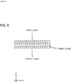
- FIG. 6 schematically shows a cross section of an optical article which was such manufactured.
- the periodical refractive index distribution corresponding to the two-dimensional array of the micromirrors is generated in each of the cured layers of the optical article, the refractive index distributions in adjacent cured layers do not overlap in the X-Y plane with each other.
- a light enters this optical article along the direction of cured layer stacking and diffracted light is generated, it is possible to hold down the intensity of the first-order diffracted light equal to or less than 6% of that of the zero-order light. Therefore, the optical article with high optical performance is obtained.
- the optical shaping apparatus 300 does not equip the diffusion element 8.
- the optical shaping apparatus 300 may equip the diffusion element.
- the optical article manufactured by using the optical shaping apparatus 300 which equips the diffusion element can hold down the generation of the diffracted light more effectively. It is to be noted that, changing rates of the projection magnification of the image of the micromirrors and the irradiation area are determined according to required optical performance to the optical article.
- the distance of moving the stage 4 to the positive direction of the Z-axis is constant after the completion of forming each of the cured layers.
- thickness of each of the cured layers of the optical article manufactured in each of the above described embodiments is constant.
- the diffracted light is generated as shown in FIG. 9 .
- a method for preventing generation of the diffracted light even in such case will be explained as follows.
- an optical article is manufactured by using the optical shaping apparatus 100 from which the diffusion element 8 is removed.
- the procedure of manufacturing the optical article in the present embodiment will be explained below.
- the processes of emitting light from the light source 1, forming the desired shape of the output light flux by reflecting the emitted light by the micromirror device 3 and passing through the light flux by the projection optical system 6 to converge it are substantially the same as processes of the first embodiment, therefore, explanation of these processes are omitted here.
- the output light flux, after being converged by the projection optical system 6, irradiates the light-curable resin which is filled in the clearance between the stage 4 and the bottom portion of the container 2.
- the light-curable resin in the portion corresponding to the irradiation area is cured and forms a first cured layer.
- the thickness of this clearance of this time namely the distance between the surface of the stage 4 and the bottom portion of the container of this time is defined as a first distance. Therefore, the thickness of the first cured layer corresponds to the first distance.
- the control unit 7 stops outputting of the ultraviolet light from the light source 1 and controls the stage driving mechanism 5 so that the stage 4 moves predetermined distance to the positive direction of the Z-axis (to the first direction) and then stops.
- the moving distance (rising distance) of this time of the stage 4 is defined as a second distance.
- the second distance is set to be different from the first distance.
- the first cured layer adheres to the stage 4 and rises with the stage 4. In consequence, a clearance corresponding to the second distance is generated between the first cured layer and the bottom portion of the container 2, and the light-curable resin is filled in this clearance.
- the control unit 7 controls the direction of the reflective surface of each of the micromirrors of the micromirror device 3 to set the desired shape of the output light flux again.
- the control unit 7 lets the light source 1 emit the ultraviolet light toward the micromirror device 3, thereby a second cured layer is laminated on the first cured layer. As described above, because the second distance is different from the first distance, the thickness of the second cured layer is different from that of the first cured layer.
- the control unit 7 stops outputting of the ultraviolet light from the light source 1 and controls the stage driving mechanism 5 so that the stage 4 moves predetermined distance to the positive direction of the Z-axis (to the first direction) and then stops.
- the moving distance of this time of the stage 4 is defined as a third distance.
- the third distance is set to be different from the second distance.
- the second cured layer is laminated on the first cured layer, and these laminated layers raise with stage 4. In consequence, a clearance corresponding to the third distance is generated between the second cured layer and the bottom portion of the container 2, and the light-curable resin is filled in this clearance.
- the control unit 7 controls the direction of the reflective surface of the each of the micromirrors of the micromirror device 3 to set the desired shape of the output light flux again.
- the control unit 7 lets the light source 1 emit the ultraviolet light toward the micromirror device 3, thereby a third cured layer is laminated on the second cured layer. Because the third distance is different from the second distance, the thickness of the third cured layer is different from that of the second cured layer.
- control unit 7 controls the stage driving mechanism 5 so as to set the moving distance to raise the stage 4 to a value different from the value which was set in the previous setting, and cured layers are formed sequentially, thereby the optical article is manufactured.
- the moving distances are set randomized so as to have an appropriate deviation.
- the thicknesses of the cured layers of the optical article also have an appropriate deviation.
- FIG. 7 schematically shows a cross section of an optical article which was such manufactured.
- FIG. 7 there is an appropriate deviation in the thicknesses of the cured layers of the optical article.
- a light enters this optical article along the direction of the surface of the cured-layers and diffracted light is generated, it is possible to hold down the intensity of the first-order diffracted light equal to or less than 6% of that of the zero-order light. Therefore, the optical article with high optical performance is obtained.
- An average and a deviation of the moving distances can be set randomized based on a portional shape of the optical article. For instance, when forming cured layers corresponding to a portion at which shape greatly changes, the moving distances of the stage 4 are set randomized so that the average of them is relatively small and the standard deviation of them is relatively large. Thereby, it is possible to form such portion with a smooth surface. In contrast, when forming cured layers corresponding to a portion at which shape does not change greatly, the moving distances of the stage 4 are set randomized so that the average of them is relatively large and the standard deviation of them is relatively small. Thereby, it is possible to form such portion efficiently.
- the moving distances of the stage 4 can be set randomized based on the required optical performance to each of the domains. For instance, when forming cured layers corresponding to a domain of the optical article to which very high optical performance is required, the moving distances of the stage 4 are set randomized so that the standard deviation of them is relatively large. In contrast, when forming cured layers corresponding to a domain of the optical article to which very high optical performance is not required, the moving distances are set randomized so that the standard deviation of them is relatively small.
- Such manufactured optical article has the optical performance especially at the domain to which very high optical performance is required.
- T represents a constant value
- T+ ⁇ k represents the k-th desired distance according to the thickness of the k-th layer
- ⁇ k represents a random value following a probability distribution of the Fourier transform of ⁇ k's probability density function P ⁇ .
- the optical article manufactured by setting the moving distances of the stage 4 randomized as described above has high optical performance.
- a light enters such optical article along the direction of the surface of the cured-layers and diffracted light is generated, it is possible to hold down the intensity of the first-order diffracted light equal to or less than 6% of that of the zero-order light.
- it is possible to suppress a generation of the diffracted light so that the intensity of a first-order diffracted light is equal to or less than 0.01% of that of a zero-order light.
- the diffusion element 8 is not used in the present embodiment as described above. Therefore, in the optical article shown in FIG. 7 , generation of the diffracted light along the direction of cured layer stacking, namely along the direction of the Z-axis, can be reduced by randomization of the moving distances of moving of the stage 4. However, it is not possible to reduce the intensity of diffracted light generated along the direction of the surface of the cured layer, namely along the direction of the X-axis. This is because that the periodical refractive index distribution, corresponding to two-dimensional array of the micromirrors, exists in each cured layer of the optical article. In regard to this point, by using the optical shaping apparatus equipped with the diffusion element 8 as same as the optical shaping apparatus 100 shown in FIG.
- the optical article that generation of the diffracted light is reduced so that the intensity of a first-order diffracted light is equal to or less than 5% or 3% or even 0.01% of that of a zero-order light. It can be determined whether or not the diffusion element 8 is used based on the required optical performance to the optical article to be manufactured.
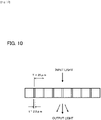
- FIG. 10 is a schematic diagram showing a model used for the simulation.
- this model has a structure in which unit cells are periodically arranged in cycle length T of 25 ⁇ m, and a space whose width t is 2.5 ⁇ m is arranged between each of unit cells.
- this model has a structure of the light-curable resin in which the spaces of 2.5 ⁇ m width are formed in each 25 ⁇ m interval.
- the structure in which light-curable resin and a space (air) are periodically arranged corresponds to the reticulated periodical refractive index distribution.
- FIG. 11 is a schematic diagram of a model used for the simulation.
- This model corresponds to, for example, an optical article manufactured by setting the moving distances of the stage 4 randomized. Comparing with the model shown in FIG. 10 which has a basic structure in which the spaces of width t are formed in each interval of cycle length T, the model shown in FIG. 11 differs from that positions of the spaces of width t are deviated from those of the positions of the model shown in FIG. 10 . In other words, each of the cycle lengths T are randomized. It should be noted that, in FIG. 11 , the portion shown by dotted lines represents the model shown in FIG. 10 in purpose of comparison.
- this model is constructed so that the position of the center of the k-th unit cell is deviated in randomized distance ⁇ k from the position of that in the basic model shown in FIG. 10 .
- P ⁇ ( ⁇ ) represents the probability density function and U without randomization represents the diffraction efficiency of the basic structure model (without adopting randomization). If ⁇ k distributes uniformly in the range of [- ⁇ /2, ⁇ / 2], the diffraction efficiency of the model is expressed by next expression (5).
- P ⁇ ( ⁇ ) sinc( ⁇ ).
- the micromirror device 3 is used as the output setting element, and the output light flux in desired shape is formed by letting the micromirror device 3 reflect the ultraviolet light emitted from the light source.
- the output setting element not only reflection type devices like a micromirror device 3 but also transmission type devices like a transmissive liquid crystal device can be used as the output setting element.
Landscapes
- Engineering & Computer Science (AREA)
- Chemical & Material Sciences (AREA)
- Materials Engineering (AREA)
- Manufacturing & Machinery (AREA)
- Physics & Mathematics (AREA)
- Mechanical Engineering (AREA)
- Optics & Photonics (AREA)
- Health & Medical Sciences (AREA)
- Toxicology (AREA)
- General Physics & Mathematics (AREA)
- Ophthalmology & Optometry (AREA)
- Microelectronics & Electronic Packaging (AREA)
Claims (15)
- Procédé destiné à fabriquer un article optique comprenant :un processus de génération d'un flux de lumière de sortie consistant à générer un flux de lumière de sortie en entrant une lumière que propage une source de lumière (1) dans un élément de réglage de sortie (3) ayant une structure de répétition qui génère une forme souhaitée d'une zone de sortie et à maintenir la forme souhaitée de la zone de sortie pendant une période souhaitée ;un processus de formation d'une couche durcie consistant à former une couche durcie au niveau d'une zone d'irradiation qui est formée en correspondance avec la zone de sortie en introduisant le flux de lumière de sortie à travers un système optique de projection (6) dans un contenant (2) dans lequel est contenue une résine qui durcit à la lumière dans un état liquide et dans lequel est agencé un plateau (4) et à condenser le flux de lumière de sortie ; etun processus de déplacement du plateau dans une première direction, consistant à déplacer le plateau (4) d'une distance souhaitée le long de la première direction de propagation du flux de sortie, dans lequelle processus de génération d'un flux de lumière de sortie, le processus de formation d'une couche durcie et le processus de déplacement du plateau dans une première direction sont exécutés séquentiellement dans cet ordre, en formant de ce fait l'article optique dans une structure de répétition sur la surface du plateau (4), et dans lequelle procédé comprend en outre un processus de variation d'irradiation qui réduit l'effet de diffraction en réduisant le contraste d'une distribution d'indice de réfraction périodique qui provient de la structure de répétition dans l'article optique.
- Procédé destiné à fabriquer un article optique selon la revendication 1, dans lequel :
le processus de variation d'irradiation est exécuté grâce à l'un au moins de :une diffusion du flux de lumière de sortie en faisant passer le flux de lumière de sortie à travers un élément de diffusion (8) sous un angle de diffusion compris entre 5 et 25 degrés qui est agencé au niveau du contenant (2) ou à proximité du contenant (2) ;un déplacement du plateau dans une seconde direction en déplaçant le plateau (4) dans une seconde direction qui est perpendiculaire à la première direction dans le processus de génération d'une couche durcie ;un réglage de la position de condensation de telle sorte que la position de condensation du flux de lumière de sortie réglée par le système optique de projection (6) dévie de la position où doit être formée la couche durcie ;une variation du grossissement en faisant varier le grossissement du système optique de projection (6) dans chacun des processus de génération d'une couche durcie ; etun réglage de la distance de déplacement dans la première direction dans le processus de déplacement du plateau dans la première direction en réglant au moins deux valeurs différentes. - Procédé destiné à fabriquer un article optique selon la revendication 1 ou 2, dans lequel :l'élément de réglage de sortie (3) est un dispositif à micromiroirs qui comprend une pluralité de micromiroirs, la surface de réflexion de chacun des micromiroirs pouvant être réglée individuellement ;la forme souhaitée de la zone de sortie est générée en commandant la surface de réflexion de chacun des micromiroirs ;le flux de lumière de sortie est un flux de lumière réfléchie qui est réfléchi au niveau de la zone de sortie du dispositif à micromiroirs ; etune image de surface selon la zone de sortie du dispositif à micromiroirs est formée au niveau de la zone d'irradiation.
- Procédé destiné à fabriquer un article optique selon la revendication 2, dans lequel
l'angle de diffusion du flux de lumière de sortie qui est passé à travers l'élément de diffusion (8) est un angle de diffusion compris entre 8 et 12 degrés. - Procédé destiné à fabriquer un composant optique selon l'une quelconque des revendications 1 à 4, dans lequel
la distance souhaitée à régler pour le processus de déplacement du plateau dans la première direction, présente au moins deux valeurs différentes. - Procédé destiné à fabriquer un article optique selon l'une quelconque des revendications 1 à 4, dans lequel
la distance souhaitée à régler pour le processus de déplacement du plateau dans la première direction est randomisée. - Procédé destiné à fabriquer un article optique selon la revendication 6, dans lequel
la distance souhaitée à régler pour le processus de déplacement du plateau dans la première direction est randomisée et satisfait à l'expression suivante :
- Appareil de mise en forme optique (100) comprenant :une source de lumière (1) ;un contenant (2) qui contient une résine qui durcit à la lumière ;un élément de réglage de sortie (3) ayant une structure de répétition qui reçoit une lumière que propage la source de lumière (1) et qui règle la sortie du flux de lumière de sortie vers le contenant (2) ;un plateau (4) qui est agencé dans le contenant (2), mobile le long d'une première direction de propagation du flux de sortie, et une couche durcie générée par le durcissement de la résine qui durcit à la lumière est formée sur une surface de celui-ci ;un mécanisme d'entraînement du plateau (5) qui entraîne le plateau (4) ;un système optique de projection (6) qui forme une zone d'irradiation en condensant et en introduisant le flux de lumière de sortie dans le contenant (2) ; etune première unité de commande, dans laquellel'élément de réglage de sortie (3) peut générer une forme souhaitée d'une zone de sortie et maintenir la forme souhaitée de la zone de sortie pendant une période souhaitée,la première unité de commande exécute :une première commande qui exécute une commande de l'élément de réglage de sortie (3) pour générer une forme souhaitée de la zone de sortie et maintenir la forme souhaitée de la zone de sortie pendant une période souhaitée ; etune deuxième commande qui exécute une commande du mécanisme d'entraînement du plateau (5) pour déplacer le plateau (4) d'une distance souhaitée dans la première direction après l'écoulement de la période souhaitée, etl'appareil de mise en forme optique (100) comprend en outre un dispositif de variation d'irradiation qui réduit l'effet de diffraction qui provient de la répétition dans la formation de l'article optique.
- Appareil de mise en forme optique (100) selon la revendication 8, dans lequel le dispositif de variation d'irradiation comprend l'un au moins de :un élément de diffusion (8) qui diffuse le flux de lumière de sortie sous un angle de diffusion compris entre 5 et 25 degrés agencé au niveau du contenant (2) ou au niveau d'une position égale ou inférieure à 5 mm à partir d'une surface du contenant (2),une deuxième unité de commande qui commande un déplacement du plateau (4) dans une seconde direction qui est perpendiculaire à la première direction ;une troisième unité de commande qui commande une modification de la position de condensation du système optique de projection (6) ;une quatrième unité de commande qui commande une modification du grossissement du système optique de projection (6) ; etune cinquième unité de commande qui commande le réglage de la distance souhaitée selon deux valeurs différentes au moins dans la deuxième commande.
- Appareil de mise en forme optique (100) selon la revendication 8 ou 9, dans lequell'élément de réglage de sortie (3) est un dispositif à micromiroirs qui comprend une pluralité de micromiroirs, la surface de réflexion de chacun des micromiroirs pouvant être réglée individuellement ;la forme souhaitée de la zone de sortie est générée en commandant la surface de réflexion de chacun des micromiroirs ;le flux de lumière de sortie est un flux de lumière réfléchie qui est réfléchi au niveau de la zone de sortie du dispositif à micromiroirs ; etune image de surface selon la zone de sortie du dispositif à micromiroirs est formée au niveau de la zone d'irradiation.
- Appareil de mise en forme optique (100) selon la revendication 9, dans lequel
l'élément de diffusion (8) diffuse le flux de lumière de sortie sous un angle de diffusion compris entre 8 et 12 degrés et est agencé au niveau du contenant (2) ou au niveau d'une position égale ou inférieure à 1 mm à partir d'une surface du contenant (2). - Appareil de mise en forme optique (100) selon l'une quelconque des revendications 8 à 11, dans lequel
la première unité de commande exécute les commandes de façon à exécuter la première commande et la deuxième commande à plusieurs reprises à la suite. - Appareil de mise en forme optique (100) selon l'une quelconque des revendications 8 à 11, dans lequel
la première unité de commande exécute la deuxième commande afin de régler la distance souhaitée randomisée. - Article optique fabriqué avec le procédé selon l'une quelconque des revendications 1 à 7, dans lequel
quand une lumière est incidente sur l'article optique, une lumière du premier ordre générée par diffraction est égale ou inférieure à 6 % d'une lumière d'ordre zéro. - Article optique selon la revendication 14, dans lequel l'article optique est une lentille.
Applications Claiming Priority (1)
| Application Number | Priority Date | Filing Date | Title |
|---|---|---|---|
| PCT/JP2017/022918 WO2018235209A1 (fr) | 2017-06-21 | 2017-06-21 | Procédé de fabrication d'article optique et appareil de modelage optique |
Publications (2)
| Publication Number | Publication Date |
|---|---|
| EP3642663A1 EP3642663A1 (fr) | 2020-04-29 |
| EP3642663B1 true EP3642663B1 (fr) | 2023-01-04 |
Family
ID=59298497
Family Applications (1)
| Application Number | Title | Priority Date | Filing Date |
|---|---|---|---|
| EP17737384.2A Active EP3642663B1 (fr) | 2017-06-21 | 2017-06-21 | Procédé de fabrication d'article optique et appareil de modelage optique |
Country Status (5)
| Country | Link |
|---|---|
| US (1) | US11390017B2 (fr) |
| EP (1) | EP3642663B1 (fr) |
| JP (1) | JP6972186B2 (fr) |
| CN (1) | CN110770626B (fr) |
| WO (1) | WO2018235209A1 (fr) |
Families Citing this family (9)
| Publication number | Priority date | Publication date | Assignee | Title |
|---|---|---|---|---|
| JP2020529936A (ja) * | 2017-08-02 | 2020-10-15 | トリオ ラブズ インコーポレイテッドTrio Labs, Inc. | in situ注入およびイメージングを用いる立体自由造形 |
| ES2916577T3 (es) * | 2019-02-27 | 2022-07-01 | Ivoclar Vivadent Ag | Dispositivo de estereolitografía y un procedimiento para ajustar un dispositivo de estereolitografía |
| US11633907B2 (en) * | 2020-10-16 | 2023-04-25 | Indizen Optical Technologies S.L. | Eyewear lens creation using additive techniques with diffuse light |
| US20230417963A1 (en) * | 2020-12-22 | 2023-12-28 | Fujikura Ltd. | Method for manufacturing optical computation device, optical diffraction unit intermediate, and optical computation device |
| EP4119329A1 (fr) | 2021-07-12 | 2023-01-18 | Essilor International | Procédé de fabrication additive d'un dispositif ophtalmique et système de fabrication configuré pour mettre en uvre un tel procédé |
| EP4344862A1 (fr) | 2022-09-30 | 2024-04-03 | Essilor International | Procédé de fabrication additive d'un dispositif ophtalmique et système de fabrication conçu pour mettre en uvre un tel procédé |
| AU2023382064A1 (en) * | 2022-11-15 | 2025-05-29 | Zydex Pty Ltd | Apparatus and method for making a stereolithographic |
| EP4385708A1 (fr) | 2022-12-13 | 2024-06-19 | Essilor International | Procédé de fabrication additive d'un dispositif ophtalmique et système de fabrication conçu pour mettre en uvre un tel procédé |
| US20260061701A1 (en) * | 2024-08-28 | 2026-03-05 | Indizen Optical Technologies S.L. | Eyewear lens creation by additive manufacturing using improved light pattern techniques |
Family Cites Families (28)
| Publication number | Priority date | Publication date | Assignee | Title |
|---|---|---|---|---|
| JPH08192469A (ja) * | 1995-01-20 | 1996-07-30 | Ushio Inc | 光硬化性樹脂の硬化装置 |
| WO2001005575A1 (fr) * | 1999-07-15 | 2001-01-25 | Edward Jefferson Horne | Procede et dispositif de production pour matiere formee polymerisable |
| JP2004061993A (ja) * | 2002-07-31 | 2004-02-26 | Olympus Corp | 光学装置 |
| JP3989412B2 (ja) * | 2002-10-21 | 2007-10-10 | オリンパス株式会社 | 照明装置及び画像投影装置 |
| JP2004325647A (ja) * | 2003-04-23 | 2004-11-18 | Sharp Corp | 表示素子 |
| JP2007121611A (ja) * | 2005-10-27 | 2007-05-17 | Sony Corp | ズームレンズ及び撮像装置 |
| US8451427B2 (en) * | 2007-09-14 | 2013-05-28 | Nikon Corporation | Illumination optical system, exposure apparatus, optical element and manufacturing method thereof, and device manufacturing method |
| JP2009129502A (ja) * | 2007-11-22 | 2009-06-11 | Sony Corp | 光ピックアップ及び光ディスク装置 |
| WO2009087805A1 (fr) * | 2008-01-11 | 2009-07-16 | Nikon Corporation | Modulateur spatial de lumière, système optique d'éclairage, dispositif d'alignement et procédé de fabrication de dispositif |
| CN101650446A (zh) * | 2009-09-08 | 2010-02-17 | 南昌航空大学 | 二元光学组件横向制作方法 |
| TW201222009A (en) * | 2010-05-21 | 2012-06-01 | Corning Inc | Systems and methods for reducing speckle using diffusing surfaces |
| US8351106B2 (en) * | 2010-07-13 | 2013-01-08 | Iowa State University Research Foundation, Inc. | Elastomeric device for tunable imaging |
| FR2972814B1 (fr) * | 2011-03-16 | 2014-04-18 | Essilor Int | Element optique transparent a plusieurs couches constituees de pavages cellulaires |
| JP2013054248A (ja) * | 2011-09-05 | 2013-03-21 | Sony Corp | 光学素子およびその形成方法、光学素子アレイ、表示装置、電子機器 |
| DE102012224005B4 (de) * | 2012-12-20 | 2015-07-23 | Heraeus Kulzer Gmbh | Verfahren zur Herstellung einer homogenen Lichtverteilung |
| JP6120611B2 (ja) * | 2013-02-27 | 2017-04-26 | 日立マクセル株式会社 | ビーム走査型表示装置 |
| JP6190599B2 (ja) | 2013-03-08 | 2017-08-30 | Kyb株式会社 | バスバーユニットの製造方法 |
| DE102013209829B4 (de) * | 2013-05-27 | 2016-04-28 | Fraunhofer-Gesellschaft zur Förderung der angewandten Forschung e.V. | Optische Struktur mit daran angeordneten Stegen und Verfahren zur Herstellung derselben |
| DE102013209823B4 (de) * | 2013-05-27 | 2015-10-08 | Fraunhofer-Gesellschaft zur Förderung der angewandten Forschung e.V. | Optische Struktur mit daran angeordneten Stegen und Verfahren zur Herstellung derselben |
| EP3027397B1 (fr) * | 2013-07-31 | 2021-07-14 | Essilor International | Procédé additif de fabrication de lentille ophtalmique transparente |
| ITVI20130229A1 (it) * | 2013-09-18 | 2015-03-19 | Ettore Maurizio Costabeber | Macchina stereolitografica con gruppo ottico perfezionato |
| WO2015072921A1 (fr) | 2013-11-14 | 2015-05-21 | Structo Pte. Ltd | Dispositif et procédé de fabrication additive |
| WO2015081756A1 (fr) * | 2013-12-03 | 2015-06-11 | 上海普利生机电科技有限公司 | Dispositif d'impression 3d à photodurcissement et son système d'imagerie |
| GB2522082B (en) * | 2014-03-14 | 2016-02-24 | Oclaro Technology Ltd | Optical component |
| US9952448B2 (en) * | 2014-03-26 | 2018-04-24 | Indizen Optical Technologies, S.L. | Eyewear lens production by additive techniques |
| CN104626586B (zh) * | 2015-01-28 | 2017-05-03 | 东莞理工学院 | 基于dmd的光固化成型方法 |
| US10401603B2 (en) * | 2015-09-21 | 2019-09-03 | The Chinese University Of Hong Kong | High-speed binary laser beam shaping and scanning |
| JP6889155B2 (ja) * | 2015-09-25 | 2021-06-18 | カーボン,インコーポレイテッド | ライティングパネルを有する継続的液体相間印刷用のビルドプレートアセンブリー、及び関連した方法、システム並びにデバイス |
-
2017
- 2017-06-21 EP EP17737384.2A patent/EP3642663B1/fr active Active
- 2017-06-21 CN CN201780092329.7A patent/CN110770626B/zh active Active
- 2017-06-21 US US16/618,391 patent/US11390017B2/en active Active
- 2017-06-21 WO PCT/JP2017/022918 patent/WO2018235209A1/fr not_active Ceased
- 2017-06-21 JP JP2019571080A patent/JP6972186B2/ja active Active
Also Published As
| Publication number | Publication date |
|---|---|
| EP3642663A1 (fr) | 2020-04-29 |
| JP2020524623A (ja) | 2020-08-20 |
| US20200290268A1 (en) | 2020-09-17 |
| CN110770626A (zh) | 2020-02-07 |
| JP6972186B2 (ja) | 2021-11-24 |
| CN110770626B (zh) | 2022-04-01 |
| WO2018235209A1 (fr) | 2018-12-27 |
| US11390017B2 (en) | 2022-07-19 |
Similar Documents
| Publication | Publication Date | Title |
|---|---|---|
| US11390017B2 (en) | Method of manufacturing optical article and optical shaping apparatus | |
| CN110651204B (zh) | 具有可变衍射效率的衍射光栅和用于显示图像的方法 | |
| CN103080843B (zh) | 用于印刷具有大焦深的周期图案的方法和设备 | |
| TWI588615B (zh) | 照明光學系統、曝光裝置及元件製造方法 | |
| CN103676461B (zh) | 波束成形器、退火系统、热处理法和半导体装置制造方法 | |
| JP4422610B2 (ja) | 光学基板及び製造法 | |
| JP7297548B2 (ja) | 導光板の製造方法、導光板モジュールの製造方法、および画像表示装置の製造方法 | |
| US20200150430A1 (en) | Light guide plate and image display device | |
| JP2005234538A (ja) | ディスプレイ用光学フィルム | |
| JP2008525850A (ja) | 光学的基板及びその製造方法 | |
| TWI581008B (zh) | 縮放結構光圖案的方法以及應用該方法的光學裝置 | |
| WO2016163125A1 (fr) | Plaque de diffusion composite | |
| JP2020008599A (ja) | 導光板、導光板モジュール、画像表示装置および導光板の製造方法 | |
| WO2013164997A1 (fr) | Procédé permettant d'évaluer et d'améliorer la distribution de luminance de pupille, système optique d'éclairage et son procédé de réglage, dispositif d'exposition, procédé d'exposition et procédé de fabrication de dispositif | |
| Emami et al. | An improved vat photopolymerization cure model demonstrates photobleaching effects | |
| KR20140120697A (ko) | Glv를 이용한 디지털 노광기 및 dmd를 이용한 디지털 노광기 | |
| Shen et al. | High-power excimer laser homogenization using dual-microlens arrays | |
| Hur | Maskless fabrication of three-dimensional microstructures with high isotropic resolution: practical and theoretical considerations | |
| KR20250113418A (ko) | 더미 임프린팅된 구역들 | |
| JP2013165134A (ja) | 瞳輝度分布の最適化方法、照明光学系およびその調整方法、露光装置、並びにデバイス製造方法 | |
| JP2014123600A (ja) | オプティカルインテグレータ、照明ユニット、伝送光学系、照明光学系、露光装置、およびデバイス製造方法 | |
| JP2014066818A (ja) | 露光装置、露光方法及びマイクロデバイス | |
| KR102404151B1 (ko) | 조명 광학계, 노광 장치 및 물품 제조 방법 | |
| JP6183635B2 (ja) | オプティカルインテグレータ、照明ユニット、伝送光学系、照明光学系、露光装置、およびデバイス製造方法 | |
| JP2014107309A (ja) | 伝送光学系、照明光学系、露光装置、およびデバイス製造方法 |
Legal Events
| Date | Code | Title | Description |
|---|---|---|---|
| STAA | Information on the status of an ep patent application or granted ep patent |
Free format text: STATUS: UNKNOWN |
|
| STAA | Information on the status of an ep patent application or granted ep patent |
Free format text: STATUS: THE INTERNATIONAL PUBLICATION HAS BEEN MADE |
|
| PUAI | Public reference made under article 153(3) epc to a published international application that has entered the european phase |
Free format text: ORIGINAL CODE: 0009012 |
|
| STAA | Information on the status of an ep patent application or granted ep patent |
Free format text: STATUS: REQUEST FOR EXAMINATION WAS MADE |
|
| 17P | Request for examination filed |
Effective date: 20191127 |
|
| AK | Designated contracting states |
Kind code of ref document: A1 Designated state(s): AL AT BE BG CH CY CZ DE DK EE ES FI FR GB GR HR HU IE IS IT LI LT LU LV MC MK MT NL NO PL PT RO RS SE SI SK SM TR |
|
| AX | Request for extension of the european patent |
Extension state: BA ME |
|
| DAV | Request for validation of the european patent (deleted) | ||
| DAX | Request for extension of the european patent (deleted) | ||
| GRAP | Despatch of communication of intention to grant a patent |
Free format text: ORIGINAL CODE: EPIDOSNIGR1 |
|
| STAA | Information on the status of an ep patent application or granted ep patent |
Free format text: STATUS: GRANT OF PATENT IS INTENDED |
|
| INTG | Intention to grant announced |
Effective date: 20220819 |
|
| GRAS | Grant fee paid |
Free format text: ORIGINAL CODE: EPIDOSNIGR3 |
|
| GRAA | (expected) grant |
Free format text: ORIGINAL CODE: 0009210 |
|
| STAA | Information on the status of an ep patent application or granted ep patent |
Free format text: STATUS: THE PATENT HAS BEEN GRANTED |
|
| AK | Designated contracting states |
Kind code of ref document: B1 Designated state(s): AL AT BE BG CH CY CZ DE DK EE ES FI FR GB GR HR HU IE IS IT LI LT LU LV MC MK MT NL NO PL PT RO RS SE SI SK SM TR |
|
| REG | Reference to a national code |
Ref country code: GB Ref legal event code: FG4D |
|
| REG | Reference to a national code |
Ref country code: DE Ref legal event code: R096 Ref document number: 602017065205 Country of ref document: DE |
|
| REG | Reference to a national code |
Ref country code: CH Ref legal event code: EP |
|
| REG | Reference to a national code |
Ref country code: AT Ref legal event code: REF Ref document number: 1542366 Country of ref document: AT Kind code of ref document: T Effective date: 20230115 |
|
| REG | Reference to a national code |
Ref country code: IE Ref legal event code: FG4D |
|
| REG | Reference to a national code |
Ref country code: LT Ref legal event code: MG9D |
|
| REG | Reference to a national code |
Ref country code: NL Ref legal event code: MP Effective date: 20230104 |
|
| REG | Reference to a national code |
Ref country code: AT Ref legal event code: MK05 Ref document number: 1542366 Country of ref document: AT Kind code of ref document: T Effective date: 20230104 |
|
| PG25 | Lapsed in a contracting state [announced via postgrant information from national office to epo] |
Ref country code: NL Free format text: LAPSE BECAUSE OF FAILURE TO SUBMIT A TRANSLATION OF THE DESCRIPTION OR TO PAY THE FEE WITHIN THE PRESCRIBED TIME-LIMIT Effective date: 20230104 |
|
| PG25 | Lapsed in a contracting state [announced via postgrant information from national office to epo] |
Ref country code: RS Free format text: LAPSE BECAUSE OF FAILURE TO SUBMIT A TRANSLATION OF THE DESCRIPTION OR TO PAY THE FEE WITHIN THE PRESCRIBED TIME-LIMIT Effective date: 20230104 Ref country code: PT Free format text: LAPSE BECAUSE OF FAILURE TO SUBMIT A TRANSLATION OF THE DESCRIPTION OR TO PAY THE FEE WITHIN THE PRESCRIBED TIME-LIMIT Effective date: 20230504 Ref country code: NO Free format text: LAPSE BECAUSE OF FAILURE TO SUBMIT A TRANSLATION OF THE DESCRIPTION OR TO PAY THE FEE WITHIN THE PRESCRIBED TIME-LIMIT Effective date: 20230404 Ref country code: LV Free format text: LAPSE BECAUSE OF FAILURE TO SUBMIT A TRANSLATION OF THE DESCRIPTION OR TO PAY THE FEE WITHIN THE PRESCRIBED TIME-LIMIT Effective date: 20230104 Ref country code: LT Free format text: LAPSE BECAUSE OF FAILURE TO SUBMIT A TRANSLATION OF THE DESCRIPTION OR TO PAY THE FEE WITHIN THE PRESCRIBED TIME-LIMIT Effective date: 20230104 Ref country code: HR Free format text: LAPSE BECAUSE OF FAILURE TO SUBMIT A TRANSLATION OF THE DESCRIPTION OR TO PAY THE FEE WITHIN THE PRESCRIBED TIME-LIMIT Effective date: 20230104 Ref country code: ES Free format text: LAPSE BECAUSE OF FAILURE TO SUBMIT A TRANSLATION OF THE DESCRIPTION OR TO PAY THE FEE WITHIN THE PRESCRIBED TIME-LIMIT Effective date: 20230104 Ref country code: AT Free format text: LAPSE BECAUSE OF FAILURE TO SUBMIT A TRANSLATION OF THE DESCRIPTION OR TO PAY THE FEE WITHIN THE PRESCRIBED TIME-LIMIT Effective date: 20230104 |
|
| PG25 | Lapsed in a contracting state [announced via postgrant information from national office to epo] |
Ref country code: SE Free format text: LAPSE BECAUSE OF FAILURE TO SUBMIT A TRANSLATION OF THE DESCRIPTION OR TO PAY THE FEE WITHIN THE PRESCRIBED TIME-LIMIT Effective date: 20230104 Ref country code: PL Free format text: LAPSE BECAUSE OF FAILURE TO SUBMIT A TRANSLATION OF THE DESCRIPTION OR TO PAY THE FEE WITHIN THE PRESCRIBED TIME-LIMIT Effective date: 20230104 Ref country code: IS Free format text: LAPSE BECAUSE OF FAILURE TO SUBMIT A TRANSLATION OF THE DESCRIPTION OR TO PAY THE FEE WITHIN THE PRESCRIBED TIME-LIMIT Effective date: 20230504 Ref country code: GR Free format text: LAPSE BECAUSE OF FAILURE TO SUBMIT A TRANSLATION OF THE DESCRIPTION OR TO PAY THE FEE WITHIN THE PRESCRIBED TIME-LIMIT Effective date: 20230405 Ref country code: FI Free format text: LAPSE BECAUSE OF FAILURE TO SUBMIT A TRANSLATION OF THE DESCRIPTION OR TO PAY THE FEE WITHIN THE PRESCRIBED TIME-LIMIT Effective date: 20230104 |
|
| P01 | Opt-out of the competence of the unified patent court (upc) registered |
Effective date: 20230728 |
|
| REG | Reference to a national code |
Ref country code: DE Ref legal event code: R097 Ref document number: 602017065205 Country of ref document: DE |
|
| PG25 | Lapsed in a contracting state [announced via postgrant information from national office to epo] |
Ref country code: SM Free format text: LAPSE BECAUSE OF FAILURE TO SUBMIT A TRANSLATION OF THE DESCRIPTION OR TO PAY THE FEE WITHIN THE PRESCRIBED TIME-LIMIT Effective date: 20230104 Ref country code: RO Free format text: LAPSE BECAUSE OF FAILURE TO SUBMIT A TRANSLATION OF THE DESCRIPTION OR TO PAY THE FEE WITHIN THE PRESCRIBED TIME-LIMIT Effective date: 20230104 Ref country code: EE Free format text: LAPSE BECAUSE OF FAILURE TO SUBMIT A TRANSLATION OF THE DESCRIPTION OR TO PAY THE FEE WITHIN THE PRESCRIBED TIME-LIMIT Effective date: 20230104 Ref country code: DK Free format text: LAPSE BECAUSE OF FAILURE TO SUBMIT A TRANSLATION OF THE DESCRIPTION OR TO PAY THE FEE WITHIN THE PRESCRIBED TIME-LIMIT Effective date: 20230104 Ref country code: CZ Free format text: LAPSE BECAUSE OF FAILURE TO SUBMIT A TRANSLATION OF THE DESCRIPTION OR TO PAY THE FEE WITHIN THE PRESCRIBED TIME-LIMIT Effective date: 20230104 |
|
| PLBE | No opposition filed within time limit |
Free format text: ORIGINAL CODE: 0009261 |
|
| STAA | Information on the status of an ep patent application or granted ep patent |
Free format text: STATUS: NO OPPOSITION FILED WITHIN TIME LIMIT |
|
| PG25 | Lapsed in a contracting state [announced via postgrant information from national office to epo] |
Ref country code: SK Free format text: LAPSE BECAUSE OF FAILURE TO SUBMIT A TRANSLATION OF THE DESCRIPTION OR TO PAY THE FEE WITHIN THE PRESCRIBED TIME-LIMIT Effective date: 20230104 |
|
| 26N | No opposition filed |
Effective date: 20231005 |
|
| PG25 | Lapsed in a contracting state [announced via postgrant information from national office to epo] |
Ref country code: MC Free format text: LAPSE BECAUSE OF FAILURE TO SUBMIT A TRANSLATION OF THE DESCRIPTION OR TO PAY THE FEE WITHIN THE PRESCRIBED TIME-LIMIT Effective date: 20230104 |
|
| PG25 | Lapsed in a contracting state [announced via postgrant information from national office to epo] |
Ref country code: SI Free format text: LAPSE BECAUSE OF FAILURE TO SUBMIT A TRANSLATION OF THE DESCRIPTION OR TO PAY THE FEE WITHIN THE PRESCRIBED TIME-LIMIT Effective date: 20230104 Ref country code: MC Free format text: LAPSE BECAUSE OF FAILURE TO SUBMIT A TRANSLATION OF THE DESCRIPTION OR TO PAY THE FEE WITHIN THE PRESCRIBED TIME-LIMIT Effective date: 20230104 |
|
| REG | Reference to a national code |
Ref country code: CH Ref legal event code: PL |
|
| REG | Reference to a national code |
Ref country code: BE Ref legal event code: MM Effective date: 20230630 |
|
| PG25 | Lapsed in a contracting state [announced via postgrant information from national office to epo] |
Ref country code: LU Free format text: LAPSE BECAUSE OF NON-PAYMENT OF DUE FEES Effective date: 20230621 |
|
| REG | Reference to a national code |
Ref country code: IE Ref legal event code: MM4A |
|
| PG25 | Lapsed in a contracting state [announced via postgrant information from national office to epo] |
Ref country code: LU Free format text: LAPSE BECAUSE OF NON-PAYMENT OF DUE FEES Effective date: 20230621 |
|
| PG25 | Lapsed in a contracting state [announced via postgrant information from national office to epo] |
Ref country code: IE Free format text: LAPSE BECAUSE OF NON-PAYMENT OF DUE FEES Effective date: 20230621 |
|
| PG25 | Lapsed in a contracting state [announced via postgrant information from national office to epo] |
Ref country code: IE Free format text: LAPSE BECAUSE OF NON-PAYMENT OF DUE FEES Effective date: 20230621 Ref country code: CH Free format text: LAPSE BECAUSE OF NON-PAYMENT OF DUE FEES Effective date: 20230630 |
|
| PG25 | Lapsed in a contracting state [announced via postgrant information from national office to epo] |
Ref country code: BE Free format text: LAPSE BECAUSE OF NON-PAYMENT OF DUE FEES Effective date: 20230630 |
|
| PG25 | Lapsed in a contracting state [announced via postgrant information from national office to epo] |
Ref country code: BG Free format text: LAPSE BECAUSE OF FAILURE TO SUBMIT A TRANSLATION OF THE DESCRIPTION OR TO PAY THE FEE WITHIN THE PRESCRIBED TIME-LIMIT Effective date: 20230104 |
|
| PG25 | Lapsed in a contracting state [announced via postgrant information from national office to epo] |
Ref country code: BG Free format text: LAPSE BECAUSE OF FAILURE TO SUBMIT A TRANSLATION OF THE DESCRIPTION OR TO PAY THE FEE WITHIN THE PRESCRIBED TIME-LIMIT Effective date: 20230104 |
|
| PGFP | Annual fee paid to national office [announced via postgrant information from national office to epo] |
Ref country code: DE Payment date: 20250522 Year of fee payment: 9 |
|
| PGFP | Annual fee paid to national office [announced via postgrant information from national office to epo] |
Ref country code: GB Payment date: 20250620 Year of fee payment: 9 |
|
| PGFP | Annual fee paid to national office [announced via postgrant information from national office to epo] |
Ref country code: FR Payment date: 20250618 Year of fee payment: 9 |
|
| PG25 | Lapsed in a contracting state [announced via postgrant information from national office to epo] |
Ref country code: CY Free format text: LAPSE BECAUSE OF FAILURE TO SUBMIT A TRANSLATION OF THE DESCRIPTION OR TO PAY THE FEE WITHIN THE PRESCRIBED TIME-LIMIT; INVALID AB INITIO Effective date: 20170621 |
|
| PG25 | Lapsed in a contracting state [announced via postgrant information from national office to epo] |
Ref country code: HU Free format text: LAPSE BECAUSE OF FAILURE TO SUBMIT A TRANSLATION OF THE DESCRIPTION OR TO PAY THE FEE WITHIN THE PRESCRIBED TIME-LIMIT; INVALID AB INITIO Effective date: 20170621 |
|
| PGFP | Annual fee paid to national office [announced via postgrant information from national office to epo] |
Ref country code: IT Payment date: 20250630 Year of fee payment: 9 |
|
| PG25 | Lapsed in a contracting state [announced via postgrant information from national office to epo] |
Ref country code: TR Free format text: LAPSE BECAUSE OF FAILURE TO SUBMIT A TRANSLATION OF THE DESCRIPTION OR TO PAY THE FEE WITHIN THE PRESCRIBED TIME-LIMIT Effective date: 20230104 |