EP3643205A1 - Chaise - Google Patents
Chaise Download PDFInfo
- Publication number
- EP3643205A1 EP3643205A1 EP17914176.7A EP17914176A EP3643205A1 EP 3643205 A1 EP3643205 A1 EP 3643205A1 EP 17914176 A EP17914176 A EP 17914176A EP 3643205 A1 EP3643205 A1 EP 3643205A1
- Authority
- EP
- European Patent Office
- Prior art keywords
- guide
- seat
- tilting
- chair
- guide part
- Prior art date
- Legal status (The legal status is an assumption and is not a legal conclusion. Google has not performed a legal analysis and makes no representation as to the accuracy of the status listed.)
- Granted
Links
Images


Classifications
-
- A—HUMAN NECESSITIES
- A47—FURNITURE; DOMESTIC ARTICLES OR APPLIANCES; COFFEE MILLS; SPICE MILLS; SUCTION CLEANERS IN GENERAL
- A47C—CHAIRS; SOFAS; BEDS
- A47C3/00—Chairs characterised by structural features; Chairs or stools with rotatable or vertically-adjustable seats
- A47C3/02—Rocking chairs
- A47C3/025—Rocking chairs with seat, or seat and back-rest unit, elastically mounted in a rigid frame
- A47C3/026—Rocking chairs with seat, or seat and back-rest unit, elastically mounted in a rigid frame with a central column, e.g. rocking office chairs; Tilting chairs
-
- A—HUMAN NECESSITIES
- A47—FURNITURE; DOMESTIC ARTICLES OR APPLIANCES; COFFEE MILLS; SPICE MILLS; SUCTION CLEANERS IN GENERAL
- A47C—CHAIRS; SOFAS; BEDS
- A47C3/00—Chairs characterised by structural features; Chairs or stools with rotatable or vertically-adjustable seats
- A47C3/02—Rocking chairs
- A47C3/025—Rocking chairs with seat, or seat and back-rest unit, elastically mounted in a rigid frame
- A47C3/0255—Rocking chairs with seat, or seat and back-rest unit, elastically mounted in a rigid frame pivotally mounted in the base frame, e.g. swings
-
- A—HUMAN NECESSITIES
- A47—FURNITURE; DOMESTIC ARTICLES OR APPLIANCES; COFFEE MILLS; SPICE MILLS; SUCTION CLEANERS IN GENERAL
- A47C—CHAIRS; SOFAS; BEDS
- A47C3/00—Chairs characterised by structural features; Chairs or stools with rotatable or vertically-adjustable seats
- A47C3/02—Rocking chairs
- A47C3/025—Rocking chairs with seat, or seat and back-rest unit, elastically mounted in a rigid frame
- A47C3/0257—Rocking chairs with seat, or seat and back-rest unit, elastically mounted in a rigid frame slidingly movable in the base frame, e.g. by rollers
-
- A—HUMAN NECESSITIES
- A47—FURNITURE; DOMESTIC ARTICLES OR APPLIANCES; COFFEE MILLS; SPICE MILLS; SUCTION CLEANERS IN GENERAL
- A47C—CHAIRS; SOFAS; BEDS
- A47C3/00—Chairs characterised by structural features; Chairs or stools with rotatable or vertically-adjustable seats
- A47C3/02—Rocking chairs
- A47C3/03—Locking members
-
- A—HUMAN NECESSITIES
- A47—FURNITURE; DOMESTIC ARTICLES OR APPLIANCES; COFFEE MILLS; SPICE MILLS; SUCTION CLEANERS IN GENERAL
- A47C—CHAIRS; SOFAS; BEDS
- A47C7/00—Parts, details, or accessories of chairs or stools
- A47C7/02—Seat parts
- A47C7/024—Seat parts with double seats
-
- A—HUMAN NECESSITIES
- A47—FURNITURE; DOMESTIC ARTICLES OR APPLIANCES; COFFEE MILLS; SPICE MILLS; SUCTION CLEANERS IN GENERAL
- A47C—CHAIRS; SOFAS; BEDS
- A47C7/00—Parts, details, or accessories of chairs or stools
- A47C7/36—Supports for the head or the back
- A47C7/40—Supports for the head or the back for the back
- A47C7/44—Supports for the head or the back for the back with elastically-mounted frame
- A47C7/448—Supports for the head or the back for the back with elastically-mounted frame with resilient blocks
-
- A—HUMAN NECESSITIES
- A47—FURNITURE; DOMESTIC ARTICLES OR APPLIANCES; COFFEE MILLS; SPICE MILLS; SUCTION CLEANERS IN GENERAL
- A47C—CHAIRS; SOFAS; BEDS
- A47C7/00—Parts, details, or accessories of chairs or stools
- A47C7/002—Chair or stool bases
- A47C7/006—Chair or stool bases with castors
Definitions
- the present invention relates to a chair suitably used at office and the like.
- Patent Document 1 A chair which changes the direction and the angle of the backrest in accordance with the change of a seated person's posture, has conventionally existed.
- Patent Document 1 to 5 A chair which changes the direction and the angle of the backrest in accordance with the change of a seated person's posture, has conventionally existed.
- a chair described in Patent Document No. 1 is configured such that a pair of back plates is each attached to a frame through rubber parts, moves rotationally upward and downward and turns leftward and rightward while compressing the rubber parts and storing repulsion.
- a chair described in Patent Document 2 is configured such that an upper half of the back of automobile sheet turns around the vertical axis while storing repulsion.
- a chair described in Patent Document 3 is configured such that a back and a seat are integrally provided, a lower part of the seat is rollably supported around a fulcrum, and when rolling, the back and the seat compress rubber parts disposed around the lower part of the seat, and the repulsion that the back and the seat return to the reference position, is produced.
- a back and a seat are integrally provided.
- a configuration is enclosed that a part of the back is fixed at fulcrum, and centering around this fulcrum, the back and the seat deform in such a way as to twist leftward and rightward in a front view with the elasticity of the back and the seat in accordance with the movement of a seated person.
- a chair described in Patent Document 5 is configured such that a back and a seat are separated into a plurality of compartments, a part of the back and the seat among the components is partially separated so as to be partially easily deformed, accordingly the area between the compartments is easily twisted and the degree of deformation is increased.
- the back performs a rotating operation so as to twist around a fulcrum and at the same time, the seat deforms. Therefore, when considering the movement of lower body and the movement of upper body, it cannot be said that the movement of the back and the seat matches the movement of the back of the seated person.
- the present invention focuses on these problems, and in view of various movement of the seated person, in order to provide the left-right swinging operation to the seat in non-conventional aspect, an object thereof is to realize a chair wherein a back is capable of performing a new movement suitable for the left-right movement of the seat and returning to the predetermined position when the seated person leaves a seat.
- the present invention adopts the following means to achieve such object.
- a chair according to the present invention wherein the chair is configured such that a back is arranged behind a seat, and the back has an operation mechanism turning-movably supporting the load received from a seated person in a left-right direction in a front view, and when the load is applied, at least a part of guide part of the operation mechanism is separated and the back moves freely, and when the applied load is removed, the back automatically returns to the neutral position along the guide part.
- the back is turning-movable in a front view in a left-right direction, and when the load is applied, at least a part of guide parts of the operation mechanism is separated, and the back moves freely. Therefore, it can be easily adapted to various movement of the seated person. Further, when the seated person leaves a seat, the back reliably returns to the neutral position along guide parts. Therefore, even if the degree of freedom of back movement is increased, a plurality of chairs is easily uniform in appearance when the seated person leaves a seat. Further, it is possible to avoid the situation in that the initial condition of the chair is changed every time the seated person sits on the seat.
- the chair is configured such that a reaction force with which the back returns to the neutral position becomes larger in accordance with an amount of turning movement to both of the left and right directions.
- the back is configured such that a backrest is supported by a back frame via the operation mechanism, the back frame is erected at the rear of the seat, and the backrest is turning-movably attached to the back frame substantially clockwise or counterclockwise direction in a front view via the operation mechanism.
- the back is configured such that a backrest is supported by the back frame via the operation mechanism, and the backrest moves via the operation mechanism having an elastic body toward the rear direction and the turning direction against an elastic reaction force.
- the backrest is configured such that a turning range to the left-right direction becomes larger in accordance with the movement in the rear direction with respect to the back frame.
- the chair is configured such that the seat is swingable in the left-right direction in a front view, and the back performs a left-right turning operation separated from the seat.
- the operation mechanism is provided with a base part and a tilting part, and includes a reference position, a guide part set at the side of the base part and a guide part set at the side of the tilting part are in pressure contact with each other to be guided by the shapes of the guide parts and stopped at the reference position, and when the pressure contact is loosened by the received pressure from the seated person, the base part and the tilting part can be relatively changed from the reference position in accordance with the degree of the received pressure.
- the chair is configured such that the pressure contact of the both guide parts is formed by the elastic body and the elastic body is pressed by the received pressure, whereby the guide part of the tilting part and the guide part of the base part are separated.
- the operation mechanism includes: the base part fixed to the backrest and provided with the elastic body on the back surface side of the base part; the tilting part disposed at a position adjacent to the base part and including a guide part recessed in a tapered shape at the back surface side of the tilting part, the bottom part of the guide part having an opening; and a pressing tool including a guide part having a convex shape corresponding to the guide part of the tilting part on the front surface side of the pressing tool, the pressing tool being fixed to the base part via the opening of the tilting part in a state where the guide part of the pressing tool is fitted into the guide part of the tilting part, and the tilting part is fixed to the received pressure part provided at the upper end part of the back frame.
- one guide part has a substantially partially elliptical mortar-like shape including at least one valley line and the other guide part has a curved shape having at least one ridge line fitted smoothly into the valley line, and the valley line and the ridge line can be fitted into each other.
- one guide part of the both guides are a shaft-shaped part extended upward and downward, or leftward and rightward and the other guide part is a V-groove leading the upper-lower or left-right shaft-shaped member to the center position.
- the base part and the tilting part are provided with engaging parts configured to regulate a relative movement of the base part and the tilting part in collaboration with the guide parts.
- one guide part has three protrusion parts and the other part is in a shape which receives the three protrusion parts, and an elastic body is placed between the one guide part and the other guide part.
- the present invention in view of various movement of a seated person, when giving the left-right swinging operation to the seat in the non- conventional aspect, it is possible to provide a new chair wherein the back can perform a new movement suitable for the left-right movement of the seat and return to the predetermined position when the seated person leaves a seat.
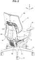
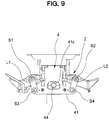
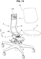
- this chair is an office chair configured by erecting a leg supporting post 13 incorporating a lifting/lowering mechanism therein, in a central part of a leg vane 12 supported by a caster 11, and attaching a support base part 2 rotatably at an upper end side of the leg supporting post 13.
- a seat 5 being a movable part is supported via a front-rear swing part 3 as a one-direction operating part (movable part) operable any one of a front-rear direction (X-direction in the drawings) and a left-right direction (Y-direction in the drawings) being two directions crossing each other, and a left-right swing part 4 being an other-direction operating part (support part) operable in the other of the front-rear direction and the left-right direction and the seat 5 can swing in the front-rear direction and the left-right direction with respect to the support base part 2.
- a front-rear swing part 3 as a one-direction operating part (movable part) operable any one of a front-rear direction (X-direction in the drawings) and a left-right direction (Y-direction in the drawings) being two directions crossing each other
- a left-right swing part 4 being an other-direction operating part (support part) operable in the other of the front-rear direction and the left-right
- the front-rear swing part 3 is provided between the seat 5 and the support base part 2 configured to support the seat 5, and the left-right swing part 4 is provided between the front-rear swing part 3 and the support base part 2. Behind the seat 5, a back 6 is arranged.
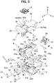
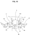
- the support base part 2 functions as a structured body for receiving the load applied by seated person, and in the support base part 2, a left-right pair of arm attachment parts 23 is integrally formed with the support base part 2 via a bearing base part 22 on both left and right sides of a support base main body 21 including a through hole 21a along an up-down direction into which an upper end of the supporting post 13 is inserted.
- a shaft swing damper 21b is attached to the hole 21a opening on the surface of the support base main body 21 in the front-rear direction and upper ends of left-right swing links L1, L2 are attached to holes 22a opening on the front and rear surfaces of the bearing base part 22, via swing support shafts S1, S2.
- the left-right swing part 4 includes a pair of plate-shaped link bases 41 disposed separated from each other in the front-rear direction to perform a swinging operation in the left-right direction with respect to the support base part 2, and a left-right swing main body 42 configured to connect the pair of link bases 41, 41.
- holes 41a, 41a are opened and the lower ends of the left-right swing links L1, L2 are attached via swing shafts S3, S4.
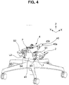
- FIG. 4 illustrates a state where the links L1, L2 are attached via the swing shafts S1 to S4. As illustrated in FIGS.
- the left-right swing main body 42 is provided with a unit attached hole 42a penetrating in the up-down direction, and a later-described left-right lock part 7 is attached to the unit attached hole 42a. That is, the left-right swing main body 42 is disposed in a suspended state to be swingable to the left and right with respect to the support base part 2 via the left-right swing links L1, L2, and the left-right swing links L1, L2 are attached so that the distance between the lower ends is smaller than the distance between the upper ends, as illustrated in FIG. 4 and the like.
- a window 41c is opened at the center of the link base 41, a rolling damper 44 is positioned in the window 41c, and a swing range of the left-right swing part 4 is restricted to a range where the rolling damper 44 can perform a relative movement within the window 41c.
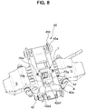
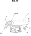
- the front-rear swing part 3 includes a pair of plate-shaped rail plates 31, 31 disposed separated from each other in the left-right direction to perform a swinging operation in the front-rear direction with respect to the left-right swing part 4, and an upper connection plate 32 and a front connection plate 33 configured to connect the pair of rail plates 31, 31.
- a guide hole 34 is provided to penetrate the rail plates 31, a bearing 45a is engaged in the guide hole 34, and the bearing 45a is a rolling body 45 provided to be rollable independently to the left and right on a side surface at a front end side of the left-right swing main body 42.
- the reference sign 45z in the drawings indicates a spacer disposed on an inner surface side of the rail plate 31 and having a diameter larger than that of the bearing 45a.
- the rear end side of the rail plate 31 extends rearward and downward, a lower end of a link arm LA, being a swingable front-rear swing link, is attached via a swing shaft S5 to an extension end of the rail plate 31, and the upper end of the link arm LA is supported by the rear end of the left-right swing body 4 via a swing shaft S6. That is, the rear end of the front-rear swing part 3 is disposed in a suspended state to be swingable forward and rearward with respect to the left-right swing part 4 via the link arm LA.
- the guide hole 34 has a shape that is gently curved forward and downward from the rear end side toward the front end side, and at the rear end, there is provided a shockless part SL configured to mitigate a shock when the front-rear swing part 3 moves forward together with the seat 5.
- the upper connection plate 32 is provided with a unit attached hole 32a penetrating in the up-down direction, and a front-rear lock unit 8 described later based on FIG. 16 is attached to the unit attached hole 32a.
- Axles of the bearing 45a being the rolling body 45 in the example of the drawings are separated to the left and right. However, as long as the bearing 45a being the rolling body 45 is rollable independently to the left and right, the axle may be common.
- the bearing 45 performs a relative movement with respect to the rear end side of the guide hole 34 at the front end of the front-rear swing part 3, so that the front end side of the front-rear swing part 3 is guided to a lower position, and the link arm LA approaches a horizontal posture.
- an operation is performed where the rear end of the front-rear swing part 3 is lifted to a higher position. That is, the front-rear swing part 3 performs an inclining operation so that the moving tip side is also lower in the front-rear direction.
- a pitching damper 31c formed by bending a part of the rail plate 31 is provided, and when swinging rearward, the front-rear swing part 3 abuts against a front end lower part 4z (see FIG. 3 ) of the left-right swing part 4 in the vicinity of the swing end to mitigate the shock at the rearward movement end.
- a back frame 61 included in the back 6 is attached to a rear part of the upper connection plate 32 included in a front-rear swing body 3, and a seat outer shell 51 (see FIG. 15 ) included in the seat 5 is attached to the connection plate 32 from above. That is, when the back frame 61 configured to support a backrest 62 is erected integrally behind the seat 5 and the seat 5 swings in the front-rear and left-right directions with respect to the support base part 2, as indicated by X and Y in the drawing, the back frame 61 also moves together with the seat 5, but the backrest 62 according to the present embodiment operates separately from the back frame 61 and the seat 5, as described later.
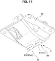
- a front-rear stopper mechanism 8M utilizing the front-rear lock unit 8 illustrated in FIGS. 16 to 18 is provided to suppress a swinging of the seat 5 in the front-rear direction relative to the support base part 2 at a predetermined position through an operation of an operating member 152 illustrated in FIG. 15 .
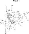
- a left-right stopper mechanism 7M utilizing the left-right lock unit 7 illustrated in FIGS. 19 and 20 is provided to suppress a swinging of the seat 5 in the left-right direction relative to the support base part 2 at a position determined in advance through an operation of an operating member 151 (being an operating member common with the operating member 152 in practice) illustrated in FIG. 15 .
- the left-right swing part 4 is supported by the support base part 2 and the front-rear swing part 3 is supported by the left-right swing part 4 so that a layered structure is formed in which the left-right stopper mechanism 7M is provided between the support base part 2 and the left-right swing part 4, and the front-rear stopper mechanism 8M is provided between the left-right swing part 4 and the front-rear swing part 3.
- the left-right stopper mechanism 7M is configured to switch between allowing and suppressing the swinging of the seat 5 in the left-right direction, by engaging or disengaging an engaging part 71 and an engaged part 72 illustrated in FIG. 21(a) when the operating member 151 illustrated in FIG. 15 is operated.
- the left-right stopper mechanism 7M includes an engagement pin 71a being the engaging part 71 provided at the side of the left-right swing part 4 and a groove 72a being the engaged part 72 provided on a sliding surface 20, the engaged part 72 relatively operating at the side of the support base part 2 being a position facing the engagement pin 71a.
- the engagement pin 71a is configured to be elastically biased toward the sliding surface 20, and to be fitted in the groove 72a at a predetermined position.
- the groove 72a has a rectangular shape in plan view and is provided at a center reference position in the left-right direction of the support base part 2 exposed upward via an opening 4t of the left-right swing part 4, and the engagement pin 71a illustrated in FIG. 20 is engaged to and disengaged from the groove 72a.
- a coil spring 73a being an elastic member 73 functions to bias the engagement pin 71a in a direction where the engagement pin 71a protrudes toward the sliding surface 20.
- the left-right stopper mechanism 7M includes a conversion mechanism 74 illustrated in FIGS.
- the casing 70 has a halved structure, and the engagement pin 71a is disposed to be liftable and lowerable in a state where a wide part 71aw of the engagement pin 71a is guided by inner surfaces of side walls 70a, 70b of the casing 70 while a tip end part 71as being a part of the engagement pin 71a protrudes from a lower end of the casing 70.
- the conversion mechanism 74 includes the above-described coil spring 73a provided elastically in a compressed state between an upper end of the engagement pin 71a and an upper wall 70p of the casing 70, a stopper operation arm 75 rotatably supported via a horizontal shaft 70c between the side walls 70a, 70b of the casing 70 at a position adjacent to the engagement pin 71a, a torsion coil spring 76 rotatably attached together with the stopper operation arm 75, and a wire tube 77 including a spherical wire tip end 77a to be attached to the stopper operation arm 75 and a tube tip end 77b locked to the casing 70. As illustrated in FIG.
- the other end of the wire tube 77 is locked in the vicinity of an operation lever 151a being the operating member 151 provided in the seat 5 and a wire base end 77c drawn therefrom is connected to the operation lever 151a.
- a tip end 76b of the torsion coil spring 76 is engaged with a hole 71a1 provided on the engagement pin 71a.
- an attachment part 70m provided in the casing 70 is mounted on an upper surface of the swing main body part 42 and fixed by screwing.
- the left and right side walls 70a, 70b of the casing 70 are tightly accommodated between left and right side walls 42a1, 42a2 of the unit attached hole 42a and the engagement pin 71a is tightly guided in the casing 70 by the inner surfaces of the side walls 70a, 70b of the casing 70.
- the unit attached hole 42a of a left-right swing part 13 illustrated in FIG. 7 includes merely the left and right side walls 42a1, 42a2, a rear wall 42a3, and an inclined front wall 42a4 to form the lower opening 4t without a bottom wall.
- the engagement pin 71a is configured to hang directly from the lower opening 4t of the unit attached hole 42a without being guided by the bottom wall to abut against the sliding surface 20, to engage with the groove 72a. Parts in the front-rear direction of the engagement pin 71a are supported by front and rear guide walls formed in the casing 70.
- the groove 72a is formed between longitudinal ribs r1, r1 provided in the support base part 2, lateral ribs r2 are provided around the longitudinal ribs r1, r1, and upper surfaces of the longitudinal ribs r1 and the lateral ribs r2 form the sliding surface 20 on which the engagement pin 71a slides until engaging with the groove 72a.
- the wire tube 77 rotates the stopper operation arm 75 to compress the coil spring 73a while the engagement pin 71a is lifted upwards at a tip end 76b of the torsion coil spring 76.
- the tip end 76b of the torsion coil spring 76 rotates together with the stopper operation arm 75 by the repulsive force of the coil spring 73a, the engagement pin 71a is pressed downward, and when the engagement pin 71a engages with the groove 72a of the support base part 2, the locked state in the left-right direction is realized.
- the front-rear stopper mechanism 8M is configured to switch between allowing and suppressing the swinging of the seat 5 in the front-rear direction, by engaging or disengaging an engaging element 81 and an engaged part 82 illustrated in FIG. 21(b) when the operating member 152 illustrated in FIG. 15 is operated.
- a configuration is so that the front-rear stopper mechanism 8M includes an engagement pin 81a being the engaging part 81 provided at the side of the front-rear swing part 3 and a groove 82a being the engaged part-82 provided on a sliding surface 40, the engaged part 82 relatively operating at the side of the left-right swing part 4 being a position facing the engagement pin 81a.
- the engagement pin 81a is configured to be elastically biased toward the sliding surface 40, and to fit in the groove 82a at a predetermined position.
- the groove 82a is provided on an upper surface of the swing main body part 42 of the left-right swing part 4 at one or more predetermined locations (one location in the present embodiment) within a movable range of the engagement pin 81a when the engagement pin 81a of the front-rear swing part 3 mounted on the upper surface of the swing main body part-42 moves in the front-rear direction, and thus, the groove 82a has a shape extending in the left-right direction and an upper surface of a swing main body part 41 forms the sliding surface 40.
- a coil spring 83a being an elastic member 83 functions to bias the engagement pin 81a in a direction where the engagement pin 81a protrudes toward the sliding surface 40, a conversion mechanism 84 illustrated in FIGS. 16 and 17 is provided, the conversion mechanism 84 converting an operation of the operating member 152 into an operation in a direction in which the engagement pin 81a is separated from the sliding surface 40, and the conversion mechanism 84, the engagement pin 81a, and the coil spring 83a are integrally incorporated into a half-piece of the casing 80 to form with unitized.
- the casing 80 has a flat saucer-shape opened upward, and thus, the engagement pin 81a is guided by a guide 80g1 in the casing 80, and is disposed to be liftable and lowerable with a part of the engagement pin 81a protruding from a lower end of the casing 80.
- the conversion mechanism 84 includes the above-described coil spring 83a provided elastically in a compressed state between an upper end of the engagement pin 81a and a cover 80a closing the upper opening of the casing 80, a stopper operation arm 85 rotatably supported by a horizontal shaft 80c disposed between side walls 80b, 80b of the casing 80 at a position adjacent to the engagement pin 81a, a torsion coil spring 86 rotatably attached together with the stopper operation arm 85, and a wire tube 87 having a spherical wire tip end 87a that is attached to the stopper operation arm 85 and a tube tip end 87b locked to the casing 80. As illustrated in FIG.
- the other end of the wire tube 87 is locked in the vicinity of an operation lever 152a being the operating member 152 provided in the seat 5 and a wire base end 87c drawn therefrom is connected to the operation lever 152a.
- a tip end 86a of the torsion coil spring 86 is at all times smoothly slidably engaged with a downward-facing surface 81a1 of the engagement pin 81a.
- a control mechanism 8X configured to automatically suppress a movement of the seat 5 in the front-rear direction at a predetermined position when the seated person leaves the seat, is provided along with the half-piece of an unit 8 of the front-rear stopper mechanism 8M.
- a configuration is such that a weight-receiving part 50 (see FIG. 15 ), the height position of which changes due to a person sitting on a seat surface, is provided substantially at a center position of the seat 5, the change of the height position is mechanically transmitted to the control mechanism 8X illustrated in FIGS. 16 and 18 configured to control an operation of the front-rear swing part 3 being the movable part, and the control mechanism 8X changes the operation of the front-rear swing part 3, that is, the front-rear operation of the seat 5, between allowed and suppressed states.
- the operation changer 8X changes the allowed/suppressed states of the operation of the front-rear swing part 3 when an engagement state of an engaging part 81X illustrated in FIG. 21(c) and provided in the front-rear swing part 3 being a movable part and an engaged part 82X provided in the left-right swing part 4 being a support part configured to support the front-rear swing part 3 changes due to the load applied by seated person, and returns, by the elastic member 83X, the state of the front-rear swing part 3 from an operation state where the operation of the front-rear swing part 3 is allowed to the original state where the operation of the front-rear swing part 3 is suppressed, when the load applied by seated person is removed.
- the chair is configured such that the engaged part 82X is a recess 82aX, and when the load applied by seated person is received in the state where the engaging part 81X is fitted into the recess 82aX, the fitted state is released, so that the engaging part 81X and the engaged part 82X are disengaged due to the load applied by seated person, and when the load applied by seated person is removed, the engaging part 81X and the engaged part 82X engage with each other by the elastic force to bring the front-rear swing part 3 into an operation-suppression state.
- the control mechanism 8X includes an engagement pin 81aX being the engaging part 81X; and a groove-shaped recess 82aX being an engaged part 82X provided on a sliding surface 40X relatively operating at a position facing the engaging pin 81X.
- the engagement pin 81aX is configured to be elastically biased toward the sliding surface 40X, and to fit in the groove-shaped recess 82aX at a predetermined position. Then, when the seat 5 detects received of the load applied by seated person in a central part, the control mechanism 8X illustrated in FIGS. 16 and 17 separates the engagement pin 81aX from the groove-shaped recess 82aX.
- a coil spring 83aX being an elastic member 83X functions to bias the engagement pin 81aX in a direction where the engagement pin 81aX protrudes toward the sliding surface 40X.
- the control mechanism 8X includes a conversion mechanism 84X configured to convert an operation of the weight-receiving part 50 due to a person sitting on the seat, into an operation in a direction where the engagement pin 81aX is separated from the sliding surface 40X, and the conversion mechanism 84X, the engagement pin 81aX, and the coil spring 83aX are integrally incorporated into an other-half part of the casing 80 illustrated in FIG. 16 , to form with unitized.
- the engagement pin 81aX is disposed to be 1 liftable and lowerable along front, rear, right, and left guides 80g2 of the casing 80, in a parallel relationship with the engagement pin 81 in the flat casing 80 configuring the front-rear stopper mechanism 8M.
- the conversion mechanism 84X includes the coil spring 83aX provided elastically in a compressed state between an upper end of the engagement pin 81aX and the cover 80a closing the upper opening of the casing 80, a safety operation arm 85X rotatably supported by the horizontal shaft 80c disposed between side walls 80b, 80b of the casing 80 at a position adjacent to the engagement pin 81aX, and a torsion coil spring 86X rotatably attached together with the safety operation arm 85X.
- the weight-receiving part 50 is, as illustrated in FIG.
- a pressure-receiving plate 52a rotatably fitted and attached to the seat outer shell 51 included in the seat 5, and a convex part 52b provided below the pressure-receiving plate 52a is disposed at a position displaced from the center of rotation of the safety operation arm 85X, where the convex part 52b can press a pressed part 85xt illustrated in FIG. 16 .
- a tip end 86aX of the torsion coil spring 86X is at all times smoothly slidably engaged with a downward-facing surface of the engagement pin 81aX.
- the pressure-receiving plate 52a is biased in a direction away from the safety operation arm 85X by a coil spring 52c being an elastic body illustrated in FIG. 26 .
- a hole part 53x configured to avoid interference with the pressure-receiving plate 52a is provided at a corresponding position of a seat inner shell 53.
- the control mechanism 8X when a user is seated, the control mechanism 8X is unlocked, and afterwards, whether or not the seated person locks a movement in the front-rear direction depends on the state of a front-rear fixing stopper mechanism 8M, via the operation of the operating member 152, and when the seated person leaves the seat, the state is maintained unless the front-rear fixing stopper mechanism 8M is unlocked, and if the front-rear fixing stopper mechanism 8M is unlocked, the control mechanism 8X actuates to lock the front-rear operation of the seat 5.
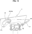
- the seat 5 tilts at least back and forth, and when the seated person starts standing up, the seat 5 moves while tilting forward together with the front-rear swing part 3, as illustrated in FIG. 13 .
- the engagement pin 81aX being the engaging part 81X illustrated in FIG. 21(c) settles on the sliding surface 40X in the front of the recess 82aX being the engaged part 82X.
- the seat 5 starts moving while tilting rearward in accordance with a relationship of the center-of-gravity position between the back and the seat, due to the presence of the back 6.
- the engagement pin 81aX being the engaging part 81X engages with the recess 82aX being the engaged part 82X.
- grooves are provided in a linked manner in an orthogonal direction, and a buffer material 82z such as rubber is embedded.
- the buffer material 82z is for avoiding collision of the engagement pin 81aX with the wall of the recess 82aX and a shock or an abnormal noise caused, and after colliding with the buffer material 82z.
- the engagement pin 81aX collides with the buffer material 82z and fits into the recess 82aX.
- the engagement pin 81aX and the recess 82aX are disengaged, however, the engagement pin 81aX and the recess 82aX engage with a certain degree of resistance, and thus, the locked state is not released immediately after the person sits on the seat, but is released when the resistance decreases due to a small movement of the seat 5.
- control mechanism 8X switches the locked state of the seat 5 between when the seated person leaves the seat and when sitting on the seat, and thus, may be called a “seat-leaving and seat-sitting automatic stopper mechanism".
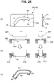
- a flange part 31b is provided on the plate member PM of the front-rear swing part 3 being the movable portion in which the guide hole 34 is provided, that is, on a vertical surface 31a of the rail plate 31, and a guide surface 31b1 for moving the bearing 45a being the rolling body 45 in the longitudinal direction is provided at a position extending in the lateral direction of the flange part 31b, that is, in the horizontal direction in the attached state.
- a lateral dimension w1 of the guide surface 31b1 is greater than a thickness t1 of the rail plate 31 being the plate member PM.
- the guide surface 31b1 is integrally formed of metal together with the rail plate 31. As illustrated in FIG. 3 and the like, the flange part 31b has a shape-that goes around the circumference of the guide hole 34 opened in the vertical surface.
- the flange part 31b is configured by plastic deformation processing of the plate member PM around the guide hole 34, and specifically, by adopting burring processing.
- burring processing a pilot hole is opened in a plate member, the periphery of the pilot hole is fixed with a jig and in this state, the edge of the pilot hole is raised, by pressing with a tool larger than the pilot hole, to form a flange part, and thus, a cylindrical flange is generally formed. So far, burring processing has only been utilized for forming tapped holes and the like and has not been considered for producing a structure for guiding a rolling body.
- a pilot hole 34x corresponding to the shape of the guide hole 34 is opened with a slightly smaller size than the guide hole 34, as illustrated in FIG. 28(b) .
- the periphery of the pilot hole 34x is fixed with a jig 34Z along the shape of the guide hole 34, and in this state, pressing is performed with a tool 34Y that is larger than the pilot hole 34x and corresponds to the inner circumferential shape of the guide hole 34.
- the flange part 31b extending in the lateral direction via a portion R from the vertical surface 31a is formed over the entire circumference of the guide hole 34, and the flange part 31b directed in this lateral direction is substantially the pressure-receiving area.
- the lateral dimension of the guide surface 31b1 is substantially uniform over the entire circumference.
- the manufacturing means for the guide hole 34 is selected based on the conditions that the guide surface 31b1 is smooth, the guide surface 31b1 has strength, and the manufacturing cost is low. Fine blanking processing and other processing were also tried, however, it turned out that, even though the fine blanking processing relatively likely to be selected was excellent in forming a smooth guide surface, the plate member needed to have a considerable thickness to obtain strength. Thus, the fine blanking processing could not be adopted due to its inappropriate cost and other processing also did not satisfy the conditions above. Overall, it turned out that burring processing met these conditions very suitably.
- the flange part 31b formed in this way extends outward from the pair of rail plates 31, 31, rather than inward in the left-right direction, and the guide surface 31b1 being a rolling surface is formed outside the rail plates 31.
- one end (the front end or the rear end) of the guide hole 34 is formed with a so-called shockless part in which the radius of curvature is changed, so that as the bearing 45a approaches the end due to an operation of the seat 5, the operation speed of the seat 5 is reduced by performing control so that the center of gravity of the seat 5 is lifted.
- the flange part 31b1 made by burring is designed to withstand the shock caused during this time.
- a lower region of the guide hole 34 causes the bearing 45a being the rolling body 45 to abut against the lower region of the guide hole 34 to support the bearing 45a and the flange part 31b contributes to supporting the load during this time.
- the flange part 31b includes an upper-side first flange area A1 supporting the back and forth movement of the bearing 45a being the rolling body 45 when the seat 5 operates back and forth, a front-side second flange area A2 supporting a portion where the bearing 45a being the rolling body 45 reaches the front end of the guide hole 34 when the seated person leans against the back 6, and a rear-side third flange area A3 supporting a portion where the bearing 45a being the rolling body 45 reaches the rear end of the guide hole 34 when the seated person leans forward.
- the flange part 31b includes a lower-side fourth flange area A4 supporting the bearing 45a being the rolling body 45 when the left-right support state is unbalanced. This structure remains similar, even if the guide hole 34 is formed at the side of the support portion and the bearing 45a being the rolling body 45 is disposed at the side of the movable portion.
- the guide hole 34 is formed in the vertical surface of the movable portion or the support portion of the chair and moves while receiving the load applied by seated person.
- the movable portion is supported at two locations on the front and rear side by the support portion including a guide structure configured by the rolling body 45 and the guide hole 34.
- the other movable portion of the chair is supported by the link arm LA, any one of the front and rear support structures is configured by the above-described rolling body 45 and the guide surface 31b1, and the other is configured by a different support structure, that is, in this embodiment, of the link structure.
- the back 6 is arranged behind the seat 5 and the backrest 62 is configured to be supported by the back frame 61 via the operating mechanism 6M.
- a back inner cover 63 is attached to the back frame 61, an opening 63a is provided in the back inner cover 63, and the backrest 62 is operatively supported by the back frame 61 via the opening 63a.
- the backrest 62 includes a cushion arranged on the front surface of a back plate 62a and the backrest 62 is entirely covered by an upholstery fabric.
- a lower end of the backrest 62 is disposed at a predetermined distance above the seat surface and the backrest 62 is supported on a back surface side by a back support part 61a at an upper end of the back frame 61 via the operating mechanism 6M.
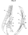
- the operating mechanism 6M includes: a base part 64 fixed to or formed integrally with the back plate 62a included in the backrest 62 and including an elastic member 65 arranged on a back surface side of the base part 64; a tilting part 65 disposed at a position adjacent to the base part 64 and including a guide part 65a recessed in a tapered shape at the back surface side, the center of the guide part 65a being open in the front-rear direction; and a pressing tool 66 including a guide part 66a having a convex shape corresponding to the guide part 65a of the tilting part on the front surface side of the pressing tool, the pressing tool 66 being fixed to the base part 64 via the opening of the tilting part 65 in a state where the guide part 66a of the pressing tool is fitted into the guide part 65a, as illustrated by an arrow J in FIG.
- a configuration of the operating mechanism 6M is such that the tilting part 65 is pulled and passed through the opening of the back inner cover 63 to be fixed by a screw to the back support part 61a at the upper end side of the back frame 61. That is, as illustrated in FIG. 31 , the pressing tool 66 is fixed to the base part with the tilting part 65 interposed therebetween, and thus, the pressing tool 66 is integrally formed with the base part 64 to form a part of the base part 64.
- the tilting part 65 can move freely in the gap between the base part 64 and the pressing tool 66, however, a configuration is such to allow for free movement of the tilting part 65, it is necessary to compress an elastic body 67 interposed between the tilting part 65 and the base part 64 against the elastic force.
- the elastic body 67 exerts a force on the guide part 65a of the tilting part 65 in a direction where the guide part 65a is constantly fitted in the guide part 66a of the pressing tool 66.
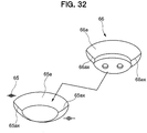
- the recess guide part 65a of the tilting part 65 has a substantially partially elliptical mortar-like shape including at least one valley line 65ax (two in this embodiment), the convex guide part 66a of the pressing tool 66 has a curved shape having at least one ridge line 66ax (two in this embodiment) fitted smoothly into the valley line 65ax, and the valley line 65ax and the ridge line 66ax can be fitted into each other.
- the convex guide part 66a is similar to a shape obtained by eliminating a part of an elliptical sphere, and the ridge line 66ax is formed along a line by a guide surface 66a intersected on the long axis side of the elliptical sphere. In a corresponding position of the matching recess guide part 65a, the valley line 65ax is also formed at the position where the guide surfaces 65a are intersected. The reason therefore is that a spherical body and a spherical surface-receiving seat do not have directionality and cannot perform a positioning function.
- the convex guide part 66a and the recess guide part 65a are not limited to the mortar-like shape and the shape of the elliptical sphere, as long as they have different shapes that uniquely determine the directionality during fitting.
- the guide elements 66a, 65a need to be configured of a smooth continuous surface.
- the ridge line 66ax and the valley line 65ax are provided to enhance the positioning function during fitting.
- urethane is used for the elastic body 67, and as illustrated in FIG. 29 , the elastic body 67 is arranged from the left and right corner parts to the upper edge portion of the upper half of the rectangular plate-shaped base part 64. As illustrated in FIG. 31 , the thickness dimension of the elastic body 67 is set to achieve an appropriately compressed state in a state where the pressing tool 66 is attached to the base part 64, the tilting part 65 is attached to the back support part 61a of the back frame 61, and the guide part 66a of the pressing tool 66 and the guide part 65a of the tilting element 65 are fitted into each other.
- the elastic body 67 is not provided in the lower half of the base part 64 where there is little occasion to perform a function substantially, however, provision of the elastic body 67 in this position shall not be precluded.
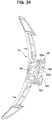
- FIG. 33 illustrates a rearward tilted state when a load is applied to the upper part of the back 6, and FIG. 34 is a plane cross section thereof. Further, FIG. 35 illustrates a turning operation of the back 6 in a case where the seated person twists its body and the like.
- the backrest 62 is disposed in a positional relationship where the backrest 62 moves against the elastic reaction force in the rearward direction and the turning direction while being supported by the elastic body 67, and a configuration is such that, when the elastic body 67 is deformed to the front, rear, right, or left in accordance with the amount of turning movement in the front, rear, right, or left directions, the reaction force returning the backrest 62 to a neutral position increases.
- the turning direction includes a turning movement in the left-right direction in front view, as illustrated in FIG. 35 , and further, in a clockwise or counterclockwise direction in front view.
- the guide part 65a of the tilting part 65 and the guide part 66a of the pressing tool 66 included in the base part 64 are guided to, and a shape of the guide parts 66a, 65a are in pressure contact with each other to be guided by the elastic body 67 and stands still to the reference position illustrated in FIG. 31 .
- the guide part 65a of the tilting part 65 and the guide part 66a of the pressing tool 66 included in the base part 64 are at least partly separated, as illustrated in FIGS. 33 , 34 , and 35 , so that the backrest 62 moves freely.
- the base part 64 and the tilting part 65 relatively move relative to the reference position in accordance with an amount of the received pressure and when the load is removed, the operating position is automatically returned, along the guide parts 66a, 65a, to the neutral position of FIG. 31 where the ridge line 66ax and the valley line 65ax coincide with each other.
- the backrest 62 is configured so that a gap SP between the guide parts 66a, 65a widens in accordance with a movement in the rear direction with respect to the back frame 61, and as a result, a turning range in the left-right direction expands and a return reaction force generated when the load is removed increases in accordance with the amount of turning movement in both the left and right directions.
- the base part 64 and the tilting part 65 are provided with engaging elements 64b, 65b configured to restrict a relative movement of the base part 64 and the tilting part 65 in collaboration with the guide parts 65a, 66a.
- the base part 64 includes an upright wall 64c at a peripheral edge, and a window 64b1 to be the engaging part 64b opens in a rectangular shape in the upright wall 64c.
- an L-shaped claw 65b1 to be the engaging part 65b is formed at a position displaced downward on the front side.
- the base part 64 and the tilting part 65 are assembled with the claw 65b1 loosely fitted in the window 64b1, and a movable range of the tilting part 65 with respect to the base element 64 is restricted to a range where the claw 65b1 can move in the window 64b1.
- a part of the backrest load is also supported in this restriction portion.
- the left-right turning operation of the back 6 occurs with respect to the back frame 61 and the seat 5 is attached to the front-rear swing part 3 to which the back frame 61 is attached, and thus, the back frame 61 and the seat 5 integrally swing in the left-right direction in front view, however, the backrest 62 further performs a different movement separately from the left-right turning operation of the seat 5 and the back frame 61.
- the base part 64 is attached to the backrest 62 and the tilting part 65 is attached to the side of the back frame 61, however, a configuration may be so that the base part 64 is attached to the side of the back frame 61 and the tilting part 65 is attached to the side of the backrest 62.
- the seat 5 is configured to be supported to be swingable to the front, rear, right, or left with respect to the support base part 2, however, a feeling of pressure on a femoral region of the left and right legs of the seated person sitting on the chair configured to swing to front, rear, right, or left, may change to be unbalanced depending on the posture of the seated person.
- the back 6 is provided to tilt rearward behind the seat 5 and when the back 6 tilts rearward, the seat 5 moves together with the back 6 and performs an operation in which the front part of the seat 5 rises relative to the back part of the seat 5 which descends, and as a result, the seated person may experience a feeling of pressure on the femoral region of the legs when leaning rearward and anxiety or instability due to the legs of the seated person being lifted in the air.
- this chair is provided with a deformation part 5X configured to change its shape in the up-down direction when receiving the load applied by seated person on a front part 5f of the seat 5.
- the deformation part 5X is provided at a position receiving the weight of the legs of the seated person, and is configured to deform downward when receiving the weight of the legs and to return upward when the weight of the legs is removed.
- a cushion material 54 covered by a non-illustrated upholstery fabric is arranged on the seat inner shell 53, and the seat outer shell 51 is attached below the seat inner shell 53.
- the seat inner shell 53 is configured by connecting a rear part 53a and a front part 53b with a resin hinge part 53c, and the front part 53b is elastically deformed with respect to the rear part 53a with the resin hinge part 53c as a boundary. Together with this deformation, the cushion material 54 is also deformed, and thus, these portions configure the deformation part 5x.
- the seat outer shell 51 is fixed to the front-rear swing part 3, and the rear part 53a of the seat inner shell 53 is attached above the seat outer shell 51.
- the deformation part 5x including the front part 53b of the seat inner shell 53 is deformed toward the seat outer shell 51.
- a front seat lower cover 55 is attached to the front part 53b forming the deformation part 5X of the seat inner shell 53, with the seat outer shell 51 interposed therebetween.
- FIG. 15 gives the impression that the front seat lower cover 55 is attached to the front part of the seat outer shell 51, the front seat lower cover 55 is actually arranged below the front part of the seat outer shell 51 in a non-connected state and is coupled to the deformation part 5X of the seat inner shell 53 above, as illustrated in FIGS. 39 and 40 . As illustrated in FIG.
- the left-right dimensions of the front seat lower cover 55 correspond substantially to the left-right dimensions of the front part 53b of the seat inner shell 53, and thus, a base end 55a of the front seat lower cover 55 is attached to an engaged part 53b1 (refer to FIGS. 39 and 40 ) set in the front part 53b of the seat inner shell 53, with the seat outer shell 51 interposed therebetween and a rear end 55b of the front seat lower cover 55 is shaped to extend rearward and downward along the seat outer shell 51.
- compression springs 56 being elastic bodies are arranged at positions compressed between the front part 53b of the seat inner shell 53 and the front part of the seat outer shell 51.
- a resin hinge 53c is shaped as a corrugated plate having a series of uneven portions, and the deformation part 5X has a structure that easily causes, in accordance with an unbalanced load received in a left-side region and a right-side region of the seat 5, regardless of the up-down direction, torsional deformation so that one side of the seat 5 in the left-right direction is lifted higher than the other side.
- a fixed attachment part 91 extending upward is attached to an arm attachment part 23 of the support base part 2 to bypass the seat 5 and even if the seat 5 swings to the front, rear, right, or left, the fixed attachment part 91 remains in a fixed position that does not interfere with the seat 5.
- a movable cover mechanism 92 in which a plurality of covers are combined is disposed below the seat 5 to not interfere with the relative operation of the front-rear swing part 3 and the left-right swing part 4 and to hide the front-rear swing part 3 and the left-right swing part 4.
- the chair according to the present embodiment is configured such that the back 6 is arranged behind the seat 5, and the back 6 has an operation mechanism 6M turning-movable supporting the load received from a seated person in left-right direction in a front view, and when the load is applied, at least a part of guide parts 65a, 66a of the operation mechanism 6M is separated, and the back 6 moves freely, and when the applied load is removed, the back 6 automatically returns to the neutral position along the guide parts 65a, 66a.
- the back 6 is turning-movable in a front view in a left-right direction, and when the load is applied, at least a part of guide parts 65a, 66a of the operation mechanism 6M is separated, and the back 6 moves freely. Therefore, it can be easily adapted to various movement of the seated person. Further, when the seated person leaves a seat, the back 6 reliably returns to the neutral position along guide parts 65a, 66a. Therefore, even if the degree of freedom of back 6 movement is increased, a plurality of chairs is easily uniform in appearance when the seated person leaves a seat. Further, it is possible to avoid the situation in that the initial condition of the chair differs every time the seated person sits on the seat.
- the chair is configured such that a reaction force with which the back 6 returns to the neutral position becomes larger in accordance with an amount of turning movement to both of the left and right directions. Therefore, the load in turning direction is easily balanced and an appropriate reaction force in accordance with the seated person's posture is easily obtained.
- the back 6 is configured such that a backrest 62 is supported by a back frame 61 via the operation mechanism 6M, the back frame 61 is erected at the rear of the seat 5, and the backrest 62 is turning movably attached to the back frame 61 substantially clockwise or counterclockwise direction in a front view via the operation mechanism 6M. Therefore, the operation mechanism 6M is configured only by introducing a simple turning mechanism or loose convex-concave structure in a part of the backrest 62.
- the back 6 is configured such that the backrest 62 is supported by the back frame 61 via the operation mechanism 6M, and the backrest 62 moves via the operation mechanism 6M having an elastic body 67 toward the rear direction and the turning direction against an elastic reaction force. Therefore, supporting force and returning force in accordance with size of displacement can be provided by moving the backrest 62 against the elastic reaction force of the elastic body 67.
- the backrest 62 is configured such that a turning range to left-right direction becomes larger in accordance with the movement in the rear direction with respect to the back frame 61, and the turning operation of the seated person to left-right direction becomes larger as the seated person deeply leans against the backrest 62. Therefore, it is possible to realize the support that matches body movement of the seated person.
- the seat 5 is swingable in the left-right direction in a front view, and the back 6 performs a left-right turning operation separated from the seat 5. Therefore, left-right swinging of the seat 5 and left-right turning operation of the backrest 62 work together through the seated person's posture. In consequence, it is possible to realize an appropriate support state in accordance with the seated person's posture.
- the operation mechanism 6M is provided with a base part 64 and a tilting part 65, and includes a reference position, a guide part 66a set at the side of the base part 64 and a guide part 65a set at the side of the tilting part 65 are in pressure contact with each other to be guided by the shapes of the guide parts 66a, 65a and stopped at the reference position, and when the pressure contact is loosened by the received pressure from the seated person, the base part 64 and the tilting part 65 can be relatively changed from the reference position in accordance with the degree of the received pressure. Therefore, while the operation mechanism 6M has a simple structure, the operation mechanism 6M has a function to return to the reference position when the applied load is removed, and can be incorporated as an operation unit for various intended use including the present embodiment.
- the chair is configured such that the pressure contact of the both guide parts 66a, 65a is formed by the elastic body 67 and the elastic body 67 is pressed by the received pressure, whereby the guide part 65a of the tilting part 65 and the guide part 66a of the base part 64 are separated. Therefore, the elastic body 67 can serve as a role to flexibly receive the load of the backrest and as a role to return the guide parts, 66a, 65a to the reference position.
- the operation mechanism 6M includes: the base part 64 fixed to the backrest 62 and provided with the elastic body 67 on the back surface side of the base part 64; the tilting part 65 disposed at a position adjacent to the base part 64 and including a guide part 65a recessed in a tapered shape at the back surface side of the tilting part, the bottom part of the guide part 65a having an opening; and a pressing tool 66 including a guide part 66a having a convex shape corresponding to the guide part 65a of the tilting part on the front surface side of the pressing tool, the pressing tool 66 being fixed to the base part 64 via the opening of the tilting part 65 in a state where the guide part 66a of the pressing tool is fitted into the guide part 65a of the tilting part, and the tilting part 65 is fixed to the back support part 61a provided at the upper end part of the back frame 61. Accordingly, a structure that allows an easy assembly can be realized.
- one guide part 65a has a substantially partially elliptical mortar-like shape including at least one valley line 65ax and the other guide part 66a has a curved shape having at least one ridge line 66ax fitted smoothly into the valley line 65ax, and the valley line 65ax and the ridge line 66ax can be fitted into each other.
- the positioning function at the reference position can be enhanced.
- the base part 64 and the tilting part 65 are provided with engaging parts 64b,65b configured to regulate a relative movement of the base part 64 and the tilting part 65 in collaboration with the guide parts 66a,65a, and a part of the load of the backrest is supported by these engaging parts, 64b, 65b. Therefore, it is possible to prevent the local load from concentrating on the guide parts, 6a, 65a.
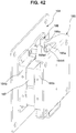
- the chair illustrated in FIG.41 , 42 and 43 includes an operation mechanism 106M different from one of the above-described embodiments at the back to support turning-movably the load received from seated person in left-right direction in front view.
- the operation mechanism 106M is also configured such that when the load is applied, at least a part of guide parts, 165a, 166a of the operation mechanism is separated and the back moves freely, and when the applied load is removed, the operating position of the operation mechanism 160M automatically returns to the neutral position along the guide parts, 165a, 166a of the operation mechanism 106M.
- the operation mechanism 106M is provided with a base part 164 and a tilting part 165, and includes a reference position, a guide part 166a set at the side of the base part 164 and a guide part 165a set at the side of the tilting part 165 are in pressure contact with each other to be guided by the shapes of the guide parts 166a, 165a, and stopped at the reference position, and when the pressure contact is loosened by the received pressure from the seated person, the base part 164 and tilting part 165 can be relatively changed from the reference position in accordance with the degree of the received pressure.
- This function is also the same as one of the above-described embodiment.
- One guide part 166a is a shaft-shaped part 166 extended upward and downward, or leftward and rightward and the other guide part 165a is a V-groove leading the upper-lower or left-right shaft-shaped member 166 to the center position.
- a semicircle groove bottom 165a1 that defines the reference position at the center of the groove is formed.
- the tilting part 165 is freely movable in a gap between the base part 164 and the shaft shaped member 166. For the free movement, it is configured so as to be required to press an elastic body 167 interposed between the tilting part 265 and the base part 164 against the elastic force.
- the shaft-shaped member 166 is dividedly placed at the position avoiding the elastic body 167, and kept in the position by supporting members, 164b, 165b. With the configuration, the operation mechanism is simply realized.
- the V-groove is formed in a part of a window 164b1 being an engaging part and a part of the shaft-shaped part 166 being an engaging part is relatively-movable in the range controlled by the window 164b1. Therefore, it can be said that the base part 164 and the tilting part 165 are provided with the engaging parts configured to regulate the relative movement of the base part 164 and the tilting part 165 in collaboration with the guide parts, 165a, 166a. As a part of the load of the backrest is supported by the engaging part, it is possible to prevent the local load from concentrating on the guide part.
- the chair illustrated in FIG.44 , 45 and 46 is also configured such that the back 6 is arranged behind the seat, and the back has an operation mechanism 206M turning-movably supporting the load received from a seated person in a left-right direction in a front view, and when the load is applied, at least a part of guide parts 265a1, 266a1 (265a2, 266a2) of the operation mechanism is separated and the back moves freely, and when the applied load is removed, the operating position of the operation mechanism 206M automatically returns to the neutral position along the guide parts 265a1, 266a1 (265a2, 266a2) of the operation mechanism 206M.
- the seat is swingable in the left-right direction in a front view, and the back 6 performs a left-right turning operation separated from the seat.
- the operation mechanism 206M is provided with a base part 264, a tilting part 265, and a back frame received pressure part 261a at the upper end side of a back frame 261, and. includes a reference position, a first guide part 266a1 set at the side of the base part 264 and a first guide part 265a1 set at the side of the tilting part 265 are in pressure contact with each other, and pressure contact of a second guide part 266a2 set at the side of the base part 264 and a second guide part 265a2 set at the side of the back frame received pressure part 261a are in pressure contact with each other to be guided by the shapes of the guide parts 266a1, 265a1(266a1, 265a1) and stopped at the reference position, when the pressure contact is loosened by the received pressure from the seated person, the base part 264 is integrated with the pressing tool 266 in accordance with the degree of the received pressure and can be relatively changed from the reference position with respect to the tilting part 265 and the back
- the operation mechanism 206M includes: the base part 264 fixed to or formed integrally with the back plate included in the backrest, and provided with the pressing tool 266 at the side of the back surface in an a protruding condition; the tilting part 265 disposed at a position adjacent to the base part 264, including the first guide part 265a1 recessed in a tapered shape at the back surface side of the tilting part, the center of the tilting part 265 having an opening in front-rear direction; and the back frame received pressure part 261a placed at the position facing the tilting part 265 interposing the pressing tool 266 and having the second guide part 265a2 that is recessed in a tapered shape on the front surface side.
- the pressing tool 266 is provided with the first convex guide part 266a1 and the second convex guide part 266a2 corresponding to the first guide part 265a1 and the second guide part 265a2 on the front surface side or the back surface side.
- the pressing tool 266 is fixed to the base part 264 through the opening of the tilting part 265, and the tilting part 265 is drawn and fixed by a screw to the back support part 261a at the upper end side of the back frame 261 configuring the back 206 as shown by arrow K1.
- the first elastic body 267a1 is interposed between the pressing tool 266 and the back frame received pressure part 261a
- the second elastic body 267a2 is interposed between the pressing tool 266 and the tilting part 265.
- the pressing tool 266 is fixed to the base part 264 in a state where the tilting part 265 is interposed between the pressing tool 266 and the base part 264, whereby, the pressing tool 266 is integrated with the base part 264 and configures a part of the base part 264.
- the pressing tool 266 is freely movable in a gap between the base part 264 and the back frame received part 261a. To freely move, the pressing tool 266 is configured such that it is required to compress the elastic body 267 interposed among the tilting part 265, the back frame received pressure part 261a and the pressing tool 266 against the elastic force.
- the force in the direction where the guide part 266a1 of the pressing tool 266 is constantly fitted into by the elastic body 267a1, is applied to the guide part 265a1 of the tilting part 265, and the force in the direction where the guide part 266a2 of the pressing tool 266 is constantly fitted into by the elastic body 267a2, is applied to the guide part 265a2 of the back frame received pressure part 261a.
- the first guide part 266a1 and the second guide part 266a2 of the pressing tool 266 are provided with three protruding parts resembling propeller blade, and the first guide part 265a1 at the side of the tilting part 265 and the second guide part 265a2 at the side of the back frame received pressure part 261a that receives- the protruding parts have a notch groove shape that receives a part of the three protruding parts.
- the guide parts 266a1, 266a2 have a polygonal line part being a convex and the guide parts 265a1, 265a2 are in a notch shape having a valley line part.
- the first guide part 266a1 at the side of the base part 264 is separated from the first guide part 265a1 at the tilting side and the second guide part 266a2 at the side of the base part 264 is separated from the second guide part 265a2 at the side of the back frame received pressure part 261a while the pressing tool 266 at the side of the base part 264 presses the first, second elastic members 267a1, 267a2.
- the base part 264 as well as the pressing part 266 can freely move, when the applied load is removed, the first elastic member 267a1, the second elastic member 267a2 press the pressing tool 266 to the tilting part 265 and the back frame received pressure part 261a, and the first guide part 266a1 engages with the second guide part 265a1 and second guide part 266a2 engages with the second guide part 265a2. Therefore, the back returns to the reference position.
- an object illustrated as the reference sign 265x in the drawing is a protrusion for dividing and storing the elastic part 267.
- the protrusion 264z and the opening 265z illustrated in the drawings make up an engaging part that regulates the range of free movement of the base part 264.
- the chair according to the present invention is configured as described above, the chair can be utilized especially suitably in an office and the like.
Landscapes
- Chairs For Special Purposes, Such As Reclining Chairs (AREA)
- Chairs Characterized By Structure (AREA)
- Chair Legs, Seat Parts, And Backrests (AREA)
Applications Claiming Priority (1)
| Application Number | Priority Date | Filing Date | Title |
|---|---|---|---|
| PCT/JP2017/022760 WO2018235175A1 (fr) | 2017-06-20 | 2017-06-20 | Chaise |
Publications (3)
| Publication Number | Publication Date |
|---|---|
| EP3643205A1 true EP3643205A1 (fr) | 2020-04-29 |
| EP3643205A4 EP3643205A4 (fr) | 2020-10-21 |
| EP3643205B1 EP3643205B1 (fr) | 2024-07-03 |
Family
ID=64736927
Family Applications (1)
| Application Number | Title | Priority Date | Filing Date |
|---|---|---|---|
| EP17914176.7A Active EP3643205B1 (fr) | 2017-06-20 | 2017-06-20 | Chaise |
Country Status (5)
| Country | Link |
|---|---|
| US (1) | US11103069B2 (fr) |
| EP (1) | EP3643205B1 (fr) |
| JP (1) | JP6896854B2 (fr) |
| CN (1) | CN110650657B (fr) |
| WO (1) | WO2018235175A1 (fr) |
Cited By (1)
| Publication number | Priority date | Publication date | Assignee | Title |
|---|---|---|---|---|
| EP3868256A4 (fr) * | 2018-10-19 | 2022-05-25 | Kokuyo Co., Ltd. | Chaise |
Families Citing this family (8)
| Publication number | Priority date | Publication date | Assignee | Title |
|---|---|---|---|---|
| US10881208B2 (en) * | 2016-02-23 | 2021-01-05 | Kokuyo Co., Ltd. | Chair and seat support mechanism |
| JP6735826B2 (ja) * | 2016-06-20 | 2020-08-05 | コクヨ株式会社 | 椅子及び座の支持機構 |
| EP3560386B1 (fr) * | 2016-12-21 | 2023-03-22 | Kokuyo Co., Ltd. | Chaise |
| JP6900478B2 (ja) * | 2017-06-20 | 2021-07-07 | コクヨ株式会社 | 椅子 |
| US11825949B2 (en) * | 2021-05-04 | 2023-11-28 | Michael David Collier | Ergonomic motion chair |
| US11229291B1 (en) * | 2021-05-04 | 2022-01-25 | Michael David Collier | Ergonomic motion chair |
| US12582232B2 (en) | 2021-05-04 | 2026-03-24 | Moovlab Inc. | Ergonomic motion chair |
| JP7484829B2 (ja) * | 2021-06-29 | 2024-05-16 | トヨタ自動車株式会社 | 椅子 |
Family Cites Families (17)
| Publication number | Priority date | Publication date | Assignee | Title |
|---|---|---|---|---|
| JPS46533Y1 (fr) * | 1967-09-18 | 1971-01-09 | ||
| JPS5135312A (en) | 1974-09-20 | 1976-03-25 | Toray Industries | Jikienban no seizoho |
| JP3135597B2 (ja) | 1991-04-19 | 2001-02-19 | 株式会社日立製作所 | 表示制御装置の同期制御回路 |
| JP3555175B2 (ja) | 1994-05-27 | 2004-08-18 | アラコ株式会社 | 車両用シート |
| DE10048779A1 (de) * | 2000-09-29 | 2002-04-18 | Stoll Sedus Ag | Rückenlehne |
| GB0114581D0 (en) | 2001-06-14 | 2001-08-08 | White Adam | Twister seat |
| JP4735966B2 (ja) * | 2005-11-11 | 2011-07-27 | コクヨ株式会社 | 背支持装置、座支持装置及び椅子 |
| DE102006049677B4 (de) | 2006-10-18 | 2009-04-02 | Sedus Stoll Ag | Rückenlehne für einen Stuhl |
| JP3135597U (ja) | 2007-07-11 | 2007-09-20 | 舜 黄 | 椅子の背もたれ取り付け部材 |
| JP2009131357A (ja) * | 2007-11-29 | 2009-06-18 | Okamura Corp | 椅子 |
| JP5358821B2 (ja) * | 2008-01-16 | 2013-12-04 | コクヨ株式会社 | 椅子 |
| JP5514509B2 (ja) * | 2009-10-26 | 2014-06-04 | 株式会社イトーキ | ロッキング椅子 |
| EP2387913B1 (fr) | 2010-05-21 | 2013-03-27 | Karl-Heinz Brändle | Dispositif destiné à l'amélioration du maintien en position assise de l'humain |
| US10226127B2 (en) | 2010-11-25 | 2019-03-12 | Corechair Incorporated | Resistive support mechanism for a chair including user feedback |
| JP5863352B2 (ja) * | 2011-09-16 | 2016-02-16 | 株式会社イトーキ | 椅子 |
| CN105531147B (zh) | 2013-07-24 | 2017-11-03 | 丰田自动车株式会社 | 座椅 |
| DE102014103780B3 (de) | 2014-03-19 | 2015-06-18 | Wilkhahn Wilkening + Hahne Gmbh + Co. | Stuhl |
-
2017
- 2017-06-20 EP EP17914176.7A patent/EP3643205B1/fr active Active
- 2017-06-20 WO PCT/JP2017/022760 patent/WO2018235175A1/fr not_active Ceased
- 2017-06-20 US US16/614,571 patent/US11103069B2/en active Active
- 2017-06-20 CN CN201780090957.1A patent/CN110650657B/zh active Active
- 2017-06-20 JP JP2019524758A patent/JP6896854B2/ja active Active
Cited By (2)
| Publication number | Priority date | Publication date | Assignee | Title |
|---|---|---|---|---|
| EP3868256A4 (fr) * | 2018-10-19 | 2022-05-25 | Kokuyo Co., Ltd. | Chaise |
| US11533998B2 (en) | 2018-10-19 | 2022-12-27 | Kokuyo Co., Ltd. | Chair |
Also Published As
| Publication number | Publication date |
|---|---|
| EP3643205B1 (fr) | 2024-07-03 |
| JP6896854B2 (ja) | 2021-06-30 |
| CN110650657B (zh) | 2023-06-27 |
| WO2018235175A1 (fr) | 2018-12-27 |
| JPWO2018235175A1 (ja) | 2020-04-23 |
| US11103069B2 (en) | 2021-08-31 |
| US20200085195A1 (en) | 2020-03-19 |
| EP3643205A4 (fr) | 2020-10-21 |
| CN110650657A (zh) | 2020-01-03 |
Similar Documents
| Publication | Publication Date | Title |
|---|---|---|
| EP3643205B1 (fr) | Chaise | |
| EP3643203B1 (fr) | Chaise | |
| EP3643206B1 (fr) | Siège | |
| KR20130111950A (ko) | 의자 | |
| CN102089185A (zh) | 座椅靠背装置 | |
| US12108882B2 (en) | Chair having a movable seat | |
| EP3643204B1 (fr) | Chaise | |
| EP4159089B1 (fr) | Chaise | |
| JP6952509B2 (ja) | 椅子 | |
| JP2008080089A (ja) | 椅子 |
Legal Events
| Date | Code | Title | Description |
|---|---|---|---|
| STAA | Information on the status of an ep patent application or granted ep patent |
Free format text: STATUS: THE INTERNATIONAL PUBLICATION HAS BEEN MADE |
|
| PUAI | Public reference made under article 153(3) epc to a published international application that has entered the european phase |
Free format text: ORIGINAL CODE: 0009012 |
|
| STAA | Information on the status of an ep patent application or granted ep patent |
Free format text: STATUS: REQUEST FOR EXAMINATION WAS MADE |
|
| 17P | Request for examination filed |
Effective date: 20191119 |
|
| AK | Designated contracting states |
Kind code of ref document: A1 Designated state(s): AL AT BE BG CH CY CZ DE DK EE ES FI FR GB GR HR HU IE IS IT LI LT LU LV MC MK MT NL NO PL PT RO RS SE SI SK SM TR |
|
| AX | Request for extension of the european patent |
Extension state: BA ME |
|
| DAV | Request for validation of the european patent (deleted) | ||
| DAX | Request for extension of the european patent (deleted) | ||
| A4 | Supplementary search report drawn up and despatched |
Effective date: 20200922 |
|
| RIC1 | Information provided on ipc code assigned before grant |
Ipc: A47C 3/026 20060101ALI20200916BHEP Ipc: A47C 7/48 20060101AFI20200916BHEP |
|
| P01 | Opt-out of the competence of the unified patent court (upc) registered |
Effective date: 20230426 |
|
| STAA | Information on the status of an ep patent application or granted ep patent |
Free format text: STATUS: EXAMINATION IS IN PROGRESS |
|
| 17Q | First examination report despatched |
Effective date: 20230616 |
|
| GRAP | Despatch of communication of intention to grant a patent |
Free format text: ORIGINAL CODE: EPIDOSNIGR1 |
|
| STAA | Information on the status of an ep patent application or granted ep patent |
Free format text: STATUS: GRANT OF PATENT IS INTENDED |
|
| INTG | Intention to grant announced |
Effective date: 20240228 |
|
| GRAS | Grant fee paid |
Free format text: ORIGINAL CODE: EPIDOSNIGR3 |
|
| GRAA | (expected) grant |
Free format text: ORIGINAL CODE: 0009210 |
|
| STAA | Information on the status of an ep patent application or granted ep patent |
Free format text: STATUS: THE PATENT HAS BEEN GRANTED |
|
| AK | Designated contracting states |
Kind code of ref document: B1 Designated state(s): AL AT BE BG CH CY CZ DE DK EE ES FI FR GB GR HR HU IE IS IT LI LT LU LV MC MK MT NL NO PL PT RO RS SE SI SK SM TR |
|
| REG | Reference to a national code |
Ref country code: CH Ref legal event code: EP |
|
| REG | Reference to a national code |
Ref country code: DE Ref legal event code: R096 Ref document number: 602017083105 Country of ref document: DE |
|
| REG | Reference to a national code |
Ref country code: LT Ref legal event code: MG9D |
|
| REG | Reference to a national code |
Ref country code: NL Ref legal event code: MP Effective date: 20240703 |
|
| PG25 | Lapsed in a contracting state [announced via postgrant information from national office to epo] |
Ref country code: PT Free format text: LAPSE BECAUSE OF FAILURE TO SUBMIT A TRANSLATION OF THE DESCRIPTION OR TO PAY THE FEE WITHIN THE PRESCRIBED TIME-LIMIT Effective date: 20241104 |
|
| REG | Reference to a national code |
Ref country code: AT Ref legal event code: MK05 Ref document number: 1698889 Country of ref document: AT Kind code of ref document: T Effective date: 20240703 |
|
| PG25 | Lapsed in a contracting state [announced via postgrant information from national office to epo] |
Ref country code: NL Free format text: LAPSE BECAUSE OF FAILURE TO SUBMIT A TRANSLATION OF THE DESCRIPTION OR TO PAY THE FEE WITHIN THE PRESCRIBED TIME-LIMIT Effective date: 20240703 |
|
| PG25 | Lapsed in a contracting state [announced via postgrant information from national office to epo] |
Ref country code: PT Free format text: LAPSE BECAUSE OF FAILURE TO SUBMIT A TRANSLATION OF THE DESCRIPTION OR TO PAY THE FEE WITHIN THE PRESCRIBED TIME-LIMIT Effective date: 20241104 Ref country code: NL Free format text: LAPSE BECAUSE OF FAILURE TO SUBMIT A TRANSLATION OF THE DESCRIPTION OR TO PAY THE FEE WITHIN THE PRESCRIBED TIME-LIMIT Effective date: 20240703 |
|
| PG25 | Lapsed in a contracting state [announced via postgrant information from national office to epo] |
Ref country code: NO Free format text: LAPSE BECAUSE OF FAILURE TO SUBMIT A TRANSLATION OF THE DESCRIPTION OR TO PAY THE FEE WITHIN THE PRESCRIBED TIME-LIMIT Effective date: 20241003 |
|
| PG25 | Lapsed in a contracting state [announced via postgrant information from national office to epo] |
Ref country code: GR Free format text: LAPSE BECAUSE OF FAILURE TO SUBMIT A TRANSLATION OF THE DESCRIPTION OR TO PAY THE FEE WITHIN THE PRESCRIBED TIME-LIMIT Effective date: 20241004 Ref country code: FI Free format text: LAPSE BECAUSE OF FAILURE TO SUBMIT A TRANSLATION OF THE DESCRIPTION OR TO PAY THE FEE WITHIN THE PRESCRIBED TIME-LIMIT Effective date: 20240703 Ref country code: PL Free format text: LAPSE BECAUSE OF FAILURE TO SUBMIT A TRANSLATION OF THE DESCRIPTION OR TO PAY THE FEE WITHIN THE PRESCRIBED TIME-LIMIT Effective date: 20240703 |
|
| PG25 | Lapsed in a contracting state [announced via postgrant information from national office to epo] |
Ref country code: BG Free format text: LAPSE BECAUSE OF FAILURE TO SUBMIT A TRANSLATION OF THE DESCRIPTION OR TO PAY THE FEE WITHIN THE PRESCRIBED TIME-LIMIT Effective date: 20240703 |
|
| PG25 | Lapsed in a contracting state [announced via postgrant information from national office to epo] |
Ref country code: LV Free format text: LAPSE BECAUSE OF FAILURE TO SUBMIT A TRANSLATION OF THE DESCRIPTION OR TO PAY THE FEE WITHIN THE PRESCRIBED TIME-LIMIT Effective date: 20240703 |
|
| PG25 | Lapsed in a contracting state [announced via postgrant information from national office to epo] |
Ref country code: AT Free format text: LAPSE BECAUSE OF FAILURE TO SUBMIT A TRANSLATION OF THE DESCRIPTION OR TO PAY THE FEE WITHIN THE PRESCRIBED TIME-LIMIT Effective date: 20240703 Ref country code: IS Free format text: LAPSE BECAUSE OF FAILURE TO SUBMIT A TRANSLATION OF THE DESCRIPTION OR TO PAY THE FEE WITHIN THE PRESCRIBED TIME-LIMIT Effective date: 20241103 |
|
| PG25 | Lapsed in a contracting state [announced via postgrant information from national office to epo] |
Ref country code: HR Free format text: LAPSE BECAUSE OF FAILURE TO SUBMIT A TRANSLATION OF THE DESCRIPTION OR TO PAY THE FEE WITHIN THE PRESCRIBED TIME-LIMIT Effective date: 20240703 Ref country code: CZ Free format text: LAPSE BECAUSE OF FAILURE TO SUBMIT A TRANSLATION OF THE DESCRIPTION OR TO PAY THE FEE WITHIN THE PRESCRIBED TIME-LIMIT Effective date: 20240703 |
|
| PG25 | Lapsed in a contracting state [announced via postgrant information from national office to epo] |
Ref country code: RS Free format text: LAPSE BECAUSE OF FAILURE TO SUBMIT A TRANSLATION OF THE DESCRIPTION OR TO PAY THE FEE WITHIN THE PRESCRIBED TIME-LIMIT Effective date: 20241003 Ref country code: ES Free format text: LAPSE BECAUSE OF FAILURE TO SUBMIT A TRANSLATION OF THE DESCRIPTION OR TO PAY THE FEE WITHIN THE PRESCRIBED TIME-LIMIT Effective date: 20240703 |
|
| PG25 | Lapsed in a contracting state [announced via postgrant information from national office to epo] |
Ref country code: RS Free format text: LAPSE BECAUSE OF FAILURE TO SUBMIT A TRANSLATION OF THE DESCRIPTION OR TO PAY THE FEE WITHIN THE PRESCRIBED TIME-LIMIT Effective date: 20241003 Ref country code: PL Free format text: LAPSE BECAUSE OF FAILURE TO SUBMIT A TRANSLATION OF THE DESCRIPTION OR TO PAY THE FEE WITHIN THE PRESCRIBED TIME-LIMIT Effective date: 20240703 Ref country code: NO Free format text: LAPSE BECAUSE OF FAILURE TO SUBMIT A TRANSLATION OF THE DESCRIPTION OR TO PAY THE FEE WITHIN THE PRESCRIBED TIME-LIMIT Effective date: 20241003 Ref country code: LV Free format text: LAPSE BECAUSE OF FAILURE TO SUBMIT A TRANSLATION OF THE DESCRIPTION OR TO PAY THE FEE WITHIN THE PRESCRIBED TIME-LIMIT Effective date: 20240703 Ref country code: IS Free format text: LAPSE BECAUSE OF FAILURE TO SUBMIT A TRANSLATION OF THE DESCRIPTION OR TO PAY THE FEE WITHIN THE PRESCRIBED TIME-LIMIT Effective date: 20241103 Ref country code: HR Free format text: LAPSE BECAUSE OF FAILURE TO SUBMIT A TRANSLATION OF THE DESCRIPTION OR TO PAY THE FEE WITHIN THE PRESCRIBED TIME-LIMIT Effective date: 20240703 Ref country code: GR Free format text: LAPSE BECAUSE OF FAILURE TO SUBMIT A TRANSLATION OF THE DESCRIPTION OR TO PAY THE FEE WITHIN THE PRESCRIBED TIME-LIMIT Effective date: 20241004 Ref country code: FI Free format text: LAPSE BECAUSE OF FAILURE TO SUBMIT A TRANSLATION OF THE DESCRIPTION OR TO PAY THE FEE WITHIN THE PRESCRIBED TIME-LIMIT Effective date: 20240703 Ref country code: ES Free format text: LAPSE BECAUSE OF FAILURE TO SUBMIT A TRANSLATION OF THE DESCRIPTION OR TO PAY THE FEE WITHIN THE PRESCRIBED TIME-LIMIT Effective date: 20240703 Ref country code: CZ Free format text: LAPSE BECAUSE OF FAILURE TO SUBMIT A TRANSLATION OF THE DESCRIPTION OR TO PAY THE FEE WITHIN THE PRESCRIBED TIME-LIMIT Effective date: 20240703 Ref country code: BG Free format text: LAPSE BECAUSE OF FAILURE TO SUBMIT A TRANSLATION OF THE DESCRIPTION OR TO PAY THE FEE WITHIN THE PRESCRIBED TIME-LIMIT Effective date: 20240703 Ref country code: AT Free format text: LAPSE BECAUSE OF FAILURE TO SUBMIT A TRANSLATION OF THE DESCRIPTION OR TO PAY THE FEE WITHIN THE PRESCRIBED TIME-LIMIT Effective date: 20240703 |
|
| REG | Reference to a national code |
Ref country code: DE Ref legal event code: R097 Ref document number: 602017083105 Country of ref document: DE |
|
| PG25 | Lapsed in a contracting state [announced via postgrant information from national office to epo] |
Ref country code: DK Free format text: LAPSE BECAUSE OF FAILURE TO SUBMIT A TRANSLATION OF THE DESCRIPTION OR TO PAY THE FEE WITHIN THE PRESCRIBED TIME-LIMIT Effective date: 20240703 Ref country code: RO Free format text: LAPSE BECAUSE OF FAILURE TO SUBMIT A TRANSLATION OF THE DESCRIPTION OR TO PAY THE FEE WITHIN THE PRESCRIBED TIME-LIMIT Effective date: 20240703 Ref country code: SM Free format text: LAPSE BECAUSE OF FAILURE TO SUBMIT A TRANSLATION OF THE DESCRIPTION OR TO PAY THE FEE WITHIN THE PRESCRIBED TIME-LIMIT Effective date: 20240703 |
|
| PG25 | Lapsed in a contracting state [announced via postgrant information from national office to epo] |
Ref country code: EE Free format text: LAPSE BECAUSE OF FAILURE TO SUBMIT A TRANSLATION OF THE DESCRIPTION OR TO PAY THE FEE WITHIN THE PRESCRIBED TIME-LIMIT Effective date: 20240703 |
|
| PG25 | Lapsed in a contracting state [announced via postgrant information from national office to epo] |
Ref country code: IT Free format text: LAPSE BECAUSE OF FAILURE TO SUBMIT A TRANSLATION OF THE DESCRIPTION OR TO PAY THE FEE WITHIN THE PRESCRIBED TIME-LIMIT Effective date: 20240703 Ref country code: SK Free format text: LAPSE BECAUSE OF FAILURE TO SUBMIT A TRANSLATION OF THE DESCRIPTION OR TO PAY THE FEE WITHIN THE PRESCRIBED TIME-LIMIT Effective date: 20240703 |
|
| PLBE | No opposition filed within time limit |
Free format text: ORIGINAL CODE: 0009261 |
|
| STAA | Information on the status of an ep patent application or granted ep patent |
Free format text: STATUS: NO OPPOSITION FILED WITHIN TIME LIMIT |
|
| 26N | No opposition filed |
Effective date: 20250404 |
|
| PGFP | Annual fee paid to national office [announced via postgrant information from national office to epo] |
Ref country code: DE Payment date: 20250429 Year of fee payment: 9 |
|
| PGFP | Annual fee paid to national office [announced via postgrant information from national office to epo] |
Ref country code: GB Payment date: 20250501 Year of fee payment: 9 |
|
| PG25 | Lapsed in a contracting state [announced via postgrant information from national office to epo] |
Ref country code: SE Free format text: LAPSE BECAUSE OF FAILURE TO SUBMIT A TRANSLATION OF THE DESCRIPTION OR TO PAY THE FEE WITHIN THE PRESCRIBED TIME-LIMIT Effective date: 20240703 |
|
| REG | Reference to a national code |
Ref country code: CH Ref legal event code: H13 Free format text: ST27 STATUS EVENT CODE: U-0-0-H10-H13 (AS PROVIDED BY THE NATIONAL OFFICE) Effective date: 20260127 |
|
| PG25 | Lapsed in a contracting state [announced via postgrant information from national office to epo] |
Ref country code: MC Free format text: LAPSE BECAUSE OF FAILURE TO SUBMIT A TRANSLATION OF THE DESCRIPTION OR TO PAY THE FEE WITHIN THE PRESCRIBED TIME-LIMIT Effective date: 20240703 |
|
| PG25 | Lapsed in a contracting state [announced via postgrant information from national office to epo] |
Ref country code: LU Free format text: LAPSE BECAUSE OF NON-PAYMENT OF DUE FEES Effective date: 20250620 |
|
| REG | Reference to a national code |
Ref country code: BE Ref legal event code: MM Effective date: 20250630 |
|
| PG25 | Lapsed in a contracting state [announced via postgrant information from national office to epo] |
Ref country code: IE Free format text: LAPSE BECAUSE OF NON-PAYMENT OF DUE FEES Effective date: 20250620 |
|
| PG25 | Lapsed in a contracting state [announced via postgrant information from national office to epo] |
Ref country code: BE Free format text: LAPSE BECAUSE OF NON-PAYMENT OF DUE FEES Effective date: 20250630 |
|
| PG25 | Lapsed in a contracting state [announced via postgrant information from national office to epo] |
Ref country code: FR Free format text: LAPSE BECAUSE OF NON-PAYMENT OF DUE FEES Effective date: 20250630 |
|
| PG25 | Lapsed in a contracting state [announced via postgrant information from national office to epo] |
Ref country code: CH Free format text: LAPSE BECAUSE OF NON-PAYMENT OF DUE FEES Effective date: 20250630 |