EP3643224B1 - Vorrichtung zur befestigung einer basisplatte von stomavorrichtungen sowie ein verfahren zu deren anwendung - Google Patents
Vorrichtung zur befestigung einer basisplatte von stomavorrichtungen sowie ein verfahren zu deren anwendung Download PDFInfo
- Publication number
- EP3643224B1 EP3643224B1 EP19205066.4A EP19205066A EP3643224B1 EP 3643224 B1 EP3643224 B1 EP 3643224B1 EP 19205066 A EP19205066 A EP 19205066A EP 3643224 B1 EP3643224 B1 EP 3643224B1
- Authority
- EP
- European Patent Office
- Prior art keywords
- base plate
- heat accumulator
- plate
- thermometer
- accumulator plate
- Prior art date
- Legal status (The legal status is an assumption and is not a legal conclusion. Google has not performed a legal analysis and makes no representation as to the accuracy of the status listed.)
- Active
Links
Images
Classifications
-
- A—HUMAN NECESSITIES
- A61—MEDICAL OR VETERINARY SCIENCE; HYGIENE
- A61B—DIAGNOSIS; SURGERY; IDENTIFICATION
- A61B5/00—Measuring for diagnostic purposes; Identification of persons
- A61B5/01—Measuring temperature of body parts ; Diagnostic temperature sensing, e.g. for malignant or inflamed tissue
-
- A—HUMAN NECESSITIES
- A61—MEDICAL OR VETERINARY SCIENCE; HYGIENE
- A61F—FILTERS IMPLANTABLE INTO BLOOD VESSELS; PROSTHESES; DEVICES PROVIDING PATENCY TO, OR PREVENTING COLLAPSING OF, TUBULAR STRUCTURES OF THE BODY, e.g. STENTS; ORTHOPAEDIC, NURSING OR CONTRACEPTIVE DEVICES; FOMENTATION; TREATMENT OR PROTECTION OF EYES OR EARS; BANDAGES, DRESSINGS OR ABSORBENT PADS; FIRST-AID KITS
- A61F5/00—Orthopaedic methods or devices for non-surgical treatment of bones or joints; Nursing devices ; Anti-rape devices
- A61F5/44—Devices worn by the patient for reception of urine, faeces, catamenial or other discharge; Colostomy devices
- A61F5/443—Devices worn by the patient for reception of urine, faeces, catamenial or other discharge; Colostomy devices having adhesive seals for securing to the body, e.g. of hydrocolloid type seals, e.g. gels, starches, karaya gums
-
- A—HUMAN NECESSITIES
- A61—MEDICAL OR VETERINARY SCIENCE; HYGIENE
- A61F—FILTERS IMPLANTABLE INTO BLOOD VESSELS; PROSTHESES; DEVICES PROVIDING PATENCY TO, OR PREVENTING COLLAPSING OF, TUBULAR STRUCTURES OF THE BODY, e.g. STENTS; ORTHOPAEDIC, NURSING OR CONTRACEPTIVE DEVICES; FOMENTATION; TREATMENT OR PROTECTION OF EYES OR EARS; BANDAGES, DRESSINGS OR ABSORBENT PADS; FIRST-AID KITS
- A61F5/00—Orthopaedic methods or devices for non-surgical treatment of bones or joints; Nursing devices ; Anti-rape devices
- A61F5/44—Devices worn by the patient for reception of urine, faeces, catamenial or other discharge; Colostomy devices
- A61F5/445—Colostomy, ileostomy or urethrostomy devices
- A61F5/448—Means for attaching bag to seal ring
-
- A—HUMAN NECESSITIES
- A61—MEDICAL OR VETERINARY SCIENCE; HYGIENE
- A61B—DIAGNOSIS; SURGERY; IDENTIFICATION
- A61B2562/00—Details of sensors; Constructional details of sensor housings or probes; Accessories for sensors
- A61B2562/02—Details of sensors specially adapted for in-vivo measurements
- A61B2562/0271—Thermal or temperature sensors
Definitions
- the invention relates to a device for fastening a base plate on the skin of affected persons in ostomy devices which consist of a collecting bag and a self-adhesive base plate, and a method for their use.
- An ostomy supply always consists of a base plate to be glued to the abdominal wall and a collection bag attached to it, which is used to collect the excretions. A distinction is made between one and two-part systems.
- the base plate and collection bag are firmly connected to one another and can only be changed together.
- Two-part systems are characterized by the fact that the base plate and collection bag are separate units. This means that the plate is glued to the skin and the bag is subsequently connected to it by means of a coupling ring or an adhesive surface.
- coupling rings made of plastic are provided on both parts to connect the base plate and the bag and can snap into one another.
- the locking coupling ring on the base plate is several millimeters above the surface of the base plate in front and forms a supernatant.
- the two-part supply system allows the plate to remain on the stomach of the person affected if the bag has to be changed for reasons of hygiene.
- a two-part ostomy appliance is, for example, in DE 378 0269 T2 described.
- the aim is to improve the connection between the base plate and the removable collection bag. It can be seen that the screw connection used protrudes from the base plate, which is rectangular here.
- the U.S. 4,710,182 A describes an ostomy device that includes a base plate for adhesive attachment to a subject. It contains a skin barrier ring, a microporous patch and a connecting ring that connects the skin barrier ring, the microporous patch and the pouch.
- the skin barrier ring is made of a soft, flexible, water-absorbent material.
- the GB 2 290 974 A describes a body-side ostomy part, which can be part of a two-part ostomy device, that is to say a base plate and a connectable receiving bag.
- a bodyside ostomy part wherein a circumferential rib surrounds and encloses a malleable mass of non-hypoallergenic, substantially non-memory, putty-like adhesive. This is designed so that it can be deformed with the fingers, so that it forms a donut-like cushion and protective mass that surrounds the stoma.
- WO 2005/070360 A2 describes pressure-sensitive adhesive compositions which are suitable for various medical applications and are particularly suitable for use for adhesion to the skin, in particular in the field of wound or ostomy care.
- the adhesives used have a rubber-like, elastomeric base which is not flowable at room temperatures.
- JP S53 98664 U relates to a pot equipped with an electrical heating element, a plug-in thermometer which is electrically connected to the electrical heating element of the pot and is electrically detachable therefrom.
- the pot is equipped with a thermometer that records and sets the temperature of the pot.
- An electric stove has a heat shield plate which is located on the underside of the pot and has a gap between the pot and the heat shield plate and forms four parts on the heat shield plate in which a plug-in module can be stored.
- the two-part base plates usually have a coupling device for the removable bag, which is attached to a skin protection base.
- the skin protection base which usually consists of plastic material, is provided with a special self-adhesive layer around the direct ostomy area. For this reason, this adhesive area is also usually round.
- the special adhesive is preferably chosen so that it has the best adhesive properties at body temperature.
- the skin protection base can also be provided with a self-adhesive coating that is less adhesive. This is often rectangular, usually provided with protective paper and serves as additional security.
- the base plate be warmed up under the armpit for a long time before use. This application fails to work because the base plate cannot maintain body temperature while it is being applied.
- the whole process also has an economic background that should not be underestimated.
- the costs for a base plate are currently around € 12 to € 17 per piece. If you consider that an incorrectly attached, i.e. unusable, base plate may have to be replaced several times a day, the material damage can be recorded very quickly. The emotional and physical strain on affected people who move around a lot in public spaces is also to be assessed very high.
- the object of the invention is to provide a device, a method for the application thereof for the secure and gentle attachment of a base plate to the skin of those affected in ostomy appliances, which consist of a bag and a self-adhesive base plate.
- the device should be of simple construction, inexpensive to manufacture and easy to use for every user. In particular, a uniform pressure distribution should be made possible in an optimal temperature range.
- the device is used to attach a base plate to ostomy appliances, most effectively with two-part coupling systems consisting of a fixed or removable bag and a self-adhesive base plate.
- the connection can be made by means of two snap-in coupling rings or by means of an adhesive connection.
- the coupling ring on the base plate protrudes slightly over the surface of the base plate and forms a protrusion.
- the device consists of a heat storage plate which has a receiving opening for a thermometer on the side facing away from the base plate when the device is used.
- Means for fixing the thermometer are provided in this receiving opening. Care must be taken that the thermometer is in contact with the receiving opening in such a way that an unhindered temperature exchange can take place. In particular, it should be ensured that the contact takes place at least on the rear side in order to use the entire base area of the thermometer for a correct and fast-acting temperature display.
- the properties of the heat storage plate should be selected in terms of material, dimensions and thermal conductivity so that when the device is placed on the back of the adhesive base plate, the temperature drop on the surface of the heat storage plate does not exceed 5 ° C within 2 minutes.
- the device according to the invention should be placed on the base plate until the surface of the base plate covered with special adhesive has warmed to body temperature. It has been found that this takes at least 2 minutes.
- the heat storage plate should give off a heat quantity of at least 0.3 Wh when the temperature drops by 5 ° C and should be able to give off a heat flow of at least 2 W in more than 2 minutes.
- the heat storage plate should be made of metal because of the good heat transfer. For manufacturing and application reasons, a version made of aluminum or an aluminum alloy advantageous. Heat storage plates made of stainless steels are also possible. The smaller the diameter of the heat storage plate, the thicker it should be.
- a metallic heat storage plate should have a volume of at least 50 cm 3 , ideally more than 90 cm 3 .
- the device according to the invention is a medical device, the applicable legal provisions must be observed. For this reason, all parts used should be made of lead-free materials and should be waterproof as well as resin and acid-proof. In addition, the materials used must be optimally designed with regard to their possibilities for heat storage and heat dissipation during use. These conditions are met by stainless metals. Since stainless steel is relatively difficult to handle, an aluminum alloy, for example AlMg3, has proven to be advantageous.
- the device is particularly effective when the base area of the heat storage plate corresponds at least to the area facing the body of a special adhesive layer on the base plate. It is best if they are identical.
- the heat storage plate Due to the mostly round shape of the special adhesive layer of the usual base plates, the heat storage plate will also be round. But it can also be oval or rectangular.
- the receptacle opening for the thermometer is also designed to be round due to the fact that the thermometer is usually round. This is advantageous for manufacturing reasons alone. However, other shapes are also possible.
- the coupling rings In ostomy appliances with 2-part coupling systems, the coupling rings usually have a diameter between 40 mm and 55 mm, but a maximum of 70 mm.
- a locking ring can serve as a means for fixing the thermometer in the receiving opening, which can be fitted into an annular groove provided in the circumference of the receiving opening and which presses the thermometer firmly onto the rear side of the receiving opening.
- the heat storage plate can contain a drainage hole which opens into the receiving opening and there enables the water contained in the heating of the heat storage plate to be easily drained off or shaken out easily.
- thermally conductive adhesive is used to fix the thermometer in the receiving opening.
- the thermally conductive adhesives are synthetic resins that are enriched with appropriate metallic or inorganic fillers. Compared to thermally conductive pastes, thermally conductive adhesives have the advantage that they not only dissipate the high thermal energy, but also serve to fix and fasten components.
- the method for using a device according to the invention consists in placing the device with a heat storage plate heated to about 40 ° C for at least 2 minutes on the back of a base plate of an ostomy device covered with a special adhesive until the temperature of the special adhesive layer has reached body temperature. After the heat storage plate has cooled by at least 5 ° C, the device is removed again. A cooling of around 10 ° C is ideal.
- the special adhesive has increased to body temperature, where it has its best adhesive effect unfolds. As the process progresses, the special adhesive cools down and hardens again.
- a separate preheating of the base plate by means of the device according to the invention can optionally take place and has a positive effect on the adhesive result.
- a device with a heat storage plate for secure attachment of a base plate of ostomy devices with a removable bag and a self-adhesive base plate is used.
- the heat storage plate has a receiving opening for a thermometer and means for fixing the thermometer in the receiving opening on the side facing away from the base plate when the device is used.
- the device according to the invention can be used for ostomy devices with two-part coupling systems which consist of a removable bag and a separate, self-adhesive base plate.
- the fixed bag is an obstacle to uniform heat transfer to the adhesive surface. Since this bag only consists of a very thin film, the heat transfer can also take place through this film. The gluing result will not be as optimal as with 2-part coupling systems, but it will still be sufficient.
- the heat storage plate preferably operates in a temperature range between 40 ° C and 35 ° C, up to a maximum of 30 ° C. It influences the adhesive properties of the base plate adhering to the skin so positively that its adhesiveness increases.
- Pressure-sensitive special adhesive compositions are used on base plates. These adhesive compositions contain water-soluble and water-swellable hydrocolloids dispersed in a rubber-like elastomer base.
- the dispersed soluble thermoplastics of this physically setting hot melt adhesive can be liquefied by heating and solidify again by cooling.
- the cooling of the hot melt adhesive has the consequence that the polymer chains approach each other and the mobility of the polymer chains is limited.
- the invention ensures the attachment of a base plate with preferably two-part coupling systems to which a collecting bag is attached to the body.
- the device has a simple structure, can be manufactured inexpensively and is easy to use for any user. In particular, a uniform pressure distribution is made possible in a temperature range that is optimal for the adhesive used.
- the embodiment described is a possible variant of a device for a base plate 10 in two-part ostomy devices in which a coupling ring 12 made of plastic is attached to a skin protection pad 14.
- the coupling ring 12 has a diameter of approximately 50 mm, is a few mm wide and protrudes approximately 2.5 mm above the skin protection underlay 14.
- An approximately 30 mm wide special adhesive layer 13 is applied to the skin protection underlay 14 and is to be stuck to the skin around the stoma.
- the Fig. 1 and Fig. 2 show a device according to the invention in which a heat storage plate 1 has a receiving opening 5 for a thermometer 2 on the side facing away from the base plate 10.
- the heat storage plate 1 is a round one Plate made of an aluminum alloy, here AlMg3, with a diameter of 79 mm, a thickness of 19.5 mm and a circumferential bevel 8. These dimensions can be variably adapted depending on the design of the base plate 10 used.
- the volume of the heat storage plate 1 is about 100 cm 3 .
- the aluminum alloy used is metallically good, corrosion-free and easy to process.
- Fig. 3 shows a device as it can be placed on a base plate 10.
- Fig. 4 a device placed on the base plate 10 is shown in two views and in section BB.
- the heat storage plate 1 functions as a heat store. Since the special adhesive used has its best adhesive effect at body temperature, a waterproof thermometer 2 is built in. This makes it possible to keep the temperature exactly within the prescribed range.
- thermometer 2 is fixed with a locking ring 3, which is arranged on the inside in the circumference of the receiving opening 5 in an annular groove 6 shown in detail B.
- the dimensions are so dimensioned that the thermometer 2 is firmly seated in the receiving opening 5 and an unhindered temperature exchange is made possible.
- the coupling ring 12 of the base plate 10 has a cylindrical contour. In some coupling rings 12, this contour is also stepped on the side or flattened towards the outside and forms a protrusion 14.
- a profile recess 4 tailored to the projection 14 of the coupling ring 12 of the base plate 10 is incorporated. Accordingly, the contour of the receiving opening 5 is also designed to correspond to a profile 9.
- a cylindrical contour is shown in section AA.
- the detail C shows, for example, a stepped contour.
- the profile recess 4 is 2.5 mm deep here, corresponding to the height of the coupling ring 12 of the base plate 10.
- the incorporated profile in the heat storage plate 1 and the outer contour of the base plate 10 are almost identical. This means that when the heat storage plate 1 is pressed onto the base plate 10, the entire surface of the special adhesive layer 13 is pressed onto the body at the same time. This prevents the smallest wrinkles from forming on the adhesive surface.
- the heat storage plate 1 contains a continuous drainage hole 7 which opens into the receiving opening 5 and through which the water contained can easily escape itself or be shaken out.
- the skin protection underlay 11 is additionally provided with a self-adhesive coating which is less adhesive.
- This is rectangular in shape and provided with protective paper, similar to a commercially available adhesive plaster.
- the procedure for attaching a base plate 10 in a two-part coupling system with the aid of the device according to the invention is as follows:
- the ostomy supply system consists of a separate base plate 10 as skin protection and a collection bag.
- a locking coupling ring 12 is attached to both parts, via which they are connected to one another.
- the skin protection is prepared. Either the skin protection is cut to size or adapted accordingly if the skin protection can be modeled.
- the protective paper is removed and the base plate 10 is glued on according to the instructions of the respective manufacturer.
- the temperature of the adhesive surface is extremely important. In the case of cold skin or cold ambient temperatures, it takes a very long time for the special adhesive layer 13 to heat up or to assume body temperature. But this is precisely the prerequisite for the special adhesive to develop its best adhesive properties.
- the heat storage plate 1 is heated to approx. 40 degrees Celsius with a jet of hot water. This temperature is displayed on the thermometer 2 and can be read off by the person concerned. Now the heated heat storage plate 1 is pressed with the side of the incorporated profile recess 4 onto the base plate 10 attached to the body. After about two minutes, the adhesive surface of the base plate has reached body temperature due to the heat transferred from the heat storage plate 1, and after a further 2 minutes it has reached about 34.degree. The device can now be removed. Firmly pressing over the entire round surface of the special adhesive layer 13 of the base plate 10 enables wrinkle-free and permanent attachment to the skin of the person concerned.
- the heat storage plate 1 heated to 40 ° C, is selected with regard to its properties for heat storage and heat dissipation so that the period in which the heat storage plate 1 cools down by 5 ° C lasts more than 2 minutes.
- the heat storage plate 1 should be as small as possible for reasons of handling and weight. However, it should be chosen so that sufficient heat energy can be absorbed and sufficient heat can be retained for at least 2 minutes until it drops below body temperature.
- thermometer 2 guarantees a long service life.
- the collection bag must then be attached according to the manufacturer's instructions.
Landscapes
- Health & Medical Sciences (AREA)
- Life Sciences & Earth Sciences (AREA)
- Animal Behavior & Ethology (AREA)
- Veterinary Medicine (AREA)
- Public Health (AREA)
- Engineering & Computer Science (AREA)
- Biomedical Technology (AREA)
- Heart & Thoracic Surgery (AREA)
- General Health & Medical Sciences (AREA)
- Epidemiology (AREA)
- Nursing (AREA)
- Orthopedic Medicine & Surgery (AREA)
- Vascular Medicine (AREA)
- Surgery (AREA)
- Molecular Biology (AREA)
- Medical Informatics (AREA)
- Pathology (AREA)
- Biophysics (AREA)
- Physics & Mathematics (AREA)
- Chemical & Material Sciences (AREA)
- Dispersion Chemistry (AREA)
- Orthopedics, Nursing, And Contraception (AREA)
Description
- Die Erfindung betrifft eine Vorrichtung zur Befestigung einer Basisplatte auf der Haut von betroffenen Personen bei Stomavorrichtungen, die aus einem Auffangbeutel und einer selbsthaftenden Basisplatte bestehen sowie ein Verfahren zu deren Anwendung.
- Bei der medizinischen Versorgung von betroffenen Personen mit einem Stoma nach einer Darmoperation ist es erforderlich, dass die Betroffenen eine sichere Stomaversorgung erhalten, bei der sie so wenig wie möglich Komplikationen ausgesetzt werden.
- Eine Stomaversorgung besteht immer aus einer auf der Bauchdecke aufzuklebenden Basisplatte und einem daran befestigten Auffangbeutel, der der Aufnahme der Ausscheidungen dient. Man unterscheidet ein- und zweiteilige Systeme.
- Bei den einteiligen Systemen sind Basisplatte und Auffangbeutel fest miteinander verbunden und können nur gemeinsam gewechselt werden.
- Zweiteilige Systeme sind dadurch gekennzeichnet, dass Basisplatte und Auffangbeutel getrennte Einheiten darstellen. Das bedeutet, dass die Platte auf die Haut geklebt wird und der Beutel nachträglich mittels eines Kopplungsringes oder einer Klebefläche damit verbunden wird.
- Bei zweiteiligen Systemen mit einer Rastverbindung sind zur Verbindung von Basisplatte und Beutel an beiden Teilen jeweils Kopplungsringe aus Kunststoff vorhanden, die ineinander rastbar sind. Der rastbare Kopplungsring steht dabei an der Basisplatte mehrere Millimeter über der Fläche der Basisplatte vor und bildet einen Überstand.
- Bei einteiligen Systemen mit Adhäsivkopplung ist dieser Überstand meist nur gering oder gar nicht vorhanden.
- Das zweiteilige Versorgungssystem ermöglicht einen Verbleib der Platte auf dem Bauch eines Betroffenen, wenn der Beutel aus Hygienegründen gewechselt werden muss.
- Eine zweiteilige Stomaversorgung wird beispielsweise in
DE 378 0269 T2 beschrieben. Darin wird eine verbesserte Verbindung zwischen der Basisplatte und dem abnehmbaren Auffangbeutel angestrebt. Ersichtlich ist dabei, dass die eingesetzte Schraubverbindung aus der hier rechteckigen Basisplatte hervorsteht. - Das erkannte Problem einer sicheren Haftung an für den Betroffenen empfindlichen Stellen wird beispielsweise in
GB 1 021 145 A - Die
US 4 710 182 A beschreibt eine Ostomievorrichtung, die eine Basisplatte für eine klebende Befestigung an einem Betroffenen aufweist. Sie enthält einen Hautbarrierering, einen mikroporösen Flecken und einen Verbindungsring, der den Hautbarrierering, den mikroporösen Flecken und den Beutel miteinander verbindet. Der Hautbarrierering wird aus einem weichen, biegbaren, wasserabsorbierendem Material gefertigt. - Die
GB 2 290 974 A - In
WO 2005/070360 A2 werden Haftklebstoffzusammensetzungen beschrieben, die für verschiedene medizinische Anwendungen geeignet sind und insbesondere zur Verwendung für die Haftung auf der Haut geeignet sind, insbesondere auf dem Gebiet der Wund- oder der Stomaversorgung. Die verwendeten Klebstoffe besitzen eine gummiartige, elastomere Basis, welche bei Raumtemperaturen nicht fließfähig sind. -
JP S53 98664 U - Meist besitzen die zweiteiligen Basisplatten eine Kopplungsvorrichtung für den abnehmbaren Beutel, die auf einer Hautschutzgrundlage befestigt ist. Die Hautschutzgrundlage, welche meist aus Kunststoffmaterial besteht, ist um den direkten Stomabereich mit einer selbsthaftenden Spezialkleberschicht versehen. Aus diesem Grunde ist dieser Klebebereich auch meist rund ausgebildet. Der Spezialkleber wird vorzugsweise so gewählt, dass er bei Körpertemperatur die besten Klebeeigenschaften aufweist.
- Außerhalb des runden, direkten Stoma-Spezialkleberbereiches kann die Hautschutzgrundlage zusätzlich mit einer selbsthaftenden Beschichtung versehen sein, die eine geringere Klebefähigkeit besitz. Diese ist oft rechteckig, meist mit einem Schutzpapier versehen und dient einer zusätzlichen Sicherheit.
- Aufgrund des bekannten Problemes einer ungenügenden Klebefähigkeit werden große Anstrengungen bei der Erforschung von selbsthaftenden Klebstofflösungen unternommen.
- In allen beschriebenen Lösungen wird davon ausgegangen, dass eine selbsthaftende Basisplatte mit einem geeigneten Kleber einen sicheren und dichten Halt gewährleistet. Vorgeschlagen wird auch, dass zusätzliche Gürtel zu tragen sind.
- Beim Andrücken der Basisplatte von Hand ist es nicht möglich, die gesamte Fläche etwa für zwei Minuten vollflächig und gleichmäßig mit der Hand anzudrücken. Eine nicht vollflächige Verbindung führt in kürzester Zeit zum Lösen der Platte, was immer mit einem Totalverlust des ganzen Systems einhergeht.
- Der derzeitige Standard ist relativ einfach, aber mit erheblichen Risiken verbunden. In der einschlägigen Literatur oder in Internetforen werden oft einfache Lösungen beschrieben, die jedoch sehr viele Probleme enthalten.
- So wird beispielsweise empfohlen, die Basisplatte vor Verwendung geraume Zeit unter der Achselhöhle auf Temperatur zu bringen. Diese Anwendung verfehlt ihre Wirkung schon dadurch, dass in der Zeit des Anlegens der Basisplatte diese die Körpertemperatur nicht halten kann.
- Der ganze Vorgang hat auch einen nicht zu unterschätzenden ökonomischen Hintergrund. Die Kosten für eine Basisplatte liegen derzeit bei etwa 12,- bis 17,- € je Stück. Bedenkt man, dass eine fehlerhaft angebrachte, also nicht verwendbare Basisplatte unter Umständen täglich mehrfach erneuert werden muss, kann der materielle Schaden sehr schnell erfasst werden. Die seelische und körperliche Belastung von betroffenen Personen, welche sich sehr viel in öffentlichen Räumen bewegen, ist zusätzlich sehr hoch einzuschätzen.
- Aufgabe der Erfindung ist es, eine Vorrichtung, ein Verfahren zu deren Anwendung zur sicheren und schonenden Befestigung einer Basisplatte auf der Haut von Betroffenen bei Stomavorrichtungen bereitzustellen, die aus einem Beutel und einer selbsthaftenden Basisplatte bestehen. Die Vorrichtung soll einfach aufgebaut, kostengünstig herstellbar und für jeden Benutzer einfach anwendbar sein. Insbesondere soll eine gleichmäßige Druckverteilung in einem optimalen Temperaturbereich ermöglicht werden.
- Erfindungsgemäß wird die Aufgabe durch die Merkmale der Ansprüche 1, 11 gelöst. Ausgestaltende Merkmale sind in den Unteransprüchen 2 bis 10 beschrieben.
- Die Vorrichtung dient der Befestigung einer Basisplatte bei Stomavorrichtungen, am effektivsten mit zweiteiligen Kopplungssystemen, die aus einem festen oder abnehmbaren Beutel und einer selbsthaftenden Basisplatte bestehen. Die Verbindung bei zweiteiligen Kopplungssysteme kann mittels zweier rastbaren Kopplungsringe oder mittels einer Klebeverbindung erfolgen. Im Falle einer Rastverbindung ragt der Kopplungsring an der Basisplatte etwas über die Fläche der Basisplatte und bildet einen Überstand.
- Erfindungsgemäß besteht die Vorrichtung aus einer Wärmespeicherplatte, die an der bei der Verwendung der Vorrichtung der Basisplatte abgewandten Seite eine Aufnahmeöffnung für ein Thermometer besitzt. In dieser Aufnahmeöffnung sind Mittel zur Fixierung des Thermometers vorgesehen. Dabei ist darauf zu achten, dass das Thermometer so in Kontakt mit der Aufnahmeöffnung ist, dass ein ungehinderter Temperaturaustausch erfolgen kann. Insbesondere sollte gewährleistet werden, dass der Kontakt zumindest an der Rückseite erfolgt, um die gesamte Grundfläche des Thermometers für eine korrekte und schnell wirkende Temperaturanzeige auszunutzen.
- Die Wärmespeicherplatte ist in ihren Eigenschaften hinsichtlich Material, Dimensionierung und Wärmeleitfähigkeit so zu wählen, dass beim Auflegen der Vorrichtung auf die Rückseite der mit Klebstoff behafteten Basisplatte die Temperaturabsenkung an der Oberfläche des Wärmespeicherplatte innerhalb von 2 min nicht mehr als 5°C beträgt. Die Auflage der erfindungsgemäßen Vorrichtung auf die Basisplatte soll solange erfolgen, bis sich die Fläche der mit Spezialklebstoff belegten Basisplatte auf die Körpertemperatur erwärmt hat. Es hat sich herausgestellt, dass dies in mindestens 2 min erfolgt.
- Dabei sollte die Wärmespeicherplatte bei einer Temperaturabsenkung von 5°C eine Wärmemenge von mindestens 0,3 Wh abgeben und in mehr als 2 min einen Wärmestrom von mindestens 2 W abgeben können.
- Die Wärmespeicherplatte sollte wegen des guten Wärmeüberganges aus Metall bestehen. Aus Fertigungs- und Anwendungsgründen ist eine Ausführung aus Aluminium bzw. einer Aluminiumlegierung vorteilhaft. Ebenfalls möglich sind Wärmespeicherplatten aus Edelstählen. Je kleiner der Durchmesser der Wärmespeicherplatte ist, umso dicker müsste sie demnach sein.
- Um eine ausreichende Wärmespeicherung zu gewährleisten, sollte eine metallische Wärmespeicherplatte ein Volumen von mindestens 50 cm3, optimal von mehr als 90 cm3 besitzen.
- Da es sich bei der erfindungsgemäßen Vorrichtung um ein medizienisches Gerät handelt, sind die geltenden gesetzlichen Bestimmungen zu beachten. Aus diesem Grunde sollten alle verwendeten Teile aus bleifreien Materialien bestehen, wasserdicht sowie harz- und säurefest sein. Außerdem sind die eingesetzten Materialien hinsichtlich ihrer Möglichkeiten zur Wärmespeicherung und Wärmeabgabe beim Einsatz optimal zu gestalten. Diese Bedingungen werden von nichtrostenden Metallen erfüllt. Da Edelstahl für die Handhabung relativ schwer ist, hat sich eine Aluminiumlegierung, beispielsweise AlMg3, als vorteilhaft erwiesen.
- Besonders wirksam ist die Vorrichtung, wenn die Grundfläche der Wärmespeicherplatte mindestens der dem Körper zugewandten Fläche einer Spezialkleberschicht der Basisplatte entspricht. Am besten ist es, wenn sie identisch sind.
- Die Wärmespeicherplatte wird aufgrund der meist runden Form der Spezialkleberschicht der üblichen Basisplatten auch rund ausgebildet werden. Sie kann aber auch oval oder rechteckig sein. Die Aufnahmeöffnung für das Thermometer wird aufgrund meist runder Thermometer auch rund ausgebildet sein. Schon aus Fertigungsgründen ist das vorteilhaft. Andere Formen sind jedoch ebenfalls möglich.
- An der Basisplatte zugewandten Andruckseite ist eine Profilaussparung vorhanden, die im Wesentlichen der äußeren Kontur eines an der Basisplatte vorhandenen Überstandes und deren Tiefe minimal der Höhe dieses Überstandes entspricht. Dies ist insbesondere bei einer Rastverbindung von Basisplatte und Beutel erforderlich, bei der ein an der Basisplatte vorhandener Kopplungsring mehrere Millimeter übersteht.
- Üblicherweise besitzen die Kopplungsringe bei Stomavorrichtungen mit 2-teiligen Kopplungssystemen einen Durchmesser zwischen 40 mm und 55 mm, maximal aber 70 mm.
- Als Mittel zur Fixierung des Thermometers in der Aufnahmeöffnung kann ein Sicherungsring dienen, der in eine im Umfang der Aufnahmeöffnung vorgesehene Ringnut einpassbar ist und das Thermometer fest auf die Rückseite der Aufnahmeöffnung presst.
- Für eine leichte Entwässerung kann in der Wärmespeicherplatte eine Entwässerungsbohrung enthalten sein, die in die Aufnahmeöffnung mündet und dort eine einfache Ableitung bzw. ein leichtes Ausschütteln des bei der Erwärmung der Wärmespeicherplatte enthaltenen Wasser ermöglicht.
- Eine weitere Möglichkeit besteht darin, dass zur Fixierung des Thermometers in der Aufnahmeöffnung ein wärmeleitender Kleber eingesetzt wird. Die wärmeleitenden Klebstoffe sind Kunstharze, die mit entsprechenden metallischen oder anorganischen Füllstoffen angereichert sind. Im Vergleich zu Wärmeleitpasten haben wärmeleitende Klebstoffe den Vorteil, dass sie nicht nur die hohe Wärmeenergie abführen, sondern gleichzeitig zur Fixierung und Befestigung von Bauteilen dienen.
- Das Verfahren zur Anwendung einer erfindungsgemäßen Vorrichtung besteht darin, dass die Vorrichtung möglichst flächendeckend mit einer auf etwa 40°C erwärmten Wärmespeicherplatte mindestens 2 min auf die Rückseite einer mit Spezialklebstoff belegten Basisplatte einer Stomavorrichtung gelegt wird, bis die Temperatur der Spezialkleberschicht die Körpertemperatur erreicht hat. Nach Abkühlung der Wärmespeicherplatte um mindestens 5°C wird die Vorrichtung wieder entfernt. Optimal ist eine Abkühlung um etwa 10°C. Dabei hat sich der Spezialklebstoff auf die Körpertemperatur erhöht, wo er seine beste Klebewirkung entfaltet. Im weiteren Verlauf kühlt sich der Spezialklebstoff ab und härtet wieder aus.
- Eine separate Vorwärmung der Basisplatte mittels der erfindungsgemäßen Vorrichtung kann wahlweise erfolgen und wirkt sich positiv auf das Klebeergebnis aus.
- Erstmals wird eine Vorrichtung mit einer Wärmespeicherplatte zur sicheren Befestigung einer Basisplatte von Stomavorrichtungen mit einem abnehmbaren Beutel und einer selbsthaftenden Basisplatte bestehen, benutzt. Die Wärmespeicherplatte besitzt dabei an der bei der Verwendung der Vorrichtung der Basisplatte abgewandten Seite eine Aufnahmeöffnung für ein Thermometer und Mittel zur Fixierung des Thermometers in der Aufnahmeöffnung.
- Die erfindungsgemäße Vorrichtung ist für Stomavorrichtungen mit zweiteiligen Kopplungssystemen, die aus einem abnehmbaren Beutel und einer separaten, selbsthaftenden Basisplatte bestehen, einsetzbar. Bei einteiligen Stomavorrichtungen ist der feste Beutel für eine gleichmäßige Wärmeübertragung auf die Klebefläche hinderlich. Da dieser Beutel aber nur aus einer sehr dünnen Folie besteht, kann die Wärmeübertragung auch durch diese Folie erfolgen. Das Klebeergebnis wird dabei nicht so optimal sein, wie bei 2-teiligen Kopplungssystemen, es wird aber immer noch ausreichend sein. Die Wärmespeicherplatte arbeitet vorzugsweise in einem Temperaturbereich zwischen 40°C und 35°C, maximal bis 30°C. Sie beeinflusst die Klebstoffeigenschaften der auf der Haut haftenden Basisplatte derart positiv, so dass sich deren Adhäsivität erhöht.
- Auf Basisplatten werden druckempfindliche Spezialkleberzusammensetzungen verwendet. Diese Kleberzusammensetzungen enthalten in einer kautschukartigen Elastomerbasis dispergierte, wasserlösliche und in Wasser quellbare Hydrokolloide.
- Die dispergierten löslichen Thermoplaste dieses physikalisch abbindenden Schmelzklebstoffes lassen sich durch Erwärmung verflüssigen und erstarren wieder durch Erkalten. Das Abkühlen des Schmelzklebstoffes hat zur Folge, dass sich die Polymerketten einander annähern und so die Beweglichkeit der Polymerketten eingeschränkt wird.
- Zwischen den Polymerketten bilden sich physikalische Wechselwirkungen aus, die den Grad der Kohäsion des Klebstoffes im verfestigten Zustand bestimmen. Auf diese Weise kann die betroffene Person den Andruckvorgang in einem für den Spezialklebstoff optimalen Temperaturbereich durchführen.
- Ein längeres Abkühlen um bis zu 10°C wird die Klebewirkung noch verstärken, da die eingesetzten Kleber noch besser aushärten können, jedoch wird sich die erforderliche Zeit dadurch auf bis zu 10 min verlängern.
- Eine Ausgangstemperatur von über 40°C sollte möglichst vermieden werden. Der Klebeprozess würde bei den derzeitig verwendeten Klebern dadurch negativ beeinflusst, da die Klebefähigkeit des eingesetzten Schmelzklebstoffes bei viel mehr als 40°C nicht optimal funktioniert. Dabei ist zu gewährleisten, dass die Temperatur an der Oberfläche der Spezialkleberschicht etwa die Körpertemperatur erreicht. Bei der Verwendung anderer Kleber kann der optimale Temperaturbereich entsprechend angepasst werden.
- Die Erfindung sichert das Anbringen einer Basisplatte mit vorzugsweise zweiteiligen Kopplungsystemen am Körper, an die ein Auffangbeutel befestigt ist. Die Vorrichtung ist einfach aufgebaut, kostengünstig herstellbar und für jeden Benutzer einfach anwendbar. Insbesondere wird eine gleichmäßige Druckverteilung in einem für die eingesetzten Kleber optimalen Temperaturbereich ermöglicht.
- Durch eine veränderlich herstellbare Form der Profilaussparung können die unterschiedlichen Maße verschiedener Hersteller berücksichtigt und dementsprechend angepasst werden.
- Ökonomisch betrachtet bietet sich für den Betroffenen eine günstige Alternative. Die Kosten für eingesparte Basisplatten von derzeit etwa 12,- bis 17,- € je Stück sind bei der Anwendung der erfindungsgemäßen Vorrichtung bei unbegrenzter Verwendungszeit schon nach kurzer Zeit amortisiert.
Diese Vorrichtung wird den betroffenen Personen, dem Personal in den Kliniken, den nicht ausgebildeten Familienangehörigen und den Pflegekräften ihre Tätigkeit erleichtern. Mit jeder Basisplatte, welche sich durch lange Haltbarkeit am Körper auszeichnet, werden Betroffene und auch Krankenkassen finanziell entlastet. - Nachfolgend wird die Erfindung an einem Ausführungsbeispiel näher erläutert. Es zeigen:
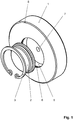
- Fig. 1
- Explosionsansicht einer Vorrichtung
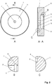
- Fig. 2
- Draufsicht und Schnitt A-A durch eine Vorrichtung mit Detail B und C
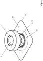
- Fig. 3
- Vorrichtung mit einer aufsetzbaren Basisplatte
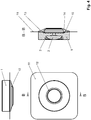
- Fig. 4
- Vorrichtung mit aufgesetzter Basisplatte
- Bei dem nach den
Fig. 1 bis 4 beschriebenen Ausführungsbeispiel handelt es sich um eine mögliche Variante einer Vorrichtung für eine Basisplatte 10 bei zweiteiligen Stomavorrichtungen, bei denen auf einer Hautschutzunterlage 14 ein Kopplungring 12 aus Kunststoff befestigt ist. Der Kopplungsring 12 hat einen Durchmesser von etwa 50 mm, ist einige mm breit und steht etwa 2,5 mm über der Hautschutzunterlage 14 vor. Auf der Hautschutzunterlage 14 ist eine etwa 30 mm breite Spezialkleberschicht 13 aufgebracht, der um das Stoma auf die Haut zu kleben ist. - Die
Fig. 1 undFig. 2 zeigen eine erfindungsgemäße Vorrichtung, bei der eine Wärmespeicherplatte 1 an der Basisplatte 10 abgewandten Seite eine Aufnahmeöffnung 5 für ein Thermometer 2 besitzt. Die Wärmespeicherplatte 1 ist eine runde Platte aus einer Aluminiumlegierung, hier AlMg3, mit einem Durchmesser von 79 mm, einer Dicke von 19,5 mm und einer umlaufenden Abkantung 8. Diese Maße sind je nach Ausführung der eingesetzten Basisplatte 10 variabel anpassbar. Das Volumen der Wärmespeicherplatte 1 beträgt etwa 100 cm3. - Die eingesetzte Aluminiumlegierung ist metallisch gut leidend, korrosionsfrei und einfach bearbeitbar.
- Die
Fig. 3 zeigt eine Vorrichtung, wie sie auf eine Basisplatte 10 aufsetzbar ist. InFig. 4 ist eine auf die Basisplatte 10 aufgesetzte Vorrichtung in 2 Ansichten sowie im Schnitt B-B dargestellt. - Die Wärmespeicherplatte 1 funktioniert als Wärmespeicher. Da der eingesetzten Spezialkleber seine beste Klebewirkung bei Körpertemperatur besitzt, ist ein wasserdichtes Thermometer 2 eingebaut. Dadurch wird es möglich, die Temperatur genau im vorgeschriebenen Bereich zu halten.
- Das Thermometer 2 wird mit einem Sicherungsring 3 fixiert, der innen im Umfang der Aufnahmeöffnung 5 in einer in Detail B ersichtlichen Ringnut 6 angeordnet ist. Die Abmessungen sind dabei so bemessen, dass das Thermometer 2 fest in der Aufnahmeöffnung 5 sitzt und ein ungehinderter Temperaturaustausch ermöglicht wird.
- Der Kopplungsring 12 der Basisplatte 10 besitzt eine zylinderförmige Kontur. Bei manchen Kopplungsringen 12 ist diese Kontur auch seitlich stufig oder nach außen hin abgeflacht ausgebildet und bildet einen Überstand 14.
- Auf der Gegenseite der Wärmespeicherplatte 1 ist deshalb eine auf den Überstand 14 des Kopplungsringes 12 der Basisplatte 10 abgestimmte Profilaussparung 4 eingearbeitet. Dementsprechend ist die Kontur der Aufnahmeöffnung 5 auch korrespondierend mit einer Profilierung 9 ausgebildet. Im Schnitt A-A ist eine zylinderförmige Kontur abgebildet. Das Detail C zeigt beispielsweise eine abgestufte Kontur. Die Profilaussparung 4 ist entsprechend der Höhe des Kopplungsringes 12 der Basisplatte 10 hier 2,5 mm tief.
- Vorteilhaft ist es, wenn das eingearbeitete Profil in der Wärmespeicherplatte 1 und die äußere Kontur der Basisplatte 10 nahezu identisch sind. Das führt dazu, dass beim Drücken mit der Wärmespeicherplatte 1 auf die Basisplatte 10 gleichzeitig die gesamte Fläche der Spezialkleberschicht 13 auf den Körper gedrückt wird. Damit wird verhindert, dass sich an der Klebefläche nicht die kleinsten Falten bilden können.
- In der Wärmespeicherplatte 1 ist eine durchgehende Entwässerungsbohrung 7 enthalten, die in die Aufnahmeöffnung 5 mündet und durch die enthaltenes Wasser leicht selbst entweichen oder ausgeschüttelt werden kann.
- Außerhalb der runden, direkten Spezialkleberschicht 13 ist die Hautschutzunterlage 11 zusätzlich mit einer selbsthaftenden Beschichtung versehen, die eine geringere Klebefähigkeit besitz. Diese ist rechteckig ausgebildet und mit einem Schutzpapier versehen, ähnlich wie bei einem handelsüblichen Heftpflaster.
- Die Vorgehensweise beim Anbringen einer Basisplatte 10 bei einem zweiteiligen Kopplungssystem mit Hilfe der erfindungsgemäßen Vorrichtung ist wie folgt:
Das Stomaversorgungssystem besteht aus einer separaten Basisplatte 10 als Hautschutz und einem Auffangbeutel. An beiden Teilen ist ein rastbarer Kopplungsring 12 befestigt, über den sie miteinander verbunden werden. - Nach der Reinigung und der Trocknung der peristomalen Haut um das Stoma wird der Hautschutz vorbereitet. Entweder der Hautschutz wird zugeschnitten oder bei modellierbarem Hautschutz entsprechend angepasst. Das Schutzpapier wird entfernt und die Basisplatte 10 wird nach Vorschrift des jeweiligen Herstellers aufgeklebt.
- Um die eingesetzte Basisplatte 10 sicher und fest mit der Klebefläche der Spezialkleberschicht 13 um das Stoma aufzukleben, ist die Temperatur der Klebefläche äußerst wichtig. Bei kalter Haut oder bei kalten Umgebungstemperaturen dauert es sehr lange, bis sich die Spezialkleberschicht 13 erwärmt bzw. die Körpertemperatur annimmt. Das ist aber gerade die Voraussetzung dafür, dass der Spezialkleber seine beste Klebefähigkeit entfaltet.
- Mit einem Warmwasserstrahl erwärmt man die Wärmespeicherplatte 1 auf ca. 40 Grad Celsius. Diese Temperatur wird auf dem Thermometer 2 angezeigt und kann von der betroffenen Person abgelesen werden. Nun wird die erwärmte Wärmespeicherplatte 1 mit der Seite der eingearbeiteten Profilaussparung 4 auf die am Körper befestigte Basisplatte 10 gedrückt. Nach etwa zwei Minuten hat die Klebefläche der Basisplatte durch die von der Wärmespeicherplatte 1 übertragene Wärme die Körpertemperatur und nach weiteren 2 Minuten etwa 34°C erreicht. Die Vorrichtung kann nun abgenommen werden. Ein festes Andrücken über die gesamte runde Fläche der Spezialkleberschicht 13 der Basisplatte 10 ermöglicht eine faltenfreie und dauerhafte Befestigung auf der Haut des Betroffenen.
- Als günstig und ausreichend hat sich erwiesen, wenn die auf 40°C erwärmte Wärmespeicherplatte 1 bezüglich ihrer Eigenschaften zur Wärmespeicherung und Wärmeabgabe so gewählt wird, dass der Zeitraum, in dem sich die Wärmespeicherplatte 1 um 5°C abkühlt mehr als 2 min dauert. Die Wärmespeicherplatte 1 sollte aus Handhabungs- und Gewichtsgründen so klein wie möglich sei. Sie ist jedoch so groß zu wählen, dass ausreichend viel Wärmeenergie aufgenommen und ausreichend Wärme mindestens 2 min gehalten werden kann, bis sie unter die Körpertemperatur sinkt.
- Die eingesetzte Wärmespeicherplatte 1 erfüllt bei der im vorliegenden Beispiel verwendeten Dimensionierung und dem hier eingesetzten Material die erforderlichen Bedingungen. Bei einem Volumen von etwa 100 cm3, einer Masse von ca. 270 g und einer spezifischen Wärmekapazität der Aluminiumlegierung von c = 0,89 kj (kg K)_1 wird sie bei 5 Grad Abkühlung eine Wärmemenge von etwa 0,3 Wh abgeben. Dabei wird in der Einsatzzeit bei der Abkühlung durch die aufgelegte Hand sowie die Wärmestrahlung und Wärmeströmung durch die Umgebung ein Wärmestrom von mehr als 2 W übertragen.
- Noch optimaler ist es, wenn eine Abkühlung um 10°C von 40°C auf etwa 30°C erfolgt, da die eingesetzten Spezialkleber noch besser aushärten können und die Klebeeigenschaften dadurch noch verbessert werden. Es liegt im Ermessen des Anwenders, einen für ihn hinsichtlich verfügbarer Zeit und Klebewirkung optimalen Bereich zu finden.
- Der Anwender kann die Temperatur sowohl bei der Aufheizung der Wärmespeicherplatte 1 als auch beim Aufdrücken der Wärmespeicherplatte 1 auf die Basisplatte genau verfolgen. Eventuell sich in der Aufnahmeöffnung 5 befindliches Restwasser kann durch die Entwässerungsbohrung 7 entweichen bzw. leicht ausgeschüttelt werden. Ein wasserdichtes und korrosionsfreies Gehäuse des Thermometers 2 garantiert eine lange Lebensdauer.
- Anschließend ist der Auffangbeutel nach den Hinweisen des Herstellers anzubringen.
- Durch diese Vorgehensweise wird eine dauerhafte und größtmögliche Haftung der Verbindung zwischen Körper und Basisplatte 10 geschaffen.
-
- 1
- Wärmespeicherplatte
- 2
- Thermometer
- 3
- Sicherungsring
- 4
- Profilaussparung
- 5
- Aufnahmeöffnung
- 6
- Ringnut
- 7
- Entwässerungsbohrung
- 8
- Abkantung
- 9
- Profilierung
- 10
- Basisplatte
- 11
- Hautschutzunterlage
- 12
- Kopplungsring
- 13
- Spezialkleberschicht
- 14
- Überstand
Claims (11)
- Vorrichtung zur Befestigung einer Basisplatte von Stomavorrichtungen mit zweiteiligen Kopplungssystemen, die aus einem abnehmbaren Beutel und einer separaten selbsthaftenden Basisplatte bestehen, auf der Haut von betroffenen Personen, wobei die Vorrichtung aus einer Wärmespeicherplatte (1) besteht, die an der bei der Verwendung der Vorrichtung der Basisplatte (10) abgewandten Seite eine Aufnahmeöffnung (5) für ein Thermometer (2) besitzt, und wobei Mittel zur Fixierung des Thermometers (2) in der Aufnahmeöffnung (5) vorhanden sind, dadurch gekennzeichnet, dass an der Basisplatte (10) zugewandten Seite der Wärmespeicherplatte (1) eine Profilaussparung (4) in die Wärmespeicherplatte (1) eingearbeitet ist, wobei die Profilaussparung (4) im Wesentlichen der äußeren Kontur eines an der Basisplatte (10) vorhandenen Überstandes (14) zur Kopplung mit dem Beutel entspricht und deren Tiefe minimal der Höhe dieses Überstandes (14) entspricht, und dass die Wärmespeicherplatte (1) so ausgewählt wird, dass bei der Anwendung der Vorrichtung die Temperaturabsenkung an der Oberfläche der Wärmespeicherplatte (1) innerhalb von 2 min nicht mehr als 5°C beträgt.
- Vorrichtung nach Anspruch 1, dadurch gekennzeichnet, dass die Wärmespeicherplatte (1) bei einer Temperaturabsenkung von 5°C eine Wärmemenge von mindestens 0,3 Wh abgeben kann.
- Vorrichtung nach Anspruch 1 und 2, dadurch gekennzeichnet, dass die Wärmespeicherplatte (1) aus Metall besteht.
- Vorrichtung nach Anspruch 3, dadurch gekennzeichnet, dass die Wärmespeicherplatte (1) aus Edelstahl oder Aluminium oder einer Aluminiumlegierung besteht.
- Vorrichtung nach einem der Ansprüche 1 bis 4, dadurch gekennzeichnet, dass die Wärmespeicherplatte (1) ein Volumen von mehr als 50 cm3 besitzt.
- Vorrichtung nach einem der Ansprüche 1 bis 5, dadurch gekennzeichnet, dass alle eingesetzten Teile aus bleifreien Materialien bestehen, wasserdicht sowie harz- und säurefest sind.
- Vorrichtung nach einem der Ansprüche 1 bis 6, dadurch gekennzeichnet, dass die Grundfläche der Wärmespeicherplatte (1) der dem Körper zugewandten Fläche einer Spezialkleberschicht (13) der Basisplatte (10) entspricht.
- Vorrichtung nach einem der Ansprüche 1 bis 7, dadurch gekennzeichnet, dass als Mittel zur Fixierung des Thermometers (2) in der Aufnahmeöffnung (5) im Umfang der Aufnahmeöffnung (5) eine Ringnut (6) für einen Sicherungsring (3) enthalten ist.
- Vorrichtung nach einem der Ansprüche 1 bis 8, dadurch gekennzeichnet, dass in der Wärmespeicherplatte (1) eine Entwässerungsbohrung (7) enthalten ist, die in die Aufnahmeöffnung (5) mündet.
- Vorrichtung nach einem der Ansprüche 1 bis 9, dadurch gekennzeichnet, dass als Mittel zur Fixierung des Thermometers (2) in der Aufnahmeöffnung (5) ein wärmeleitender Kleber eingesetzt wird.
- Verfahren zur Anwendung einer Vorrichtung nach einem der Ansprüche 1 bis 10, dadurch gekennzeichnet, dass die Vorrichtung mit einer auf etwa 40°C erwärmten Wärmespeicherplatte (1) mindestens 2 min auf die Rückseite einer mit einer Spezialkleberschicht (13) belegten Basisplatte (10) einer Stomavorrichtung gelegt wird bis das enthaltene Thermometer (2) als Temperatur der Spezialkleberschicht (13) die Körpertemperatur anzeigt und die Vorrichtung nach Abkühlung der Wärmespeicherplatte (1) auf der Anzeige des Thermometers (2) um mindestens 5°C wieder entfernt wird.
Applications Claiming Priority (1)
| Application Number | Priority Date | Filing Date | Title |
|---|---|---|---|
| DE102018126465.8A DE102018126465B4 (de) | 2018-10-24 | 2018-10-24 | Verwendung einer Vorrichtung mit einer Wärmespeicherplatte zur Befestigung einer Basisplatte von Stomavorrichtungen mit zweiteiligen Kopplungssystemen |
Publications (2)
| Publication Number | Publication Date |
|---|---|
| EP3643224A1 EP3643224A1 (de) | 2020-04-29 |
| EP3643224B1 true EP3643224B1 (de) | 2021-05-05 |
Family
ID=68342785
Family Applications (1)
| Application Number | Title | Priority Date | Filing Date |
|---|---|---|---|
| EP19205066.4A Active EP3643224B1 (de) | 2018-10-24 | 2019-10-24 | Vorrichtung zur befestigung einer basisplatte von stomavorrichtungen sowie ein verfahren zu deren anwendung |
Country Status (2)
| Country | Link |
|---|---|
| EP (1) | EP3643224B1 (de) |
| DE (1) | DE102018126465B4 (de) |
Families Citing this family (4)
| Publication number | Priority date | Publication date | Assignee | Title |
|---|---|---|---|---|
| US11590017B2 (en) | 2019-04-25 | 2023-02-28 | Convatec Technologies Inc. | Ostomy wafers incorporating adhesives, ostomy devices including the same, and methods of applying ostomy wafers and ostomy devices |
| BR112021021315A2 (pt) | 2019-04-25 | 2022-01-18 | Convatec Technologies Inc | Placas de ostomia incorporando adesivos e camadas de espuma, dispositivos incluindo as mesmas e métodos de aplicação |
| SG11202111675TA (en) | 2019-04-25 | 2021-11-29 | Convatec Technologies Inc | Perforated chamber ostomy wafers,devices including the same, and methods of applying |
| GB2594506A (en) * | 2020-04-30 | 2021-11-03 | Ostique Ltd | Coupling system |
Citations (1)
| Publication number | Priority date | Publication date | Assignee | Title |
|---|---|---|---|---|
| JPS5398664U (de) * | 1977-01-12 | 1978-08-10 |
Family Cites Families (7)
| Publication number | Priority date | Publication date | Assignee | Title |
|---|---|---|---|---|
| GB1021145A (en) | 1963-03-18 | 1966-03-02 | John Leslie Russell | Colostomy, ileostomy and ureterostomy appliance |
| US4784656A (en) * | 1985-05-02 | 1988-11-15 | Christian Delores J | Fecal incontinence receptacle and methods of use |
| FR2605879B1 (fr) | 1986-10-31 | 1994-01-28 | Biotrol Laboratoires | Dispositif perfectionne d'ostomie |
| US4710182A (en) | 1986-12-04 | 1987-12-01 | Hollister Incorporated | Ostomy appliance and method of making |
| GB2290974B (en) * | 1995-08-01 | 1996-06-19 | Squibb & Sons Inc | Body-side ostomy member |
| PL1711147T3 (pl) * | 2004-01-27 | 2011-06-30 | Coloplast As | Produkt absorbujący ze strefami o różnych właściwościach powierzchni |
| US20070185464A1 (en) * | 2006-02-03 | 2007-08-09 | Bristol-Myers Squibb Company | Ostomy appliance with recovery resistant moldable adhesive |
-
2018
- 2018-10-24 DE DE102018126465.8A patent/DE102018126465B4/de not_active Expired - Fee Related
-
2019
- 2019-10-24 EP EP19205066.4A patent/EP3643224B1/de active Active
Patent Citations (1)
| Publication number | Priority date | Publication date | Assignee | Title |
|---|---|---|---|---|
| JPS5398664U (de) * | 1977-01-12 | 1978-08-10 |
Also Published As
| Publication number | Publication date |
|---|---|
| DE102018126465B4 (de) | 2022-02-17 |
| EP3643224A1 (de) | 2020-04-29 |
| DE102018126465A1 (de) | 2020-04-30 |
Similar Documents
| Publication | Publication Date | Title |
|---|---|---|
| EP3643224B1 (de) | Vorrichtung zur befestigung einer basisplatte von stomavorrichtungen sowie ein verfahren zu deren anwendung | |
| DE2549169C2 (de) | Stützschiene für ein Körperglied und seine zugehörige Extremität | |
| EP3484423B1 (de) | Vorrichtung zur hyperthermischen behandlung von juckreiz | |
| AT519279A1 (de) | Vorrichtung zur Kühlung einer Körperregion | |
| DE202010013176U1 (de) | Schutzeinrichtung für den diabetischen Fuß | |
| WO2007082648A1 (de) | Handgerät und verfahren zum thermischen behandeln der durch einen insektenstich oder -biss betroffenen stelle | |
| EP3784327A1 (de) | Elektrodenkörper einer elektrodenanordnung und elektrodenanordnung zur elektrischen stimulation sowie verfahren zur herstellung einer elektrodenanordnung | |
| EP2654478A1 (de) | SCHUTZEINRICHTUNG FÜR DEN DIABETISCHEN FUß UND VERFAHREN ZUM SCHUTZ DES DIABETISCHEN FUßES VOR FEHLENDER DURCHBLUTUNG | |
| DE202012102017U1 (de) | Vorrichtung zum Vorspannen einer Konusverbindung | |
| DE20314527U1 (de) | Medizinsche Hautabdeckung, insbesondere Pflaster | |
| AT515080B1 (de) | Vorrichtung zum Kühlen eines Körpers oder eines Körperteils für medizinische oder leistungssteigernde Zwecke | |
| AT512305A4 (de) | Vorrichtung und Verfahren zur Herstellung einer an einen Fuß bzw. ein Bein eines Benutzers angepassten Schale eines Schischuhs | |
| DE3131463C2 (de) | Elektrische Kochplatte mit einem metallischen Kochplattenkörper | |
| DE202018106079U1 (de) | Vorrichtung zur Befestigung einer Basisplatte bei Stomavorrichtungen mit zweiteiligen Kopplungssystemen | |
| DE102021125746A1 (de) | Flexible Kalt- und Warmkompresse | |
| EP3397106B1 (de) | Vorrichtung und verfahren zum anpassen der schale eines skischuhs zu einem fuss | |
| DE102016104877B4 (de) | Orthopädietechnische Einrichtung | |
| WO2017097906A1 (de) | Grosszehengrundgelenksersatz, insbesondere auf keramischer basis | |
| EP2386265A1 (de) | Transportvorrichtung zur Fixierung von thermisch vorbehandelten Mittelohrprothesen aus Memory-Metall mit Platzhalter-Pins | |
| DE102014018814A1 (de) | Ostomievorrichtung und Abstandshalter für eine Ostomievorrichtung | |
| WO2023066429A1 (de) | Verfahren zur herstellung einer vorrichtung zum schutz eines körperteils und vorrichtung | |
| DE102021119872A1 (de) | Kühlpad, Kühlvorrichtung, Kühlsystem sowie Verfahren zum Betrieb eines Kühlpads und einer Kühlvorrichtung | |
| EP0035584B1 (de) | Ein Kissen enthaltender Druckverband | |
| DE202009011309U1 (de) | Vorrichtung zum elektrischen Erfassen der Wärmeabgabe eines Heizkörpers | |
| DE202020100340U1 (de) | Wärmeabsorbierende Fixierung zum transkutanen Aufladen eines implantierten medizinischen Geräts |
Legal Events
| Date | Code | Title | Description |
|---|---|---|---|
| PUAI | Public reference made under article 153(3) epc to a published international application that has entered the european phase |
Free format text: ORIGINAL CODE: 0009012 |
|
| STAA | Information on the status of an ep patent application or granted ep patent |
Free format text: STATUS: REQUEST FOR EXAMINATION WAS MADE |
|
| 17P | Request for examination filed |
Effective date: 20200113 |
|
| AK | Designated contracting states |
Kind code of ref document: A1 Designated state(s): AL AT BE BG CH CY CZ DE DK EE ES FI FR GB GR HR HU IE IS IT LI LT LU LV MC MK MT NL NO PL PT RO RS SE SI SK SM TR |
|
| AX | Request for extension of the european patent |
Extension state: BA ME |
|
| STAA | Information on the status of an ep patent application or granted ep patent |
Free format text: STATUS: EXAMINATION IS IN PROGRESS |
|
| 17Q | First examination report despatched |
Effective date: 20200901 |
|
| GRAP | Despatch of communication of intention to grant a patent |
Free format text: ORIGINAL CODE: EPIDOSNIGR1 |
|
| STAA | Information on the status of an ep patent application or granted ep patent |
Free format text: STATUS: GRANT OF PATENT IS INTENDED |
|
| INTG | Intention to grant announced |
Effective date: 20210129 |
|
| GRAS | Grant fee paid |
Free format text: ORIGINAL CODE: EPIDOSNIGR3 |
|
| GRAA | (expected) grant |
Free format text: ORIGINAL CODE: 0009210 |
|
| STAA | Information on the status of an ep patent application or granted ep patent |
Free format text: STATUS: THE PATENT HAS BEEN GRANTED |
|
| AK | Designated contracting states |
Kind code of ref document: B1 Designated state(s): AL AT BE BG CH CY CZ DE DK EE ES FI FR GB GR HR HU IE IS IT LI LT LU LV MC MK MT NL NO PL PT RO RS SE SI SK SM TR |
|
| REG | Reference to a national code |
Ref country code: GB Ref legal event code: FG4D Free format text: NOT ENGLISH |
|
| REG | Reference to a national code |
Ref country code: CH Ref legal event code: EP |
|
| REG | Reference to a national code |
Ref country code: AT Ref legal event code: REF Ref document number: 1388770 Country of ref document: AT Kind code of ref document: T Effective date: 20210515 |
|
| REG | Reference to a national code |
Ref country code: IE Ref legal event code: FG4D Free format text: LANGUAGE OF EP DOCUMENT: GERMAN |
|
| REG | Reference to a national code |
Ref country code: DE Ref legal event code: R096 Ref document number: 502019001370 Country of ref document: DE |
|
| REG | Reference to a national code |
Ref country code: LT Ref legal event code: MG9D |
|
| PG25 | Lapsed in a contracting state [announced via postgrant information from national office to epo] |
Ref country code: LT Free format text: LAPSE BECAUSE OF FAILURE TO SUBMIT A TRANSLATION OF THE DESCRIPTION OR TO PAY THE FEE WITHIN THE PRESCRIBED TIME-LIMIT Effective date: 20210505 Ref country code: HR Free format text: LAPSE BECAUSE OF FAILURE TO SUBMIT A TRANSLATION OF THE DESCRIPTION OR TO PAY THE FEE WITHIN THE PRESCRIBED TIME-LIMIT Effective date: 20210505 Ref country code: FI Free format text: LAPSE BECAUSE OF FAILURE TO SUBMIT A TRANSLATION OF THE DESCRIPTION OR TO PAY THE FEE WITHIN THE PRESCRIBED TIME-LIMIT Effective date: 20210505 Ref country code: BG Free format text: LAPSE BECAUSE OF FAILURE TO SUBMIT A TRANSLATION OF THE DESCRIPTION OR TO PAY THE FEE WITHIN THE PRESCRIBED TIME-LIMIT Effective date: 20210805 |
|
| PG25 | Lapsed in a contracting state [announced via postgrant information from national office to epo] |
Ref country code: RS Free format text: LAPSE BECAUSE OF FAILURE TO SUBMIT A TRANSLATION OF THE DESCRIPTION OR TO PAY THE FEE WITHIN THE PRESCRIBED TIME-LIMIT Effective date: 20210505 Ref country code: PT Free format text: LAPSE BECAUSE OF FAILURE TO SUBMIT A TRANSLATION OF THE DESCRIPTION OR TO PAY THE FEE WITHIN THE PRESCRIBED TIME-LIMIT Effective date: 20210906 Ref country code: SE Free format text: LAPSE BECAUSE OF FAILURE TO SUBMIT A TRANSLATION OF THE DESCRIPTION OR TO PAY THE FEE WITHIN THE PRESCRIBED TIME-LIMIT Effective date: 20210505 Ref country code: PL Free format text: LAPSE BECAUSE OF FAILURE TO SUBMIT A TRANSLATION OF THE DESCRIPTION OR TO PAY THE FEE WITHIN THE PRESCRIBED TIME-LIMIT Effective date: 20210505 Ref country code: LV Free format text: LAPSE BECAUSE OF FAILURE TO SUBMIT A TRANSLATION OF THE DESCRIPTION OR TO PAY THE FEE WITHIN THE PRESCRIBED TIME-LIMIT Effective date: 20210505 Ref country code: NO Free format text: LAPSE BECAUSE OF FAILURE TO SUBMIT A TRANSLATION OF THE DESCRIPTION OR TO PAY THE FEE WITHIN THE PRESCRIBED TIME-LIMIT Effective date: 20210805 Ref country code: IS Free format text: LAPSE BECAUSE OF FAILURE TO SUBMIT A TRANSLATION OF THE DESCRIPTION OR TO PAY THE FEE WITHIN THE PRESCRIBED TIME-LIMIT Effective date: 20210905 Ref country code: GR Free format text: LAPSE BECAUSE OF FAILURE TO SUBMIT A TRANSLATION OF THE DESCRIPTION OR TO PAY THE FEE WITHIN THE PRESCRIBED TIME-LIMIT Effective date: 20210806 |
|
| REG | Reference to a national code |
Ref country code: NL Ref legal event code: MP Effective date: 20210505 |
|
| PG25 | Lapsed in a contracting state [announced via postgrant information from national office to epo] |
Ref country code: NL Free format text: LAPSE BECAUSE OF FAILURE TO SUBMIT A TRANSLATION OF THE DESCRIPTION OR TO PAY THE FEE WITHIN THE PRESCRIBED TIME-LIMIT Effective date: 20210505 |
|
| PG25 | Lapsed in a contracting state [announced via postgrant information from national office to epo] |
Ref country code: SK Free format text: LAPSE BECAUSE OF FAILURE TO SUBMIT A TRANSLATION OF THE DESCRIPTION OR TO PAY THE FEE WITHIN THE PRESCRIBED TIME-LIMIT Effective date: 20210505 Ref country code: ES Free format text: LAPSE BECAUSE OF FAILURE TO SUBMIT A TRANSLATION OF THE DESCRIPTION OR TO PAY THE FEE WITHIN THE PRESCRIBED TIME-LIMIT Effective date: 20210505 Ref country code: EE Free format text: LAPSE BECAUSE OF FAILURE TO SUBMIT A TRANSLATION OF THE DESCRIPTION OR TO PAY THE FEE WITHIN THE PRESCRIBED TIME-LIMIT Effective date: 20210505 Ref country code: CZ Free format text: LAPSE BECAUSE OF FAILURE TO SUBMIT A TRANSLATION OF THE DESCRIPTION OR TO PAY THE FEE WITHIN THE PRESCRIBED TIME-LIMIT Effective date: 20210505 Ref country code: DK Free format text: LAPSE BECAUSE OF FAILURE TO SUBMIT A TRANSLATION OF THE DESCRIPTION OR TO PAY THE FEE WITHIN THE PRESCRIBED TIME-LIMIT Effective date: 20210505 Ref country code: RO Free format text: LAPSE BECAUSE OF FAILURE TO SUBMIT A TRANSLATION OF THE DESCRIPTION OR TO PAY THE FEE WITHIN THE PRESCRIBED TIME-LIMIT Effective date: 20210505 Ref country code: SM Free format text: LAPSE BECAUSE OF FAILURE TO SUBMIT A TRANSLATION OF THE DESCRIPTION OR TO PAY THE FEE WITHIN THE PRESCRIBED TIME-LIMIT Effective date: 20210505 |
|
| REG | Reference to a national code |
Ref country code: DE Ref legal event code: R097 Ref document number: 502019001370 Country of ref document: DE |
|
| PGFP | Annual fee paid to national office [announced via postgrant information from national office to epo] |
Ref country code: FR Payment date: 20211021 Year of fee payment: 3 |
|
| PLBE | No opposition filed within time limit |
Free format text: ORIGINAL CODE: 0009261 |
|
| STAA | Information on the status of an ep patent application or granted ep patent |
Free format text: STATUS: NO OPPOSITION FILED WITHIN TIME LIMIT |
|
| 26N | No opposition filed |
Effective date: 20220208 |
|
| PG25 | Lapsed in a contracting state [announced via postgrant information from national office to epo] |
Ref country code: IS Free format text: LAPSE BECAUSE OF FAILURE TO SUBMIT A TRANSLATION OF THE DESCRIPTION OR TO PAY THE FEE WITHIN THE PRESCRIBED TIME-LIMIT Effective date: 20210905 Ref country code: AL Free format text: LAPSE BECAUSE OF FAILURE TO SUBMIT A TRANSLATION OF THE DESCRIPTION OR TO PAY THE FEE WITHIN THE PRESCRIBED TIME-LIMIT Effective date: 20210505 |
|
| REG | Reference to a national code |
Ref country code: BE Ref legal event code: MM Effective date: 20211031 |
|
| PG25 | Lapsed in a contracting state [announced via postgrant information from national office to epo] |
Ref country code: MC Free format text: LAPSE BECAUSE OF FAILURE TO SUBMIT A TRANSLATION OF THE DESCRIPTION OR TO PAY THE FEE WITHIN THE PRESCRIBED TIME-LIMIT Effective date: 20210505 |
|
| PG25 | Lapsed in a contracting state [announced via postgrant information from national office to epo] |
Ref country code: BE Free format text: LAPSE BECAUSE OF NON-PAYMENT OF DUE FEES Effective date: 20211031 Ref country code: LU Free format text: LAPSE BECAUSE OF NON-PAYMENT OF DUE FEES Effective date: 20211024 |
|
| PG25 | Lapsed in a contracting state [announced via postgrant information from national office to epo] |
Ref country code: IE Free format text: LAPSE BECAUSE OF NON-PAYMENT OF DUE FEES Effective date: 20211024 |
|
| PGFP | Annual fee paid to national office [announced via postgrant information from national office to epo] |
Ref country code: IT Payment date: 20221031 Year of fee payment: 4 Ref country code: DE Payment date: 20220912 Year of fee payment: 4 |
|
| REG | Reference to a national code |
Ref country code: CH Ref legal event code: PL |
|
| PG25 | Lapsed in a contracting state [announced via postgrant information from national office to epo] |
Ref country code: CY Free format text: LAPSE BECAUSE OF FAILURE TO SUBMIT A TRANSLATION OF THE DESCRIPTION OR TO PAY THE FEE WITHIN THE PRESCRIBED TIME-LIMIT Effective date: 20210505 |
|
| PG25 | Lapsed in a contracting state [announced via postgrant information from national office to epo] |
Ref country code: LI Free format text: LAPSE BECAUSE OF NON-PAYMENT OF DUE FEES Effective date: 20221031 Ref country code: HU Free format text: LAPSE BECAUSE OF FAILURE TO SUBMIT A TRANSLATION OF THE DESCRIPTION OR TO PAY THE FEE WITHIN THE PRESCRIBED TIME-LIMIT; INVALID AB INITIO Effective date: 20191024 Ref country code: FR Free format text: LAPSE BECAUSE OF NON-PAYMENT OF DUE FEES Effective date: 20221031 Ref country code: CH Free format text: LAPSE BECAUSE OF NON-PAYMENT OF DUE FEES Effective date: 20221031 |
|
| PG25 | Lapsed in a contracting state [announced via postgrant information from national office to epo] |
Ref country code: MK Free format text: LAPSE BECAUSE OF FAILURE TO SUBMIT A TRANSLATION OF THE DESCRIPTION OR TO PAY THE FEE WITHIN THE PRESCRIBED TIME-LIMIT Effective date: 20210505 |
|
| REG | Reference to a national code |
Ref country code: DE Ref legal event code: R119 Ref document number: 502019001370 Country of ref document: DE |
|
| GBPC | Gb: european patent ceased through non-payment of renewal fee |
Effective date: 20231024 |
|
| PG25 | Lapsed in a contracting state [announced via postgrant information from national office to epo] |
Ref country code: TR Free format text: LAPSE BECAUSE OF FAILURE TO SUBMIT A TRANSLATION OF THE DESCRIPTION OR TO PAY THE FEE WITHIN THE PRESCRIBED TIME-LIMIT Effective date: 20210505 |
|
| PG25 | Lapsed in a contracting state [announced via postgrant information from national office to epo] |
Ref country code: GB Free format text: LAPSE BECAUSE OF NON-PAYMENT OF DUE FEES Effective date: 20231024 |
|
| PG25 | Lapsed in a contracting state [announced via postgrant information from national office to epo] |
Ref country code: GB Free format text: LAPSE BECAUSE OF NON-PAYMENT OF DUE FEES Effective date: 20231024 Ref country code: DE Free format text: LAPSE BECAUSE OF NON-PAYMENT OF DUE FEES Effective date: 20240501 |
|
| PG25 | Lapsed in a contracting state [announced via postgrant information from national office to epo] |
Ref country code: MT Free format text: LAPSE BECAUSE OF FAILURE TO SUBMIT A TRANSLATION OF THE DESCRIPTION OR TO PAY THE FEE WITHIN THE PRESCRIBED TIME-LIMIT Effective date: 20210505 |
|
| PG25 | Lapsed in a contracting state [announced via postgrant information from national office to epo] |
Ref country code: IT Free format text: LAPSE BECAUSE OF NON-PAYMENT OF DUE FEES Effective date: 20231024 |
|
| PG25 | Lapsed in a contracting state [announced via postgrant information from national office to epo] |
Ref country code: IT Free format text: LAPSE BECAUSE OF NON-PAYMENT OF DUE FEES Effective date: 20231024 |
|
| REG | Reference to a national code |
Ref country code: AT Ref legal event code: MM01 Ref document number: 1388770 Country of ref document: AT Kind code of ref document: T Effective date: 20241024 |
|
| PG25 | Lapsed in a contracting state [announced via postgrant information from national office to epo] |
Ref country code: AT Free format text: LAPSE BECAUSE OF NON-PAYMENT OF DUE FEES Effective date: 20241024 |
|
| PGFP | Annual fee paid to national office [announced via postgrant information from national office to epo] |
Ref country code: AT Payment date: 20260410 Year of fee payment: 5 |