EP3643374A1 - Fixation de ski de randonnée - Google Patents
Fixation de ski de randonnée Download PDFInfo
- Publication number
- EP3643374A1 EP3643374A1 EP19203517.8A EP19203517A EP3643374A1 EP 3643374 A1 EP3643374 A1 EP 3643374A1 EP 19203517 A EP19203517 A EP 19203517A EP 3643374 A1 EP3643374 A1 EP 3643374A1
- Authority
- EP
- European Patent Office
- Prior art keywords
- ski
- jaw
- toe
- guide
- piece
- Prior art date
- Legal status (The legal status is an assumption and is not a legal conclusion. Google has not performed a legal analysis and makes no representation as to the accuracy of the status listed.)
- Granted
Links
Images









Classifications
-
- A—HUMAN NECESSITIES
- A63—SPORTS; GAMES; AMUSEMENTS
- A63C—SKATES; SKIS; ROLLER SKATES; DESIGN OR LAYOUT OF COURTS, RINKS OR THE LIKE
- A63C9/00—Ski bindings
- A63C9/08—Ski bindings yieldable or self-releasing in the event of an accident, i.e. safety bindings
- A63C9/085—Ski bindings yieldable or self-releasing in the event of an accident, i.e. safety bindings with sole hold-downs, e.g. swingable
- A63C9/08507—Ski bindings yieldable or self-releasing in the event of an accident, i.e. safety bindings with sole hold-downs, e.g. swingable with a plurality of mobile jaws
- A63C9/08528—Ski bindings yieldable or self-releasing in the event of an accident, i.e. safety bindings with sole hold-downs, e.g. swingable with a plurality of mobile jaws pivoting about a longitudinal axis
-
- A—HUMAN NECESSITIES
- A63—SPORTS; GAMES; AMUSEMENTS
- A63C—SKATES; SKIS; ROLLER SKATES; DESIGN OR LAYOUT OF COURTS, RINKS OR THE LIKE
- A63C9/00—Ski bindings
- A63C9/08—Ski bindings yieldable or self-releasing in the event of an accident, i.e. safety bindings
- A63C9/085—Ski bindings yieldable or self-releasing in the event of an accident, i.e. safety bindings with sole hold-downs, e.g. swingable
- A63C9/08507—Ski bindings yieldable or self-releasing in the event of an accident, i.e. safety bindings with sole hold-downs, e.g. swingable with a plurality of mobile jaws
- A63C9/08521—Ski bindings yieldable or self-releasing in the event of an accident, i.e. safety bindings with sole hold-downs, e.g. swingable with a plurality of mobile jaws pivoting about a vertical axis, e.g. side release
-
- A—HUMAN NECESSITIES
- A63—SPORTS; GAMES; AMUSEMENTS
- A63C—SKATES; SKIS; ROLLER SKATES; DESIGN OR LAYOUT OF COURTS, RINKS OR THE LIKE
- A63C9/00—Ski bindings
- A63C9/08—Ski bindings yieldable or self-releasing in the event of an accident, i.e. safety bindings
- A63C9/085—Ski bindings yieldable or self-releasing in the event of an accident, i.e. safety bindings with sole hold-downs, e.g. swingable
- A63C9/08557—Details of the release mechanism
- A63C9/08564—Details of the release mechanism using cam or slide surface
-
- A—HUMAN NECESSITIES
- A63—SPORTS; GAMES; AMUSEMENTS
- A63C—SKATES; SKIS; ROLLER SKATES; DESIGN OR LAYOUT OF COURTS, RINKS OR THE LIKE
- A63C9/00—Ski bindings
- A63C9/08—Ski bindings yieldable or self-releasing in the event of an accident, i.e. safety bindings
- A63C9/085—Ski bindings yieldable or self-releasing in the event of an accident, i.e. safety bindings with sole hold-downs, e.g. swingable
- A63C9/08557—Details of the release mechanism
- A63C9/08571—Details of the release mechanism using axis and lever
-
- A—HUMAN NECESSITIES
- A63—SPORTS; GAMES; AMUSEMENTS
- A63C—SKATES; SKIS; ROLLER SKATES; DESIGN OR LAYOUT OF COURTS, RINKS OR THE LIKE
- A63C9/00—Ski bindings
- A63C9/08—Ski bindings yieldable or self-releasing in the event of an accident, i.e. safety bindings
- A63C9/0807—Ski bindings yieldable or self-releasing in the event of an accident, i.e. safety bindings for both towing and downhill skiing
-
- A—HUMAN NECESSITIES
- A63—SPORTS; GAMES; AMUSEMENTS
- A63C—SKATES; SKIS; ROLLER SKATES; DESIGN OR LAYOUT OF COURTS, RINKS OR THE LIKE
- A63C9/00—Ski bindings
- A63C9/08—Ski bindings yieldable or self-releasing in the event of an accident, i.e. safety bindings
- A63C9/086—Ski bindings yieldable or self-releasing in the event of an accident, i.e. safety bindings using parts which are fixed on the shoe of the user and are releasable from the ski binding
-
- A—HUMAN NECESSITIES
- A63—SPORTS; GAMES; AMUSEMENTS
- A63C—SKATES; SKIS; ROLLER SKATES; DESIGN OR LAYOUT OF COURTS, RINKS OR THE LIKE
- A63C9/00—Ski bindings
- A63C9/22—Arrangements for adjusting the toe-clamps
Definitions
- the present invention relates to the technical sector concerning ski bindings, with particular reference to a toe-piece of the ski binding.
- ski mountaineering toe-pieces of ski bindings which enable unhooking the ski boot during descent where there is a fall, or a twist of a foot, or in any case each time the ski boot transmits to the toe-piece of the ski binding a transversal force directed towards the outside, greater than a threshold value.
- EP1907078 which comprises: a base which is fixable to a ski; a first jaw; a second jaw; a first pin for inserting in a first lateral hole fashioned in the tip of a ski boot, which first pin is borne by the first jaw; a second pin for inserting in a second lateral hole opposite the first lateral hole fashioned in the tip of the ski boot, which second pin is borne by the second jaw.
- the first jaw and the second jaw are rotoidally coupled to the base by means of respective pins that are perpendicular to the base, in order to enable the toe-piece of the ski binding to be hooked or unhooked from the ski boot.
- the aim of the present invention consists in describing a toe-piece of a ski binding that offers an alternative to what is described in the foregoing.
- reference numeral (1) denotes in its entirety a toe-piece of the ski binding according to the present invention, comprising: a base (2) which is fixable to a ski; a first jaw (3); a second jaw (4); a first pin (5) for inserting in a first lateral hole fashioned in the tip of a ski boot, which first pin (5) is borne by the first jaw (3); a second pin (6) for inserting in a second lateral hole opposite the first lateral hole fashioned in the tip of the ski boot, which second pin (6) is borne by the second jaw (4); a first guide (7) which is borne by the base (2), which has a first portion (8) which extends away from the longitudinal axis of the ski, when the base (2) is fixed to the ski, and which has a second portion (9), following the first portion (8), which extends towards the front part of the ski, when the base (2) is fixed to the ski; a second guide (10) which is borne by the base (2), which has a third
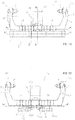
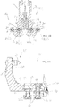
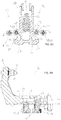
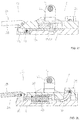
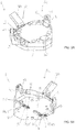
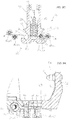
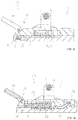
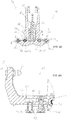
- the toe-piece of the ski binding (1) is configured so as to assume a first hooked configuration of the ski boot (A1), (see figures 1A-1L ), in order to hook the tip of a ski boot, wherein the first pin (5) and the second pin (6) are located away from one another by a first distance, wherein the first sliding element (14) and the second sliding element (15) are located in the first portion (8) of the first guide (7), and wherein the third sliding element (17) and the fourth sliding element (18) are located in the third portion (11) of the second guide (10); a first unhooked configuration of the ski boot (S1) (see figures 2A-2L ), for unhooking the tip of a ski boot, which first unhooked configuration of the ski boot (S1) is obtained starting from the first hooked configuration of the ski boot (A1) after the first couple of sliding elements (13) has carried out a first run along the first guide (7) and the second couple of sliding elements (16) has carried out a second run along the second guide (10) (compare figures 1B and 2B and
- the expression “move away transversally with respect to the longitudinal axis of the ski” is taken to mean that the ski boot moves away with respect to the longitudinal axis of the ski carrying out a movement which has at least one perpendicular component with respect to the longitudinal axis of the ski, when the base (2) is fixed to the ski.
- the second unhooked configuration of the ski boot is the automatic unhooked configuration of the ski boot during the descent, i.e. the configuration that the toe-piece of the ski binding (1) assumes in the case of impacts or urges on the toe-piece of the ski binding (1) or on the ski boot, which are translated into a first transversal force and directed towards the outside and/or into a second transversal force and directed towards the outside which acts on the first jaw (3) and/or on the second jaw (4) and which are/is of a higher intensity than a first threshold value and/or a second threshold value.
- first transversal force and directed outwards that is of a higher intensity than a first threshold value and/or a second transversal force directed outwards that is greater than the second threshold value.
- first transversal force and directed towards the outside are affected by the first transversal force and directed towards the outside, so only the first couple of sliding elements (13) performs a third run, drawing with it the respective jaw (3), while the other is practically stopped in the position assumed at the first hooked configuration of the ski boot (A1).
- the first couple of sliding elements (13) and the second couple of sliding elements (16) can respectively perform, one independently of the other, a third run and a fourth run, drawing the first jaw (3) and the second jaw (4), up to reaching the position they assume at the second unhooked configuration (S2) of the ski boot.
- the first jaw (3) is preferably C-shaped and comprises a first part (40) to which the first pin (5) is constrained and a second part (41) to which the first couple of sliding elements (13) is constrained (see figures 1A , 1C , 1D , 1H , 2A , 2C , 2D , 2H , 3A , 3C , 3H , 3D , 4A , 4C , 4D , and 4H ).
- the first pin (5) is preferably fixed to the first part (40).
- the first jaw (3) is preferably constrained to the base (2) so that only the sliding of the first couple of sliding elements (13) is enabled along the first guide (7) (see figures 1A , 1C , 1D , 1H , 2A , 2C , 2D , 2H , 3A , 3C , 3H , 3D , 4A , 4C , 4D , and 4H ).
- the first couple of sliding elements (13) preferably rolls along the first guide (7), to limit friction forces.
- the first couple of sliding elements (13) might slide along the first guide (7).
- the second jaw (4) is preferably C-shaped and comprises a third part (42) to which the second pin (6) is constrained and a fourth part (43) to which the second couple of sliding elements (16) is constrained (see figures 1A , 1C , 1D , 1H , 2A , 2C , 2D , 2H , 3A , 3C , 3H , 3D , 4A , 4C , 4D , and 4H ).
- the second pin (6) is preferably fixed to the third part (42).
- the second jaw (4) is preferably constrained to the base (2) so that only the sliding of the second couple of sliding elements (16) is enabled along the second guide (10) (see figures 1A , 1C , 1D , 1H , 2A , 2C , 2D , 2H , 3A , 3C , 3H , 3D , 4A , 4C , 4D , and 4H ).
- the second couple of sliding elements (16) preferably rolls along the second guide (10), to limit friction forces.
- the second couple of sliding elements (16) might slide along the second guide (10).
- the first guide (7) and the second guide (10) are preferably fashioned in the base (2).
- the first guide (7) and the second guide (10) are each defined by a relative cut made in the base (2) and profiled so as to receive and guide, one following another, respectively, the first sliding element (14) and the second sliding element (15) and the third sliding element (17) and the fourth sliding element (18).
- the first guide (7) and the second guide (10) can be borne by the base (2), for example can be guide rails or rails of various types, fixed to the base (2) to receive and guide, one following another, respectively, the first sliding element (14) and the second sliding element (15) and the third sliding element (17) and the fourth sliding element (18).
- the first jaw (3) is preferably coupled to the base (2) by means of the coupling between the first couple of sliding elements (13) and the first guide (7) so that the first jaw (3) can move parallel to the base (2).
- the second jaw (4) is preferably coupled to the base (2) by means of the coupling between the second couple of sliding elements (16) and the second guide (10) so that the second jaw (4) can move parallel to the base (2).
- the first guide (7) can preferably be a curved guide, so as to make the movement of the first couple of sliding elements (13) along the first guide (7) more fluid (see for example figures 1B , 1F , 2B , 2F , 3B , 3F , 4B , 4F ).
- the second guide (10) can preferably be a curved guide, so as to make the movement of the second couple of sliding elements (16) along the second guide (10) more fluid (see for example figures 1B , 1F , 2B , 2F , 3B , 3F , 4B , 4F ).
- the first guide (7) and the second guide (10) preferably have an L-shape with a bevelled corner.
- the L-shape is orientated in such a way that the first branch of the L-shape, which corresponds, respectively, to the first portion (8) and the third portion (11), extends in a substantially perpendicular way to the longitudinal axis of the ski, when the base (2) is fixed to the ski, and the second branch of the L-shape, which corresponds, respectively, to the second portion (9) and the fourth portion (12), extends, starting from the first branch, obliquely with respect to the longitudinal axis of the ski, when the base (2) is fixed to the ski, and is connected to the first branch by means of a connecting branch.
- the first guide (7) can extend along a broken line, in other words the first guide (7) can comprise at least a first fitting, interposed between the first portion (8) and the second portion (9) to connect them, or it can also include a first series of fittings interposed between the first portion (8) and the second portion (9) to connect them.
- the second guide (10) can extend along a broken line, in other words the second guide (10) can comprise at least a second fitting, interposed between the third portion (11) and the fourth portion (12) to connect them, or it can also include a second series of fittings interposed between the third portion (11) and the fourth portion (12) to connect them.
- the first portion (8) preferably extends in an arc of circumference having the relative centre at the region of space in which the heel of the ski boot rests on the heel-piece when the base (2) is fixed to the ski, to facilitate the unhooking of the ski boot starting from the first hooked configuration of the ski boot (A1).
- the third portion (11) preferably extends in an arc of circumference having the relative centre at the region of space in which the heel of the ski boot rests on the heel-piece when the base (2) is fixed to the ski, to facilitate the unhooking of the ski boot starting from the first hooked configuration of the ski boot (A1).
- the first portion (8) and the third portion (11) extend as two relative arcs of circumference having a radius that is substantially identical to the distance between the toe-piece of the ski binding (1) and the heel-piece for binding to the ski, when the when the base (2) is fixed to the ski.
- the arc of circumference conformation of the first portion (8) and the third portion (11) is advantageously such that, during the passage from the first hooked configuration of the ski boot (A1) to the second unhooked configuration of the ski boot (S2), the urges to which the ski boot will be subjected, and therefore the skier's foot, while the first couple of sliding elements (13) and/or the second couple of sliding elements (16) travel along the first portion (8) and/or/ the third portion (11) are reduced with respect to those which the ski boot will be subjected when travelling along a straight portion.
- the first portion (8) and the third portion (11) might be two straight segments.
- the first sliding element (14) preferably comprises a first rotatable roller (44).
- the first rotatable roller (44) is preferably rotatable with respect to an axis that is substantially perpendicular to the base (2).
- the first sliding element (14) preferably also comprises a first support (63) which is fixed to the first jaw (3) and which rotatably supports the first rotatable roller (44).
- the second sliding element (15) also preferably comprises a second rotatable roller (45) which is rotatable with respect to an axis that is substantially perpendicular to the base (2).
- the second sliding element (15) preferably also comprises a second support (64) which is fixed to the first jaw (3) and which rotatably supports the second rotatable roller (45) (see for example figures 1H , 2H , 3H and 4H ).
- the first rotatable roller (44) and the second rotatable roller (45) can advantageously roll along the first guide (7), reducing the friction forces, in passing from one configuration to another among those which the toe-piece of the ski binding (1) can assume.
- the third sliding element (17) preferably comprises a third rotatable roller (46).
- the third rotatable roller (46) is preferably rotatable with respect to an axis that is substantially perpendicular to the base (2).
- the third sliding element (17) preferably also comprises a third support (65) which is fixed to the second jaw (4) and which rotatably supports the third rotatable roller (46).
- the fourth sliding element (18) also preferably comprises a fourth rotatable roller (47) which is rotatable with respect to an axis that is substantially perpendicular to the base (2). Further, the fourth sliding element (18) preferably also comprises a fourth support (66) which is fixed to the second jaw (4) and which rotatably supports the fourth rotatable roller (47) (see for example figures 1H , 2H , 3H and 4H ).
- the third rotatable roller (46) and the fourth rotatable roller (47) can advantageously roll along the second guide (10), reducing the friction forces, in passing from one configuration to another among those which the toe-piece of the ski binding (1) can assume.
- the toe-piece of a ski binding (1) preferably comprises stabilising means (19) which are configured so as to maintain the toe-piece of the ski binding (1) in the first hooked configuration of the ski boot (A1) when the toe-piece of the ski binding (1) is in the first hooked configuration of the ski boot (A1).
- the toe-piece of the ski binding (1) is preferably configured in such a way that starting from the first hooked configuration of the ski boot (A1), when a first transversal force directed outwardly, which exceeds a first threshold value, acts on the first jaw (3) then the first couple of sliding elements (13) performs the third run along the first guide (7) and at least one from between the first sliding element (14) and the second sliding element (15) of the first couple of sliding elements (13) is arranged in the second portion (9) of the first guide (7), so that the toe-piece of the ski binding (1) reaches the second unhooked configuration of the ski boot (S2).
- the toe-piece of the ski binding (1) is configured in such a way that starting from the first hooked configuration of the ski boot (A1), when a second transversal force directed outwardly, which exceeds a second threshold value, acts on the second jaw (4), then the second couple of sliding elements (16) carries out the fourth run along the second guide (10) and at least one from between the third sliding element (17) and the fourth sliding element (18) of the second couple of sliding elements (16) is arranged in the fourth portion (12) of the second guide (10), so that the toe-piece of the ski binding (1) reaches the second unhooked configuration of the ski boot (S2).
- the stabilising means (19) are preferably designed so as to press against the first jaw (3) and against the second jaw (4) at least when the toe-piece of the ski binding (1) is in the first hooked configuration of the ski boot (A1), so that the first jaw (3) assumes a first stable balanced position (E1) along the first guide (7) or tends to reach the first stable balanced position (E1) after the first transversal force and directed outwardly, smaller than the first threshold value, has urged the first jaw (3), and so that the second jaw (4) assumes a second stable balanced position (E2) along the second guide (10) or tends to reach the second stable balanced position (E2) after the second transversal force and directed outwardly, smaller than the second threshold value, has urged the second jaw (4) (see figure 1E ).
- the stabilising means (19) advantageously make it such that the first jaw (3) and the second jaw (4) can move respectively from the first stable balanced position (E1) and from the second stable balanced position (E2) only if subjected to an outside force, in particular to an external force that has at least one transversal component and directed outwards, so as to exceed a first threshold value and/or a second threshold value. Therefore, by appropriately choosing the threshold value using an adequate design of the stabilising means, the skier can be saved from injury by guaranteeing the unhooking of the toe-piece of the ski binding (1) from the ski boot when the transversal force (i.e.
- the first threshold value and the second threshold value are preferably identical to one another.
- the stabilising means (19) can press against the first jaw (3) and against the second jaw (4) also in the first hooked configuration (A1) and in the second unhooked configuration of the ski boot (S2).
- the toe-piece of a ski binding (1) preferably further comprises a first abutting element (20) which is borne by the first jaw (3) and a second abutting element (21) which is borne by the second jaw (4).
- the stabilising means (19) preferably comprise a pusher member (22) so as to press against the first jaw (3) and against the second jaw (4), which pusher member (22) acts along the longitudinal axis of the ski, when the base (2) is fixed to the ski, and comprises a first seating (23) conformed to receive the first abutting element (20) at least when the toe-piece of the ski binding (1) is in the first hooked configuration of the ski boot (A1), so that the first jaw (3) can assume the first stable balanced position (E1), and a second seating (24) having a shape conformed such as to receive the second abutting element (21) at least when the toe-piece of the ski binding (1) is in the first hooked configuration of the ski boot (A1), so that the second jaw (4) can assume the second stable balanced position (E
- the stabilising means (19) might comprise a first stabilising element, for example a first pusher member, or a first spring, or a first cam, arranged and designed to act on the first jaw (3), at least when the toe-piece of the ski binding (1) is in the first hooked configuration of the ski boot (A1), and a second stabilising element, for example a second pusher, or a second spring, or a second cam, arranged and designed to act on the second jaw (4), at least when the toe-piece of the ski binding (1) is in the first hooked configuration of the ski boot (A1).
- a first stabilising element for example a first pusher member, or a first spring, or a first cam
- a second stabilising element for example a second pusher, or a second spring, or a second cam
- the pusher member (22) preferably pushes towards the rear part of the ski, when the base (2) is fixed to the ski.
- the first abutting element (20) can preferably be a part of the first jaw (3) (see figures 1E , 1H , 2E , 2H , 3E , 4E and 4H ).
- the second abutting element (21) can preferably be a part of the second jaw (4) (see figures 1E , 2E , 3E , 3H and 4E ).
- the first abutting element (20) preferably comprises a fifth rotatable roller (67) which is rotatable with respect to an axis that is substantially perpendicular to the base (2).
- the fifth rotatable roller (67) rolls along the pusher member (22), reducing the friction forces to a minimum and, at the same time, facilitating the repositioning of the first jaw (3) in the position that it assumes in the first hooked configuration (A1) of the ski boot, after the second unhooked configuration of the ski boot (S2) has been reached (see in particular figures 1H , 2H , 3H and 4H ).
- the first abutting element (20) can be a cylindrical element fixed to the first jaw (3), or it can be in a single body with the first jaw (3).
- the second abutting element (21) preferably comprises a sixth rotatable roller (68) which is rotatable with respect to an axis that is substantially perpendicular to the base (2).
- the sixth rotatable roller (68) rolls along the pusher member (22), reducing the friction forces to a minimum and, at the same time, facilitating the repositioning of the second jaw (4) in the position that it assumes in the first hooked configuration (A1) of the ski boot, after the second unhooked configuration of the ski boot (S2) has been reached (see in particular figures 1H , 2H , 3H and 4H ).
- the second abutting element (21) can be a cylindrical element fixed to the second jaw (4), or it can be in a single body with the second jaw (4).
- the first seat (23) and the second seat (24) are dimensioned and designed in order to adapt to the different dimensions of the ski boot.
- the first seat (23) is preferably concave.
- the second seat (24) is preferably concave.
- the first seat (23) can be V- or L-shaped.
- the second seating (24) can be V- or L-shaped.
- first seating (23) and the second seating (24) can be adjacent and consecutive, so as to constitute a prolongation of the other.
- the pusher member (22) preferably comprises: a first wall (25) which is adjacent to the first seating (23), which is more external with respect to the first seating (23), which is facing outwards and which is inclined with respect to the longitudinal axis of the ski, when the base (2) is fixed to the ski, to push the first abutting element (20) and thus draw the first jaw (3) along the third run of the first guide (7), guaranteeing the reaching of the second unhooked configuration of the ski boot (S2), after a first transversal force and directed outwardly, which exceeds the first threshold value, has urged the first jaw (3); a second wall (26) which is adjacent to the second seating (24), which is more external with respect to the second seating (24), which is facing outwards and which is inclined with respect to the longitudinal axis of the ski, when the base (2) is fixed to the ski, to push the second abutting element (21) and thus draw the second jaw (4) along the fourth run, guaranteeing the reaching of the second unhooked configuration of the ski boot (S)
- the conformation of the first wall (25) and the second wall (26), in particular the inclination thereof, is advantageously such as to guarantee that, once the first abutting element (20), subjected to a first transversal force directed outwardly, reaches the first wall (25) and/or the second abutting element (21), subjected to a second transversal force and directed outwardly, reaches the second wall (26), then the first wall (25) and/or the second wall (26) act/s on the first abutting element (20) and/or on the second abutting element (21) by transmitting a force having a transversal component directed towards the outside which will be added to the first transversal force directed towards the outside and/or the second transversal force directed towards the outside, thus contributing to push the first abutting element (20) and/or the second abutting element (21) along the third run and/or the fourth run up to reaching the second unhooked configuration of the ski boot (S2).
- the first wall (25) and the second wall (26) advantageously guarantee the reaching of the second unhooked configuration of the ski boot (S2) each time the toe-piece of the ski binding (1) or the ski boot is subjected to a transversal force directed towards the outside, greater than the first threshold value and/or the second threshold value, thus safeguarding the skier from injury.
- the first abutting element (20) and/or the second abutting element (21) running along the first guide (7) and/or the second guide (10) can no longer return to take on the first stable balanced position (E1) and/or the second stable balanced position (E2) but are inevitably induced to perform the third run and/or the fourth run reaching the second unhooked configuration ski boot (S2).
- the pusher member (22) preferably comprises: a central body (48); a first wing (49) which bears the first seating (23) and the first wall (25); and a second wing (50), opposite the first wing (49), which bears the second seating (24) and the second wall (26) (see figures 1E , 2E , 3E and 4E ).
- the first wall (25) is preferably consecutive to the first seating (23).
- the second wall (26) is preferably consecutive to the second seating (24).
- the first seating (23) preferably comprises: a third wall (51) which is facing outwards and which is inclined with respect to the longitudinal axis of the ski, when the base (2) is fixed to the ski; and a fourth wall (52) which is facing inwards and which is inclined with respect to the longitudinal axis of the ski, when the base (2) is fixed to the ski.
- the third wall(51) and the fourth wall (52) intersect one another at a rounded angle in order to receive the first abutting element (20) when the first jaw (3) assumes the first stable balanced position (E1).
- the second seating (24) preferably comprises: a fifth wall (53) which is facing outwards and which is inclined with respect to the longitudinal axis of the ski, when the base (2) is fixed to the ski; and a sixth wall (54) which is facing inwards and which is inclined with respect to the longitudinal axis of the ski, when the base (2) is fixed to the ski.
- the fourth wall (52) and the fifth wall (53) intersect one another at a rounded angle in order to receive the second abutting element (21) when the second jaw (34) assumes the second stable balanced position (E2).
- the first sliding element (14) preferably comprises the, or is identifiable as the, first abutting element (20) and wherein the third sliding element (17) comprises, or is identifiable as, the second abutting element (21).
- the toe-piece of the ski binding (1) will advantageously comprise a smaller number of components, with all the advantages that follow in terms of reduction of the volumes, compactness and simplicity of realisation of the toe-piece of the ski binding (1).
- the first sliding element (14) is arranged closer to the longitudinal axis of the ski, when the base (2) is fixed to the ski, with respect to the second sliding element (15), and the third sliding element (17) is arranged closer to the longitudinal axis of the ski, when the base (2) is fixed to the ski, with respect to the fourth sliding element (18).
- the first jaw (3) is preferably provided with a first recess (27) for accommodating a first portion (28) of the pusher member (22) which comprises at least the first wall (25); the first recess (27) and the second sliding element (15) are arranged at different heights to one another, in order to prevent the second sliding element (15) from obstructing the pusher member (22) (see figures 1H , 2H , 3H and 4H ).
- the second jaw (4) is preferably provided with a second recess (29) for accommodating a second portion (30) of the pusher member (22) which comprises at least the second wall (26); the second recess (29) and the fourth sliding element (18) are arranged at different heights to one another, in order to prevent the fourth sliding element (18) from obstructing the pusher member (22) (see figures 1H , 2H , 3H and 4H ).
- the reciprocal arrangement of the first recess (27) and the second sliding element (15) as well as the second recess (29) and the fourth sliding element (18) is preferably such as to best exploit the spaces and reduce the volumes and weights, thus guaranteeing the compactness and lightness of the toe-piece of the ski binding (1).
- the first recess (27) is preferably arranged at a greater height with respect to the second sliding element (15).
- the second recess (29) is preferably arranged at a greater height with respect to the fourth sliding element (18).
- the first portion (28) of the pusher member (22) preferably also comprises the first seating (23) and likewise the second portion (30) also comprises the second seating (24), see for example figures 1E , 3E (only with reference to the second portion (30)), and 4E.
- the stabilising means (19) preferably further comprise elastic means (31) which are interposed between the base (2) and the pusher member (22) to push the pusher member (22) along the longitudinal axis of the ski, when the base (2) is fixed to the ski (see figures 1E , 1G , 1L , 2E , 2G , 2L , 3E , 3G , 3L , 4E , 4G and 4L ).
- elastic means (31), the first threshold value and the second threshold value can advantageously be set so as to protect the skier from injury.
- the elastic means (31) comprise a pre-compressed spring (55), which is regulated by means of an adjustment screw (56) so as to define the first threshold value and the second threshold value.
- the toe-piece of a ski binding (1) preferably comprises activating means (32) which are designed to act on the first jaw (3) and on the second jaw (4) at least so as to induce the toe-piece of the ski binding (1) to pass from the first hooked configuration of the ski boot (A1) to the first unhooked configuration of the ski boot (S1) and vice versa (see figures 1A, 1B , 1I , 1L , 2A, 2B , 2I, 2L , 3A, 3B , 3I, 3L , 4A, 4B , 4I and 4L ).
- the toe-piece of the ski binding (1) preferably further comprises: a third abutting element (33) which is borne by first jaw (3); and a fourth abutting element (34) which is borne by the second jaw (4) (see figures 1G, 1H , 1I , 2G, 2H , 2I , 3G, 3H , 3I , 4G, 4H and 4I ).
- the activating means (32) preferably comprise a cursor (35) which is mobile along the longitudinal axis of the ski, when the base (2) is fixed to the ski, at least between a first position (P1) and a second position (P2), and which comprises a first contact profile (36) for contacting the third abutting element (33) and a second contact profile (37) for contacting the fourth abutting element (34).
- the conformation and availability of the first contact profile (36) of the cursor (35), of the pusher member (22) and of the third abutting element (33) and the conformation and availability of the second contact profile (37) of the cursor (35), of the pusher member (22) and of the fourth abutting element (34) is such that the movement of the cursor (35) from the first position (P1) to the second position (P2) enables the toe-piece of the ski binding (1) to pass respectively from the first unhooked configuration of the ski boot (S1) to the first hooked configuration of the ski boot (A1), and the movement of the cursor (35) from the second position (P2) to the first position (P1) induces the passage of the toe-piece for the ski binding (1) from the first hooked configuration of the ski boot (A1) to the first unhooked configuration of the ski boot (S1) (see figures 1G , 1I , 2G , 2I , 3G , 3I , 4G and 4I ).
- the conformation and arrangement of the first contact profile (36) of the cursor (35), of the pusher member (22) and of the third abutting element (33) and of the second contact profile (37) of the cursor (35), of the pusher member (22) and of the fourth abutting element (34) advantageously enables easily passing from the first unhooked configuration of the ski boot (S1) to the first hooked configuration of the ski boot (A1), and vice versa, by moving only the cursor (35).
- the third abutting element (33) can preferably be a part of the first jaw (3) (see figures 1H , 2H , and 4H ).
- the fourth abutting element (34) can preferably be a part of the second jaw (4) (see figure 3H ).
- the third abutting element (33) can be a seventh rotatable roller (69) borne rotatably by the first jaw (3), as in the illustrated embodiment (see figures 1G, 1H , 2G, 2H , 3G , 4G and 4H ), or it can be a cylindrical element fixed to the first jaw (3), or can be in a single body with the first jaw (3).
- the fourth abutting element (34) can be an eighth rotatable roller (70) rotatably borne by the first jaw (3), as in the embodiment illustrated (see figures 1G , 2G , 3G, 3H and 4G ), or it can be a cylindrical element fixed to the second jaw (4), or can be in a single body with the second jaw (4).
- the cursor (35) is preferably slidably interposed between the pusher member (22) and the base (2).
- the cursor (35) and the second sliding element (15) are preferably arranged at different heights to one another, in order to prevent the second sliding element (15) from obstructing the cursor (35) (see figures 1H , 2H , 3H , 4H , 1G , 2G , 3G and 4G ).
- the cursor (35) and the fourth sliding element (18) are preferably arranged at different heights to one another, in order to prevent the fourth sliding element (18) from obstructing the cursor (35) (see figures 1H , 2H , 3H , 4H , 1G , 2G , 3G and 4G ).
- first sliding element (14) preferably comprises, or is identifiable the third abutting element (33) and wherein the third sliding element (17) comprises the, or is identifiable as the, fourth abutting element (34) (see figures 1H , 2H , 3H and 4H ).
- the toe-piece of the ski binding (1) will advantageously comprise a smaller number of components, with all the advantages that follow in terms of reduction of the volumes, compactness and simplicity of realisation of the toe-piece of the ski binding (1).
- the cursor (35) and the pusher member (22) are preferably arranged at different heights and different with respect to the height at which the first guide (7) and the second guide (10) are arranged.
- the first guide (7), the pusher member (22) and the cursor (35) are arranged in such a way as to be able to interact, at planes arranged at different heights, with a single element, which functions as the first sliding element (14), as the first abutting element (20) and as the third abutting element (33).
- the second guide (10), the pusher member (22) and the cursor (35) are arranged in such a way as to be able to interact, at planes arranged at different heights, with a single element, which functions as the third sliding element (17), as the second abutting element (21) and as the fourth abutting element (34). In this way the number of components constituting the toe-piece of the ski binding (1) will be reduced, making it more compact.
- the pusher member (22) is preferably arranged at a greater height with respect to the cursor (35), which in turn is arranged at a greater height than the first guide (7) and the second guide (10) (see for example figures 1H , 1I , 2H , 2I , 3H , 3I , 4H and 4I ).
- the cursor (35) is preferably mobile so as also to reach a third position (P3).
- the first contact profile (36) and the second contact profile (37) are conformed in such a way that when the cursor (35) reaches the third position (P3), the first contact profile (36) blocks the movement of the third abutting element (33), and thus of the first jaw (3) along the first guide (7), and the second contact profile (37) blocks the movement of the fourth abutting element (34), and thus of the second jaw (4) along the second guide (10).
- the toe-piece of the ski binding (1) is configured so as to assume a second hooked configuration of the ski boot (A2), for hooking the tip of a ski boot, wherein the first pin (5) and the second pin (6) are located away from one another by the first distance, which second hooked configuration of the ski boot (A2) is obtained starting from the first hooked configuration of the ski boot (A1) by moving the cursor (35) from the second position (P2) to the third position (P3).
- the toe-piece of the ski binding (1) of the invention is advantageously configured in such a way that it can be used for ski mountaineering, by enabling the blocking of the toe-piece of the ski binding (1) when for example it is necessary to carry out uphill portions.
- the second hooked configuration of the ski boot (A2) is, in fact, the configuration that the toe-piece of the ski binding (1) can assume when the skier is to perform uphill portions.
- the second hooked configuration of the ski boot (A2) could also be obtained starting from the first hooked configuration of the ski boot (A1), passing through the first unhooked configuration of the ski boot (A1).
- the first contact profile (36) preferably comprises: a first sliding wall (57) for abutting the third abutting element (33) until the cursor (35) assumes the second position (P2); a first blocking wall (58) for receiving the third abutting element (33) and blocking it until the cursor (35) assumes the first position (P1); and a second blocking wall (59) for receiving the third abutting element (33) and blocking it until the cursor (35) assumes the third position (P3).
- the second profiled contact element (37) preferably comprises a second sliding wall (60) for abutting the fourth abutting element (34) until the cursor (35) assumes the second position (P2); a third blocking wall (61) for receiving the fourth abutting element (34) and blocking it until the cursor (35) assumes the first position (P1); and a fourth blocking wall (62) for receiving the fourth abutting element (34) and blocking it until the cursor (35) assumes the third position (P3).
- the activating means (32) preferably comprise a manual lever (38) which is connected to the cursor (35) in order to move the cursor (35) at least from the first position (P1) to the second position (P2), and a button (39) which is connected to the cursor (35) in order to move the cursor (35) from the first position (P1) to the second position (P2) and which is arranged so as to be pressed by the ski boot.
- the manual lever (38) is rotatably connected to the cursor (35) by means of a pin (71) perpendicular to the longitudinal axis of the ski, when the base (2) is fixed to the ski, so that by rotating the manual lever (38) in the first rotation direction the cursor (35) can pass from the third position (P3), to the second position (P2) and/or to the first position (P1) while by rotating the manual lever (38) in the second rotation direction the cursor (35) can pass from the third position (P1), to the second position (P2) and/or to the first position (P3).
- the cursor (35) is connected to the button (39) by means of a connecting element (72) which is arranged and conformed in such a way as to push the cursor (35) by moving it towards the front part of the ski along the longitudinal axis of the ski, when the base (2) is fixed to the ski, from the first position (P1) and a second position (P2) each time the button (39) is pressed.
- a connecting element (72) which is arranged and conformed in such a way as to push the cursor (35) by moving it towards the front part of the ski along the longitudinal axis of the ski, when the base (2) is fixed to the ski, from the first position (P1) and a second position (P2) each time the button (39) is pressed.
- the base (2) bears, in the front part of the ski, when the base (2) is fixed to the ski, a blocking seating (73) and the end of the cursor (35) which is at the front part of the ski, when the base (2) is fixed to the ski, is preferably conformed so as to slide along the blocking seating (73) so as to be able to assume, with respect to the blocking seating (73), a first blocking position (B1), when the toe-piece of the ski binding (1) is in the first hooked configuration of the ski boot (A1) and the cursor (35) assumes the second position (P2), and a second blocking position (B2), when the toe-piece of the ski binding (1) is in the second hooked configuration of the ski boot (A2) and the cursor (35) assumes the third position (P3).
- a blocking seating (73) and the end of the cursor (35) which is at the front part of the ski, when the base (2) is fixed to the ski, is preferably conformed so as to slide along the blocking seating (73) so as to be able to assume, with respect
- Figures 2A-2L illustrate the first unhooked configuration of the ski boot (S1), i.e. the configuration in which the toe-piece of the ski binding (1) is ready to receive a ski boot.
- the first pin (5) and the second pin (6) are located away from one another by a second distance, which is such as to enable the insertion of the ski boot between them; the button (39) is raised and the manual lever (38) is lowered so that the cursor (35) assumes the first position (P1) in which it abuts the third abutting element (33) (which in the preferred illustrated embodiment is the first sliding element (14)) at the first blocking wall (58) and the fourth abutting element (34) (which in the preferred illustrated embodiment is the third sliding element (17)) at the third blocking wall (61).
- the first sliding element (14) is located in the first portion (8) of the first guide (7); the third sliding element (17) is located in the third portion (11) of the second guide (10); the elastic means (31) push the pusher member (22) along the longitudinal axis of the ski towards the rear part of the ski, when the base (2) is fixed to the ski; and the pusher member (22), in turn, pushes against the first jaw (3), by means of the first abutting element (20) (which in the preferred illustrated embodiment is the first sliding element (14)), and against the second jaw (4), via the second abutting element (21) (which in the preferred illustrated embodiment is the third sliding element (17)).
- the first jaw (3) and the second jaw (4) maintain the position thereof by means of the first blocking wall (58) and of the third blocking wall (61) which prevent the third abutting element (33) and the fourth abutting element (34) from moving along the transversal direction to the longitudinal axis of the ski, when the base (2) is fixed to the ski, and the constraint provided by the first guide (7) and the second guide (10) on the first sliding element (14) and on the third sliding element (17) along the direction of the longitudinal axis of the ski, when the when the base (2) is fixed to the ski.
- Figures 1A-1L illustrate the first unhooked configuration of the ski boot (A1) having been reached, starting from the first hooked configuration of the ski boot (S1), after the skier has positioned the ski boot so as to press on the button (39), so as to induce, by means of the connecting element (72), a displacement of the cursor (35) towards the front part of the ski, when the base (2) is fixed to the ski, up to assuming the second position (P2), in which the cursor (35) contacts the third abutting element (33) at the first sliding wall (57) and the fourth abutting element (34) at the second sliding wall (60).
- the cursor (35) thus enables the third abutting element (33) and the fourth abutting element (34), when the blocking action exerted thereon by the first blocking wall (58) and the third blocking wall (61) has been removed, to move, drawing the first jaw (3) and the second jaw (4), respectively, along the first sliding wall (57) and the second sliding wall (60), then towards the longitudinal axis of the ski, when the base (2) is fixed to the ski, and along the longitudinal axis of the ski towards the rear part of the ski, when the base (2) is fixed to the ski.
- the first pin (5) and the second pin (6) will be located away from one another by a first distance, so as to keep the ski boot blocked and the end of the cursor (35) that is at the front part of the ski, when the when the base (2) is fixed to the ski, assumes the first blocking position (B1).
- Figures 3A-3L illustrate the second unhooked configuration of the ski boot (S2) reached, starting from the first hooked configuration of the ski boot (A1), after the first jaw (3) and/or the second jaw (4) is/are subjected to a first transversal force and directed outwards and/or to a second transversal force and directed outwards that is greater than the first threshold value and/or the second threshold value.
- the first force would tend to induce the first abutting element (20), which was located at the first seat (23), and the first sliding element (14) (which is identified by the first abutting element (20)), which is located in the first portion (8) of the first guide (7), to move away with respect to the longitudinal axis of the ski, when the base (2) is fixed to the ski, moving, respectively, along the fourth wall (52) of the pusher member (22) and the first portion (8) of the first guide (7), drawing the first jaw (3) in movement.
- This movement is contrasted by the action transmitted by the pusher member (22) to the first abutting element (20), while it is moving along the fourth wall (52), and in particular by the transversal component with respect to the longitudinal axis of the ski, when the base (2) is fixed to the ski, of that action, which will be directed inwards and therefore is opposite the first transversal force.
- the first transversal force has an intensity that is such as to overcome the transversal component of the force exerted by the pusher member (22) on the first abutting element (20) at the fourth wall (52), then the first abutting element (20) will run along all the fourth wall (52) up to arriving at the first wall (25), thus making the unhooking of the first jaw (3) and the reaching of the second unhooked configuration of the ski boot (S2).
- the first wall (25) acts on the first abutting element (20) and transmits a force having a transversal component directed towards the outside which will be added to the first transversal force thus contributing to push the first abutting element (20) along the third run up to reaching the second unhooked configuration of the ski boot (S2).
- Figures 4A-4L illustrate the second hooked configuration of the ski boot (A2) reached, starting from the first hooked configuration of the ski boot (A1) simply by rotating the manual lever (38) in the clockwise direction and thus inducing a movement of the cursor (35) towards the front part of the ski, when the base (2) is fixed to the ski, up to assuming the third position (P3), in which the cursor (35) embraces the third abutting element (33) at the second blocking wall (59) and the fourth abutting element (34) at the fourth blocking wall (62), opposing the movement of the third abutting element (33) and the fourth abutting element (34), and thus of the first jaw (3) and the second jaw (4).
- first sliding element (14) and the third sliding element (17) stay, respectively, in the first portion (8) of the first guide (7) and the third portion (11) of the second guide (10), preventing the movement of the first sliding element (14) and therefore of the first jaw (3), and of the third sliding element (17), and thus of the second jaw (4), along the direction of the longitudinal axis of the ski, when the base (2) is fixed to the ski. Further, the maintaining of the position is guaranteed by the fact that the end of the cursor (35) that is at the front part of the ski, when the when the base (2) is fixed to the ski, assumes the second blocking position (B2).
Landscapes
- Footwear And Its Accessory, Manufacturing Method And Apparatuses (AREA)
- Laminated Bodies (AREA)
Applications Claiming Priority (1)
| Application Number | Priority Date | Filing Date | Title |
|---|---|---|---|
| IT102018000009744A IT201800009744A1 (it) | 2018-10-24 | 2018-10-24 | Puntale di attacco da sci |
Publications (2)
| Publication Number | Publication Date |
|---|---|
| EP3643374A1 true EP3643374A1 (fr) | 2020-04-29 |
| EP3643374B1 EP3643374B1 (fr) | 2021-05-05 |
Family
ID=65199519
Family Applications (1)
| Application Number | Title | Priority Date | Filing Date |
|---|---|---|---|
| EP19203517.8A Active EP3643374B1 (fr) | 2018-10-24 | 2019-10-16 | Fixation de ski de randonnée |
Country Status (3)
| Country | Link |
|---|---|
| US (1) | US20200129839A1 (fr) |
| EP (1) | EP3643374B1 (fr) |
| IT (1) | IT201800009744A1 (fr) |
Cited By (1)
| Publication number | Priority date | Publication date | Assignee | Title |
|---|---|---|---|---|
| IT202100018380A1 (it) * | 2021-07-13 | 2023-01-13 | Atk Sports S R L | Puntale di attacco da sci per sci alpinismo |
Families Citing this family (3)
| Publication number | Priority date | Publication date | Assignee | Title |
|---|---|---|---|---|
| IT202000012502A1 (it) * | 2020-05-27 | 2021-11-27 | Atk Sports S R L | Inserto anteriore per scarpone da sci alpinismo, per l'aggancio dello scarpone ad un attacco da sci alpinismo |
| EP4226980B1 (fr) * | 2022-02-11 | 2025-07-23 | Atk Sports S.R.L. | Butee arrière pour le ski alpinisme |
| USD1082989S1 (en) * | 2023-07-27 | 2025-07-08 | Brunk Industries, Inc. | Ski binding beam spring |
Citations (5)
| Publication number | Priority date | Publication date | Assignee | Title |
|---|---|---|---|---|
| EP1393783A1 (fr) * | 2002-08-22 | 2004-03-03 | Look Fixations S.A. | Fixation avant pour engin de sports de glisse |
| EP1907078A2 (fr) | 2005-07-22 | 2008-04-09 | Ski Trab S.R.L. | Piece de pointe pour fixations de ski |
| US9526973B2 (en) * | 2011-09-29 | 2016-12-27 | Fritschi Ag-Swiss Bindings | Ski binding automatic front unit |
| EP3184155A1 (fr) * | 2015-12-23 | 2017-06-28 | Salomon S.A.S. | Fixation de ski |
| EP3345660A1 (fr) * | 2016-11-02 | 2018-07-11 | Skis Rossignol | Butee de dispositif de fixation d'une chaussure |
-
2018
- 2018-10-24 IT IT102018000009744A patent/IT201800009744A1/it unknown
-
2019
- 2019-10-08 US US16/596,026 patent/US20200129839A1/en not_active Abandoned
- 2019-10-16 EP EP19203517.8A patent/EP3643374B1/fr active Active
Patent Citations (5)
| Publication number | Priority date | Publication date | Assignee | Title |
|---|---|---|---|---|
| EP1393783A1 (fr) * | 2002-08-22 | 2004-03-03 | Look Fixations S.A. | Fixation avant pour engin de sports de glisse |
| EP1907078A2 (fr) | 2005-07-22 | 2008-04-09 | Ski Trab S.R.L. | Piece de pointe pour fixations de ski |
| US9526973B2 (en) * | 2011-09-29 | 2016-12-27 | Fritschi Ag-Swiss Bindings | Ski binding automatic front unit |
| EP3184155A1 (fr) * | 2015-12-23 | 2017-06-28 | Salomon S.A.S. | Fixation de ski |
| EP3345660A1 (fr) * | 2016-11-02 | 2018-07-11 | Skis Rossignol | Butee de dispositif de fixation d'une chaussure |
Cited By (2)
| Publication number | Priority date | Publication date | Assignee | Title |
|---|---|---|---|---|
| IT202100018380A1 (it) * | 2021-07-13 | 2023-01-13 | Atk Sports S R L | Puntale di attacco da sci per sci alpinismo |
| EP4119205A1 (fr) * | 2021-07-13 | 2023-01-18 | Atk Sports S.R.L. | Butée avant d'une fixation de ski de randonnée |
Also Published As
| Publication number | Publication date |
|---|---|
| IT201800009744A1 (it) | 2020-04-24 |
| US20200129839A1 (en) | 2020-04-30 |
| EP3643374B1 (fr) | 2021-05-05 |
Similar Documents
| Publication | Publication Date | Title |
|---|---|---|
| EP3643374B1 (fr) | Fixation de ski de randonnée | |
| US4274653A (en) | Safety ski binding | |
| US9526973B2 (en) | Ski binding automatic front unit | |
| US7320474B2 (en) | Device for binding a boot to a sports article | |
| US8793905B2 (en) | Ski boot and binding system comprising a ski boot and a ski binding | |
| US5029890A (en) | Safety ski binding | |
| EP2737930B1 (fr) | Dispositif de blocage détachable de la partie antérieure d'une chaussure de ski à une platform de ski pour la manoeuvre de la technique telemark | |
| US20160089592A1 (en) | Heel-piece for binding a boot on a gliding board | |
| US20130214513A1 (en) | Front unit for a sliding board binding | |
| US4124223A (en) | Ski brake | |
| EP2347807B1 (fr) | Butée avant pour fixations de ski alpin | |
| EP2707109B1 (fr) | Dispositif de fixation de ski pour fixer une chaussure de ski sur un ski de descente ou analogue | |
| US4421341A (en) | Safety ski binding | |
| US9155956B2 (en) | Toepiece which releases automatically as a result of twisting | |
| US9526972B2 (en) | Front unit for a ski binding and system consisting of a front unit and a rear unit | |
| US3764154A (en) | Safety ski binding | |
| US10357682B2 (en) | Flexor and extensor exercise device | |
| EP2911541B1 (fr) | Chaussure de ski | |
| US4620719A (en) | Apparatus for adjusting the longitudinal position of a binding part on a ski | |
| US4801154A (en) | Linkage device between a cross-country ski and a boot | |
| EP3689425B1 (fr) | Butée avant d'une fixation de ski | |
| EP2707111B1 (fr) | Dispositif de fixation de ski pour fixer une chaussure de ski sur un ski de descente ou analogue | |
| JPH0852004A (ja) | 特にスキー実施用の靴とその保持具のセット | |
| US5033768A (en) | Front jaw | |
| EP3560563B1 (fr) | Dispositif d'arrêt de ski |
Legal Events
| Date | Code | Title | Description |
|---|---|---|---|
| PUAI | Public reference made under article 153(3) epc to a published international application that has entered the european phase |
Free format text: ORIGINAL CODE: 0009012 |
|
| STAA | Information on the status of an ep patent application or granted ep patent |
Free format text: STATUS: THE APPLICATION HAS BEEN PUBLISHED |
|
| AK | Designated contracting states |
Kind code of ref document: A1 Designated state(s): AL AT BE BG CH CY CZ DE DK EE ES FI FR GB GR HR HU IE IS IT LI LT LU LV MC MK MT NL NO PL PT RO RS SE SI SK SM TR |
|
| AX | Request for extension of the european patent |
Extension state: BA ME |
|
| STAA | Information on the status of an ep patent application or granted ep patent |
Free format text: STATUS: REQUEST FOR EXAMINATION WAS MADE |
|
| 17P | Request for examination filed |
Effective date: 20200820 |
|
| RBV | Designated contracting states (corrected) |
Designated state(s): AL AT BE BG CH CY CZ DE DK EE ES FI FR GB GR HR HU IE IS IT LI LT LU LV MC MK MT NL NO PL PT RO RS SE SI SK SM TR |
|
| RAP1 | Party data changed (applicant data changed or rights of an application transferred) |
Owner name: ATK SPORTS S.R.L. |
|
| GRAP | Despatch of communication of intention to grant a patent |
Free format text: ORIGINAL CODE: EPIDOSNIGR1 |
|
| STAA | Information on the status of an ep patent application or granted ep patent |
Free format text: STATUS: GRANT OF PATENT IS INTENDED |
|
| RIC1 | Information provided on ipc code assigned before grant |
Ipc: A63C 9/086 20120101ALI20201109BHEP Ipc: A63C 9/08 20120101AFI20201109BHEP Ipc: A63C 9/085 20120101ALI20201109BHEP |
|
| INTG | Intention to grant announced |
Effective date: 20201130 |
|
| GRAS | Grant fee paid |
Free format text: ORIGINAL CODE: EPIDOSNIGR3 |
|
| GRAA | (expected) grant |
Free format text: ORIGINAL CODE: 0009210 |
|
| STAA | Information on the status of an ep patent application or granted ep patent |
Free format text: STATUS: THE PATENT HAS BEEN GRANTED |
|
| AK | Designated contracting states |
Kind code of ref document: B1 Designated state(s): AL AT BE BG CH CY CZ DE DK EE ES FI FR GB GR HR HU IE IS IT LI LT LU LV MC MK MT NL NO PL PT RO RS SE SI SK SM TR |
|
| REG | Reference to a national code |
Ref country code: GB Ref legal event code: FG4D |
|
| REG | Reference to a national code |
Ref country code: CH Ref legal event code: EP |
|
| REG | Reference to a national code |
Ref country code: AT Ref legal event code: REF Ref document number: 1389068 Country of ref document: AT Kind code of ref document: T Effective date: 20210515 |
|
| REG | Reference to a national code |
Ref country code: IE Ref legal event code: FG4D |
|
| REG | Reference to a national code |
Ref country code: DE Ref legal event code: R096 Ref document number: 602019004475 Country of ref document: DE |
|
| REG | Reference to a national code |
Ref country code: LT Ref legal event code: MG9D |
|
| REG | Reference to a national code |
Ref country code: AT Ref legal event code: MK05 Ref document number: 1389068 Country of ref document: AT Kind code of ref document: T Effective date: 20210505 |
|
| PG25 | Lapsed in a contracting state [announced via postgrant information from national office to epo] |
Ref country code: AT Free format text: LAPSE BECAUSE OF FAILURE TO SUBMIT A TRANSLATION OF THE DESCRIPTION OR TO PAY THE FEE WITHIN THE PRESCRIBED TIME-LIMIT Effective date: 20210505 Ref country code: BG Free format text: LAPSE BECAUSE OF FAILURE TO SUBMIT A TRANSLATION OF THE DESCRIPTION OR TO PAY THE FEE WITHIN THE PRESCRIBED TIME-LIMIT Effective date: 20210805 Ref country code: FI Free format text: LAPSE BECAUSE OF FAILURE TO SUBMIT A TRANSLATION OF THE DESCRIPTION OR TO PAY THE FEE WITHIN THE PRESCRIBED TIME-LIMIT Effective date: 20210505 Ref country code: HR Free format text: LAPSE BECAUSE OF FAILURE TO SUBMIT A TRANSLATION OF THE DESCRIPTION OR TO PAY THE FEE WITHIN THE PRESCRIBED TIME-LIMIT Effective date: 20210505 Ref country code: LT Free format text: LAPSE BECAUSE OF FAILURE TO SUBMIT A TRANSLATION OF THE DESCRIPTION OR TO PAY THE FEE WITHIN THE PRESCRIBED TIME-LIMIT Effective date: 20210505 |
|
| PG25 | Lapsed in a contracting state [announced via postgrant information from national office to epo] |
Ref country code: GR Free format text: LAPSE BECAUSE OF FAILURE TO SUBMIT A TRANSLATION OF THE DESCRIPTION OR TO PAY THE FEE WITHIN THE PRESCRIBED TIME-LIMIT Effective date: 20210806 Ref country code: IS Free format text: LAPSE BECAUSE OF FAILURE TO SUBMIT A TRANSLATION OF THE DESCRIPTION OR TO PAY THE FEE WITHIN THE PRESCRIBED TIME-LIMIT Effective date: 20210905 Ref country code: NO Free format text: LAPSE BECAUSE OF FAILURE TO SUBMIT A TRANSLATION OF THE DESCRIPTION OR TO PAY THE FEE WITHIN THE PRESCRIBED TIME-LIMIT Effective date: 20210805 Ref country code: LV Free format text: LAPSE BECAUSE OF FAILURE TO SUBMIT A TRANSLATION OF THE DESCRIPTION OR TO PAY THE FEE WITHIN THE PRESCRIBED TIME-LIMIT Effective date: 20210505 Ref country code: PL Free format text: LAPSE BECAUSE OF FAILURE TO SUBMIT A TRANSLATION OF THE DESCRIPTION OR TO PAY THE FEE WITHIN THE PRESCRIBED TIME-LIMIT Effective date: 20210505 Ref country code: PT Free format text: LAPSE BECAUSE OF FAILURE TO SUBMIT A TRANSLATION OF THE DESCRIPTION OR TO PAY THE FEE WITHIN THE PRESCRIBED TIME-LIMIT Effective date: 20210906 Ref country code: RS Free format text: LAPSE BECAUSE OF FAILURE TO SUBMIT A TRANSLATION OF THE DESCRIPTION OR TO PAY THE FEE WITHIN THE PRESCRIBED TIME-LIMIT Effective date: 20210505 Ref country code: SE Free format text: LAPSE BECAUSE OF FAILURE TO SUBMIT A TRANSLATION OF THE DESCRIPTION OR TO PAY THE FEE WITHIN THE PRESCRIBED TIME-LIMIT Effective date: 20210505 |
|
| REG | Reference to a national code |
Ref country code: NL Ref legal event code: MP Effective date: 20210505 |
|
| PG25 | Lapsed in a contracting state [announced via postgrant information from national office to epo] |
Ref country code: NL Free format text: LAPSE BECAUSE OF FAILURE TO SUBMIT A TRANSLATION OF THE DESCRIPTION OR TO PAY THE FEE WITHIN THE PRESCRIBED TIME-LIMIT Effective date: 20210505 |
|
| PG25 | Lapsed in a contracting state [announced via postgrant information from national office to epo] |
Ref country code: SK Free format text: LAPSE BECAUSE OF FAILURE TO SUBMIT A TRANSLATION OF THE DESCRIPTION OR TO PAY THE FEE WITHIN THE PRESCRIBED TIME-LIMIT Effective date: 20210505 Ref country code: EE Free format text: LAPSE BECAUSE OF FAILURE TO SUBMIT A TRANSLATION OF THE DESCRIPTION OR TO PAY THE FEE WITHIN THE PRESCRIBED TIME-LIMIT Effective date: 20210505 Ref country code: ES Free format text: LAPSE BECAUSE OF FAILURE TO SUBMIT A TRANSLATION OF THE DESCRIPTION OR TO PAY THE FEE WITHIN THE PRESCRIBED TIME-LIMIT Effective date: 20210505 Ref country code: CZ Free format text: LAPSE BECAUSE OF FAILURE TO SUBMIT A TRANSLATION OF THE DESCRIPTION OR TO PAY THE FEE WITHIN THE PRESCRIBED TIME-LIMIT Effective date: 20210505 Ref country code: DK Free format text: LAPSE BECAUSE OF FAILURE TO SUBMIT A TRANSLATION OF THE DESCRIPTION OR TO PAY THE FEE WITHIN THE PRESCRIBED TIME-LIMIT Effective date: 20210505 Ref country code: RO Free format text: LAPSE BECAUSE OF FAILURE TO SUBMIT A TRANSLATION OF THE DESCRIPTION OR TO PAY THE FEE WITHIN THE PRESCRIBED TIME-LIMIT Effective date: 20210505 Ref country code: SM Free format text: LAPSE BECAUSE OF FAILURE TO SUBMIT A TRANSLATION OF THE DESCRIPTION OR TO PAY THE FEE WITHIN THE PRESCRIBED TIME-LIMIT Effective date: 20210505 |
|
| REG | Reference to a national code |
Ref country code: DE Ref legal event code: R097 Ref document number: 602019004475 Country of ref document: DE |
|
| PLBE | No opposition filed within time limit |
Free format text: ORIGINAL CODE: 0009261 |
|
| STAA | Information on the status of an ep patent application or granted ep patent |
Free format text: STATUS: NO OPPOSITION FILED WITHIN TIME LIMIT |
|
| 26N | No opposition filed |
Effective date: 20220208 |
|
| PG25 | Lapsed in a contracting state [announced via postgrant information from national office to epo] |
Ref country code: IS Free format text: LAPSE BECAUSE OF FAILURE TO SUBMIT A TRANSLATION OF THE DESCRIPTION OR TO PAY THE FEE WITHIN THE PRESCRIBED TIME-LIMIT Effective date: 20210905 Ref country code: AL Free format text: LAPSE BECAUSE OF FAILURE TO SUBMIT A TRANSLATION OF THE DESCRIPTION OR TO PAY THE FEE WITHIN THE PRESCRIBED TIME-LIMIT Effective date: 20210505 |
|
| REG | Reference to a national code |
Ref country code: BE Ref legal event code: MM Effective date: 20211031 |
|
| PG25 | Lapsed in a contracting state [announced via postgrant information from national office to epo] |
Ref country code: MC Free format text: LAPSE BECAUSE OF FAILURE TO SUBMIT A TRANSLATION OF THE DESCRIPTION OR TO PAY THE FEE WITHIN THE PRESCRIBED TIME-LIMIT Effective date: 20210505 |
|
| PG25 | Lapsed in a contracting state [announced via postgrant information from national office to epo] |
Ref country code: LU Free format text: LAPSE BECAUSE OF NON-PAYMENT OF DUE FEES Effective date: 20211016 Ref country code: BE Free format text: LAPSE BECAUSE OF NON-PAYMENT OF DUE FEES Effective date: 20211031 |
|
| PG25 | Lapsed in a contracting state [announced via postgrant information from national office to epo] |
Ref country code: IE Free format text: LAPSE BECAUSE OF NON-PAYMENT OF DUE FEES Effective date: 20211016 |
|
| PGFP | Annual fee paid to national office [announced via postgrant information from national office to epo] |
Ref country code: FR Payment date: 20221025 Year of fee payment: 4 |
|
| PGFP | Annual fee paid to national office [announced via postgrant information from national office to epo] |
Ref country code: CH Payment date: 20221026 Year of fee payment: 4 |
|
| P01 | Opt-out of the competence of the unified patent court (upc) registered |
Effective date: 20230523 |
|
| PG25 | Lapsed in a contracting state [announced via postgrant information from national office to epo] |
Ref country code: CY Free format text: LAPSE BECAUSE OF FAILURE TO SUBMIT A TRANSLATION OF THE DESCRIPTION OR TO PAY THE FEE WITHIN THE PRESCRIBED TIME-LIMIT Effective date: 20210505 |
|
| PG25 | Lapsed in a contracting state [announced via postgrant information from national office to epo] |
Ref country code: HU Free format text: LAPSE BECAUSE OF FAILURE TO SUBMIT A TRANSLATION OF THE DESCRIPTION OR TO PAY THE FEE WITHIN THE PRESCRIBED TIME-LIMIT; INVALID AB INITIO Effective date: 20191016 |
|
| PG25 | Lapsed in a contracting state [announced via postgrant information from national office to epo] |
Ref country code: MK Free format text: LAPSE BECAUSE OF FAILURE TO SUBMIT A TRANSLATION OF THE DESCRIPTION OR TO PAY THE FEE WITHIN THE PRESCRIBED TIME-LIMIT Effective date: 20210505 |
|
| REG | Reference to a national code |
Ref country code: CH Ref legal event code: PL |
|
| GBPC | Gb: european patent ceased through non-payment of renewal fee |
Effective date: 20231016 |
|
| PG25 | Lapsed in a contracting state [announced via postgrant information from national office to epo] |
Ref country code: TR Free format text: LAPSE BECAUSE OF FAILURE TO SUBMIT A TRANSLATION OF THE DESCRIPTION OR TO PAY THE FEE WITHIN THE PRESCRIBED TIME-LIMIT Effective date: 20210505 |
|
| PG25 | Lapsed in a contracting state [announced via postgrant information from national office to epo] |
Ref country code: GB Free format text: LAPSE BECAUSE OF NON-PAYMENT OF DUE FEES Effective date: 20231016 |
|
| PG25 | Lapsed in a contracting state [announced via postgrant information from national office to epo] |
Ref country code: CH Free format text: LAPSE BECAUSE OF NON-PAYMENT OF DUE FEES Effective date: 20231031 |
|
| PG25 | Lapsed in a contracting state [announced via postgrant information from national office to epo] |
Ref country code: GB Free format text: LAPSE BECAUSE OF NON-PAYMENT OF DUE FEES Effective date: 20231016 Ref country code: FR Free format text: LAPSE BECAUSE OF NON-PAYMENT OF DUE FEES Effective date: 20231031 Ref country code: CH Free format text: LAPSE BECAUSE OF NON-PAYMENT OF DUE FEES Effective date: 20231031 |
|
| PG25 | Lapsed in a contracting state [announced via postgrant information from national office to epo] |
Ref country code: MT Free format text: LAPSE BECAUSE OF FAILURE TO SUBMIT A TRANSLATION OF THE DESCRIPTION OR TO PAY THE FEE WITHIN THE PRESCRIBED TIME-LIMIT Effective date: 20210505 |
|
| PGFP | Annual fee paid to national office [announced via postgrant information from national office to epo] |
Ref country code: DE Payment date: 20251110 Year of fee payment: 7 |
|
| PGFP | Annual fee paid to national office [announced via postgrant information from national office to epo] |
Ref country code: IT Payment date: 20251028 Year of fee payment: 7 |