EP3643583A1 - Elektrische servolenkvorrichtung und damit ausgestattetes fahrzeug - Google Patents
Elektrische servolenkvorrichtung und damit ausgestattetes fahrzeug Download PDFInfo
- Publication number
- EP3643583A1 EP3643583A1 EP18821273.2A EP18821273A EP3643583A1 EP 3643583 A1 EP3643583 A1 EP 3643583A1 EP 18821273 A EP18821273 A EP 18821273A EP 3643583 A1 EP3643583 A1 EP 3643583A1
- Authority
- EP
- European Patent Office
- Prior art keywords
- turning
- motor
- electric power
- rear wheel
- front wheel
- Prior art date
- Legal status (The legal status is an assumption and is not a legal conclusion. Google has not performed a legal analysis and makes no representation as to the accuracy of the status listed.)
- Granted
Links
Images


Classifications
-
- B—PERFORMING OPERATIONS; TRANSPORTING
- B62—LAND VEHICLES FOR TRAVELLING OTHERWISE THAN ON RAILS
- B62D—MOTOR VEHICLES; TRAILERS
- B62D7/00—Steering linkage; Stub axles or their mountings
- B62D7/06—Steering linkage; Stub axles or their mountings for individually-pivoted wheels, e.g. on king-pins
- B62D7/14—Steering linkage; Stub axles or their mountings for individually-pivoted wheels, e.g. on king-pins the pivotal axes being situated in more than one plane transverse to the longitudinal centre line of the vehicle, e.g. all-wheel steering
- B62D7/15—Steering linkage; Stub axles or their mountings for individually-pivoted wheels, e.g. on king-pins the pivotal axes being situated in more than one plane transverse to the longitudinal centre line of the vehicle, e.g. all-wheel steering characterised by means varying the ratio between the steering angles of the steered wheels
- B62D7/1518—Steering linkage; Stub axles or their mountings for individually-pivoted wheels, e.g. on king-pins the pivotal axes being situated in more than one plane transverse to the longitudinal centre line of the vehicle, e.g. all-wheel steering characterised by means varying the ratio between the steering angles of the steered wheels comprising a mechanical interconnecting system between the steering control means of the different axles
- B62D7/1545—Steering linkage; Stub axles or their mountings for individually-pivoted wheels, e.g. on king-pins the pivotal axes being situated in more than one plane transverse to the longitudinal centre line of the vehicle, e.g. all-wheel steering characterised by means varying the ratio between the steering angles of the steered wheels comprising a mechanical interconnecting system between the steering control means of the different axles provided with electrical assistance
-
- B—PERFORMING OPERATIONS; TRANSPORTING
- B62—LAND VEHICLES FOR TRAVELLING OTHERWISE THAN ON RAILS
- B62D—MOTOR VEHICLES; TRAILERS
- B62D5/00—Power-assisted or power-driven steering
- B62D5/04—Power-assisted or power-driven steering electrical, e.g. using an electric servo-motor connected to, or forming part of, the steering gear
- B62D5/0403—Power-assisted or power-driven steering electrical, e.g. using an electric servo-motor connected to, or forming part of, the steering gear characterised by constructional features, e.g. common housing for motor and gear box
-
- B—PERFORMING OPERATIONS; TRANSPORTING
- B62—LAND VEHICLES FOR TRAVELLING OTHERWISE THAN ON RAILS
- B62D—MOTOR VEHICLES; TRAILERS
- B62D5/00—Power-assisted or power-driven steering
- B62D5/04—Power-assisted or power-driven steering electrical, e.g. using an electric servo-motor connected to, or forming part of, the steering gear
- B62D5/0457—Power-assisted or power-driven steering electrical, e.g. using an electric servo-motor connected to, or forming part of, the steering gear characterised by control features of the drive means as such
- B62D5/0481—Power-assisted or power-driven steering electrical, e.g. using an electric servo-motor connected to, or forming part of, the steering gear characterised by control features of the drive means as such monitoring the steering system, e.g. failures
- B62D5/0484—Power-assisted or power-driven steering electrical, e.g. using an electric servo-motor connected to, or forming part of, the steering gear characterised by control features of the drive means as such monitoring the steering system, e.g. failures for reaction to failures, e.g. limp home
-
- B—PERFORMING OPERATIONS; TRANSPORTING
- B62—LAND VEHICLES FOR TRAVELLING OTHERWISE THAN ON RAILS
- B62D—MOTOR VEHICLES; TRAILERS
- B62D7/00—Steering linkage; Stub axles or their mountings
- B62D7/06—Steering linkage; Stub axles or their mountings for individually-pivoted wheels, e.g. on king-pins
- B62D7/14—Steering linkage; Stub axles or their mountings for individually-pivoted wheels, e.g. on king-pins the pivotal axes being situated in more than one plane transverse to the longitudinal centre line of the vehicle, e.g. all-wheel steering
-
- B—PERFORMING OPERATIONS; TRANSPORTING
- B62—LAND VEHICLES FOR TRAVELLING OTHERWISE THAN ON RAILS
- B62D—MOTOR VEHICLES; TRAILERS
- B62D7/00—Steering linkage; Stub axles or their mountings
- B62D7/06—Steering linkage; Stub axles or their mountings for individually-pivoted wheels, e.g. on king-pins
- B62D7/14—Steering linkage; Stub axles or their mountings for individually-pivoted wheels, e.g. on king-pins the pivotal axes being situated in more than one plane transverse to the longitudinal centre line of the vehicle, e.g. all-wheel steering
- B62D7/15—Steering linkage; Stub axles or their mountings for individually-pivoted wheels, e.g. on king-pins the pivotal axes being situated in more than one plane transverse to the longitudinal centre line of the vehicle, e.g. all-wheel steering characterised by means varying the ratio between the steering angles of the steered wheels
- B62D7/1581—Steering linkage; Stub axles or their mountings for individually-pivoted wheels, e.g. on king-pins the pivotal axes being situated in more than one plane transverse to the longitudinal centre line of the vehicle, e.g. all-wheel steering characterised by means varying the ratio between the steering angles of the steered wheels characterised by comprising an electrical interconnecting system between the steering control means of the different axles
-
- H—ELECTRICITY
- H02—GENERATION; CONVERSION OR DISTRIBUTION OF ELECTRIC POWER
- H02P—CONTROL OR REGULATION OF ELECTRIC MOTORS, ELECTRIC GENERATORS OR DYNAMO-ELECTRIC CONVERTERS; CONTROLLING TRANSFORMERS, REACTORS OR CHOKE COILS
- H02P25/00—Arrangements or methods for the control of AC motors characterised by the kind of AC motor or by structural details
- H02P25/16—Arrangements or methods for the control of AC motors characterised by the kind of AC motor or by structural details characterised by the circuit arrangement or by the kind of wiring
- H02P25/22—Multiple windings; Windings for more than three phases
-
- B—PERFORMING OPERATIONS; TRANSPORTING
- B62—LAND VEHICLES FOR TRAVELLING OTHERWISE THAN ON RAILS
- B62D—MOTOR VEHICLES; TRAILERS
- B62D5/00—Power-assisted or power-driven steering
- B62D5/04—Power-assisted or power-driven steering electrical, e.g. using an electric servo-motor connected to, or forming part of, the steering gear
- B62D5/0418—Electric motor acting on road wheel carriers
Definitions
- the present disclosure relates to an electric power steering apparatus having independent turning mechanisms for respective four wheels of a vehicle, and a vehicle mounted with the electric power steering apparatus.
- Patent Document 1 Japanese Laid-Open Patent Publication No. 2005-112008
- a conventional electric power steering apparatus, for a vehicle, that is described in Patent Document 1 has independent turning mechanisms for four wheels.
- the electric power steering apparatus has a problem in that, when a turning motor fails, a turning mechanism for a corresponding wheel stops functioning, resulting in reduction in the maneuverability and the stability of the vehicle.
- the present disclosure has been made to solve the above problem, and an object of the present disclosure is to obtain an electric power steering apparatus that enables, even when a turning motor fails, a turning mechanism for a corresponding wheel to continue functioning, thereby ensuring the maneuverability and the stability of the vehicle.
- An electric power steering apparatus disclosed in the present disclosure is an electric power steering apparatus having independent turning mechanisms for respective four wheels of a vehicle, wherein turning motors of the turning mechanisms have redundant configurations.
- the turning mechanism for a corresponding wheel can continue functioning.
- an electric power steering apparatus that has improved safety and that is capable of ensuring the maneuverability and the stability of the vehicle.
- FIG. 1 shows a system configuration diagram of the electric power steering apparatus according to embodiment 1
- FIG. 2 is a circuit diagram of a turning motor of a turning mechanism used in the electric power steering apparatus according to embodiment 1.
- a steering shaft 6 is coupled to a steering wheel 5 which is to be manipulated by a driver, and a steering sensor 7 for detecting the angle of steering made by the driver and a reaction force motor 8 for exerting steering reaction force against the steering made by the driver are mounted to the steering shaft 6.
- the steering wheel 5, the steering shaft 6, the steering sensor 7, and the reaction force motor 8 form a steering input mechanism 2.
- a left front wheel tie rod 11a coupled to a left front wheel rack shaft 12a is connected to a left front wheel knuckle arm 10a of a left front wheel 9a.
- a left front wheel turning motor 13a is mounted to the left front wheel rack shaft 12a, and the output of the left front wheel turning motor 13a serves as power for moving the left front wheel rack shaft 12a.
- a mechanism including the left front wheel rack shaft and the components disposed therearound, serves as a left front wheel turning mechanism 3a.
- a right front wheel tie rod 11b coupled to a right front wheel rack shaft 12b is connected to a right front wheel knuckle arm 10b of a right front wheel 9b.
- a right front wheel turning motor 13b is mounted to the right front wheel rack shaft 12b, and the output of the right front wheel turning motor 13b serves as power for moving the right front wheel rack shaft 12b.
- a mechanism including the right front wheel rack shaft and the components disposed therearound, serves as a right front wheel turning mechanism 3b.
- a left rear wheel tie rod 16a coupled to a left rear wheel rack shaft 17a is connected to a left rear wheel knuckle arm 15a of a left rear wheel 14a.
- a left rear wheel turning motor 18a is mounted to the left rear wheel rack shaft 17a, and the output of the left rear wheel turning motor 18a serves as power for moving the left rear wheel rack shaft 17a.
- a mechanism including the left rear wheel rack shaft and the components disposed therearound, serves as a left rear wheel turning mechanism 4a.
- a right rear wheel tie rod 16b coupled to a right rear wheel rack shaft 17b is connected to a right rear wheel knuckle arm 15b of a right rear wheel 14b.
- a right rear wheel turning motor 18b is mounted to the right rear wheel rack shaft 17b, and the output of the right rear wheel turning motor 18b serves as power for moving the right rear wheel rack shaft 17b.
- a mechanism including the right rear wheel rack shaft and the components disposed therearound, serves as a right rear wheel turning mechanism 4b.
- the steering input mechanism 2 and each of the turning mechanisms 3a, 3b, 4a, and 4b are not mechanically connected to each other, but a configuration is employed in which a control device 26 appropriately controls the left front wheel turning motor 13a, the right front wheel turning motor 13b, the reaction force motor 8, the left rear wheel turning motor 18a, and the right rear wheel turning motor 18b on the basis of input signals from the steering sensor 7 and the like, thereby performing turning in accordance with a manipulation made by the driver. That is, an electric power steering apparatus 1 uses a so-called steer-by-wire system.
- a left front wheel drive device 27a, a right front wheel drive device 27b, a left rear wheel drive device 28a, and a right rear wheel drive device 28b are independently provided to the left front wheel 9a, the right front wheel 9b, the left rear wheel 14a, and the right rear wheel 14b, respectively.
- the drive devices are configured to separately supply driving force to the respective wheels.
- the turning mechanisms for the four wheels of a vehicle 29 are independent of one another, and, in accordance with the running state, the turning angles of the four wheels can be freely controlled and driving force of the four wheels can also be freely controlled, whereby the present configuration allows a vehicle to have high maneuverability and high behavior stability.
- the left front wheel turning motor 13a, the right front wheel turning motor 13b, the left rear wheel turning motor 18a, and the right rear wheel turning motor 18b each have a redundant configuration.
- each of the turning motors 13a, 13b, 18a, and 18b is configured as double-inverter type three-phase duplexing motors having two three-phase windings and two inverters for separately driving respective three-phase windings, and thus is configured so as not to completely lose the function as a motor even when a failure occurs.
- the turning motor includes two three-phase windings 19a and 19b.
- Connection terminals U1, V1, and W1 of the three-phase winding 19a of a first system are connected to a first inverter 22a which is controlled by a CPU 20a and an FET drive circuit 21a.
- connection terminals U2, V2, and W2 of the three-phase winding 19b of a second system are connected to a second inverter 22b which is controlled by a CPU 20b and an FET drive circuit 21b.
- a signal from a rotation sensor 23a for detecting rotation of a rotor of the turning motor is inputted to an input circuit 24a of the first system, and used for controlling the motor. Power is supplied from a power supply circuit 25a to the CPU 20a, the FET drive circuit 21a, and the input circuit 24a. A power supply of the vehicle is connected to the first inverter 22a such that power for driving the motor is supplied from the power supply.
- a signal from a rotation sensor 23b is inputted to an input circuit 24b of the second system, and used for controlling the motor.
- Power is supplied from a power supply circuit 25b to the CPU 20b, the FET drive circuit 21b, and the input circuit 24b.
- the power supply of the vehicle is connected to the second inverter 22b such that power for driving the motor is supplied from the power supply.
- the input circuit 24a and the input circuit 24b are connected to the control device 26, and the motor is controlled by the control device 26 in coordination with the other three turning motors, the reaction force motor 8, and another vehicle system.
- the redundant configuration of the turning motor refers to a state where the two three-phase windings 19a and 19b of the first system and the second system are driven together, and the two inverters 22a and 22b of the first system and the second system are driven together, even when the double-inverter type three-phase duplexing motors serving as the turning motor are normal.
- the CPU 20b detects a failure in the second system, the CPU 20b stops the FET drive circuit 21b from being driven such that the drive current of the three-phase winding 19b of the second system becomes zero. Accordingly, torque that is generated in the second system becomes 0, and the output torque of the entire motor becomes half the output torque, of the entire motor, that is obtained in a normal case. However, owing to the torque of the first system, the turning motor does not completely lose the function, but can continue the turning. At this time, the CPU 20b transmits information about the failure via the input circuit 24b to the control device 26 such that the other three turning motors 13a, 13b, and 18b, the reaction force motor 8, and the other vehicle system are appropriately controlled.
- control may be performed in which drive current in the first system is increased to twice the drive current obtained in a normal case, thereby doubling also the torque that is generated in the first system.
- the torque having been generated in the second system is compensated for, whereby the output torque of the entire motor can be made unchanged from the output torque thereof obtained in a normal case.
- the turning angle of the left rear wheel may be returned to and fixed at the neutral position by the first system, and thereafter, steering may be performed only with the front wheels.
- the turning angle of the right rear wheel which is normal is also returned to and fixed at the neutral position.
- reduction in the maneuverability due to the fixation of the turning angle at the neutral position may be compensated for by controlling driving force of the four wheels. For example, by generating a difference in driving force between the left and right wheels, a yaw moment is generated, whereby the vehicle can be assisted in steering.
- the turning motor can continue functioning. Therefore, it is possible to avoid a situation in which, as in a conventional apparatus, a wheel stops in a state of being turned at the time of a failure, resulting in reduction in the maneuverability and the behavior stability of the vehicle. Consequently, the safety of the vehicle can be improved.
- two CPUs are used in the configuration of the double-inverter type motors.
- the number of the CPUs may be one.
- the type of the motor is not limited to the three-phase type.
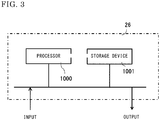
- the control device 26 is configured from a processor 1000 and a storage device 1001.
- the storage device includes a volatile storage device such as a random access memory, and a nonvolatile auxiliary storage device such as a flash memory.
- the storage device may include, as the auxiliary storage device, a hard disk instead of a flash memory.
- the processor 1000 executes a program inputted from the storage device 1001. In this case, the program is inputted from the auxiliary storage device via the volatile storage device to the processor 1000.
- the processor 1000 may output data of a calculation result or the like to the volatile storage device of the storage device 1001, or may store the data in the auxiliary storage device via the volatile storage device.
Landscapes
- Engineering & Computer Science (AREA)
- Chemical & Material Sciences (AREA)
- Combustion & Propulsion (AREA)
- Transportation (AREA)
- Mechanical Engineering (AREA)
- Power Engineering (AREA)
- Power Steering Mechanism (AREA)
- Steering Control In Accordance With Driving Conditions (AREA)
- Electric Propulsion And Braking For Vehicles (AREA)
- Steering-Linkage Mechanisms And Four-Wheel Steering (AREA)
Applications Claiming Priority (2)
| Application Number | Priority Date | Filing Date | Title |
|---|---|---|---|
| JP2017121905A JP6516792B2 (ja) | 2017-06-22 | 2017-06-22 | 電動パワーステアリング装置を搭載した車両 |
| PCT/JP2018/007451 WO2018235343A1 (ja) | 2017-06-22 | 2018-02-28 | 電動パワーステアリング装置およびそれを搭載した車両 |
Publications (3)
| Publication Number | Publication Date |
|---|---|
| EP3643583A1 true EP3643583A1 (de) | 2020-04-29 |
| EP3643583A4 EP3643583A4 (de) | 2020-08-05 |
| EP3643583B1 EP3643583B1 (de) | 2025-05-14 |
Family
ID=64735543
Family Applications (1)
| Application Number | Title | Priority Date | Filing Date |
|---|---|---|---|
| EP18821273.2A Active EP3643583B1 (de) | 2017-06-22 | 2018-02-28 | Elektrische servolenkvorrichtung und damit ausgestattetes fahrzeug |
Country Status (5)
| Country | Link |
|---|---|
| US (1) | US11584433B2 (de) |
| EP (1) | EP3643583B1 (de) |
| JP (1) | JP6516792B2 (de) |
| CN (1) | CN110753653A (de) |
| WO (1) | WO2018235343A1 (de) |
Cited By (2)
| Publication number | Priority date | Publication date | Assignee | Title |
|---|---|---|---|---|
| DE102024110822A1 (de) | 2024-04-17 | 2025-10-23 | Ford Global Technologies, Llc | Elektronisches Lenksystem für ein Fahrzeug und Verfahren zum Betrieb eines elektronischen Lenksystems für ein Fahrzeug |
| WO2026077782A1 (de) * | 2024-10-10 | 2026-04-16 | Robert Bosch Gmbh | Steuerung für ein fahrzeug und verfahren zum betreiben mindestens eines motorisierten aktors eines fahrzeugs |
Families Citing this family (11)
| Publication number | Priority date | Publication date | Assignee | Title |
|---|---|---|---|---|
| CN110682920B (zh) * | 2019-12-09 | 2020-04-21 | 吉利汽车研究院(宁波)有限公司 | 一种自动驾驶控制系统、控制方法及设备 |
| DE102020110661A1 (de) | 2020-04-20 | 2021-10-21 | Bayerische Motoren Werke Aktiengesellschaft | Verfahren zur Lenkkraftunterstützung eines Lenksystem eines Fahrzeuges |
| US11427086B2 (en) * | 2020-05-19 | 2022-08-30 | Kaney Aerospace, Inc. | System and method for electrical power conversion suited for driving an electric motor |
| JP2022030203A (ja) * | 2020-08-06 | 2022-02-18 | トヨタ自動車株式会社 | 転舵システム |
| EP3974287B1 (de) | 2020-09-24 | 2024-03-06 | Volvo Truck Corporation | Servolenksystem und verfahren zum betrieb eines servolenksystems |
| CN117615953A (zh) * | 2021-07-09 | 2024-02-27 | 日立安斯泰莫株式会社 | 电动动力转向装置、电动动力转向装置的控制方法以及转向控制装置 |
| CN114684254B (zh) * | 2022-04-29 | 2023-07-21 | 中汽创智科技有限公司 | 一种转向助力调节方法、装置、设备及存储介质 |
| CN114954646B (zh) * | 2022-06-16 | 2023-10-03 | 北京理工大学 | 一种车辆转向系统和转向方法 |
| JP7818481B2 (ja) * | 2022-07-08 | 2026-02-20 | 株式会社ジェイテクト | 操舵制御装置 |
| CN116142294A (zh) * | 2023-03-22 | 2023-05-23 | 重庆长安汽车股份有限公司 | 底盘域控制器、底盘系统架构及车辆 |
| KR20250175117A (ko) * | 2024-06-07 | 2025-12-16 | 현대모비스 주식회사 | 사륜 독립제어 자동차의 제어장치 및 그 방법 |
Family Cites Families (27)
| Publication number | Priority date | Publication date | Assignee | Title |
|---|---|---|---|---|
| JP2824838B2 (ja) * | 1987-12-10 | 1998-11-18 | スズキ株式会社 | 自動車の四輪操舵装置 |
| JPH06293276A (ja) * | 1993-04-06 | 1994-10-21 | Nippondenso Co Ltd | 車両の4輪操舵装置 |
| JP3572992B2 (ja) | 1999-04-21 | 2004-10-06 | 日立プラント建設株式会社 | 膜濾過装置の運転方法 |
| JP2001322557A (ja) * | 2000-05-17 | 2001-11-20 | Toyota Motor Corp | 車両の複数輪独立操舵装置 |
| JP2005112008A (ja) | 2003-10-02 | 2005-04-28 | Toyoda Mach Works Ltd | 車両の統合制御装置 |
| JP2005343256A (ja) * | 2004-06-01 | 2005-12-15 | Toyota Motor Corp | 車両の挙動制御装置 |
| FR2887839B1 (fr) * | 2005-07-04 | 2007-09-14 | Conception & Dev Michelin Sa | Systeme de direction d'un vehicule comportant un mode de fonctionnement degrade en cas de panne d'un actionneur de braquage de roue. |
| JP4539866B2 (ja) * | 2006-01-13 | 2010-09-08 | トヨタ自動車株式会社 | 転舵装置 |
| DE102010050799A1 (de) | 2010-11-09 | 2012-05-10 | Volkswagen Ag | Kraftfahrzeug mit elektrischer Hilfskraftlenkung |
| JP5435310B2 (ja) | 2011-09-08 | 2014-03-05 | 株式会社デンソー | 回転電機制御装置、および、これを用いた操舵制御システム |
| JP2013159165A (ja) * | 2012-02-02 | 2013-08-19 | Jtekt Corp | 電動パワーステアリング装置 |
| WO2013146976A1 (ja) | 2012-03-28 | 2013-10-03 | 株式会社クボタ | 膜分離装置の運転方法及び膜分離装置 |
| JP5841474B2 (ja) | 2012-03-28 | 2016-01-13 | 株式会社クボタ | 膜分離装置の運転方法及び膜分離装置 |
| JP5556845B2 (ja) * | 2012-04-26 | 2014-07-23 | 株式会社デンソー | 3相回転機の制御装置 |
| JP5653386B2 (ja) * | 2012-05-09 | 2015-01-14 | 三菱電機株式会社 | モータ制御装置およびそれを用いた電動パワーステアリング装置 |
| JP2014027726A (ja) * | 2012-07-25 | 2014-02-06 | Ntn Corp | 全輪モータ駆動車におけるモータ駆動装置 |
| ES2489341B1 (es) * | 2012-09-07 | 2015-03-17 | Microelectronica Maser, S.L. | Sistema de direccion asistida para vehiculos |
| US20140222292A1 (en) * | 2013-02-06 | 2014-08-07 | Steering Solutions Ip Holding Corporation | Vehicle electric power steering control system |
| DE102013207142B4 (de) * | 2013-04-19 | 2014-12-11 | Ford Global Technologies, Llc | Schneckengetriebe |
| US9102331B2 (en) * | 2013-09-20 | 2015-08-11 | GM Global Technology Operations LLC | Multi-functional electric module for a vehicle |
| JP6238284B2 (ja) * | 2013-10-22 | 2017-11-29 | 株式会社Ihiエアロスペース | インバータ装置 |
| JP5959591B2 (ja) * | 2014-10-09 | 2016-08-02 | 三菱電機株式会社 | 3相2重化モータ及び3相2重化モータの製造方法 |
| JP6979767B2 (ja) * | 2014-11-05 | 2021-12-15 | 日本電産株式会社 | モータ駆動装置および電動パワーステアリング装置 |
| DE102014224970A1 (de) * | 2014-12-05 | 2016-06-09 | Robert Bosch Gmbh | Lenkantrieb und Lenksystem für ein Fahrzeug |
| JP6421619B2 (ja) * | 2015-01-26 | 2018-11-14 | 株式会社デンソー | 回転電機 |
| EP3261248B1 (de) * | 2015-02-17 | 2025-11-26 | Mitsubishi Electric Corporation | Dreiphasiger permanentmagnetduplexmotor und elektrische servolenkvorrichtung |
| JP6275211B2 (ja) * | 2016-07-29 | 2018-02-07 | 三菱電機株式会社 | 電動パワーステアリング装置 |
-
2017
- 2017-06-22 JP JP2017121905A patent/JP6516792B2/ja active Active
-
2018
- 2018-02-28 EP EP18821273.2A patent/EP3643583B1/de active Active
- 2018-02-28 US US16/489,124 patent/US11584433B2/en active Active
- 2018-02-28 CN CN201880040086.7A patent/CN110753653A/zh active Pending
- 2018-02-28 WO PCT/JP2018/007451 patent/WO2018235343A1/ja not_active Ceased
Cited By (2)
| Publication number | Priority date | Publication date | Assignee | Title |
|---|---|---|---|---|
| DE102024110822A1 (de) | 2024-04-17 | 2025-10-23 | Ford Global Technologies, Llc | Elektronisches Lenksystem für ein Fahrzeug und Verfahren zum Betrieb eines elektronischen Lenksystems für ein Fahrzeug |
| WO2026077782A1 (de) * | 2024-10-10 | 2026-04-16 | Robert Bosch Gmbh | Steuerung für ein fahrzeug und verfahren zum betreiben mindestens eines motorisierten aktors eines fahrzeugs |
Also Published As
| Publication number | Publication date |
|---|---|
| JP2019006188A (ja) | 2019-01-17 |
| CN110753653A (zh) | 2020-02-04 |
| EP3643583A4 (de) | 2020-08-05 |
| US20200102007A1 (en) | 2020-04-02 |
| EP3643583B1 (de) | 2025-05-14 |
| JP6516792B2 (ja) | 2019-05-22 |
| WO2018235343A1 (ja) | 2018-12-27 |
| US11584433B2 (en) | 2023-02-21 |
Similar Documents
| Publication | Publication Date | Title |
|---|---|---|
| EP3643583A1 (de) | Elektrische servolenkvorrichtung und damit ausgestattetes fahrzeug | |
| EP3398832B1 (de) | Elektrische steer-by-wire-servolenkvorrichtung und steuerungsverfahren dafür | |
| US7222008B2 (en) | Vehicle steering control apparatus | |
| US20220250676A1 (en) | Motor drive system | |
| WO2021095644A1 (ja) | モータ駆動システム | |
| US11973453B2 (en) | Motor drive system | |
| US11472480B2 (en) | Electric power steering device | |
| EP3806319B1 (de) | Elektrische servolenkvorrichtung | |
| JP7101307B2 (ja) | ブレーキ制御装置 | |
| JP5754088B2 (ja) | 電動パワーステアリング装置 | |
| KR20220102948A (ko) | 조향 시스템 및 그 제어방법 | |
| KR102874164B1 (ko) | 조향 제어 장치 | |
| US20260103232A1 (en) | Steer-by-wire steering device, power supply system and vehicle including the same | |
| KR20210012251A (ko) | 전동 조향 장치 및 방법 | |
| EP4470874A2 (de) | Fahrzeugsteuerungsvorrichtung | |
| CN121291582A (zh) | 转向控制系统、转向控制设备及方法 | |
| JP2008273475A (ja) | 電動パワーステアリング装置 |
Legal Events
| Date | Code | Title | Description |
|---|---|---|---|
| STAA | Information on the status of an ep patent application or granted ep patent |
Free format text: STATUS: THE INTERNATIONAL PUBLICATION HAS BEEN MADE |
|
| PUAI | Public reference made under article 153(3) epc to a published international application that has entered the european phase |
Free format text: ORIGINAL CODE: 0009012 |
|
| STAA | Information on the status of an ep patent application or granted ep patent |
Free format text: STATUS: REQUEST FOR EXAMINATION WAS MADE |
|
| 17P | Request for examination filed |
Effective date: 20190916 |
|
| AK | Designated contracting states |
Kind code of ref document: A1 Designated state(s): AL AT BE BG CH CY CZ DE DK EE ES FI FR GB GR HR HU IE IS IT LI LT LU LV MC MK MT NL NO PL PT RO RS SE SI SK SM TR |
|
| AX | Request for extension of the european patent |
Extension state: BA ME |
|
| A4 | Supplementary search report drawn up and despatched |
Effective date: 20200702 |
|
| RIC1 | Information provided on ipc code assigned before grant |
Ipc: B62D 7/15 20060101ALI20200626BHEP Ipc: B62D 6/00 20060101ALI20200626BHEP Ipc: B62D 7/14 20060101ALI20200626BHEP Ipc: B62D 5/04 20060101AFI20200626BHEP Ipc: B62D 113/00 20060101ALI20200626BHEP |
|
| DAV | Request for validation of the european patent (deleted) | ||
| DAX | Request for extension of the european patent (deleted) | ||
| STAA | Information on the status of an ep patent application or granted ep patent |
Free format text: STATUS: EXAMINATION IS IN PROGRESS |
|
| 17Q | First examination report despatched |
Effective date: 20211220 |
|
| GRAP | Despatch of communication of intention to grant a patent |
Free format text: ORIGINAL CODE: EPIDOSNIGR1 |
|
| STAA | Information on the status of an ep patent application or granted ep patent |
Free format text: STATUS: GRANT OF PATENT IS INTENDED |
|
| INTG | Intention to grant announced |
Effective date: 20250109 |
|
| GRAS | Grant fee paid |
Free format text: ORIGINAL CODE: EPIDOSNIGR3 |
|
| GRAA | (expected) grant |
Free format text: ORIGINAL CODE: 0009210 |
|
| STAA | Information on the status of an ep patent application or granted ep patent |
Free format text: STATUS: THE PATENT HAS BEEN GRANTED |
|
| AK | Designated contracting states |
Kind code of ref document: B1 Designated state(s): AL AT BE BG CH CY CZ DE DK EE ES FI FR GB GR HR HU IE IS IT LI LT LU LV MC MK MT NL NO PL PT RO RS SE SI SK SM TR |
|
| REG | Reference to a national code |
Ref country code: GB Ref legal event code: FG4D |
|
| REG | Reference to a national code |
Ref country code: CH Ref legal event code: EP |
|
| REG | Reference to a national code |
Ref country code: DE Ref legal event code: R096 Ref document number: 602018081964 Country of ref document: DE |
|
| REG | Reference to a national code |
Ref country code: IE Ref legal event code: FG4D |
|
| REG | Reference to a national code |
Ref country code: NL Ref legal event code: MP Effective date: 20250514 |
|
| PG25 | Lapsed in a contracting state [announced via postgrant information from national office to epo] |
Ref country code: PT Free format text: LAPSE BECAUSE OF FAILURE TO SUBMIT A TRANSLATION OF THE DESCRIPTION OR TO PAY THE FEE WITHIN THE PRESCRIBED TIME-LIMIT Effective date: 20250915 Ref country code: FI Free format text: LAPSE BECAUSE OF FAILURE TO SUBMIT A TRANSLATION OF THE DESCRIPTION OR TO PAY THE FEE WITHIN THE PRESCRIBED TIME-LIMIT Effective date: 20250514 Ref country code: ES Free format text: LAPSE BECAUSE OF FAILURE TO SUBMIT A TRANSLATION OF THE DESCRIPTION OR TO PAY THE FEE WITHIN THE PRESCRIBED TIME-LIMIT Effective date: 20250514 |
|
| REG | Reference to a national code |
Ref country code: LT Ref legal event code: MG9D |
|
| PG25 | Lapsed in a contracting state [announced via postgrant information from national office to epo] |
Ref country code: NO Free format text: LAPSE BECAUSE OF FAILURE TO SUBMIT A TRANSLATION OF THE DESCRIPTION OR TO PAY THE FEE WITHIN THE PRESCRIBED TIME-LIMIT Effective date: 20250814 Ref country code: GR Free format text: LAPSE BECAUSE OF FAILURE TO SUBMIT A TRANSLATION OF THE DESCRIPTION OR TO PAY THE FEE WITHIN THE PRESCRIBED TIME-LIMIT Effective date: 20250815 |
|
| PG25 | Lapsed in a contracting state [announced via postgrant information from national office to epo] |
Ref country code: NL Free format text: LAPSE BECAUSE OF FAILURE TO SUBMIT A TRANSLATION OF THE DESCRIPTION OR TO PAY THE FEE WITHIN THE PRESCRIBED TIME-LIMIT Effective date: 20250514 Ref country code: PL Free format text: LAPSE BECAUSE OF FAILURE TO SUBMIT A TRANSLATION OF THE DESCRIPTION OR TO PAY THE FEE WITHIN THE PRESCRIBED TIME-LIMIT Effective date: 20250514 |
|
| REG | Reference to a national code |
Ref country code: AT Ref legal event code: MK05 Ref document number: 1794584 Country of ref document: AT Kind code of ref document: T Effective date: 20250514 |
|
| PG25 | Lapsed in a contracting state [announced via postgrant information from national office to epo] |
Ref country code: BG Free format text: LAPSE BECAUSE OF FAILURE TO SUBMIT A TRANSLATION OF THE DESCRIPTION OR TO PAY THE FEE WITHIN THE PRESCRIBED TIME-LIMIT Effective date: 20250514 |
|
| PG25 | Lapsed in a contracting state [announced via postgrant information from national office to epo] |
Ref country code: HR Free format text: LAPSE BECAUSE OF FAILURE TO SUBMIT A TRANSLATION OF THE DESCRIPTION OR TO PAY THE FEE WITHIN THE PRESCRIBED TIME-LIMIT Effective date: 20250514 |
|
| PG25 | Lapsed in a contracting state [announced via postgrant information from national office to epo] |
Ref country code: AT Free format text: LAPSE BECAUSE OF FAILURE TO SUBMIT A TRANSLATION OF THE DESCRIPTION OR TO PAY THE FEE WITHIN THE PRESCRIBED TIME-LIMIT Effective date: 20250514 |
|
| PG25 | Lapsed in a contracting state [announced via postgrant information from national office to epo] |
Ref country code: RS Free format text: LAPSE BECAUSE OF FAILURE TO SUBMIT A TRANSLATION OF THE DESCRIPTION OR TO PAY THE FEE WITHIN THE PRESCRIBED TIME-LIMIT Effective date: 20250814 |
|
| PG25 | Lapsed in a contracting state [announced via postgrant information from national office to epo] |
Ref country code: IS Free format text: LAPSE BECAUSE OF FAILURE TO SUBMIT A TRANSLATION OF THE DESCRIPTION OR TO PAY THE FEE WITHIN THE PRESCRIBED TIME-LIMIT Effective date: 20250914 |
|
| PG25 | Lapsed in a contracting state [announced via postgrant information from national office to epo] |
Ref country code: LV Free format text: LAPSE BECAUSE OF FAILURE TO SUBMIT A TRANSLATION OF THE DESCRIPTION OR TO PAY THE FEE WITHIN THE PRESCRIBED TIME-LIMIT Effective date: 20250514 |
|
| PG25 | Lapsed in a contracting state [announced via postgrant information from national office to epo] |
Ref country code: DK Free format text: LAPSE BECAUSE OF FAILURE TO SUBMIT A TRANSLATION OF THE DESCRIPTION OR TO PAY THE FEE WITHIN THE PRESCRIBED TIME-LIMIT Effective date: 20250514 Ref country code: SM Free format text: LAPSE BECAUSE OF FAILURE TO SUBMIT A TRANSLATION OF THE DESCRIPTION OR TO PAY THE FEE WITHIN THE PRESCRIBED TIME-LIMIT Effective date: 20250514 |
|
| PGFP | Annual fee paid to national office [announced via postgrant information from national office to epo] |
Ref country code: FR Payment date: 20251231 Year of fee payment: 9 |
|
| PG25 | Lapsed in a contracting state [announced via postgrant information from national office to epo] |
Ref country code: CZ Free format text: LAPSE BECAUSE OF FAILURE TO SUBMIT A TRANSLATION OF THE DESCRIPTION OR TO PAY THE FEE WITHIN THE PRESCRIBED TIME-LIMIT Effective date: 20250514 |
|
| PG25 | Lapsed in a contracting state [announced via postgrant information from national office to epo] |
Ref country code: EE Free format text: LAPSE BECAUSE OF FAILURE TO SUBMIT A TRANSLATION OF THE DESCRIPTION OR TO PAY THE FEE WITHIN THE PRESCRIBED TIME-LIMIT Effective date: 20250514 |
|
| PG25 | Lapsed in a contracting state [announced via postgrant information from national office to epo] |
Ref country code: RO Free format text: LAPSE BECAUSE OF FAILURE TO SUBMIT A TRANSLATION OF THE DESCRIPTION OR TO PAY THE FEE WITHIN THE PRESCRIBED TIME-LIMIT Effective date: 20250514 Ref country code: SK Free format text: LAPSE BECAUSE OF FAILURE TO SUBMIT A TRANSLATION OF THE DESCRIPTION OR TO PAY THE FEE WITHIN THE PRESCRIBED TIME-LIMIT Effective date: 20250514 |
|
| PG25 | Lapsed in a contracting state [announced via postgrant information from national office to epo] |
Ref country code: IT Free format text: LAPSE BECAUSE OF FAILURE TO SUBMIT A TRANSLATION OF THE DESCRIPTION OR TO PAY THE FEE WITHIN THE PRESCRIBED TIME-LIMIT Effective date: 20250514 |
|
| REG | Reference to a national code |
Ref country code: DE Ref legal event code: R097 Ref document number: 602018081964 Country of ref document: DE |
|
| PLBE | No opposition filed within time limit |
Free format text: ORIGINAL CODE: 0009261 |
|
| STAA | Information on the status of an ep patent application or granted ep patent |
Free format text: STATUS: NO OPPOSITION FILED WITHIN TIME LIMIT |
|
| REG | Reference to a national code |
Ref country code: CH Ref legal event code: L10 Free format text: ST27 STATUS EVENT CODE: U-0-0-L10-L00 (AS PROVIDED BY THE NATIONAL OFFICE) Effective date: 20260325 |
|
| PGFP | Annual fee paid to national office [announced via postgrant information from national office to epo] |
Ref country code: DE Payment date: 20260102 Year of fee payment: 9 |
|
| 26N | No opposition filed |
Effective date: 20260217 |