EP3643839A2 - Amortisseur de sons émis sous l'eau et procédé de manipulation d'un amortisseur de sons émis sous l'eau - Google Patents
Amortisseur de sons émis sous l'eau et procédé de manipulation d'un amortisseur de sons émis sous l'eau Download PDFInfo
- Publication number
- EP3643839A2 EP3643839A2 EP19208637.9A EP19208637A EP3643839A2 EP 3643839 A2 EP3643839 A2 EP 3643839A2 EP 19208637 A EP19208637 A EP 19208637A EP 3643839 A2 EP3643839 A2 EP 3643839A2
- Authority
- EP
- European Patent Office
- Prior art keywords
- hydraulic
- silencer
- support structure
- elements
- holding elements
- Prior art date
- Legal status (The legal status is an assumption and is not a legal conclusion. Google has not performed a legal analysis and makes no representation as to the accuracy of the status listed.)
- Granted
Links
Images




Classifications
-
- E—FIXED CONSTRUCTIONS
- E02—HYDRAULIC ENGINEERING; FOUNDATIONS; SOIL SHIFTING
- E02D—FOUNDATIONS; EXCAVATIONS; EMBANKMENTS; UNDERGROUND OR UNDERWATER STRUCTURES
- E02D13/00—Accessories for placing or removing piles or bulkheads, e.g. noise attenuating chambers
- E02D13/005—Sound absorbing accessories in piling
-
- E—FIXED CONSTRUCTIONS
- E02—HYDRAULIC ENGINEERING; FOUNDATIONS; SOIL SHIFTING
- E02D—FOUNDATIONS; EXCAVATIONS; EMBANKMENTS; UNDERGROUND OR UNDERWATER STRUCTURES
- E02D7/00—Methods or apparatus for placing sheet pile bulkheads, piles, mouldpipes, or other moulds
- E02D7/02—Placing by driving
-
- E—FIXED CONSTRUCTIONS
- E02—HYDRAULIC ENGINEERING; FOUNDATIONS; SOIL SHIFTING
- E02B—HYDRAULIC ENGINEERING
- E02B17/00—Artificial islands mounted on piles or like supports, e.g. platforms on raisable legs or offshore constructions; Construction methods therefor
-
- E—FIXED CONSTRUCTIONS
- E02—HYDRAULIC ENGINEERING; FOUNDATIONS; SOIL SHIFTING
- E02D—FOUNDATIONS; EXCAVATIONS; EMBANKMENTS; UNDERGROUND OR UNDERWATER STRUCTURES
- E02D27/00—Foundations as substructures
- E02D27/32—Foundations for special purposes
- E02D27/52—Submerged foundations, i.e. submerged in open water
- E02D27/525—Submerged foundations, i.e. submerged in open water using elements penetrating the underwater ground
Definitions
- the invention relates to a hydraulic silencer for reducing water noise, in particular in the area of a construction site for an object to be introduced into an underwater floor, the hydraulic silencer having an upper end and a lower end opposite the upper end, with side flanks extending between the upper end and the lower end are, wherein the hydraulic silencer is divisible along the side flanks and movable between a closed position and an open position, wherein the hydraulic silencer has at least one support structure, wherein a lower end of the at least one support structure is movably fixed relative to the at least one floor element.
- the invention further relates to a method for handling a hydraulic muffler and / or for positioning a hydraulic muffler in the area of a construction site for an object to be inserted into an underwater floor.
- Underwater soil is understood to mean the solid soil body below a water column.
- An underwater floor in the sense of the present invention is a sea floor or the bottom of a harbor basin or an inland water such as a lake or a river.
- the objects that are often brought into the underwater floor during underwater work are foundation bodies such as piles or structural parts such as wall elements that are introduced into the underwater floor by drilling or ramming.
- Other sound-emitting devices, such as a drill pipe are also to be understood as an object to be introduced into the underwater bottom.
- Marine mammals such as porpoises and seals, can perceive long-distance underwater noise, such as occurs in the underwater work described.
- Underwater noise primarily affects those animals that use their hearing in addition to communication for orientation and foraging. In these animals, permanent hearing damage can result in death.
- envelopes made of elastic material can also be used as noise reduction elements.
- a large number of sound reduction elements are arranged on a support structure. This is, for example, a network that can be flexibly stretched around the sound source in the water. The nets are held on the underwater floor with weights.
- the entirety of the noise reduction elements with the support structure is called a hydraulic silencer.
- a hydraulic muffler has an additional damping effect and can be tailored precisely to the expected sound spectrum.
- a hydraulic silencer is less susceptible to ocean currents and optimally effective in the entire relevant frequency range.
- a continuous compressed air supply as with a bubble curtain is not required with a hydraulic silencer.
- a hydraulic silencer known. This consists of a plurality of mutually spaced damping elements for reducing the hydro sound, which are distributed on a Support structure, for example on a network, are arranged.
- the support structure is arranged around a sound source at the place of use.
- a sound source is, for example, a pile, which is placed in the underwater floor, which can be done by ramming or drilling.
- the generic DE 10 2004 043 128 A1 relates to a pile guide device for guiding a pile to be rammed into a body of water, which is enclosed by an inner and an outer textile curtain, so that the bubbles emerging from a nozzle arrangement rise between the two textile curtains.
- the nozzle arrangement consists of two rigid legs which are connected to two joints, so that the nozzle arrangement can be opened in order to insert the pile laterally into the nozzle arrangement. Then the movable legs are closed so that the pile is enclosed and fixed in its correct position.
- the DE 10 2012 206 907 A1 shows a device for reducing the propagation of sound, vibrations and pressure surges in a liquid when introducing an object into a substrate with several gas-filled damping bodies and a support on which the damping bodies are arranged in a suitable relative position to each other.
- the carrier has a frame with vertical and horizontal linkage elements arranged perpendicular to one another, which is movable by means of joints between a closed position and an open position.
- the frame areas constructed from horizontal linkage elements can be coupled to one another via ropes in order to enable particularly space-saving storage or transport of the device when it is not in use.
- the publication WO 2013/102459 A2 describes a method and a device for handling a hydraulic muffler in the area of an offshore construction site, in particular in the case of a pile to be inserted into the underwater floor.
- the disclosed device comprises a holding device on which a first end of the hydraulic muffler is held, and a second end of the hydraulic muffler which is remote from the first end of the hydraulic muffler and which can be positioned relative to the holding device, in particular at a distance from the holding device.
- the DE 10 2006 008 095 A1 shell-shaped segments made of a sound-absorbing material, which are connected by hinges and which together form a rigid soundproof sleeve.
- the GB 2509208 A refers to such a rigid soundproof cover.
- the invention has for its object to provide a way in the field of underwater work such as drilling or ramming an object in the underwater floor, both the handling of a hydro muffler to reduce the generation or spread of hydro noise and the handling of the object, so that to simplify Workflows can be carried out quickly, safely and thus ultimately inexpensively.
- the hydraulic silencer has sound-reducing elements fastened to and spaced from one another on the at least one support structure, the support structure being formed from a number of a plurality of parallel vertical ropes and / or mesh strips and / or mesh tubes and / or mesh tubes and / or from a mesh equipped with the sound-proofing elements. So both the handling of the hydraulic muffler and the handling of the object is easier than with known hydraulic mufflers.
- the side flanks are movable relative to one another between two end positions, an open position and a closed position.
- a body that extends deep into the water for example a vertically held pile
- the side flanks are positioned at a short distance from one another, touching one another and / or overlapping one another.
- the side flanks are at a large distance, which is larger than the cross section of the object.
- the mutually movable side flanks belong, for example, to a single support structure and / or to separate support structures which, for example, consist of a number of several parallel vertical ropes and / or mesh strips equipped with sound reduction elements and / or net tubes are formed, which are held at the lower end on a base element and float freely at the upper end.
- a network is preferably used as the support structure for the noise reduction elements.
- a grid in particular a narrow cage, a wire mat, a perforated metal sheet or a rigid wire mesh.
- Several of the rigid support structures designed as sheet-like bodies can be moved relative to one another, preferably in a translatory and / or rotary manner, between the rest position and the working position.
- the support structures are preferably arranged in staggered planes or in concentric rings to one another.
- Carrier structures in the form of cages can also be telescopic or arranged one on top of the other and / or next to one another, for example stackable.
- the upper end and the lower end of the at least one support structure prefferably be translationally movable relative to one another in a vertical direction and / or in a horizontal direction approximately perpendicular to the vertical direction. This makes it possible for the support structure to be moved together for a movement of the hydraulic muffler between the open position and the closed position or for a movement of the hydraulic muffler and to stow it securely in a transport housing.
- the hydraulic silencer comprises at least one floor element, which is assigned to the lower end of the at least one support structure, the lower end being movable relative to the at least one floor element or being fixed to the at least one floor element.
- the at least one base element is translationally movable relative to the holding elements in a vertical direction, so that the at least one support structure can be spread out or gathered together by means of the vertical movement of the at least one base element. This is possible by attaching the lower end of the support structure to the floor element.
- the vertical mobility of the at least one floor element is advantageous, since the at least one floor element can be lifted from the underwater floor when the hydraulic muffler is displaced, which facilitates the handling of the hydraulic muffler.
- the floor element has an underwater winch or deflection roller for spreading out the support structure.
- the at least one floor element also serves as a mass body, which acts against the buoyancy of the sound reduction elements.
- the at least one floor element is movable in the vertical direction between a rest position and a working position, wherein it rests on the underwater bottom in the working position and rests on at least one of the holding elements in the rest position or is locked with it.
- the holding elements are connected to the at least one floor element by the support structures and / or by means of ropes.
- the ropes can also be designed as rods.
- the support structures are preferably arranged to be movable on the ropes or rods.
- the at least one base element and the holding elements can be designed as containers with closed walls. However, it has proven advantageous for a flow through the hydraulic muffler that the at least one base element and the holding elements are designed as cages with open-flow walls.
- the hydraulic silencer preferably has a plurality of base elements, at least one base element being movable parallel to a horizontal plane together with one of the holding elements.
- the hydraulic silencer comprises a guide device for a pile, such as a so-called gripper, with at least one movable arm for gripping the pile, with the at least one movable arm of the guide device a holding element is attached.
- a holding element is attached to the guide device.
- at least one holding element it is possible for at least one holding element to be fixed to the hull of a ship or to be connected to a lifting device fastened to the ship, for example a crane or swivel arm.
- a ship or installer ship in the sense of the invention is a floating device and / or placed on the underwater bed or on the land side at the water's edge.
- the hydraulic silencer can also be designed completely independently of an installer ship or a guide device.
- the hydraulic silencer, at least one holding element and / or base element to be connected to the object by means of at least one movable arm.
- the guide device In the closed position, the guide device usually encloses the stake to about two thirds, in any case more than half of its circumference.
- the hydraulic silencer preferably completely encloses the pile.
- the hydraulic silencer preferably comprises several elements in one plane, for example holding elements, which are connected to one another by means of bearings.
- a hydraulic silencer consists of four holding elements which have the shape of a quarter circle and are connected to one another by three rotary joints.
- the bearings for connecting the elements to one another can be designed as rotary bearings or sliding bearings for a rotational or translational movement. It is possible that the elements of a hydraulic silencer are connected by means of different types of bearings. For example, a hydraulic silencer with four holding elements can be provided, which has a sliding mechanism as a bearing between the two middle holding elements and in which the outer holding elements are connected to the middle holding elements by means of rotary joints.
- the arrangement of the bearings or the shape and extension of the elements can be symmetrical or asymmetrical.
- a method in which, in order to move the object through the level of the hydraulic muffler, the muffler is brought into an open position by moving the side flanks away from one another and for inserting the object into the underwater bottom of the hydraulic muffler is moved into a closed position by moving the Side edges are moved towards each other.
- an object is first moved into the insertion position by an insertion device. Subsequently a guide device and at least two holding elements of the hydraulic muffler are moved from an open position into a closed position, the object being held immovably by the guide device and enclosed by the holding elements. The hydraulic muffler is then spread out, a lower end of the hydraulic muffler being moved down to the underwater floor or to a bottom element resting on the underwater floor. The object is then introduced into the underwater bottom using the insertion device. The hydraulic silencer is then at least partially contracted, the lower end being moved away from the underwater floor. The guide device and the at least two holding elements are then released to move the object from the closed position into the open position. This simplifies the handling of the object and the hydraulic silencer.
- the distance of the side flanks extending between an upper end and a lower end of the support structure is reduced in the case of a hydraulic noise suppressor with a single support structure.
- the distance between two side flanks of different support structures is reduced in order to achieve the closed position.
- the guide device and the holding device can in principle be moved independently of one another between the open position and the closed position. It has proven to be particularly practical that the guide device and the at least two holding elements are moved together, in particular simultaneously between the open position and the closed position.
- the guide device and the at least two holding elements are not moved synchronously with one another or independently of one another.
- the movement of the individual elements, for example holding elements of a hydraulic silencer, can also take place synchronously or independently of one another.
- the at least one support structure is completely pulled together before each movement of the at least two holding elements, in particular that the at least one base element is brought into the rest position.
- a hydraulic sound damper 4 is provided, of which some exemplary embodiments are described in more detail below. In the exemplary embodiments of the hydraulic silencer 4 shown in the figures, the method according to the invention is also explained.
- the method is used to handle the hydraulic silencer 4 in the area of an offshore construction site, in particular in the case of an object 1 to be inserted into the underwater floor 2.
- the hydraulic silencer 4 can develop its effect particularly well if the sound source, here the object 1, is largely enclosed by the hydraulic silencer 4.
- the hydraulic noise suppressor 4 which consists, for example, of a network as a flexible support structure 5 with sound reduction elements 10 attached to it, it is provided that the hydraulic noise suppressor 4 is arranged in the direction of FIG Figures 4 to 9 shown side flanks 6 is divided.
- the side flanks 6 extend between an upper end 7 and a lower end 8 of the hydraulic silencer 4 and are each embodied by at least one cable 13.
- the Figures 1 to 3 show an object 1 introduced into the underwater bottom 2 at the end of the introduction.
- An insertion tool 9 is still placed on the object 1.
- the hydraulic silencer 4 shown in a schematic section comprises the already mentioned flexible support structure 5, to which a multiplicity of noise reduction elements 10 are attached. Furthermore, the hydraulic silencer 4 has at least two rigid holding elements 11, which are connected to the upper end 7 of the at least one support structure 5, and one also called a gripper Guide device 15 for the erected object 1. By means of the guide device 15, a horizontal movement of the object 1 is suppressed when it is brought down.
- the holding elements 11 are arranged on the guide device 15. As shown, the holding elements 11 are fixed directly to the guide device 15 or attached to the guide device 15 by means of ropes. The latter enables the holding elements 11 to be lowered onto the water surface, which is preferably done by means of winches arranged on the holding elements 11. The at least two holding elements 11 are moved together with the arms of the guide device 15 in a horizontal plane for receiving an object 1.
- the hydraulic silencer 4 comprises at least one base element 12.
- the at least one base element 12 is movable relative to the holding elements 11.
- the cables 13 which extend between the at least one bottom element 12 and the holding elements 11, the at least one bottom element 12 can be moved between the underwater bottom 2 and the holding elements 11.
- winches 14 are arranged on the at least one floor element 12 and / or on the holding elements 11.
- the ropes 13 can also serve to guide the at least one support structure 5. It is also possible for a hose for generating a bubble curtain and / or for generating or controlling buoyancy to be held in the base element 12 in the hydraulic silencer 4 according to the invention.
- the bubble curtain and / or the buoyancy body and / or the noise reduction elements have a common compressed air supply, which comprises, for example, a common line and / or a common compressor.
- the lower end 8 of the at least one support structure 5 is connected to the at least one floor element 12 and is spread out when the at least one floor element 12 is lowered.
- the lower end 8 of the at least one support structure 5 is movable relative to the at least one floor element 12, it being possible for the lower end 8 to be pulled towards the at least one floor element 12 via further ropes and winches, not shown here.
- the at least one support structure 5 is brought in solely by the buoyancy of the sound reduction elements 10 attached to the at least one support structure 5.
- Figure 1 shows the at least one floor element 12 in a working position.
- the at least one bottom element 12 is deposited on the underwater bottom 2.
- the Holding elements 11 extends a hydraulic noise reducing curtain.
- the curtain is, for example, a support structure 5 with sound reduction elements 10 attached to it, a bubble curtain with freely rising air bubbles or a combination of different devices for reducing water noise.
- the curtain for the water surrounding the hydraulic muffler 4 can be flowed through, but includes a limited volume of water containing the sound source and thus separates it from the environment.
- Figure 2 shows the at least one floor element 12 in an intermediate position.
- the at least one bottom element 12 is lifted off the underwater bottom 2.
- the distance to the underwater floor 2 is sufficiently large so that the hydraulic silencer 4 can be moved away from an object 1 introduced into the underwater floor 2 and to a new insertion location.
- Figure 3 shows the at least one floor element 12 in a rest position.
- the at least one floor element 12 bears against the holding elements 11.
- the holding elements 11 are locked with the at least one base element 12 in the rest position.
- the rest position is particularly well suited for transporting the hydraulic silencer 4, since the at least one support structure 5 is securely stowed in a transport housing 16.
- the transport housing 16 is formed by the base element 12 and the holding element 11.
- the hydraulic silencer 4 is preferably opened in the rest position.
- the Figures 4 to 9 show in schematic views three different methods for handling a hydraulic silencer 4. Shown are the holding elements 11, one or more base elements 12 and the at least one support structure 5 and the cables 13 tensioned between the holding element 11 and the base element 12 when a flexible support structure 5 is used only a section of the at least one support structure 5 is shown.
- the at least one support structure 5 can be spatially extended in depth as a single support structure 5, for example enclosing the object 1 (not shown).
- the hydraulic silencer 4 can also comprise a plurality of support structures 5, which are designed as a disk-like wall, for example positioned in front of a port entrance.
- a plurality of ropes 13 are assigned to each holding element 11, at least one rope 13 being positioned on each side flank 6.
- the Figures 4 and 5 show a hydraulic silencer 4, comprising two holding elements 11 and two base elements 12.
- the hydraulic silencer 4 can be divided along the side flanks 6.
- the opening and closing movement takes place while the hydraulic silencer 4 is in an intermediate position.
- the holding elements 11 and base elements 12 are pivoted or shifted in pairs, so that the distance between the side flanks 6 is increased.
- the movement 17 of the holding elements 11 and base elements 12 and of the side flanks 6 is indicated by a double arrow.
- this movement 17 is reversed.
- the closed position of the hydraulic silencer 4 is shown. The distance between the side flanks 6 is minimized.
- the side flanks 6 can also be positioned overlapping in the closed position.
- Figure 5 shows the open position of the hydraulic muffler 4. In the open position, the distance between the side flanks 6 is significantly larger than in the closed position.
- the hydraulic silencer 4 shown here can consist of a support structure 5 which is connected to all holding elements 11 and floor elements 12.
- the hydraulic silencer 4 shown here can also consist of two independent support structures 5, each support structure being connected to a holding element 11 and a base element 12. For the movement 17 of the bottom elements 12, they are moved from the underwater bottom 2 into the intermediate position shown or into a rest position.
- the Figures 6 and 7 show a hydraulic silencer 4, comprising two holding elements 11 and a base element 12.
- the hydraulic silencer 4 can be divided along the side flanks 6.
- the holding elements 11 are pivoted or shifted, so that a wedge-shaped opening is formed between the side flanks 6.
- the support structure 5 is connected to the floor element 12.
- FIGS 8 and 9 show a variant of the in the Figures 6 and 7 described method, starting from the closed position of the Figure 6 first the support structure 5 is pulled up to the holding elements 11 and then the holding elements 11 according to the Figure 7 be moved until the open position is reached.
- the Figures 10 to 24 show, in schematic top views, the movement 17 of at least the holding elements 11.
- the holding elements 11 movable relative to one another, if appropriate the floor elements 12 are, for example, as in the Figures 10, 11 , 13 to 16 and 20 to 24 shown, connected by means of at least one bearing 18.
- the at least one bearing 18 can be designed as a joint which enables a rotational movement 17 between the holding elements 11.
- Such an articulated bearing 18 is in the Figures 10, 13 , 20 to 22 and 23 shown.
- the bearing 18 can also be a guide which enables a rotational or translatory movement 17 between the holding elements 11.
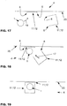
- Such a guide-like bearing 18 is in the Figures 11 , 17 to 19 and 24.
- the holding elements 11, which are movable relative to one another, optionally also the base elements 12, can also, as in FIGS Figures 12 and 17 to 19 shown to be carried out independently of one another.
- the Figures 14 to 22 show the method for positioning the hydraulic muffler 4 and the object 1 at an offshore construction site for introducing a pile into the underwater bottom 2.
- FIGs 14 to 16 show a first variant of the method.
- a multi-part hydraulic silencer 4 is provided, in which each part comprises a holding element 11 and a base element 12, as well as a support structure 5, not shown, arranged in between.
- the two parts of the hydraulic silencer 4 are at a distance in the open position ( Figure 14 ). This distance, in particular between the side flanks 6, enables simple, problem-free and safe positioning 19 of the object 1, which is a pile here.
- the two parts of the hydraulic muffler 4 are attached to a ship 20. As soon as the object 1 is positioned at its point of introduction, one of the parts of the hydraulic silencer 4 is moved 17 towards the other part ( Figure 15 ) until the closed position is reached ( Figure 16 ).
- the movement 17 of one part preferably takes place along a guide attached to the ship 20. If the support structure 5 has not yet been expanded, the bottom element 12 and the lower end 8 of the support structure 5 are now lowered onto the underwater floor 2. Then the sound-emitting work can be started. After the object 1 has been introduced into the underwater bottom 2, the bottom element 12 is moved into the intermediate position or the rest position and the parts of the hydraulic silencer 4 are moved away from one another again until the open position is reached. The ship 20 can then be moved to a new insertion position and the process begins again.
- FIGs 17 to 19 show a second variant of the method.
- an at least two-part hydraulic muffler 4 is provided, in which each part has a holding element 11 and a base element 12, and one arranged in between Carrier structure 5 comprises.
- Part of the hydraulic silencer 4 is fastened to a ship 20, while the other part is movable relative to the ship 20 in a floating manner.
- the open position ( Figure 17 ) of the hydraulic muffler 4 the object 1 is positioned at its insertion location 19.
- the floating part of the hydraulic muffler 4 is moved 17 to the part attached to the ship 20 ( Figure 18 ).
- the hydraulic silencer 4 remains in the closed position ( Figure 19 ).
- FIGS. 20 to 22 show a third variant of the method.
- a hydraulic silencer 4 is provided, in which the two holding elements 11 are pivotally connected to one another.
- This hydraulic silencer 4 preferably also has two floor elements 12, with each holding element 11 being assigned a floor element 12.
- the floor elements 12 are also pivotally connected to one another.
- the hydraulic silencer 4 can also comprise a plurality of hinge axes, for example consist of four pairs, each with a holding element 11 and a base element 12, the four pairs being rotatably connected to one another via three hinge axes. Each pair covers a quarter circle, so that the closed hydraulic silencer 4 encompasses the object 1.
- the hydraulic silencer 4 can be fastened to a ship 20 and / or to a lifting device and / or to a guide device 15, held by a crane of the ship 20 or detached from the ship 20, for example by being able to move independently.
- the object 1 is positioned 19 ( Figure 20 ).
- the hydraulic silencer 4 is then closed by at least one pivoting movement 17 of at least one pair of holding element 11 and base element 12 ( Figure 21 ) until the closed position ( Figure 22 ) is reached and thus the hydraulic silencer 4 encloses the object 1.
- the Figures 23 and 24 show the method for handling the hydraulic muffler 4 and an object 1 at a construction site between two headlands 21.
- the headlands 21 can be two moles in a port area or form a bay on the coast. In the area of inland waters, the headlands are 21 opposite banks of a river or two bank sections of a lake.
- the support structure 5 is rigid here and consists, for example, of a grid. The use of a rigid support structure 5 has proven to be advantageous in particular in the case of a hydraulic silencer 4 which remains in the same place for a long time, therefore not or only rarely.
- As an alternative to a grid it is also possible to use, in particular, narrow cages, wire mats, plastic mats, perforated metal sheets or rigid and / or flexible wire and / or plastic braids.
- FIG 23 shows a fourth variant of the method according to the invention.
- a multi-part hydraulic silencer 4 is provided, in which each part comprises a support structure 5, at least two holding elements 11 and at least two floor elements 12.
- the holding elements 11 and the bottom elements 12 of each part are pivotally connected to one another.
- the mutually assigned pairs of holding element 11 and base element 12 are rotated together around a bearing 18.
- the Figure 24 shows a fifth variant of the method according to the invention.
- a multi-part hydraulic silencer 4 is provided, in which each part comprises a support structure 5, a holding element 11 and a base element 12.
- Two parts of the hydraulic muffler 4 are positioned like a wall between the headlands 21. There is a gap between these two parts. The gap can be closed by the at least one further part. Between the open position and the closed position of the hydraulic silencer 4, the at least one further part is moved 17, for example in a translatory manner, relative to the other two parts.
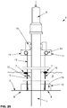
- FIG 25 shows a hydraulic silencer 4, which in the Figures 1 to 3 Hydraulic silencer 4 shown is similar.
- the holding elements 11 and the base elements 12 are connected via cables 13, the base elements 12 being movable relative to the holding elements 11 by means of winches 14 arranged on the holding elements 11 or on the guide device 15.
- the base element 12 is designed as a transport housing 16, which receives the support structure 5 with the sound reduction elements 10 outside the water 3.
- the transport housing 16 is preferably a lattice cage open at the top. If the floor element 12 is let down into the water 3, the sound reduction elements 10 float.
- the support structure 5 and noise reduction elements 10 are pulled down to the underwater bottom 2 and thus spread over the entire water column.
- the upper end 7 of the support structure 5 floats freely on the water surface.
- the holding elements 11 are fixed to the guide device 15 by means of ropes or shackles. After positioning the object 1, the hydraulic silencer 4 is closed.
- the bottom element 12 After closing, the bottom element 12 is lowered.
- the opening and closing of the hydraulic noise damper 4 is preferably carried out above the water level, the sound-reducing elements 10 receiving no buoyancy.
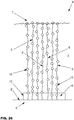
- Figure 26 shows a special embodiment of a hydraulic silencer 4, in which a bottom element 12 has been placed on the underwater bottom 2.
- Numerous support structures 5 with sound-reducing elements 10, which are independent of one another, are arranged on this floor element 12.
- the lower ends 8 of the support structures 5 are connected to the base element 12, which suppresses further ascent of the support structures 5 and noise reduction elements 10.
- the support structures 5 consist of individual ropes or narrow mesh strips or are individual mesh tubes, in the interior of which the sound reduction elements 10 are arranged.
- Each of the support structures 5 has a side flank 6 to the support structures 5 adjacent to it.
- This embodiment variant of the hydraulic silencer 4 has a multiple division and can therefore be penetrated simply because the upper ends 7 of the support structures 5 are free and avoid a passing object 1.
Landscapes
- Engineering & Computer Science (AREA)
- General Engineering & Computer Science (AREA)
- General Life Sciences & Earth Sciences (AREA)
- Mining & Mineral Resources (AREA)
- Paleontology (AREA)
- Civil Engineering (AREA)
- Life Sciences & Earth Sciences (AREA)
- Structural Engineering (AREA)
- Earth Drilling (AREA)
- Revetment (AREA)
- Pit Excavations, Shoring, Fill Or Stabilisation Of Slopes (AREA)
- Excavating Of Shafts Or Tunnels (AREA)
- Placing Or Removing Of Piles Or Sheet Piles, Or Accessories Thereof (AREA)
- Bridges Or Land Bridges (AREA)
Applications Claiming Priority (3)
| Application Number | Priority Date | Filing Date | Title |
|---|---|---|---|
| DE102014113676.4A DE102014113676A1 (de) | 2014-09-22 | 2014-09-22 | Hydroschalldämpfer und Verfahren zur Handhabung eines Hydroschalldämpfers |
| PCT/DE2015/100391 WO2015185041A2 (fr) | 2014-09-22 | 2015-09-14 | Amortisseur de sons émis sous l'eau et procédé de manipulation d'un amortisseur de sons émis sous l'eau |
| EP15777604.8A EP3198083B1 (fr) | 2014-09-22 | 2015-09-14 | Amortisseur de sons émis sous l'eau et procédé de manipulation d'un amortisseur de sons émis sous l'eau |
Related Parent Applications (2)
| Application Number | Title | Priority Date | Filing Date |
|---|---|---|---|
| EP15777604.8A Division-Into EP3198083B1 (fr) | 2014-09-22 | 2015-09-14 | Amortisseur de sons émis sous l'eau et procédé de manipulation d'un amortisseur de sons émis sous l'eau |
| EP15777604.8A Division EP3198083B1 (fr) | 2014-09-22 | 2015-09-14 | Amortisseur de sons émis sous l'eau et procédé de manipulation d'un amortisseur de sons émis sous l'eau |
Publications (4)
| Publication Number | Publication Date |
|---|---|
| EP3643839A2 true EP3643839A2 (fr) | 2020-04-29 |
| EP3643839A3 EP3643839A3 (fr) | 2020-05-06 |
| EP3643839C0 EP3643839C0 (fr) | 2023-06-07 |
| EP3643839B1 EP3643839B1 (fr) | 2023-06-07 |
Family
ID=54266334
Family Applications (2)
| Application Number | Title | Priority Date | Filing Date |
|---|---|---|---|
| EP15777604.8A Active EP3198083B1 (fr) | 2014-09-22 | 2015-09-14 | Amortisseur de sons émis sous l'eau et procédé de manipulation d'un amortisseur de sons émis sous l'eau |
| EP19208637.9A Active EP3643839B1 (fr) | 2014-09-22 | 2015-09-14 | Amortisseur de sons émis sous l'eau et procédé de manipulation d'un amortisseur de sons émis sous l'eau |
Family Applications Before (1)
| Application Number | Title | Priority Date | Filing Date |
|---|---|---|---|
| EP15777604.8A Active EP3198083B1 (fr) | 2014-09-22 | 2015-09-14 | Amortisseur de sons émis sous l'eau et procédé de manipulation d'un amortisseur de sons émis sous l'eau |
Country Status (13)
| Country | Link |
|---|---|
| US (1) | US10267006B2 (fr) |
| EP (2) | EP3198083B1 (fr) |
| AU (1) | AU2015271355B2 (fr) |
| CA (1) | CA2961971C (fr) |
| DE (2) | DE102014113676A1 (fr) |
| DK (1) | DK3198083T3 (fr) |
| ES (1) | ES2787182T3 (fr) |
| HR (1) | HRP20200608T1 (fr) |
| LT (1) | LT3198083T (fr) |
| MX (1) | MX391528B (fr) |
| PL (2) | PL3643839T3 (fr) |
| PT (1) | PT3198083T (fr) |
| WO (1) | WO2015185041A2 (fr) |
Families Citing this family (13)
| Publication number | Priority date | Publication date | Assignee | Title |
|---|---|---|---|---|
| DE102008017418B4 (de) * | 2008-04-03 | 2010-08-19 | Gottfried Wilhelm Leibniz Universität Hannover | Vorrichtung zur Reduzierung der Übertragung und Ausbreitung von Schall und/oder Wellenbewegungen in einer Flüssigkeit |
| NL2014069B1 (en) * | 2014-12-29 | 2016-10-12 | Ihc Holland Ie Bv | Noise mitigation system |
| DE102017117552B4 (de) | 2017-08-02 | 2023-06-29 | Karl-Heinz ELMER | Wasserfahrzeug und Druckluftverteileinrichtung |
| IL280346B2 (en) * | 2018-07-27 | 2025-08-01 | Advanced Drainage Syst | End Caps for Stormwater Chambers and Methods of Making Same |
| CN109853581B (zh) * | 2019-01-18 | 2021-08-03 | 苏州交通工程集团有限公司 | 一种提高明挖隧道基坑钢格构柱垂直度合格率的机构及其使用方法 |
| CN110761285B (zh) * | 2019-10-12 | 2020-08-25 | 河海大学 | 蜂巢阵列扰流板型声场阻尼网及海上打桩时的防噪方法 |
| CN111206584B (zh) * | 2020-01-13 | 2021-04-20 | 水发金水建设工程有限公司 | 一种水利工程施工用混凝土浇筑设备 |
| CN111424667A (zh) * | 2020-03-03 | 2020-07-17 | 广东精铟海洋工程股份有限公司 | 一种打桩锤降噪装置 |
| EP3929359B1 (fr) * | 2020-06-26 | 2025-09-10 | Aqustix GbR | Dispositif modulaire insonorisant flottant pour l'enfoncement de pieux en mer |
| NL2035366B1 (en) * | 2023-07-13 | 2025-01-24 | Tme B V | Noise mitigation system and method for mitigating underwater sound emissions from a source of sound |
| DE102023126034A1 (de) | 2023-09-26 | 2025-03-27 | Alfred-Wegener-Institut, Helmholtz-Zentrum für Polar- und Meeresforschung | Anordnung zur zumindest akustischen Tarnung eines Unterwasserelements und Anwendung davon |
| DE102024201859A1 (de) * | 2024-02-28 | 2025-08-28 | Fraunhofer-Gesellschaft zur Förderung der angewandten Forschung eingetragener Verein | Vorrichtung zur Reduktion von Rammschall |
| NL2037945B1 (en) * | 2024-06-13 | 2026-01-12 | Iqip Holding Bv | Acoustic insulation assembly |
Citations (6)
| Publication number | Priority date | Publication date | Assignee | Title |
|---|---|---|---|---|
| DE102004043128A1 (de) | 2004-09-03 | 2006-03-09 | Menck Gmbh | Pfahlführungsvorrichtung |
| DE102006008095A1 (de) | 2006-02-20 | 2007-08-23 | Menck Gmbh | Verfahren und Vorrichtung zum umweltschonenden Rammen unter Wasser |
| DE102008017418A1 (de) | 2008-04-03 | 2009-10-29 | Gottfried Wilhelm Leibniz Universität Hannover | Vorrichtung zur Reduzierung der Übertragung und Ausbreitung von Schall und/oder Wellenbewegungen in einer Flüssigkeit |
| WO2013102459A2 (fr) | 2012-03-26 | 2013-07-11 | Karl-Heinz Elmer | Procédé de manipulation d'un amortisseur de sons émis sous l'eau et dispositif pour réduire les sons dans l'eau |
| DE102012206907A1 (de) | 2012-04-26 | 2013-10-31 | Bilfinger Construction GmbH | Vorrichtung zur Verminderung der Ausbreitung von Schall, Schwingungen und Druckstößen in einer Flüssigkeit |
| GB2509208A (en) | 2012-11-26 | 2014-06-25 | W3G Shipping Ltd | Offshore pile installation accoustic barrier structure and method of installation |
Family Cites Families (4)
| Publication number | Priority date | Publication date | Assignee | Title |
|---|---|---|---|---|
| NL2003073C2 (nl) * | 2009-06-23 | 2010-12-27 | Ihc Holland Ie Bv | Inrichting en werkwijze voor het reduceren van geluid. |
| DK2554752T3 (en) * | 2011-08-01 | 2015-04-20 | Seaway Heavy Lifting Engineering B V | Damper frame for offshore installation of piles |
| EP2834423B1 (fr) * | 2012-03-29 | 2019-10-23 | W3g Piling Noise Mitigation Ltd. | Structures en mer, appareil et procédés associés |
| JP6333997B2 (ja) * | 2014-01-06 | 2018-05-30 | ウォクナー、マーク、エス. | 水中ノイズ低減装置および展開システム |
-
2014
- 2014-09-22 DE DE102014113676.4A patent/DE102014113676A1/de not_active Withdrawn
-
2015
- 2015-09-14 DK DK15777604.8T patent/DK3198083T3/da active
- 2015-09-14 EP EP15777604.8A patent/EP3198083B1/fr active Active
- 2015-09-14 LT LTEP15777604.8T patent/LT3198083T/lt unknown
- 2015-09-14 ES ES15777604T patent/ES2787182T3/es active Active
- 2015-09-14 PL PL19208637.9T patent/PL3643839T3/pl unknown
- 2015-09-14 MX MX2017003394A patent/MX391528B/es unknown
- 2015-09-14 CA CA2961971A patent/CA2961971C/fr active Active
- 2015-09-14 WO PCT/DE2015/100391 patent/WO2015185041A2/fr not_active Ceased
- 2015-09-14 AU AU2015271355A patent/AU2015271355B2/en active Active
- 2015-09-14 PT PT157776048T patent/PT3198083T/pt unknown
- 2015-09-14 HR HRP20200608TT patent/HRP20200608T1/hr unknown
- 2015-09-14 EP EP19208637.9A patent/EP3643839B1/fr active Active
- 2015-09-14 PL PL15777604T patent/PL3198083T3/pl unknown
- 2015-09-14 DE DE202015009388.4U patent/DE202015009388U1/de not_active Expired - Lifetime
- 2015-09-14 US US15/513,162 patent/US10267006B2/en active Active
Patent Citations (6)
| Publication number | Priority date | Publication date | Assignee | Title |
|---|---|---|---|---|
| DE102004043128A1 (de) | 2004-09-03 | 2006-03-09 | Menck Gmbh | Pfahlführungsvorrichtung |
| DE102006008095A1 (de) | 2006-02-20 | 2007-08-23 | Menck Gmbh | Verfahren und Vorrichtung zum umweltschonenden Rammen unter Wasser |
| DE102008017418A1 (de) | 2008-04-03 | 2009-10-29 | Gottfried Wilhelm Leibniz Universität Hannover | Vorrichtung zur Reduzierung der Übertragung und Ausbreitung von Schall und/oder Wellenbewegungen in einer Flüssigkeit |
| WO2013102459A2 (fr) | 2012-03-26 | 2013-07-11 | Karl-Heinz Elmer | Procédé de manipulation d'un amortisseur de sons émis sous l'eau et dispositif pour réduire les sons dans l'eau |
| DE102012206907A1 (de) | 2012-04-26 | 2013-10-31 | Bilfinger Construction GmbH | Vorrichtung zur Verminderung der Ausbreitung von Schall, Schwingungen und Druckstößen in einer Flüssigkeit |
| GB2509208A (en) | 2012-11-26 | 2014-06-25 | W3G Shipping Ltd | Offshore pile installation accoustic barrier structure and method of installation |
Also Published As
| Publication number | Publication date |
|---|---|
| EP3643839C0 (fr) | 2023-06-07 |
| EP3198083A2 (fr) | 2017-08-02 |
| MX2017003394A (es) | 2017-07-28 |
| US20170306582A1 (en) | 2017-10-26 |
| PL3198083T3 (pl) | 2020-07-13 |
| HRP20200608T1 (hr) | 2020-07-10 |
| DE202015009388U1 (de) | 2017-05-16 |
| DE102014113676A1 (de) | 2015-12-17 |
| EP3198083B1 (fr) | 2020-02-05 |
| EP3643839B1 (fr) | 2023-06-07 |
| AU2015271355B2 (en) | 2019-02-28 |
| US10267006B2 (en) | 2019-04-23 |
| DK3198083T3 (da) | 2020-04-27 |
| EP3643839A3 (fr) | 2020-05-06 |
| ES2787182T3 (es) | 2020-10-15 |
| LT3198083T (lt) | 2020-06-10 |
| PT3198083T (pt) | 2020-04-23 |
| PL3643839T3 (pl) | 2023-10-23 |
| CA2961971C (fr) | 2019-12-17 |
| AU2015271355A1 (en) | 2017-04-20 |
| CA2961971A1 (fr) | 2015-12-10 |
| MX391528B (es) | 2025-03-21 |
| WO2015185041A2 (fr) | 2015-12-10 |
| WO2015185041A3 (fr) | 2016-02-04 |
Similar Documents
| Publication | Publication Date | Title |
|---|---|---|
| EP3198083B1 (fr) | Amortisseur de sons émis sous l'eau et procédé de manipulation d'un amortisseur de sons émis sous l'eau | |
| EP1989358B1 (fr) | Procede et dispositif de damage ecologique sous l'eau | |
| EP2831342B1 (fr) | Procédé de manipulation d'un amortisseur de sons émis sous l'eau et dispositif pour réduire les sons dans l'eau | |
| EP3739127B1 (fr) | Dispositif et procédé d'amortissement et de diffusion d'ultrasons hydro et/ou de mouvements ondulatoires dans un liquide | |
| EP2937466B1 (fr) | Dispositif de réduction de la transmission de sons dans l'eau | |
| EP2963186B1 (fr) | Dispositif destiné à l'isolation acoustique pour des travaux de battage de pieux au fond de la mer | |
| EP2441892B1 (fr) | Dispositif et procédé d'introduction de pieux dans le sol marin | |
| EP2657410B2 (fr) | Dispositif pour réduire la propagation du son, des oscillations et coups de bélier dans un liquide | |
| EP2767637A1 (fr) | Dispositif constitué d'un matériau flexible et plat maintenu par une structure porteuse pour la protection contre l'affouillement et procédé de fabrication d'une structure porteuse | |
| EP2204497B1 (fr) | Procédé destiné à l'installation d'un agencement offshore flottant et agencement offshore flottant | |
| EP1336559A1 (fr) | Méthode pour baisser sous l'eau le flotteur d'un support flottant | |
| DE102007002314A1 (de) | Installation von Offshore-Windenergieanlagen | |
| DE202014004670U1 (de) | Gründungsstruktur für Offshore-Anlagen, insbesondere Windenergieanlagen | |
| DE102008017785A1 (de) | Fundament für ein Offshorebauwerk und Verfahren zum Erstellen eines Fundaments eines Offshorebauwerks | |
| DE102017117552B4 (de) | Wasserfahrzeug und Druckluftverteileinrichtung | |
| DE2456770A1 (de) | Verfahren zum installieren eines hohlturms und hohlturm | |
| DE2461685A1 (de) | Unterwasserbauwerk | |
| EP3312347A1 (fr) | Corps creux oblong, en particulier tuyau | |
| DE202006021161U1 (de) | Vorrichtung zum umweltschonenden Rammen unter Wasser | |
| WO2015049069A1 (fr) | Centrale électrique sous-marine | |
| DE102011119452A1 (de) | Gründungssystem für eine Offshore Windkraftanlage | |
| DE1848948U (de) | Vorrichtung zum einbetten einer leitung, eines kabels od. dgl. unter die gelaende- oder gewaessersohle. | |
| DE102013018176A1 (de) | Stützkonstruktion zur Positionierung im Wasser und Verfahren | |
| DE102011102577A1 (de) | Schwimmvorrichtung und Verfahren zum Eindrücken eines Gegenstandes in einen Gewässerboden | |
| EP2650445A2 (fr) | Elément de base pouvant être abaissé au niveau de la mer pour des dispositifs fixes |
Legal Events
| Date | Code | Title | Description |
|---|---|---|---|
| PUAI | Public reference made under article 153(3) epc to a published international application that has entered the european phase |
Free format text: ORIGINAL CODE: 0009012 |
|
| STAA | Information on the status of an ep patent application or granted ep patent |
Free format text: STATUS: THE APPLICATION HAS BEEN PUBLISHED |
|
| PUAL | Search report despatched |
Free format text: ORIGINAL CODE: 0009013 |
|
| AC | Divisional application: reference to earlier application |
Ref document number: 3198083 Country of ref document: EP Kind code of ref document: P |
|
| AK | Designated contracting states |
Kind code of ref document: A2 Designated state(s): AL AT BE BG CH CY CZ DE DK EE ES FI FR GB GR HR HU IE IS IT LI LT LU LV MC MK MT NL NO PL PT RO RS SE SI SK SM TR |
|
| AK | Designated contracting states |
Kind code of ref document: A3 Designated state(s): AL AT BE BG CH CY CZ DE DK EE ES FI FR GB GR HR HU IE IS IT LI LT LU LV MC MK MT NL NO PL PT RO RS SE SI SK SM TR |
|
| RIC1 | Information provided on ipc code assigned before grant |
Ipc: E02D 13/00 20060101AFI20200328BHEP Ipc: E02D 27/52 20060101ALI20200328BHEP Ipc: E02B 17/00 20060101ALI20200328BHEP Ipc: E02D 7/02 20060101ALI20200328BHEP |
|
| STAA | Information on the status of an ep patent application or granted ep patent |
Free format text: STATUS: REQUEST FOR EXAMINATION WAS MADE |
|
| 17P | Request for examination filed |
Effective date: 20201106 |
|
| RBV | Designated contracting states (corrected) |
Designated state(s): AL AT BE BG CH CY CZ DE DK EE ES FI FR GB GR HR HU IE IS IT LI LT LU LV MC MK MT NL NO PL PT RO RS SE SI SK SM TR |
|
| GRAP | Despatch of communication of intention to grant a patent |
Free format text: ORIGINAL CODE: EPIDOSNIGR1 |
|
| STAA | Information on the status of an ep patent application or granted ep patent |
Free format text: STATUS: GRANT OF PATENT IS INTENDED |
|
| INTG | Intention to grant announced |
Effective date: 20220714 |
|
| GRAS | Grant fee paid |
Free format text: ORIGINAL CODE: EPIDOSNIGR3 |
|
| GRAA | (expected) grant |
Free format text: ORIGINAL CODE: 0009210 |
|
| STAA | Information on the status of an ep patent application or granted ep patent |
Free format text: STATUS: THE PATENT HAS BEEN GRANTED |
|
| AC | Divisional application: reference to earlier application |
Ref document number: 3198083 Country of ref document: EP Kind code of ref document: P |
|
| AK | Designated contracting states |
Kind code of ref document: B1 Designated state(s): AL AT BE BG CH CY CZ DE DK EE ES FI FR GB GR HR HU IE IS IT LI LT LU LV MC MK MT NL NO PL PT RO RS SE SI SK SM TR |
|
| REG | Reference to a national code |
Ref country code: GB Ref legal event code: FG4D Free format text: NOT ENGLISH |
|
| REG | Reference to a national code |
Ref country code: CH Ref legal event code: EP Ref country code: AT Ref legal event code: REF Ref document number: 1575364 Country of ref document: AT Kind code of ref document: T Effective date: 20230615 |
|
| REG | Reference to a national code |
Ref country code: DE Ref legal event code: R096 Ref document number: 502015016424 Country of ref document: DE |
|
| U01 | Request for unitary effect filed |
Effective date: 20230608 |
|
| U07 | Unitary effect registered |
Designated state(s): AT BE BG DE DK EE FI FR IT LT LU LV MT NL PT SE SI Effective date: 20230616 |
|
| REG | Reference to a national code |
Ref country code: NO Ref legal event code: T2 Effective date: 20230607 |
|
| REG | Reference to a national code |
Ref country code: LT Ref legal event code: MG9D |
|
| PG25 | Lapsed in a contracting state [announced via postgrant information from national office to epo] |
Ref country code: ES Free format text: LAPSE BECAUSE OF FAILURE TO SUBMIT A TRANSLATION OF THE DESCRIPTION OR TO PAY THE FEE WITHIN THE PRESCRIBED TIME-LIMIT Effective date: 20230607 |
|
| U20 | Renewal fee for the european patent with unitary effect paid |
Year of fee payment: 9 Effective date: 20231002 |
|
| PG25 | Lapsed in a contracting state [announced via postgrant information from national office to epo] |
Ref country code: RS Free format text: LAPSE BECAUSE OF FAILURE TO SUBMIT A TRANSLATION OF THE DESCRIPTION OR TO PAY THE FEE WITHIN THE PRESCRIBED TIME-LIMIT Effective date: 20230607 Ref country code: HR Free format text: LAPSE BECAUSE OF FAILURE TO SUBMIT A TRANSLATION OF THE DESCRIPTION OR TO PAY THE FEE WITHIN THE PRESCRIBED TIME-LIMIT Effective date: 20230607 Ref country code: GR Free format text: LAPSE BECAUSE OF FAILURE TO SUBMIT A TRANSLATION OF THE DESCRIPTION OR TO PAY THE FEE WITHIN THE PRESCRIBED TIME-LIMIT Effective date: 20230908 |
|
| PG25 | Lapsed in a contracting state [announced via postgrant information from national office to epo] |
Ref country code: SK Free format text: LAPSE BECAUSE OF FAILURE TO SUBMIT A TRANSLATION OF THE DESCRIPTION OR TO PAY THE FEE WITHIN THE PRESCRIBED TIME-LIMIT Effective date: 20230607 |
|
| PG25 | Lapsed in a contracting state [announced via postgrant information from national office to epo] |
Ref country code: IS Free format text: LAPSE BECAUSE OF FAILURE TO SUBMIT A TRANSLATION OF THE DESCRIPTION OR TO PAY THE FEE WITHIN THE PRESCRIBED TIME-LIMIT Effective date: 20231007 |
|
| PG25 | Lapsed in a contracting state [announced via postgrant information from national office to epo] |
Ref country code: SM Free format text: LAPSE BECAUSE OF FAILURE TO SUBMIT A TRANSLATION OF THE DESCRIPTION OR TO PAY THE FEE WITHIN THE PRESCRIBED TIME-LIMIT Effective date: 20230607 Ref country code: SK Free format text: LAPSE BECAUSE OF FAILURE TO SUBMIT A TRANSLATION OF THE DESCRIPTION OR TO PAY THE FEE WITHIN THE PRESCRIBED TIME-LIMIT Effective date: 20230607 Ref country code: RO Free format text: LAPSE BECAUSE OF FAILURE TO SUBMIT A TRANSLATION OF THE DESCRIPTION OR TO PAY THE FEE WITHIN THE PRESCRIBED TIME-LIMIT Effective date: 20230607 Ref country code: IS Free format text: LAPSE BECAUSE OF FAILURE TO SUBMIT A TRANSLATION OF THE DESCRIPTION OR TO PAY THE FEE WITHIN THE PRESCRIBED TIME-LIMIT Effective date: 20231007 Ref country code: CZ Free format text: LAPSE BECAUSE OF FAILURE TO SUBMIT A TRANSLATION OF THE DESCRIPTION OR TO PAY THE FEE WITHIN THE PRESCRIBED TIME-LIMIT Effective date: 20230607 |
|
| REG | Reference to a national code |
Ref country code: DE Ref legal event code: R097 Ref document number: 502015016424 Country of ref document: DE |
|
| PLBE | No opposition filed within time limit |
Free format text: ORIGINAL CODE: 0009261 |
|
| STAA | Information on the status of an ep patent application or granted ep patent |
Free format text: STATUS: NO OPPOSITION FILED WITHIN TIME LIMIT |
|
| REG | Reference to a national code |
Ref country code: CH Ref legal event code: PL |
|
| 26N | No opposition filed |
Effective date: 20240308 |
|
| PG25 | Lapsed in a contracting state [announced via postgrant information from national office to epo] |
Ref country code: MC Free format text: LAPSE BECAUSE OF FAILURE TO SUBMIT A TRANSLATION OF THE DESCRIPTION OR TO PAY THE FEE WITHIN THE PRESCRIBED TIME-LIMIT Effective date: 20230607 |
|
| PG25 | Lapsed in a contracting state [announced via postgrant information from national office to epo] |
Ref country code: CH Free format text: LAPSE BECAUSE OF NON-PAYMENT OF DUE FEES Effective date: 20230930 |
|
| PG25 | Lapsed in a contracting state [announced via postgrant information from national office to epo] |
Ref country code: CH Free format text: LAPSE BECAUSE OF NON-PAYMENT OF DUE FEES Effective date: 20230930 |
|
| U20 | Renewal fee for the european patent with unitary effect paid |
Year of fee payment: 10 Effective date: 20240930 |
|
| PG25 | Lapsed in a contracting state [announced via postgrant information from national office to epo] |
Ref country code: CY Free format text: LAPSE BECAUSE OF FAILURE TO SUBMIT A TRANSLATION OF THE DESCRIPTION OR TO PAY THE FEE WITHIN THE PRESCRIBED TIME-LIMIT; INVALID AB INITIO Effective date: 20150914 |
|
| PG25 | Lapsed in a contracting state [announced via postgrant information from national office to epo] |
Ref country code: HU Free format text: LAPSE BECAUSE OF FAILURE TO SUBMIT A TRANSLATION OF THE DESCRIPTION OR TO PAY THE FEE WITHIN THE PRESCRIBED TIME-LIMIT; INVALID AB INITIO Effective date: 20150914 |
|
| PGFP | Annual fee paid to national office [announced via postgrant information from national office to epo] |
Ref country code: NO Payment date: 20250919 Year of fee payment: 11 |
|
| PGFP | Annual fee paid to national office [announced via postgrant information from national office to epo] |
Ref country code: PL Payment date: 20250829 Year of fee payment: 11 |
|
| PGFP | Annual fee paid to national office [announced via postgrant information from national office to epo] |
Ref country code: GB Payment date: 20250923 Year of fee payment: 11 |
|
| PGFP | Annual fee paid to national office [announced via postgrant information from national office to epo] |
Ref country code: IE Payment date: 20250919 Year of fee payment: 11 |
|
| U20 | Renewal fee for the european patent with unitary effect paid |
Year of fee payment: 11 Effective date: 20250930 |
|
| PG25 | Lapsed in a contracting state [announced via postgrant information from national office to epo] |
Ref country code: TR Free format text: LAPSE BECAUSE OF FAILURE TO SUBMIT A TRANSLATION OF THE DESCRIPTION OR TO PAY THE FEE WITHIN THE PRESCRIBED TIME-LIMIT Effective date: 20230607 |