EP3644162A2 - Procédé et système de commande des appareils dans un environnement stérile - Google Patents
Procédé et système de commande des appareils dans un environnement stérile Download PDFInfo
- Publication number
- EP3644162A2 EP3644162A2 EP19203872.7A EP19203872A EP3644162A2 EP 3644162 A2 EP3644162 A2 EP 3644162A2 EP 19203872 A EP19203872 A EP 19203872A EP 3644162 A2 EP3644162 A2 EP 3644162A2
- Authority
- EP
- European Patent Office
- Prior art keywords
- input
- input field
- operator
- detection
- pointer
- Prior art date
- Legal status (The legal status is an assumption and is not a legal conclusion. Google has not performed a legal analysis and makes no representation as to the accuracy of the status listed.)
- Ceased
Links
Images
Classifications
-
- G—PHYSICS
- G06—COMPUTING OR CALCULATING; COUNTING
- G06F—ELECTRIC DIGITAL DATA PROCESSING
- G06F3/00—Input arrangements for transferring data to be processed into a form capable of being handled by the computer; Output arrangements for transferring data from processing unit to output unit, e.g. interface arrangements
- G06F3/01—Input arrangements or combined input and output arrangements for interaction between user and computer
- G06F3/03—Arrangements for converting the position or the displacement of a member into a coded form
- G06F3/0304—Detection arrangements using opto-electronic means
-
- G—PHYSICS
- G06—COMPUTING OR CALCULATING; COUNTING
- G06F—ELECTRIC DIGITAL DATA PROCESSING
- G06F3/00—Input arrangements for transferring data to be processed into a form capable of being handled by the computer; Output arrangements for transferring data from processing unit to output unit, e.g. interface arrangements
- G06F3/01—Input arrangements or combined input and output arrangements for interaction between user and computer
- G06F3/011—Arrangements for interaction with the human body, e.g. for user immersion in virtual reality
-
- G—PHYSICS
- G06—COMPUTING OR CALCULATING; COUNTING
- G06F—ELECTRIC DIGITAL DATA PROCESSING
- G06F3/00—Input arrangements for transferring data to be processed into a form capable of being handled by the computer; Output arrangements for transferring data from processing unit to output unit, e.g. interface arrangements
- G06F3/01—Input arrangements or combined input and output arrangements for interaction between user and computer
- G06F3/017—Gesture based interaction, e.g. based on a set of recognized hand gestures
-
- G—PHYSICS
- G06—COMPUTING OR CALCULATING; COUNTING
- G06F—ELECTRIC DIGITAL DATA PROCESSING
- G06F3/00—Input arrangements for transferring data to be processed into a form capable of being handled by the computer; Output arrangements for transferring data from processing unit to output unit, e.g. interface arrangements
- G06F3/01—Input arrangements or combined input and output arrangements for interaction between user and computer
- G06F3/03—Arrangements for converting the position or the displacement of a member into a coded form
- G06F3/033—Pointing devices displaced or positioned by the user, e.g. mice, trackballs, pens or joysticks; Accessories therefor
- G06F3/0346—Pointing devices displaced or positioned by the user, e.g. mice, trackballs, pens or joysticks; Accessories therefor with detection of the device orientation or free movement in a three-dimensional [3D] space, e.g. 3D mice, 6-DOF [six degrees of freedom] pointers using gyroscopes, accelerometers or tilt-sensors
Definitions
- the present disclosure relates to a method for controlling devices in a sterile environment, in particular by means of gesture control.
- the present disclosure relates to a method for controlling medical devices and / or devices.
- the present disclosure is concerned with the operation of devices in environments with increased cleanliness requirements.
- a method of using a portable mobile communication device comprising: generating an image of a physical hand of a user and recognizing a natural division of the physical hand of the user; Generate an augmented reality image by Overlaying an image of a desired user interface with the image of the user's physical hand; Selecting a desired segment by touching an appropriate partition on the user's physical hand, the segment being recognized as a natural subdivision of the user's physical hand; and performing a function related to the segment in the device.
- the image for displaying the segments is generated virtually.
- the selection options only appear in the augmented reality image as a superimposition of the hand image there.
- a control device for controlling a robot system with at least one robot arm is known, a surgical instrument having an end effector being attached to the robot arm, the control device comprising an image acquisition system which records, evaluates the control specification of at least one hand and converts it into corresponding control commands for one or implements several components of the robot system.
- a microscopy system is known, with an operating microscope and a camera for capturing an object imaged by the operating microscope, a tripod carrying the operating microscope and the camera, an operating unit spatially separated from the camera for controlling device functions of the camera, the operating unit having a screen for display of callable device functions and a selection and call means designed as a rotary push-button means for selecting and calling one of the device functions shown.
- devices can be used to influence the current lighting and / or influence the current positioning of the patient.
- systems and devices for image acquisition and image display can include microscopes, endoscopes and / or so-called exoscopes.
- monitors and / or portable devices (3D glasses, etc.) can be provided, for example.
- the present disclosure does not relate to a method that involves therapeutic or diagnostic actions on the human or animal body.
- the surgeon or the medical staff must be able to carry out the necessary inputs and manipulations of the devices. However, this must not lead to contamination or other contamination. This applies in particular to the hands of the person who comes into direct or indirect contact with the patient. At worst, the sterilization process would have to be carried out again if contamination by input on a device appears possible. This could also result in the (sterile) gloves having to be changed after being entered on the device. This increases the effort for the medical staff.
- Voice control is one way of operating equipment in a sterile environment. However, it has been shown here that in practice the high expectations cannot be met or can only be partially met. Voice control often has only a limited set of commands. Especially when things get hectic, voice control can prove to be an "obstacle" or "bottleneck".
- Tactile controls can include buttons, knobs, switches, and the like.
- tactile controls can also include keyboards, mice, and the like.
- tactile controls can also include touch screens or touch surfaces without a display function (touch pads). It goes without saying that touch control can be associated with contamination due to the absolutely necessary contact with the touch-sensitive surface or the elements to be contacted. This applies, for example, if an operator, surgeon or other medical personnel carries out such operations with sterile gloves.
- data gloves are generally known, which can be used for interactions with devices.
- the concept of the data glove basically conflicts with the main activities in sterile environments, such as in operating theaters. Interventions are carried out with the hands, surgical instruments and / or diagnostic instruments are held and controlled.
- the present disclosure is based on the object of specifying a method and a system for controlling devices in a sterile environment or in general of medical facilities which improve the ergonomics of the user and nevertheless can reduce or even exclude the risk of contamination / contamination.
- the method or the system preferably allow clear operation with clear feedback, so that the operator immediately knows which action he has just triggered.
- the method or the system further preferably contribute to increasing the flexibility of the operation. This affects, for example, the arrangement and / or the size of a control panel.
- the method and the system are preferably suitable for use in sterile rooms, for example in operating theaters or in other medical facilities. Furthermore, there is preferably also suitability for laboratories and other facilities with increased requirements for purity.
- the method allows simple and intuitive operation, given sterility requirements or comparable requirements can still be met. Surgeons and other medical personnel can quickly and easily make the necessary entries to control the equipment used. Operation is intuitive and clear. Operator errors can be minimized.
- the physical contact with the surface in the input field already allows tactile operation, so to speak, since the operator feels resistance when touched.
- the method can also be referred to as an operating method.
- Devices that are operated in a sterile environment are often medical facilities and equipment. For example, it can be permanently installed and non-permanently installed devices in an operating room and / or an examination room. In general, it can be equipment in a patient room. In general, the method can be used in environments where there are increased requirements for sterility, disinfection, There is generally no contamination and / or cleanliness. It is understood that the term “sterile environment” is also to be understood as an “almost sterile environment”.
- gesture-based control is not carried out arbitrarily freely in space but along a surface, that is, along an input field.
- a surface that is, along an input field.
- the input field (on the real surface) provides a reference or a resistance for the control gesture / control movement.
- Operator input regularly includes movement, such as a gesture, a tap, an approach, and the like.
- a gesture comprises both a two-dimensional or three-dimensional movement and a tapping, that is to say touching a point. It explicitly includes both a touch and an approximation.
- the surface that serves as the reference surface for the input can be chosen arbitrarily.
- a palm can be used as an input field and therefore as a basis for operation.
- an almost arbitrarily selectable wall or area in the vicinity can be defined at least as a temporary input area.
- the present disclosure does not relate to a method for the therapeutic or surgical treatment of the human or animal body, nor to a diagnostic method. Instead, it is primarily about concepts for operating equipment. Some of these devices can be used in the medical / surgical environment.
- the surface can be sterilized.
- the surface has a sterile cover.
- the surface can be a palm of your hand.
- another surface on the body of the operator or even another person is also conceivable.
- people present in an operating room or in other rooms where sterility is important wear gloves, overcoats, and the like. This does not conflict with the definition as an input field.
- Such a implementation with non-sterile surfaces is also conceivable if light pointers are used, for example in the manner of a laser pointer. In this way, it is initially irrelevant whether the surface on which the input field is defined is contaminated or otherwise contaminated. Since the contact with the surface is "optical", there is no risk that germs or other microorganisms will be transmitted through the operation.
- the present disclosure proposes to use an almost arbitrarily selectable area in order to define a “virtual” input field thereon.
- the virtual input field can be static or mobile (moving). This can relate to the position on the one hand, and also to the orientation and / or shape on the other hand. For example, the surface. The condition of the surface can change.
- the input field can also be defined by different surfaces.
- the step of capturing operator input can include tracking the input movement. For example, a specific input or a specific command can then be recognized by means of pattern recognition.
- the surface can be chosen arbitrarily. This is true at least within broad limits.
- any size, position, orientation and surface quality of the surface that is defined as an input field can be varied within wide limits.
- the input field can be defined on metallic surfaces and non-metallic surfaces.
- the input field can also be defined on (human) skin, for example in the palm of a hand. This design variant does not conflict with the fact that the surface is covered / covered, for example, with a sterile material. Since the operator input is recorded indirectly, it is not absolutely necessary to actually touch the selected surface directly.
- At least two types of operating inputs can be recorded, which are selected from the group consisting of the following: gestures, paths, coordinate inputs, tapping, double tap, multiple tap, and input confirmations.
- gestures that involve tapping and similar impulses are often difficult to represent and detect in three-dimensional space. This applies in particular with regard to an actually desired “resistance” that the operator feels when he taps on a surface, that is, “knocks” on the surface.
- the virtual input field is highlighted on the real surface in an optically perceptible manner.
- a projection unit can be used to highlight the virtual input field on the real surface.
- this can include a representation of an outline or a surface. This creates the input field directly on the real surface. Accordingly, the virtual input field according to this embodiment is visible on the real surface, for example without separate aids.
- the virtual input field is not only superimposed as an augmented reality image of an image of the real surface, for example on a screen or a head-mounted display. Instead, the virtual input field is created on the real surface, and not just on an image of it. It is nevertheless conceivable, in exemplary embodiments, to use aids for emphasizing the virtual input field in optical perception, such as polarizing glasses, glasses with an optical filter, or the like.
- the input on the surface comprises an input gesture, the visual representation being adapted to the input gesture and in particular representing an input path.
- the visual representation can be chosen as freely as the gesture.
- the type of gesture can dictate the type of visual feedback. It is conceivable to output a curve or path as visual feedback in response to an input gesture.
- it is also conceivable to visually display a typing pattern for example by means of a pulsation or similar point signals, which may not only have binary states (on / off) but also intermediate states (such as flickering, pulsing or another signal sequence). This can affect signal spacings (temporally and / or spatially), for example.
- the term spatial refers, for example, to the fact that the display size can change, for example periodically or in another way. Similarly, however, the position of a display can change periodically or non-periodically. Furthermore, this can include a choice and, if necessary, variation of a certain display speed (pulsation, flickering, etc.).
- the visual representation comprises a defined delay, in particular a defined time lag.
- a defined delay in particular a defined time lag.
- Such a wake could consequently trace the path of the operator input / operator gesture. If this occurs with a certain time offset or with a lag, the operator receives clear feedback and can identify and correct an incorrect entry, for example.
- a pulsation can also be provided, for example, when an entry is made by tapping.
- a signal sequence can be output similar to a Moses code.
- the visual representation can take place in the area in which the input was made.
- this can mean that the operator makes an entry in the form of a gesture in the palm of his hand, the visual feedback taking place in a wall surface or device surface.
- the surface forms a reference for the operator input, the movement taking place along the surface.
- the desired feedback resulting from mechanical resistance
- the accuracy of the operator gesture detection may increase. This increases the uniqueness of the operator input.
- Various operator inputs can be safely made and recorded in relation to the user interface.
- a palm of a hand is used as the surface for the input field, the operator input preferably being made with a finger of another hand.
- a stylus can be used for the input.
- Using the palm of the hand as an input surface has the advantage that, for example, in a sterile or almost sterile environment, the input can be made with both hands of the same person. If sterile gloves are worn on both hands or other measures (disinfection) have been taken, operator input can be made without this having an adverse effect on the sterile condition or disinfection condition. This applies both when the input is made with a finger and when the input is made with an aid (such as a stylus).
- the detection unit can in principle be an optical detection unit, for example in the form of a camera.
- the acquisition can take place in terms of area (two-dimensional) or spatially (three-dimensional).
- three-dimensional detection embodiments are conceivable which provide more than just one sensor unit in the detection unit.
- the detection unit can also be referred to as a tracking unit. It goes without saying that several tracking elements can be combined to ensure good spatial coverage. This increases the flexibility of the approach and the freedom of the operator when defining the input field.
- optical detection In addition to optical detection, other principles on which the detection unit is based are also conceivable. This can include, for example, electromagnetic sensors, inductive sensors, capacitive sensors, etc. Furthermore, one is Combination of appropriate sensors conceivable to increase the accuracy and reliability of the registration unit.
- a marker is used for the input, the position of which can be determined.
- This can be a touch marker, for example in the form of a stylus. It is also conceivable to provide a marker, for example on the finger or hand with which the inputs are made, the position of which can be detected and evaluated by the detection unit.
- the detailed design of the marker is regularly adapted to the sensors used in the registration unit.
- the marker can also be called a pointer.
- markers can also be referred to as pointers or can be designed as part of pointers.
- the detection unit is designed to detect and track, for example, the position and orientation of a finger (or a fingertip).
- the fingers or their fingertips then form markers or pointers.
- the marker can be held and / or guided by hand and provided with position references, the position of which can be determined by the detection unit.
- the marker can be designed as a stylus, for example. An operator can hold the marker in his hand as required or permanently and control it accordingly by arm movement, hand movements and / or finger movements.
- the marker can be operated in a defined manner in at least two operating modes.
- This can include, for example, an exemplary embodiment in which a marker is used in a first operating mode in particular Detection of two-dimensional or three-dimensional gestures is formed. In other words, it's about capturing an input path.
- the marker can be designed to record click movements (single tap, double tap, specific tap signal sequences). This does not include a movement path along the control surface, but the targeted single or multiple selection of certain points (coordinates) in the control surface. In this way, for example, values or previously entered inputs can be confirmed or rejected.
- an optical pointer in particular a light pointer or laser pointer, is used for input, the position of a target point of the optical pointer being detectable in the input field.
- the marker can also be an optical pointer, the detected / tracked marking being a light point, for example.
- Entry with an optical pointer enables entry even on non-sterile surfaces.
- the disinfection condition of the surface is irrelevant since there is no "mechanical" contact.
- the method further comprises a definition, in particular a temporary definition, of an input field, preferably by selecting at least two points on the surface, or by selecting a point and specifying a direction.
- a definition in particular a temporary definition
- the detection of the presence of a finger / stylus / pointer (in a specific orientation) can, for example, define a direction or orientation of the input field.
- the recognition of a finger can, for example, define a distance (dimension of the input field).
- the input field can be easily selected and optionally scaled. It is conceivable to define the input field by setting two points that determine a diagonal of a rectangle or square. Of course, embodiments are also conceivable in which three, four or more points are selected in order to define the input field. It is also conceivable that the input field can be selected by selecting a single point (e.g. center or corner point in the Field). This can be supplemented by choosing / defining a direction so that the position and orientation of the input field can be easily defined. The input field can be selected in a corresponding input field selection mode of the registration unit.
- a reference pointer that defines the input field.
- This can be a pointer / marker, for example, which is linked in the system with direction information and possibly also with size information relating to the input field. In this way, the input field can be clearly and quickly defined by placing only one marker.
- a reference marker or reference pointer can also be detected by the detection unit, as a result of which the input field is defined reliably and precisely.
- the visual information is displayed in response to the input using a projection unit, in particular a laser projector.
- a projection unit in particular a laser projector.
- the visual information as visual feedback can be done freely in the room as well as the input.
- the visual information can initially include a visualization of the input or the operating gesture.
- the visual information is displayed in response to the input in, or adjacent to, the virtual input field, preferably by means of a projection onto the real surface.
- the path / area / point which the operator has touched or drawn for his input can be optically highlighted and reproduced. This results in very direct and clear feedback. For example, if the feedback occurs with a certain delay, the operator immediately perceives which entry he actually made.
- the virtual input field is highlighted in an optically perceptible manner, in particular by a projection unit.
- the operator receives help as to which area (position, orientation, size) was selected as the input field / control panel.
- a head-up display or head-mounted display is used to visualize the virtual input field and / or to display visual information in response to the input.
- the operator can be given feedback immediately and intuitively.
- the actual operating gesture / operating movement can be carried out independently and “blindly”.
- the visual information can contain information or at least parts of the information from the group consisting of the following: position, starting point, path, distance, speed, direction, orientation and end position. Conversely, this information can also be used to carry out various commands / operator inputs.
- the system also has an input device comprising a marker and / or a light pointer, the detection unit being designed to detect a position of the marker and / or light pointer.
- the marker and / or light pointer can be designed as a stylus or as part of a stylus. However, it is also conceivable to make the entries directly without a corresponding (discrete) marker or light pointer, for example with the finger. In such a case, the finger (or the hand, the fingertip, etc.) would act as a "marker".
- the object of the invention is achieved by a computer program which has program code which causes a system according to one of the embodiments described here to execute the method according to one of the embodiments described here when the computer program is executed by or on the control device .
- the computer program can also be referred to as a device control program or as a control program.
- the control device can be, for example, a computer, a computer-like device and / or a control device.
- the present disclosure relates, at least in some exemplary embodiments, to a virtual communication interface between man and machine, which in principle does not require any fixedly defined input areas / input areas and, furthermore, in principle also does not require any fixedly defined output areas / output areas.
- This communication interface is largely independent or freely selectable and configurable.
- the combination interface is deliberately not designed to enable gesture control through movements in free space without physical contact with an input field / control surface. Instead, it is proposed to define a corresponding area in order to give the operator a reference / basis for his movements.
- the physical contact makes the touches, movements and especially gestures clearer.
- An input movement on a surface enables more precise movements and better control over the operator input. In this way, high accuracy and sensitivity can be made possible. Since the input is made in relation to a physical surface, there is a better perception or better understanding of components of the operating movement, such as start position, distance, speed, direction, orientation and end position. This differs from conventional gesture control in free space.
- the surface on which the virtual input field is defined can be freely selected within wide limits. There are only a few restrictions regarding the size and format. In principle, it can be a sterile surface, but it can also be a non-sterile surface.
- the surface can be flat (planar) or curved.
- the surface can be firmly anchored in the room or be movable as such.
- the surface can even be organic tissue, especially skin.
- control complex functions can include, for example, the control and manipulation of display modes or the display of images in the medical environment. It is conceivable to control functions such as scaling, measurements, overlays, changes in orientation, etc. using appropriate gestures (wiping, relative movements between the thumb and index finger, etc.).
- the input area serves as a reference for the operating movements. This not only makes operation easier for the operator. Provided a reference is provided for the operating gestures and similar operations, the task of detecting and tracking the movements for the detection unit is also simplified. Ideally, the number of degrees of freedom of movement that the registration unit must monitor is reduced in this way.
- control panel The great freedom in the definition and arrangement of the control panel enables a high degree of individualization, in particular the adaptation to user preferences.
- control surface can be changed in a simple manner (in relation to the real surface), for example by selective selection, moving, rotating, zooming, dividing, merging, and / or switching between different control surfaces.
- An operator who moves in space can "take" the control surface in a simple manner, for example by moving it or by redefining the control surface on the same or a different real surface.
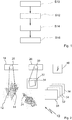
- Fig. 1 uses a schematically highly simplified flow diagram to illustrate an exemplary embodiment of a method for controlling devices in a sterile environment. The method is particularly suitable for controlling medical devices and equipment.
- the method comprises a first step S10, in which a virtual input field is defined on a real surface.
- Step S10 includes, for example, the selection of 2 or more points that represent the corner points or other points for describing the input field.
- the input field is, for example, rectangular or square. However, this is not to be understood as restrictive.
- the input field can also have different shapes.
- an input field of predefined dimensions by selecting a point.
- this can be expanded by the selection of a direction in addition to the selection of the point.
- the orientation of the input field can also be defined in this way.
- the (real) surface can basically be freely selected within wide limits. This can be, for example, a palm or a comparable surface on the skin of the operator or another person (back of the hand, arm, back, etc.). Furthermore, it can also be a surface that is fixed or movable in space, for example a surface of a device, a wall surface, a table surface, etc.
- a next step S12 relates to the detection of an operator input on the surface in the virtual input field.
- the detection can be done optically, for example by at least one camera.
- Embodiments are conceivable in which 2 or more cameras are combined with one another in order to be able to record the operator input precisely and reliably, even with a large degree of design freedom regarding the selection of the input field on the surface.
- the operator input can include, for example, a contact of a finger with the input field. Furthermore, the operator input can also include a movement and / or a contact of a marker in relation to the input field.
- the marker can be part of a stylus (stylus). However, the marker can also be attached to the finger or hand of the operator. It is also conceivable to use an optical marker, comparable to a laser pointer or a similar optical emitter. In this way, input can be made in the operating field even without direct contact. It goes without saying that appropriately upgraded sensors are provided for the detection.
- sensors can be used in the detection unit, which are based on different operating principles.
- optical sensors cameras, scanners, laser scanners, etc.
- electromagnetic sensors it is also conceivable to provide electromagnetic sensors and the like.
- the operator input can include an operator gesture.
- a gesture can take place in two-dimensional space. This way complex Operating commands are generated and transmitted. Such gestures can also simplify the selection of values from large value ranges. In addition, the uniqueness and reliability of the input can be increased by gesture control. This also applies if a considerable number of operating commands and corresponding gestures are provided.
- a further step S14 which follows the detection step S12 or can even overlap in time with the detection step S12, relates to the display of visual information in response to the input. In this way, an optical feedback can be provided.
- the visual information can be provided exactly in the input field in which the input was previously made. In this way, for example, the path of the operator gesture can be "traced". This increases the uniqueness of the operation.
- the visual feedback can also contain information other than an imitation of the control gesture, such as alphanumeric information, symbol representations, etc.
- the visual information can also be provided in an area that does not correspond to the area in which the input field is defined. This is conceivable, for example, if the operator makes the entry directly on the palm of his hand. The response can then take place in another area. This enables "blind” inputs because the operator can focus his attention on another surface.
- the method comprises a further step S16, which contains the execution of a function assigned to the input.
- the method can be used to control a wide range of functions, such as display functions, playback functions, Recording functions, lighting functions, adjustment functions, travel functions, drive functions, communication functions, etc.
- steps S10 to S16 can contain further steps and substeps which can be designed in accordance with the configurations and exemplary embodiments described herein.
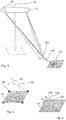
- FIG. 2 a schematic block diagram illustrates an embodiment of a system for controlling devices in a sterile environment, which according to at least in exemplary embodiments for performing the method Fig. 1 is designed.
- the system is designated 10 in total.
- the system 10 is designed to record operator inputs that are made in relation to a largely arbitrarily selectable surface 12.
- surface 12 is a palm.
- various other surfaces can also be used, such as wall surfaces, table surfaces, surfaces of devices, etc.
- the exemplary illustration of a hand or palm as a "carrier" of the surface 12 shows that the surface 12 does not necessarily have to be flat. In this respect, it is conceivable to use curved surfaces, uneven surfaces, but also planar (flat) surfaces.
- An input field 14 is defined in the surface 12.
- the definition of the input field 14 can, for example, in accordance with the method step S10 in the Fig. 1 illustrated procedures take place.
- the system 10 further comprises a detection unit, designated 18, which is designed, for example, as an optical detection unit.
- the detection unit 18 has at least one sensor 20, in accordance with the exemplary embodiment Fig. 2 the sensor on FIG. 20 is, for example, an optical sensor in the form of a camera. It goes without saying that other sensors can also be used in certain cases.
- the registration unit 18 may include a plurality of sensors 20. This can be useful if the surface 12 or the input field 14 are placed unfavorably in the room from the perspective of only one sensor.
- an operator can use 24 to make operator inputs in the input field 14.
- the pointer (s) 24 can be formed by fingers of one hand.
- a user it is conceivable for a user to use his left hand as an input field 14 and his right hand as a pointer 24, or vice versa.
- the operator input can basically include a single tap, but also a double tap. Furthermore, the operator input can include gestures, such as drawing a movement path in two-dimensional space.
- gestures are to be understood as operating inputs that go beyond a simple (single) tap.
- the pointer 24 can in principle also comprise a so-called marker.
- Markers can be designed as optical markers for optical detection. However, markers can also be designed as electromagnetic markers or in some other way, depending on the active principle used on the part of the detection unit.
- the detection unit 18 can detect the operator input.
- System 10 is further configured to provide visual information in response to operator input. This can be done, for example, using a display unit 28.
- the display unit 28 comprises, for example, at least one projection unit 30.
- Other configurations of display units 28 are also conceivable, for example those without projection units.
- the display unit 28 enables a visual feedback (optical feedback) to the operator, containing information regarding or in response to his operator input in the input field 14.
- the display unit 28 is configured, for example, to display visual information 34 on a display surface 32, for example by means of a projection.
- the display surface 32 is spaced from the surface 12 in which the input field 14 is defined.
- Visual information 34 can be displayed in the duty to display 32. This can include, for example, an input by a gesture, a "tracing" of the gesture. However, it is also conceivable to use a different representation of an alphanumeric or symbolic nature in response to the gesture.
- the visual information 34 to be displayed can actually be brought into line with the operating gesture.
- the visual information 34 may include "tracing" the path along the input fields S14 that corresponds to the gesture.
- the visual information 34 can be displayed with a delay such that the operator can again see the gesture he has just made.
- the display unit 28 may visually highlight the defined input field 14, for example by displaying a border.
- the system further comprises a control device, designated 40, which is coupled to the detection unit 18 and the display unit 28. Furthermore, the control device 40 is coupled to at least one medical device 50, 52, 54, 56 in order to control the at least one medical device 50, 52, 54, 56 on the basis of the operator input. It goes without saying that the controller 40 can also be coupled to other devices which can be controlled on the basis of the operator input detected and processed by the system 10.
- Fig. 3 illustrates an embodiment of a detection unit 18, which can be used for example in the system 10, that in Fig. 2 is shown.
- the detection unit 18 has a first sensor 20 and a second sensor 22. Both sensors are designed as cameras, for example. Other types of sensors are conceivable.
- the cameras can be designed to detect light in the visible range, but in principle also to detect light in the non-visible range, for example infrared radiation, ultraviolet radiation, etc.
- Fig. 3 further illustrates that a pointer 124 can be used for selection and input, which is designed, for example, as a stylus or in a similar manner.
- the pointer 124 is provided with at least one marker 126, which simplifies the detection and tracking by the detection unit 18. In this way, both simple and complex operating gestures can be reliably recorded in the input field 14.
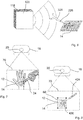
- FIG. 4 if a pointer 124 in the form of a stylus is used, see also the illustration in Fig. 3 .
- the pointer 124 is used to select two or more points, in particular corner points 60, in order to define the input field 14.
- corner points 60 In Fig. 4
- 4 corner points are selected to define a square / rectangular input field 14.
- Fig. 5 illustrates that the input field 14 can also be selected by placing a reference pointer 224, which is provided with a reference marker, on the selected surface.
- the reference pointer 224 has reference markers 226.
- the reference pointer 224 contains, for example, inherent directional information and possibly also inherent size information, so that in some circumstances the selection of only one point 62 with the reference pointer 224 is sufficient to adequately define the input field 14.
- FIG. 12 illustrates another exemplary embodiment of a capture unit 118 that is included in the system 10 of FIG Fig. 2 is usable.
- the detection unit 118 is designed, for example, as an electromagnetic detection unit. Accordingly, the detection unit 118 is provided with at least one electromagnetic sensor 120. It goes without saying that a plurality of such sensors can also be provided in the detection unit 118.
- entries can be made using a pointer 324, which is designed as an example as a stylus.
- the pointer 324 is adapted to the type of the detection unit. Accordingly, the pointer 324 is provided, for example, with at least one electromagnetic marker 326 or at least one electromagnetically detectable marker 326.
- the at least one marker 326 can be designed as an RFID marker or at least similarly to it. Such a marker 326 can be designed as an active marker or as a passive marker, depending on the specific application. However, even when using an electromagnetic detection unit 118, it is basically conceivable to dispense with a stylus as pointer 324. In other words, the at least one marker 326 can be attached, for example, to a finger or glove of the operator.
- Fig. 7 illustrates an embodiment of an acquisition unit 18, which is designed as an image acquisition unit and is provided with at least one image sensor 20 in the form of a camera.
- a detection range of the image sensor 20 is indicated at 70.
- a palm of the operator is selected as the surface 12 in which the input field 14 is defined.
- a finger (of the other hand) of the operator acts as pointer 24. In this way, control / operation can take place to a certain extent without physical interaction with foreign objects.
- Fig. 8 illustrates another conceivable embodiment in which a detection unit 18 is used which is designed as an optical detection unit. Accordingly, the detection unit 18 is provided with at least one optical sensor 20, analogously to the exemplary embodiments according to Fig. 2 , Fig. 3 and Fig. 7 .
- a light pointer 424 or a similarly designed optical pointer element for the operation, that is to say for the execution of operating gestures in the input field 14 on the selected surface 12.
- the light pointer 424 can be designed approximately analogously or at least similarly to a laser pointer.
- an optical marker 426 can be generated in the input field 14 from a distance, for example in the form of a light spot.
- the optical detection unit 18 monitors an area 70 in which the input field 14 is defined in the selected surface 12.
- the initial example according to Fig. 8 allows operation by gestures without tactile interaction with the surface 12.
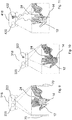
- the detection units are preferably designed for stereo detection or for spatial detection (3D detection). This has the advantage that, on the one hand, approaches to the input field 14 can already be detected. Even if the scope of the present disclosure is not about free gesture control in three-dimensional space, this information (in relation to the selected input field) can be used to increase the detection accuracy.
- the stereo detection or the spatial detection increases the accuracy even if the selected input field 14 is not ideally aligned with respect to a (single) sensor. This also applies, for example, if the input field 14 is not ideally planar, but curved.
- a detection unit 218 is provided, which can also be referred to as a 3D detection unit for stereo detection.
- the detection unit 218 has a first image sensor 220 and a second image sensor 222.
- the two image sensors 220, 222 are slightly offset from one another, so that stereoscopic acquisition and or even 3D acquisition is possible.
- Fig. 9 is indicated with 70 and 72 detection range of the two sensors 220, 222.
- the input field 14 selected as an example on a surface 12 of a hand is shown twice and with a slight offset in order to illustrate the stereo functionality.
- the finger of a hand which is also stereoscopically detectable and traceable, serves as the pointer 24.
- the input field 14 lies in the respective detection area 70, 72.
- the respective offset can be determined and processed in order to record spatial positions and / or gestures. This is also advantageous, for example, if curved, non-flat input fields 14 are used.
- Fig. 10 illustrates a detection unit 318 that is basically similar to the detection unit 218.
- the detection unit 318 is also designed for 3D detection or for spatial detection, special optical principles being used for detection.
- the detection unit 318 uses structured light, for example, a so-called stripe projection, dot pattern projection and / or other projection patterns. Combinations are possible.
- the principle is based on the fact that defined patterns are projected onto the input field 14, for example with a defined offset, and that not only 2D information but also spatial information can be recorded on the basis of the resulting distortions.
- the detection unit 318 also comprises at least one projection unit 322 for generating the defined light pattern, for example the stripe pattern, dot pattern and / or other projection pattern.
- the detection unit 418 which is designed to detect spatial information.
- the detection unit 418 combines a first sensor 420 and a second sensor 422.
- the first sensor 420 is designed, for example, as an optical sensor in the form of a camera (video camera).
- the second sensor 422 is designed, for example, as a so-called ToF camera (time-of-flight camera). Spatial information can also be recorded using the time-of-flight principle.
- the ToF camera 422 has a correspondingly configured light source, or is coupled to one. The light source emits pulsed or otherwise modulated light, which can be captured and processed by the ToF camera 422.
- an embodiment of a variant of the detection unit 418 is conceivable, in which only one ToF sensor 422 is used, in particular a single ToF sensor 422.
- the ToF camera 422 is designed, for example, to determine the time for its respective pixels that the light takes to the observed object (input field) and back to the camera. In this way, depth information can be determined.
Landscapes
- Engineering & Computer Science (AREA)
- General Engineering & Computer Science (AREA)
- Theoretical Computer Science (AREA)
- Human Computer Interaction (AREA)
- Physics & Mathematics (AREA)
- General Physics & Mathematics (AREA)
- User Interface Of Digital Computer (AREA)
- Apparatus Associated With Microorganisms And Enzymes (AREA)
Applications Claiming Priority (1)
| Application Number | Priority Date | Filing Date | Title |
|---|---|---|---|
| DE102018125956.5A DE102018125956A1 (de) | 2018-10-18 | 2018-10-18 | Verfahren und System zur Steuerung von Geräten in steriler Umgebung |
Publications (2)
| Publication Number | Publication Date |
|---|---|
| EP3644162A2 true EP3644162A2 (fr) | 2020-04-29 |
| EP3644162A3 EP3644162A3 (fr) | 2020-05-06 |
Family
ID=68295979
Family Applications (1)
| Application Number | Title | Priority Date | Filing Date |
|---|---|---|---|
| EP19203872.7A Ceased EP3644162A3 (fr) | 2018-10-18 | 2019-10-17 | Procédé et système de commande des appareils dans un environnement stérile |
Country Status (2)
| Country | Link |
|---|---|
| EP (1) | EP3644162A3 (fr) |
| DE (1) | DE102018125956A1 (fr) |
Families Citing this family (2)
| Publication number | Priority date | Publication date | Assignee | Title |
|---|---|---|---|---|
| DE102023112849A1 (de) * | 2023-05-16 | 2024-11-21 | Bayerische Motoren Werke Aktiengesellschaft | Steuerung eines Kraftfahrzeugs |
| DE102024104264A1 (de) | 2024-02-15 | 2025-08-21 | Dr. Ing. H.C. F. Porsche Aktiengesellschaft | Berührungssensitiver Bildschirm für ein Kraftfahrzeug |
Citations (5)
| Publication number | Priority date | Publication date | Assignee | Title |
|---|---|---|---|---|
| US6771294B1 (en) | 1999-12-29 | 2004-08-03 | Petri Pulli | User interface |
| DE102011078967A1 (de) | 2011-07-11 | 2013-01-17 | Leica Microsystems (Schweiz) Ag | Mikroskopgerät |
| DE102013110847B3 (de) | 2013-10-01 | 2015-01-22 | gomtec GmbH | Steuervorrichtung und Verfahren zum Steuern eines Robotersystems mittels Gestensteuerung |
| US20150323998A1 (en) * | 2014-05-06 | 2015-11-12 | Qualcomm Incorporated | Enhanced user interface for a wearable electronic device |
| WO2016151869A1 (fr) * | 2015-03-23 | 2016-09-29 | Nec Corporation | Appareil de traitement d'informations, procédé de traitement d'informations et programme |
Family Cites Families (2)
| Publication number | Priority date | Publication date | Assignee | Title |
|---|---|---|---|---|
| CN104583921A (zh) * | 2012-08-27 | 2015-04-29 | 西铁城控股株式会社 | 信息输入装置 |
| CN104866170B (zh) * | 2014-02-24 | 2018-12-14 | 联想(北京)有限公司 | 一种信息处理方法及电子设备 |
-
2018
- 2018-10-18 DE DE102018125956.5A patent/DE102018125956A1/de active Pending
-
2019
- 2019-10-17 EP EP19203872.7A patent/EP3644162A3/fr not_active Ceased
Patent Citations (5)
| Publication number | Priority date | Publication date | Assignee | Title |
|---|---|---|---|---|
| US6771294B1 (en) | 1999-12-29 | 2004-08-03 | Petri Pulli | User interface |
| DE102011078967A1 (de) | 2011-07-11 | 2013-01-17 | Leica Microsystems (Schweiz) Ag | Mikroskopgerät |
| DE102013110847B3 (de) | 2013-10-01 | 2015-01-22 | gomtec GmbH | Steuervorrichtung und Verfahren zum Steuern eines Robotersystems mittels Gestensteuerung |
| US20150323998A1 (en) * | 2014-05-06 | 2015-11-12 | Qualcomm Incorporated | Enhanced user interface for a wearable electronic device |
| WO2016151869A1 (fr) * | 2015-03-23 | 2016-09-29 | Nec Corporation | Appareil de traitement d'informations, procédé de traitement d'informations et programme |
Also Published As
| Publication number | Publication date |
|---|---|
| DE102018125956A1 (de) | 2020-04-23 |
| EP3644162A3 (fr) | 2020-05-06 |
Similar Documents
| Publication | Publication Date | Title |
|---|---|---|
| EP3305232B1 (fr) | Dispositif de commande et procede de commande pour l'opération d'un dispositif médical | |
| DE19958443C2 (de) | Bedieneinrichtung | |
| DE102018206406B3 (de) | Mikroskopiesystem und Verfahren zum Betrieb eines Mikroskopiesystems | |
| DE102012204018B4 (de) | Steuerungseinheit | |
| EP1998996B1 (fr) | Serveur interactif et procédé permettant de faire fonctionner le serveur interactif | |
| EP3458939B1 (fr) | Système et procédé d'interaction | |
| DE102012103030B3 (de) | Verfahren zur Bedienung eines Industrieroboters | |
| DE102012103032B3 (de) | Verfahren zur Bedienung eines Industrieroboters | |
| EP3781364A1 (fr) | Procédé d'utilisation par un utilisateur d'une cinématique actionnée à plusieurs membres, de préférence d'un robot, de préférence encore d'un robot à bras articulé, au moyen d'un dispositif d'affichage mobile | |
| DE102008041709A1 (de) | Medizinischer Arbeitsplatz und Bedienvorrichtung zum manuellen Bewegen eines Roboterarms eines medizinischen Arbeitsplatzes | |
| DE102019004233A1 (de) | Systeme und verfahren zum verfolgen von objekten | |
| EP2834715A1 (fr) | Procédé pour commander un robot industriel | |
| EP2953793B1 (fr) | Système de commande d'une presse à imprimer | |
| DE20001134U1 (de) | Operations-System | |
| DE102013203918A1 (de) | Verfahren zum Betreiben einer Vorrichtung in einer sterilen Umgebung | |
| DE19845027C2 (de) | Medizintechnisches System | |
| EP3644162A2 (fr) | Procédé et système de commande des appareils dans un environnement stérile | |
| DE102015211965A1 (de) | Berührungslose Gerätesteuerung im medizinischen Sterilbereich | |
| DE102018125592A1 (de) | Steuerungsanordnung, Verfahren zur Steuerung einer Bewegung eines Roboterarms und Behandlungsvorrichtung mit Steuerungsanordnung | |
| DE102008050542A1 (de) | Medizinisches Bildaufnahmesystem, Bedieneinrichtung und Verfahren zum Steuern einer Bildaufnahmevorrichtung | |
| DE10335369A1 (de) | Verfahren zum Bereitstellen einer berührungslosen Gerätefunktionssteuerung und Vorrichtung zum Durchführen des Verfahrens | |
| DE102013014889A1 (de) | Mauszeigersteuerung für eine Bedienvorrichtung | |
| DE102013208762A1 (de) | Intuitive Gestensteuerung | |
| DE102019108670B4 (de) | Verfahren zur Steuerung eines Geräts, insbesondere einer Handprothese oder eines Roboterarms, sowie Anordnung zur Durchführung des Verfahrens | |
| DE102007026120A1 (de) | Verfahren zur selbsttätigen Steuerung eines Zeigerelements in graphischen Nutzerschnittstellen eines digitalen Bildinformationssystems |
Legal Events
| Date | Code | Title | Description |
|---|---|---|---|
| PUAI | Public reference made under article 153(3) epc to a published international application that has entered the european phase |
Free format text: ORIGINAL CODE: 0009012 |
|
| STAA | Information on the status of an ep patent application or granted ep patent |
Free format text: STATUS: THE APPLICATION HAS BEEN PUBLISHED |
|
| PUAL | Search report despatched |
Free format text: ORIGINAL CODE: 0009013 |
|
| AK | Designated contracting states |
Kind code of ref document: A2 Designated state(s): AL AT BE BG CH CY CZ DE DK EE ES FI FR GB GR HR HU IE IS IT LI LT LU LV MC MK MT NL NO PL PT RO RS SE SI SK SM TR |
|
| AX | Request for extension of the european patent |
Extension state: BA ME |
|
| AK | Designated contracting states |
Kind code of ref document: A3 Designated state(s): AL AT BE BG CH CY CZ DE DK EE ES FI FR GB GR HR HU IE IS IT LI LT LU LV MC MK MT NL NO PL PT RO RS SE SI SK SM TR |
|
| AX | Request for extension of the european patent |
Extension state: BA ME |
|
| RIC1 | Information provided on ipc code assigned before grant |
Ipc: G06F 3/0346 20130101ALI20200331BHEP Ipc: G06F 3/03 20060101ALI20200331BHEP Ipc: G06F 3/01 20060101AFI20200331BHEP |
|
| STAA | Information on the status of an ep patent application or granted ep patent |
Free format text: STATUS: REQUEST FOR EXAMINATION WAS MADE |
|
| 17P | Request for examination filed |
Effective date: 20201103 |
|
| RBV | Designated contracting states (corrected) |
Designated state(s): AL AT BE BG CH CY CZ DE DK EE ES FI FR GB GR HR HU IE IS IT LI LT LU LV MC MK MT NL NO PL PT RO RS SE SI SK SM TR |
|
| STAA | Information on the status of an ep patent application or granted ep patent |
Free format text: STATUS: EXAMINATION IS IN PROGRESS |
|
| 17Q | First examination report despatched |
Effective date: 20211007 |
|
| P01 | Opt-out of the competence of the unified patent court (upc) registered |
Effective date: 20230527 |
|
| STAA | Information on the status of an ep patent application or granted ep patent |
Free format text: STATUS: THE APPLICATION HAS BEEN REFUSED |
|
| 18R | Application refused |
Effective date: 20230706 |