EP3644332A1 - Verfahren zur herstellung eines gewickelten magnetkerns und gewickelter magnetkern - Google Patents
Verfahren zur herstellung eines gewickelten magnetkerns und gewickelter magnetkern Download PDFInfo
- Publication number
- EP3644332A1 EP3644332A1 EP18821143.7A EP18821143A EP3644332A1 EP 3644332 A1 EP3644332 A1 EP 3644332A1 EP 18821143 A EP18821143 A EP 18821143A EP 3644332 A1 EP3644332 A1 EP 3644332A1
- Authority
- EP
- European Patent Office
- Prior art keywords
- multilayer body
- inner peripheral
- outer peripheral
- magnetic core
- peripheral surface
- Prior art date
- Legal status (The legal status is an assumption and is not a legal conclusion. Google has not performed a legal analysis and makes no representation as to the accuracy of the status listed.)
- Pending
Links
Images





Classifications
-
- H—ELECTRICITY
- H01—ELECTRIC ELEMENTS
- H01F—MAGNETS; INDUCTANCES; TRANSFORMERS; SELECTION OF MATERIALS FOR THEIR MAGNETIC PROPERTIES
- H01F41/00—Apparatus or processes specially adapted for manufacturing or assembling magnets, inductances or transformers; Apparatus or processes specially adapted for manufacturing materials characterised by their magnetic properties
- H01F41/02—Apparatus or processes specially adapted for manufacturing or assembling magnets, inductances or transformers; Apparatus or processes specially adapted for manufacturing materials characterised by their magnetic properties for manufacturing cores, coils, or magnets
- H01F41/0206—Manufacturing of magnetic cores by mechanical means
- H01F41/0213—Manufacturing of magnetic circuits made from strip(s) or ribbon(s)
-
- H—ELECTRICITY
- H01—ELECTRIC ELEMENTS
- H01F—MAGNETS; INDUCTANCES; TRANSFORMERS; SELECTION OF MATERIALS FOR THEIR MAGNETIC PROPERTIES
- H01F41/00—Apparatus or processes specially adapted for manufacturing or assembling magnets, inductances or transformers; Apparatus or processes specially adapted for manufacturing materials characterised by their magnetic properties
- H01F41/02—Apparatus or processes specially adapted for manufacturing or assembling magnets, inductances or transformers; Apparatus or processes specially adapted for manufacturing materials characterised by their magnetic properties for manufacturing cores, coils, or magnets
- H01F41/0206—Manufacturing of magnetic cores by mechanical means
- H01F41/0213—Manufacturing of magnetic circuits made from strip(s) or ribbon(s)
- H01F41/0226—Manufacturing of magnetic circuits made from strip(s) or ribbon(s) from amorphous ribbons
-
- H—ELECTRICITY
- H01—ELECTRIC ELEMENTS
- H01F—MAGNETS; INDUCTANCES; TRANSFORMERS; SELECTION OF MATERIALS FOR THEIR MAGNETIC PROPERTIES
- H01F27/00—Details of transformers or inductances, in general
- H01F27/24—Magnetic cores
- H01F27/25—Magnetic cores made from strips or ribbons
-
- H—ELECTRICITY
- H01—ELECTRIC ELEMENTS
- H01F—MAGNETS; INDUCTANCES; TRANSFORMERS; SELECTION OF MATERIALS FOR THEIR MAGNETIC PROPERTIES
- H01F3/00—Cores, Yokes, or armatures
- H01F3/04—Cores, Yokes, or armatures made from strips or ribbons
-
- H—ELECTRICITY
- H01—ELECTRIC ELEMENTS
- H01F—MAGNETS; INDUCTANCES; TRANSFORMERS; SELECTION OF MATERIALS FOR THEIR MAGNETIC PROPERTIES
- H01F1/00—Magnets or magnetic bodies characterised by the magnetic materials therefor; Selection of materials for their magnetic properties
- H01F1/01—Magnets or magnetic bodies characterised by the magnetic materials therefor; Selection of materials for their magnetic properties of inorganic materials
- H01F1/03—Magnets or magnetic bodies characterised by the magnetic materials therefor; Selection of materials for their magnetic properties of inorganic materials characterised by their coercivity
- H01F1/12—Magnets or magnetic bodies characterised by the magnetic materials therefor; Selection of materials for their magnetic properties of inorganic materials characterised by their coercivity of soft-magnetic materials
- H01F1/14—Magnets or magnetic bodies characterised by the magnetic materials therefor; Selection of materials for their magnetic properties of inorganic materials characterised by their coercivity of soft-magnetic materials metals or alloys
- H01F1/147—Alloys characterised by their composition
- H01F1/153—Amorphous metallic alloys, e.g. glassy metals
- H01F1/15333—Amorphous metallic alloys, e.g. glassy metals containing nanocrystallites, e.g. obtained by annealing
-
- H—ELECTRICITY
- H01—ELECTRIC ELEMENTS
- H01F—MAGNETS; INDUCTANCES; TRANSFORMERS; SELECTION OF MATERIALS FOR THEIR MAGNETIC PROPERTIES
- H01F17/00—Fixed inductances of the signal type
-
- H—ELECTRICITY
- H01—ELECTRIC ELEMENTS
- H01F—MAGNETS; INDUCTANCES; TRANSFORMERS; SELECTION OF MATERIALS FOR THEIR MAGNETIC PROPERTIES
- H01F17/00—Fixed inductances of the signal type
- H01F2017/0093—Common mode choke coil
Definitions
- the present invention relates to a method for manufacturing a non-circular wound magnetic core composed of a nano-crystallized soft magnetic alloy thin strip with resin impregnated between layers and the wound magnetic core.
- a common mode choke coil has been used as a way of curbing such problems, and an alloy magnetic material such as an amorphous alloy or a nano-crystallized soft magnetic alloy has been used as a magnetic core used therein.
- the alloy is manufactured as a soft magnetic alloy thin strip by a single roll method or the like, the thin strip is wound in a layered form, and the wound thin strip is used as a wound magnetic core.
- the nano-crystallized soft magnetic alloy thin strip is brittle, the thin strip may be deformed, partial contact may thus occur between the layers, and this may make it difficult to maintain the insulation, or there may also be a case in which the thin strip breaks due to the brittleness thereof.
- the thin strip may be used in a state in which the insulation between the layers is secured in the wound magnetic core by impregnating a resin between the thin strip layers, as disclosed in Patent Literatures 1 and 2, for example.
- the wound magnetic core may be formed into a non-circular shape such as a rectangular shape, a race track shape, or an oval shape for reasons such as facilitating a coil winding operation.
- a square magnetic core is obtained by winding a soft magnetic alloy thin strip around a first inner peripheral jig with an oval shape, then removing the inner peripheral jig with the oval shape, and inserting a second inner peripheral jig with a square columnar shape into the hollow portion.
- a wound magnetic core is disposed in a device in which a large number of wirings and electronic components are disposed. Therefore, the wound magnetic core may be designed into a shape that prevents the wound magnetic core from spatially interfering with the wirings and the electronic components. In this case, a required dimensional tolerance is frequently decided at a plurality of locations of a non-circular shape in a micron order.
- the magnetic core is a pressed powder body, the magnetic core is easily manufactured into a near net shape.
- a wound magnetic core soft magnetic alloy thin strip that can undergo nano-crystallization into a near net shape other than by forming the thin strip into a desired non-circular shape when the thin strip is wound or by producing a multilayer body wound into a circular shape and deforming the multilayer body into a desired non-circular shape.
- a problem in the manufacturing method of forming a thin strip into a desired non-circular shape when the thin strip is wound will be described.
- a way of winding the thin strip around a rotating non-circular bobbin is employed. Since the bobbin has a non-circular shape, the distance from a rotation axis to an outer periphery is not uniform, and an outer peripheral portion at which the distance is long has a large rotation radius, a winding speed thereof is high.
- the thin strip wound at this portion has higher tensile force than the thin strip wound at other portions. At the portion at which the thin strip is wound in a high tensile force state, contact between thin strip layers becomes tight. Therefore, the layers of the thin strip of the wound magnetic core obtained by this manufacturing method are brought into contact with each other, and an eddy current loss of the magnetic core increases.
- the inventors of the present invention employed a process for causing a resin to be impregnated between layers of a multilayer body in order to secure insulating properties between layers of a thin strip for manufacturing such a non-circular wound magnetic core,
- a resin to be impregnated between layers of a multilayer body in order to secure insulating properties between layers of a thin strip for manufacturing such a non-circular wound magnetic core
- the multilayer body with the resin impregnated therein swelled in a lamination direction, and as a result, it became difficult to manufacture a wound magnetic core within a required dimensional tolerance.
- an inner peripheral jig and an outer peripheral jig with shapes that entirely cover an inner peripheral side and an outer peripheral side of the wound multilayer body were produced, and a resin was caused to be impregnated while being maintained with the jigs in the lamination direction.
- a problem that inductance deteriorated is remained.
- An object of the invention is to provide a method for manufacturing a non-circular wound magnetic core composed of a nano-crystallized soft magnetic alloy thin strip and the wound magnetic core that easily curb a decrease in inductance due to resin impregnation.
- a method for manufacturing a non-circular wound magnetic core composed of a nano-crystallized soft magnetic alloy thin strip including: a step of acquiring a multilayer body by winding a soft magnetic alloy thin strip that can undergo nano-crystallization; a step of nano-crystallizing the soft magnetic alloy thin strip that can undergo nano-crystallization by inserting a heat treatment inner peripheral jig on the inner peripheral side of the multilayer body, maintaining the multilayer body in a non-circular shape when viewed in the axial direction, and subjecting the multilayer body maintained in the non-circular shape to heat treatment; and a step of maintaining the nano-crystallized multilayer body in the non-circular shape using resin impregnation inner peripheral and outer peripheral jigs and impregnating a resin between the layers of the multilayer body, in which the resin impregnation inner peripheral and outer peripheral jigs are shaped so as to not contact at least one of the inner peripheral surface
- the obtained multilayer body preferably has a circular shape when viewed in the axial direction and a space factor of the soft magnetic alloy thin strip is preferably equal to or greater than 70% and equal to or less than 85%.
- the heat treatment inner peripheral jig may be shaped to contact the inner peripheral surface of at least the part where the multilayer body has the large degree of curvature.
- the heat treatment inner peripheral jig may be shaped to maintain the entire periphery of the inner peripheral surface of the multilayer body.
- the multilayer body may also be maintained on the outer peripheral side using the heat treatment outer peripheral jig, and the heat treatment outer peripheral jig may be shaped to maintain at least a part of the outer peripheral surface of the multilayer body in the non-circular shape.
- non-circular shape may be a flat shape.
- non-circular shape may be a flat shape with at least a part that is recessed inward.
- the degree of curvature may be equal to or greater than 0.02.
- wound magnetic core may be used for a common mode choke coil.
- a wound magnetic core may be manufactured by the aforementioned manufacturing method.
- the inventors reviewed the reasons that inductance tends to deteriorate if a resin is impregnated in a non-circular wound magnetic core. Thus, the inventors found that the inductance tends to deteriorate because the thin strip gathers with high density in a lamination direction at a part where a degree of curvature is large, air gaps between layers are small, the resin is not sufficiently impregnated, thin strip layers are brought into contact with each other, and it is thus not possible to sufficiently prevent occurrence of an eddy current loss.
- the inventors conducted the following operation when the resin was impregnated in the multilayer body. First, they maintained a nano-crystallized multilayer body in a non-circular shape in a state in which the multilayer body is pinched with resin impregnation outer peripheral and inner peripheral jigs in the lamination direction in order for the dimension not to deviate from a target range due to swelling of the multilayer body in the lamination direction.
- the resin impregnation inner peripheral jig and the outer peripheral jig with shapes such that the inner peripheral jig and the outer peripheral jig do not contact at least either one of an inner peripheral surface or an outer peripheral surface of the multilayer body at a part where a degree of curvature of the multilayer body is large in order for the resin to be sufficiently impregnated at the part where the degree of curvature of the multilayer body is large.
- the part where the degree of curvature of the multilayer body is large is brought into a state in which the gaps of the thin strip layers tend to expand, and the resin thus tends to be sufficiently impregnated. Also, even if the resin is impregnated at that part, the shape of the part where the degree of curvature is large is substantially maintained due to rigidity of the nano-crystallized soft magnetic alloy thin strip since other parts are maintained in the non-circular shape with the inner peripheral jig and the outer peripheral jig. As a result, it is possible to maintain the non-circular shape state within a requested dimensional error and further to curb a decrease in inductance.
- a manufacturing method is a method for manufacturing a non-circular wound magnetic core composed of a nano-crystallized soft magnetic alloy thin strip, the method including: a step of acquiring a multilayer body by winding a soft magnetic alloy thin strip that can undergo nano-crystallization; a step of nano-crystallizing the soft magnetic alloy thin strip that can undergo nano-crystallization by inserting a heat treatment inner peripheral jig on the inner peripheral side of the multilayer body, maintaining the multilayer body in a non-circular shape when viewed in the axial direction, and subjecting the multilayer body maintained in the non-circular shape to a heat treatment; and a step of maintaining the nano-crystallized multilayer body in the non-circular shape by using resin impregnation inner peripheral and outer peripheral jigs, and impregnating a resin between the layers of the multilayer body, in which the resin impregnation inner peripheral and outer peripheral jigs are shaped so as
- the expression "shaped so as to not contact at least one of the inner peripheral surface and the outer peripheral surface of the multilayer body at a part where the multilayer body has a large degree of curvature” includes a shape in which the jigs are in partial contact with the inner peripheral surface or the outer peripheral surface at the part where the multilayer body has a large degree of curvature.
- the expression "shaped to contact” does not necessarily indicate a state in which the jigs and the inner peripheral surface or the outer peripheral surface of the multilayer body are in complete contact with each other over the entire part with the degree of curvature, and the jigs and the inner peripheral surface or the outer peripheral surface of the multilayer body may face each other in proximity with a clearance therebetween.
- the shapes of the jigs it is only necessary for the shapes of the jigs to be shapes that follow the shape of the part with the degree of curvature of the multilayer body in such a form that deformation of the multilayer body is curbed.
- the resin impregnation jigs are further preferably shaped so as to not contact any of the peripheral surfaces of the parts where the degrees of curvature are large at least on the inner peripheral side or the outer peripheral side of the multilayer body.
- a soft magnetic alloy thin strip that can undergo nano-crystallization will be described.
- the soft magnetic alloy thin strip that can undergo nano-crystallization is mainly an alloy thin strip in an amorphous state.
- composition of the alloy thin strip an alloy with a composition represented by the formula: (Fe1-aMa)100-x-y-z- ⁇ - ⁇ - ⁇ CuxSiyBzM' ⁇ M" ⁇ X ⁇ (atom%) (where M is Co and/or Ni, M' is at least one element selected from the group consisting of Nb, Mo, Ta, Ti, Zr, Hf, V, Cr, Mn, and W, M" is at least one element selected from the group consisting of Al, an element from the platinum group, Sc, a rear earth element, Zn, Sn, and Re, X is at least one element selected from the group consisting of C, Ge, P, Ga, Sb, In, Be, and As, and a, x, y, z, ⁇ , ⁇ , and ⁇ satisfy 0 ⁇ a 0.5, 0.1 ⁇ x ⁇ 3, 0 ⁇ y ⁇ 30, 0 ⁇ z ⁇ 25, 5 ⁇ y + z ⁇ 30,
- a soft magnetic alloy thin strip with a long shape that can undergo nano-crystallization can be obtained by melting the alloy with the aforementioned composition at a melting point or higher and rapidly solidifying the alloy by a single roll method.
- technologies known as methods for manufacturing an amorphous alloy thin strip and a nano-crystallized soft magnetic alloy thin strip can be used.
- the soft magnetic alloy thin strip with a thickness of equal to or less than 15 ⁇ m is useful in a wound magnetic core for a common mode choke coil since impedance in a high-frequency region (equal to or greater than 100 kHz) is easily improved. Note that it is only necessary for the thickness of the soft magnetic alloy thin strip to be equal to or greater than 5 ⁇ m and the thickness is further preferably equal to or greater than 7 ⁇ m.
- the long soft magnetic alloy thin strip obtained by the single roll method or the like is subjected to slit working as needed and is wound around a bobbin with a predetermined shape, thereby obtaining an annular multilayer body 1' illustrated in FIG. 5 .
- the multilayer body of the soft magnetic alloy thin strip is preferably wound into a circular shape when viewed in an axial direction such that the space factor is equal to or greater than 70% and equal to or less than 85%.
- An upper limit of the space factor is more preferably 80% and is further preferably 78%.
- a lower limit of the space factor is more preferably 72%.
- the multilayer body 1' obtained by winding the soft magnetic alloy thin strip preferably has a circular shape when viewed in the axial direction.
- the reason is as follows.
- the soft magnetic alloy thin strip is wound around a non-circular bobbin, thereby manufacturing the multilayer body 1a.
- distances between the rotation axis and the respective parts of the periphery thereof in the non-circular bobbin differ from each other, and that is, peripheral speeds at the respective parts differ from each other. Therefore, it is not possible to wind out the thin strip from a winding-out roll on a supply side with constant tensile force unless complicated tensile force control is performed.
- the distances between the thin strip layers also vary in the wound multilayer body, and the amount of resin filled varies. Therefore, inductance of the wound magnetic core tends to change. Also, the wound-out thin strip tends to break, and it may become difficult to wind the thin strip around the bobbin due to the variation in tensile force.
- the space factor If the space factor is high, it is difficult to establish insulation between layers even in a case in which resin impregnation is performed, and inductance tends to deteriorate.
- the reason is as follows.
- the resin In order to obtain more reliable insulation between the layers through the resin impregnation, the resin preferably permeates to the inside of the wound magnetic core.
- the reason for the deterioration of inductance is estimated to be that it becomes difficult to cause the resin to permeate to the inside of the magnetic core if the space factor is excessively high.
- the space factor of the soft magnetic alloy thin strip is equal to or less than 85%, the resin is easily caused to permeate to the inside of the wound magnetic core even if the multilayer body is deformed into a non-circular shape, and the insulation between the layers tends to be secured.
- the space factor is equal to or greater than 70%, high saturation magnetic flux density is easily obtained since an effective sectional area of the wound magnetic core is easily secured in comparison with the same wound magnetic core dimension. Therefore, the excellent magnetic properties that the soft magnetic alloy thin strip originally has are sufficiently utilized.
- the space factor in the invention is a proportion Sribon/Stotal of both an entire sectional area (except for a resin adhering to the surface of the wound magnetic core) Stotal when the wound magnetic core is cut along a plane including the winding axis and the cut surface is observed and a sectional area Sribon of the soft magnetic alloy thin strip calculated from both the sectional areas.
- the soft magnetic alloy thin strip that can undergo nano-crystallization is mainly a thin strip in an amorphous state and obtains a nano-crystallized structure in which equal to or greater than 50% of the composition has an average crystal particle diameter of equal to or less than 100 nm by being subjected to heat treatment at a temperature of equal to or greater than a crystallization start temperature. If the soft magnetic alloy thin strip has the aforementioned composition, the heat treatment for nano-crystallization is typically performed within a range of equal to or greater than 450 °C and equal to or less than 600 °C.
- the thin strip in an amorphous state has elasticity and is recovered even when bent to a degree of curvature to some extent, the thin strip with the nano-crystallized structure has high brittleness. Therefore, the wound multilayer body is deformed into a desired shape before the nano-crystallization, and a heat treatment for nano-crystallization is then performed thereon in a state in which the shape is maintained.
- the multilayer body composed of the thin strip in an amorphous state is maintained in the shape with a heat treatment jig for maintaining the shape.
- a heat treatment jig for maintaining the shape.
- the inner peripheral jig can be used alone while the outer peripheral jig may also be used.
- the heat treatment inner peripheral jig is preferably shaped to contact the inner peripheral surface of at least the part where the multilayer body has a large degree of curvature.
- the volume of the soft magnetic alloy thin strip that can undergo nano-crystallization is reduced by several % during the nano-crystallization since the crystal structure changes.
- the part where the degree of curvature is large is easily deformed, the dimension of the multilayer body is easily maintained in a desired shape even after the heat treatment process by using the heat treatment inner peripheral jig that is in contact at least with the inner peripheral surface of that part.
- the inner peripheral surface is deformed to shrink as a whole, it is further preferable to use a heat treatment inner peripheral jig with a shape that maintains the entire periphery of the inner peripheral surface of the multilayer body in order to maintain the desired shape.
- the multilayer body be maintained with the heat treatment inner peripheral jig and a heat treatment outer peripheral jig disposed on the outer peripheral side and that the heat treatment outer peripheral jig be shaped to maintain at least a part of the outer peripheral surface of the multilayer body in the non-circular shape.
- the heat treatment outer peripheral jig may be shaped to maintain the entire periphery of the outer peripheral surface of the multilayer body.
- the multilayer body is deformed into a non-circular shape, and it is preferable to apply the invention when the multilayer has a flat shape, in particular, a flat shape in which a ratio between a maximum diameter and a minimum diameter is equal to or greater than 2 or is further preferably equal to or greater than 3.
- a portion with a large degree of curvature tends to be generated as the degree of flatness becomes higher in the annular multilayer body, resin impregnation is sufficiently performed even at the part with the large degree of curvature by applying the invention.
- the multilayer body has a flat shape and has a shape with at least a part that is recessed inward, the part with a large degree of curvature is more likely to be formed. Therefore, it is more preferable to apply the present invention.
- the manufacturing method according to the invention is preferably applied in a case in which the degree of curvature on the inner peripheral surface side is equal to or greater than 0.02 at the part where the non-circular multilayer body has a large degree of curvature. Further, it is preferable to apply the invention in a case in which the degree of curvature is equal to or greater than 0.03 or is further preferably equal to or greater than 0.05.
- the degree of curvature is a reciprocal of a curvature radius R and is represented as 1/R (1/mm).
- the curvature radius is determined by an outline of the inner peripheral surface when the wound magnetic core is viewed in the axial direction. Even in a case in which the outline of the inner peripheral surface does not have a part with a complete arc shape at the inner peripheral surface, the shape can be approximated to an arc if a sufficiently minute length (the length of 3 mm at the curve portion in the invention) is provided. Also, it is possible to calculate the degree of curvature from the curvature radius R of the approximated arc.
- the manufacturing method according to the invention is preferably applied to a wound magnetic core with a height of equal to or greater than 20 mm in the winding axis direction.
- the manufacturing method according to the invention Although it is more difficult to sufficiently perform resin impregnation as the wound magnetic core is higher, it becomes easy to inhibit a decrease in inductance by applying the manufacturing method according to the invention. It is further preferable to apply the manufacturing method according to the invention to a wound magnetic core with a height of equal to or greater than 30 mm in the winding axis direction.
- the manufacturing method according to the invention is preferably applied to a wound magnetic core with a thickness of equal to or greater than 2 mm in the lamination direction. Although it is more difficult to sufficiently perform resin impregnation as the thickness in the lamination direction is thicker, it becomes easy to inhibit a decrease in inductance by applying the manufacturing method according to the invention. It is further preferable to apply the manufacturing method according to the invention to a wound magnetic core with a thickness of equal to or greater than 3 mm in the lamination direction.
- resin impregnation is performed. Note that the resin impregnation is performed for the purpose of securing insulation between the thin strip layers and other purposes include a role of maintaining the shape of the multilayer body and a role of preventing the thin strip from falling off.
- the nano-crystallized multilayer body is maintained in the non-circular shape with the resin impregnation inner peripheral jig and the outer peripheral jig in order to prevent deformation in the process of resin impregnation.
- the resin impregnation inner peripheral jig and the outer peripheral jig are shaped so as to not contact at least one of the inner peripheral surface and the outer peripheral surface of the multilayer body at the part where the multilayer body has a large degree of curvature.
- the expression that the resin impregnation inner peripheral jig and the outer peripheral jig "maintain the multilayer body in the non-circular shape” means that the shape is any shape as long as the amount of deformation of each part of the multilayer body can be curbed to be equal to or less than ⁇ 500 ⁇ m through the resin impregnation.
- a shape that enables curbing of the amount of deformation to be equal to or less than ⁇ 300 ⁇ m, or further preferably equal to or less than ⁇ 200 ⁇ m is more preferably employed.
- the resin preferably has viscosity of equal to or greater than 0.3 mPa ⁇ s and equal to or less than 10 Pa ⁇ s.
- the resin includes a resin with viscosity adjusted within the aforementioned range by being diluted with a solution such as an organic solvent.
- the viscosity of the resin affects how easily the resin enters between the layers. Since the content of the solution in the resin with the viscosity of less than 0.3 mPa ⁇ s is excessively high, it is difficult to increase a resin filling rate, which will be described later, after the solution is evaporated even if the resin is sufficiently impregnated between the layers of the multilayer body. Meanwhile, if the viscosity is greater than 10 mPa ⁇ s, it is difficult to sufficiently impregnate the resin between the layers. Also, it takes a long time to impregnate the resin, which leads to an increase in manufacturing costs.
- An epoxy resin, a polyimide resin, or the like is conceivable as the resin used in the invention, and an epoxy resin is preferably used in terms of heat resistance and temperature properties. Also, it is possible to use a thermosetting resin.
- a pressure applied when the resin is impregnated is preferably equal to or greater than -0.05 MPa and equal to or less than 0 MPa with respect to atmospheric pressure. If the pressure is excessively low, the solvent is significantly vaporized. In order to inhibit consumption of the solvent through vaporization and to improve operation efficiency, the pressure is preferably equal to or greater than -0.05 MPa with respect to atmospheric pressure. On the other hand, if the pressure is higher than atmospheric pressure, air between the layers is not pushed out, and entry of the resin between the layers is easily prevented.
- a winding is wound directly or with a core case after insertion into a core case around the wound magnetic core with the resin impregnated.
- insulation may become insufficient if scratching occurs in an electric line due to an edge of the wound magnetic core after the impregnation or the edge of the wound magnetic core after the impregnation is not sufficiently covered with the resin. There is a probability of this leading to a serious accident such as a fire.
- Such a problem can be solved by winding the winding after the wound magnetic core is inserted into the core case.
- the wound magnetic core according to the invention is preferably used for a common mode choke coil.
- a wound magnetic core for a common mode choke coil used in a vehicle is required to have impact resistance and vibration resistance.
- the wound magnetic core according to the invention has excellent reliability since the resin is easily impregnated even at a part where the degree of curvature is high and breakage or peeling of the thin strip hardly occurs.
- a soft magnetic alloy thin strip that can undergo nano-crystallization was wound, thereby preparing a circular multilayer body 1' as illustrated in FIG. 5 .
- a soft magnetic alloy thin strip with a composition of Fe ba1 Cu 1 Nb 2.5 Si 13.5 B 7 (at%) with a width of 40 mm and a thickness of 14 ⁇ m was used.
- the multilayer body 1' was obtained by winding the soft magnetic alloy thin strip that can undergo nano-crystallization around a cylindrical bobbin with an outer diameter of 63 mm such that the outer diameter became 117 mm, the inner diameter became 113 mm, the height became 40 mm, the thickness in the lamination direction became 4 mm, and the space factor became 75%.
- the respective diagrams are for schematically explaining the shapes, and the dimensions may be appropriately changed.
- the multilayer body 1' was deformed into a flat shape using an inner peripheral jig illustrated in FIG. 6 .
- a ratio between a maximum diameter and a minimum diameter of a multilayer body 1a deformed into a flat shape was 3.
- FIG. 6(a) is a perspective view of a heat treatment inner peripheral jig 5a.
- FIG. 6(b) is a perspective view from another angle.
- the inner peripheral jig 5a included a contact surface 51a formed to be brought into contact with an inner peripheral surface of the multilayer body and hold the multilayer body in a desired shape.
- the inner peripheral jig 5a included a flange 52a formed to abut on an end of the multilayer body 1' in the axial direction in the embodiment.
- the contact surface 51a was inserted on an inner peripheral side of the multilayer body 1' while the multilayer body 1' was formed into a flat shape, and the multilayer body 1' was deformed into a desired non-circular shape along a peripheral side surface of the contact surface 51a.
- FIG. 7 is a perspective view illustrating a state in which inner peripheral jigs 5a1 and 5a2 were inserted into the multilayer body 1'.
- the inner peripheral jigs 5al and 5a2 had the same shape and were inserted on the inner peripheral side of the multilayer body 1' from both sides.
- the contact surface 51a of the inner peripheral jig 5a has a shape in contact with the entire periphery of the inner peripheral surface of the multilayer body 1'. In this manner, the inner peripheral jig 5a maintains the entire inner peripheral surface of the multilayer body 1' in a desired non-circular shape.
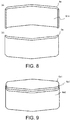
- FIG. 8(a) is a perspective view of the heat treatment outer peripheral jig 6a.
- FIG. 8(b) is a perspective view of the outer peripheral jig 6a from another angle.
- the outer peripheral jig 6a included a contact surface 61a formed for being brought into contact with an outer peripheral surface of the multilayer body to maintain the multilayer body in a desired non-circular shape.
- Two outer peripheral jigs 6a (outer peripheral jigs 6a1 and 6a2) were used to cause the contact surface 61a of the outer peripheral jigs 6a1 and 6a2 to abut the multilayer body 1'.
- the distance between the outer peripheral jigs 6a1 and 6a2 was gradually narrowed, and the multilayer body 1' was deformed into a shape that followed the contact surface 61a. Thereafter, the inner peripheral jig 5a in FIG. 6 was inserted into the multilayer body 1' that is deformed into the non-circular shape.
- FIG. 9 illustrates a state in which the outer peripheral jigs 6a1 and 6a2 are further used in comparison with the state in FIG. 7 .
- the multilayer body 1' was maintained in the non-circular shape with the inner peripheral jigs 5a1 and 5a2 and the outer peripheral jigs 6a1 and 6a2.
- a heat treatment for nano-crystallization was performed on the multilayer body 1' in the state of FIG. 7 or FIG. 9 .
- a means for heating the multilayer body 1' in a nitrogen atmosphere at 580 °C for 1 hour was employed.
- the invention is not limited to the embodiment, and the heat treatment may also be performed in a magnetic field.
- the multilayer body 1a Since elasticity of the thin strip after nano-crystallization decreased, the multilayer body 1a was not deformed and was maintained in the non-circular shape as illustrated in FIG. 2 even when the inner peripheral jigs and the outer peripheral jigs were removed. Note that in the embodiment, the part R represented by the circle of the dashed line in FIG. 2 corresponded to the part where the non-circular multilayer body had a large degree of curvature.
- Resin impregnation inner peripheral and outer peripheral jigs were disposed on the multilayer body 1a in FIG. 2 .
- the multilayer body 1a was maintained in the non-circular shape, and these jigs were brought into a state in which the inner peripheral jig and the outer peripheral jig were not in contact with at least one of the inner peripheral surface and the outer peripheral surface of the multilayer body at the part where the multilayer body had a large degree of curvature.
- these jigs were brought into a state in which the inner peripheral jig and the outer peripheral jig were not in contact with at least one of the inner peripheral surface and the outer peripheral surface of the multilayer body at the part where the multilayer body had a large degree of curvature.
- FIG. 3 is a diagram illustrating the resin impregnation inner peripheral jig 2a used in the embodiment.
- the inner peripheral jig 2a was shaped to contact the inner peripheral surface of the multilayer body at the part where the multilayer body had the large degree of curvature, and in the embodiment, the inner peripheral jig 2a had a contact surfaca for maintaining the entire periphery of the internal peripheral surface of the multilayer body.
- the contact surface 21a in the embodiment had the same shape as the upper and lower contact surfaces 51a in a state in which the heat treatment inner peripheral jigs 5a1 and 5a2 abutted.
- FIG. 4 is a diagram illustrating a resin impregnation outer peripheral jig 4a used in the embodiment.
- FIG. 4(a) is a perspective view of the resin impregnation outer peripheral jig 4a.
- FIG. 4(b) is a perspective view of the outer peripheral jig 4a from another angle.
- the outer peripheral jig 4a was shaped so as to not contact the outer peripheral surface of the multilayer body at the part where the multilayer body had a large degree of curvature while being in contact with at least a part of the outer peripheral surface of the multilayer body to maintain the multilayer body in the non-circular shape.
- the resin impregnation outer peripheral jig 4a had a contact surface 41a that was brought into contact with the outer peripheral surface of the multilayer body to maintain the desired non-circular shape.
- FIG. 1 illustrates a state in which two jigs, namely the inner peripheral jig 2a in FIG. 3 and the outer peripheral jig 4a in FIG. 4 , are disposed on the multilayer body 1a in FIG. 2 .
- Resin impregnation was performed on the multilayer body 1a in the state in FIG. 1 .
- an epoxy resin was used, and the viscosity of the used epoxy resin was adjusted to 0.5 mPa ⁇ s by diluting it with an organic solvent (acetone).
- the multilayer body was dipped into the diluted epoxy resin, thereby impregnating the resin.
- a pressure applied when the resin was impregnated was set to be atmospheric pressure. After the resin was impregnated, heat was applied, and the resin was thus caused to be cured.
- the wound magnetic core obtained in the embodiment exhibited a high inductance value in comparison with a wound magnetic core manufactured by holding both the inner peripheral surface and the outer peripheral surface with the resin impregnation inner peripheral jig and the outer peripheral jig at the part where the multilayer body had a large degree of curvature.
- FIG. 10 is a diagram illustrating an embodiment in which the shape of the multilayer body 1a is the same as that in FIG. 2 while the resin impregnation jigs have parts that are brought into contact with neither the inner peripheral surface nor the outer peripheral surface of the multilayer body at the part where the multilayer body has the large degree of curvature.
- Resin impregnation inner peripheral jig 2b and outer peripheral jigs 4b1 and 4b2 were disposed on the multilayer body 1a in FIG. 2 .
- the multilayer body 1a was maintained in the non-circular shape, and these jigs were brought into a state in which the jigs were in contact with neither the inner peripheral surface nor the outer peripheral surface at the part where the multilayer body had a large degree of curvature. Detailed description will be given below.
- FIG. 11 is a diagram illustrating the resin impregnation inner peripheral jig 2b used in the embodiment.
- the inner peripheral jig 2b had a contact surface 21b that was not brought into contact with the inner peripheral surface of the multilayer body at the part where the degree of curvature was large while being brought into contact with at least a part of the inner peripheral surface of the multilayer body to maintain the multilayer body in a non-circular shape.
- an outer peripheral jig with the same shape as the heat treatment outer peripheral jig illustrated in FIG. 8 was used (not illustrated).
- the outer peripheral jig was shaped so as to not contact the outer peripheral surface of the multilayer body at the part where the degree of curvature was large while being brought into contact with at least a part of the outer peripheral surface of the multilayer body to maintain the multilayer body in a non-circular shape.
- FIG. 10 is a diagram illustrating a state in which the inner peripheral jig 2b in FIG. 11 and two outer peripheral jigs (4b1 and 4b2) with the same shape as in FIG. 8 are disposed on the multilayer body 1a in FIG. 2 .
- the multilayer body 1a was adapted such that the inner peripheral surface of the multilayer body was not brought into contact with the inner peripheral jig 2b at the part where the degree of curvature was large.
- the outer peripheral surface of the multilayer body was partially maintained while the part where the degree of curvature was large included a part that was not brought into contact with the outer peripheral jigs 4b1 and 4b2.
- Inductance of the manufactured wound magnetic core was a value that was able to be applied to practical use similarly to other embodiments described above even when the resin impregnation jigs according to the embodiment were used.
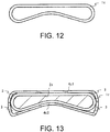
- FIG. 12 illustrates the shape of a multilayer body 1c according to another embodiment.
- the multilayer body in FIG. 12 is a non-circular multilayer body when viewed in the axial direction.
- the multilayer body 1c had a flat shape with at least a part that is recessed inward.
- a ratio between the maximum diameter (the diameter in the horizontal direction in the drawing) and the minimum diameter (the diameter in the vertical direction in the drawing) was 4.8.
- FIG. 14 is a diagram illustrating a state in which the shape of the multilayer body 1c is maintained with heat treatment outer peripheral jigs 6c1 and 6c2 and an inner peripheral jig 5c. Heat treatment for nano-crystallization was performed on the multilayer body 1c in this state.
- the inner peripheral jig 5c was shaped to contact the entire inner peripheral surface of the multilayer body 1c.
- the outer peripheral jigs 6c1 and 6c2 were also shaped to contact the entire outer peripheral surface of the multilayer body 1c in a state in which both the jigs were combined in the embodiment.
- FIG. 13 is a diagram illustrating a state in which the shape of the multilayer body 1c is maintained with the resin impregnation outer peripheral jigs 4c1 and 4c2 and inner peripheral jig 2c. Resin impregnation was performed on the multilayer body 1c in this state.
- the inner peripheral jig 2c was shaped to contact the inner peripheral surface of the multilayer body at the part where the multilayer body 1c had a large degree of curvature.
- the inner peripheral jig 2c was shaped to contact the entire inner peripheral surface of the multilayer body.
- the outer peripheral jigs 4c1 and 4c2 were shaped so as to not contact the outer peripheral surface of the multilayer body at the part where the degree of curvature was large while being brought into contact with at least a part of the outer peripheral surface of the multilayer body 1c to maintain the multilayer body 1c in the non-circular shape.
- the outer peripheral jigs 4c1 and 4c2 were brought into partial contact with the outer peripheral surface at the part where the multilayer body had a large degree of curvature while most parts of the outer peripheral jigs 4c1 and 4c2 were not in contact with the outer peripheral surface, and a space 3 was present on an outer peripheral side of the part where the multilayer body had a large degree of curvature.
- the wound magnetic core according to the embodiment had a height of 40 mm and a thickness of 4 mm in the lamination direction.
- Inductance of the manufactured wound magnetic core was a value that was able to be applied to practical use similarly to other embodiments described above even when the resin impregnation jigs according to the embodiment were used.
- FIG. 15 illustrates an embodiment in which the shape of the multilayer body is the same as that in FIG. 12 while shapes of resin impregnation jigs are different.
- Resin impregnation outer peripheral jigs 4d1 and 4d2 were shaped to contact the outer peripheral surface of the multilayer body 1c at the part where the multilayer body 1c had a large degree of curvature.
- the resin impregnation inner peripheral jig 2d was shaped so as to not contact the inner peripheral surface of the multilayer body at the part where the degree of curvature was large while being brought into contact with at least a part of the inner peripheral surface of the multilayer body 1c to maintain the multilayer body 1c in the non-circular shape.
- outer peripheral jigs 4d1 and 4d2 were shaped to maintain the entire periphery of the outer peripheral surface of the multilayer body 1c in the embodiment.
- the space 3 was present on the inner peripheral surface side of the part where the multilayer body 1c had a large degree of curvature.
- the resin was impregnated in the multilayer body 1c in this state.
- Inductance of the manufactured wound magnetic core was a value that was able to be applied to practical use similarly to other embodiments described above even when the resin impregnation jigs according to the embodiment were used.
- FIG. 16 illustrates a shape of a multilayer body according to another embodiment.
- the multilayer body 1e in FIG. 16 was a non-circular multilayer body when viewed in the axial direction.
- the multilayer body 1e had a flat shape with at least a part that is recessed inward.
- a ratio between the maximum diameter (the diameter in the horizontal direction in the drawing) and the minimum diameter (the diameter in the vertical direction in the drawing) was 4.4.
- FIG. 18 is a diagram illustrating a state in which the shape of the multilayer body 1e is maintained with outer peripheral jigs 6e1 and 6e2 and an inner peripheral jig 5e for heat treatment. Heat treatment for nano-crystallization was performed on the multilayer body 1e in this state.
- the inner peripheral jig 5e was shaped to contact the entire inner peripheral surface of the multilayer body 1e.
- the outer peripheral jigs 6e1 and 6e2 were also shaped to contact the entire outer peripheral surface of the multilayer body 1e in which both jigs were combined in the embodiment.
- FIG. 17 is a diagram illustrating a state in which the shape of the multilayer body 1e was maintained with resin impregnation outer peripheral jigs 4e1 and 4e2 and inner peripheral jig 2e. Resin impregnation was performed on the multilayer body 1e in this state.
- the inner peripheral jig 2e was shaped to contact the inner peripheral surface of the multilayer body at the part where the multilayer body 1e had a large degree of curvature
- the outer peripheral jigs 4e1 and 4e2 were shaped so as to not contact the outer peripheral surface of the multilayer body at the part where the multilayer body had a large degree of curvature while being brought into contact with at least a part of the outer peripheral surface of the multilayer body to maintain the multilayer body in a non-circular shape.
- the outer peripheral jigs 4e1 and 4e2 were brought into partial contact with the outer peripheral surface at the part where the multilayer body had a large degree of curvature while most parts of the outer peripheral jigs 4e1 and 4e2 were not in contact with the outer peripheral surface. Also, the space 3 was present on an outer peripheral side of the part where the multilayer body 1e had a large degree of curvature.
- the wound magnetic core according to the embodiment had a height of 40 mm and a thickness of 4 mm in the lamination direction.
- Inductance of the manufactured wound magnetic core was a value that was able to be applied to practical use similarly to other embodiments described above even when the resin impregnation jigs according to the embodiment were used.
- FIG. 19 illustrates an embodiment in which the shape of the multilayer body is the same as that in FIG. 16 while shapes of resin impregnation jigs are different.
- Resin impregnation outer peripheral jigs 4f1 and 4f2 were shaped to contact the outer peripheral surface of the multilayer body at a part where a multilayer body 1e had a large degree of curvature.
- a resin impregnation inner peripheral jig 2f was shaped to contact the inner peripheral surface of the multilayer body If to maintain the multilayer body in a non-circular shape, but does not contact the inner peripheral surface of the multilayer body at the part where the multilayer body had a large degree of curvature.
- outer jigs 4f1 and 4f2 were shaped to maintain the entire periphery of the outer peripheral surface of the multilayer body 1e in the embodiment.
- the space 3 was present on the inner peripheral surface side of the part where the multilayer body 1e had a large degree of curvature.
- the resin was impregnated in the multilayer body 1e in this state.
- Inductance of the manufactured wound magnetic core was a value that was able to be applied to practical use similarly to other embodiments described above even when the resin impregnation jigs according to the embodiment were used.
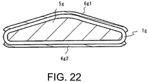
- FIG. 20 illustrates a shape of a multilayer body 1g according to another embodiment.
- the multilayer body in FIG. 20 was a non-circular multilayer body when viewed in the axial direction.
- the multilayer body 1g had a flat shape of substantially an isosceles triangle.
- a ratio between the maximum diameter (the diameter in the horizontal direction in the drawing) and the minimum diameter (the diameter in the vertical direction in the drawing) was 5.
- FIG. 22 is a diagram illustrating a state in which the shape of the multilayer body 1g is maintained with outer peripheral jigs 6g1 and 6g2 and an inner peripheral jig 5g for heat treatment. Heat treatment for nano-crystallization was performed on the multilayer body 1g in this state.
- the inner peripheral jig 5g was shaped to contact the entire inner peripheral surface of the multilayer body 1g.
- the outer peripheral jigs 6g1 and 6g2 were shaped to contact the outer peripheral surface of the multilayer body 1g other than the part where the multilayer body 1g had a large degree of curvature.
- FIG. 21 is a diagram illustrating a state in which the shape of the multilayer body 1g is maintained with resin impregnation outer peripheral jigs 4g1 and 4g2 and inner peripheral jig 2g. Resin was impregnated in the multilayer body 1g in this state. In this manner, the multilayer body 1g was maintained in a non-circular shape, and these jigs were brought into contact with neither the inner peripheral surface nor the outer peripheral surface of the multilayer body at the part where the multilayer body 1g had a large degree of curvature.
- the inner peripheral jig 2g was brought into contact with at least a part of the inner peripheral surface of the multilayer body to maintain the multilayer body in a non-circular shape while not being brought into contact with the inner peripheral surface of the multilayer body at the part where the multilayer body had a large degree of curvature. Also, the space 3 was present on the inner peripheral side of the part where the multilayer body 1g had a large degree of curvature.
- outer peripheral jigs 4g1 and 4g2 were brought into partial contact with the outer peripheral surface at the part where the multilayer body had a large degree of curvature on both sides when viewed in the axial direction while most parts of the outer peripheral jigs 4g1 and 4g2 were not in contact with the outer peripheral surface.
- the wound magnetic core according to the embodiment had a height of 40 mm and a thickness of 4 mm in the lamination direction.
- Inductance of the manufactured wound magnetic core was a value that was able to be applied to practical use similarly to other embodiments described above even when the resin impregnation jigs according to the embodiment were used.
Landscapes
- Engineering & Computer Science (AREA)
- Power Engineering (AREA)
- Manufacturing & Machinery (AREA)
- Manufacturing Cores, Coils, And Magnets (AREA)
- Coils Or Transformers For Communication (AREA)
Applications Claiming Priority (2)
| Application Number | Priority Date | Filing Date | Title |
|---|---|---|---|
| JP2017121209 | 2017-06-21 | ||
| PCT/JP2018/023228 WO2018235800A1 (ja) | 2017-06-21 | 2018-06-19 | 巻磁心の製造方法、及び巻磁心 |
Publications (2)
| Publication Number | Publication Date |
|---|---|
| EP3644332A1 true EP3644332A1 (de) | 2020-04-29 |
| EP3644332A4 EP3644332A4 (de) | 2021-03-10 |
Family
ID=64737042
Family Applications (1)
| Application Number | Title | Priority Date | Filing Date |
|---|---|---|---|
| EP18821143.7A Pending EP3644332A4 (de) | 2017-06-21 | 2018-06-19 | Verfahren zur herstellung eines gewickelten magnetkerns und gewickelter magnetkern |
Country Status (5)
| Country | Link |
|---|---|
| US (1) | US11636974B2 (de) |
| EP (1) | EP3644332A4 (de) |
| JP (1) | JP6601596B2 (de) |
| CN (1) | CN110291601B (de) |
| WO (1) | WO2018235800A1 (de) |
Families Citing this family (4)
| Publication number | Priority date | Publication date | Assignee | Title |
|---|---|---|---|---|
| DE112020000679T5 (de) * | 2019-02-05 | 2021-11-04 | Hitachi Metals, Ltd. | Gewickelter Magnetkern, Legierungskern und Verfahren zur Herstellung eines gewickelten Magnetkerns |
| JP2021005645A (ja) * | 2019-06-26 | 2021-01-14 | 学校法人トヨタ学園 | 積層鉄心およびその製造方法、その積層鉄心を用いた電気デバイス |
| JP7501890B2 (ja) * | 2020-03-30 | 2024-06-18 | 北川工業株式会社 | 積層コア及びノイズフィルタ |
| CN112430446B (zh) * | 2020-11-24 | 2022-09-13 | 飞竞电机(深圳)有限公司 | 一种用于非晶条带粘接和绝缘的粘合剂及其制备方法和使用方法 |
Family Cites Families (13)
| Publication number | Priority date | Publication date | Assignee | Title |
|---|---|---|---|---|
| JPS57148561A (en) * | 1981-03-09 | 1982-09-13 | Matsushita Electric Ind Co Ltd | Manufacture of wound core |
| JPS57193014A (en) * | 1981-05-22 | 1982-11-27 | Toshiba Corp | Manufacture of wound core |
| JPS60250612A (ja) * | 1984-05-25 | 1985-12-11 | Matsushita Electric Works Ltd | アモルフアス磁心の製法 |
| JPS62286214A (ja) | 1986-06-05 | 1987-12-12 | Hitachi Metals Ltd | アモルフアス磁心の製造方法 |
| JP2612305B2 (ja) * | 1988-05-17 | 1997-05-21 | 株式会社ダイヘン | 巻鉄心の製造方法 |
| JP3388247B2 (ja) * | 1992-10-13 | 2003-03-17 | 日立金属株式会社 | 巻磁心およびその製造方法 |
| JPH07220941A (ja) * | 1994-02-07 | 1995-08-18 | Daihen Corp | 電気機器用アモルファス鉄心及びその製造方法 |
| JPH0845723A (ja) * | 1994-08-01 | 1996-02-16 | Hitachi Metals Ltd | 絶縁性に優れたナノ結晶合金薄帯およびナノ結晶合金磁心ならびにナノ結晶合金薄帯の絶縁皮膜形成方法 |
| JPH0897063A (ja) * | 1994-09-28 | 1996-04-12 | Aichi Electric Co Ltd | 巻鉄心の成形装置 |
| JP2004039710A (ja) | 2002-07-01 | 2004-02-05 | Hitachi Metals Ltd | 巻磁心、これを用いたコイル及び巻磁心の製造方法 |
| JP2008196006A (ja) * | 2007-02-13 | 2008-08-28 | Hitachi Metals Ltd | Fe基ナノ結晶軟磁性合金、アモルファス合金薄帯およびFe基ナノ結晶軟磁性合金の製造方法並びに磁性部品 |
| US20170011829A1 (en) * | 2014-02-17 | 2017-01-12 | Hitachi Metals, Ltd. | Core for high-frequency transformer, and manufacturing method therefor |
| JP2016163018A (ja) | 2015-03-05 | 2016-09-05 | Necトーキン株式会社 | 角型磁心の製造方法及び治具 |
-
2018
- 2018-06-19 WO PCT/JP2018/023228 patent/WO2018235800A1/ja not_active Ceased
- 2018-06-19 CN CN201880011121.2A patent/CN110291601B/zh active Active
- 2018-06-19 EP EP18821143.7A patent/EP3644332A4/de active Pending
- 2018-06-19 US US16/490,563 patent/US11636974B2/en active Active
- 2018-06-19 JP JP2019525619A patent/JP6601596B2/ja active Active
Also Published As
| Publication number | Publication date |
|---|---|
| JP6601596B2 (ja) | 2019-11-06 |
| WO2018235800A1 (ja) | 2018-12-27 |
| US11636974B2 (en) | 2023-04-25 |
| JPWO2018235800A1 (ja) | 2019-12-19 |
| US20200075236A1 (en) | 2020-03-05 |
| CN110291601A (zh) | 2019-09-27 |
| EP3644332A4 (de) | 2021-03-10 |
| CN110291601B (zh) | 2022-01-04 |
Similar Documents
| Publication | Publication Date | Title |
|---|---|---|
| EP3644332A1 (de) | Verfahren zur herstellung eines gewickelten magnetkerns und gewickelter magnetkern | |
| US11723182B2 (en) | Shielding film and method for producing a shielding film | |
| KR100831804B1 (ko) | 인덕턴스 소자와 그 제조 방법 | |
| EP2139011B1 (de) | Magnetkern für eine antenne, verfahren zur herstellung eines magnetkerns für eine antenne und antenne | |
| EP2369678A1 (de) | Antennenkern und verfahren zu seiner herstellung sowie antenne und erfassungssystem dafür | |
| JP6786841B2 (ja) | 磁心およびその製造方法、並びに車載用部品 | |
| US20230106099A1 (en) | Non oriented electrical steel sheet, iron core, manufacturing method of iron core, motor, and manufacturing method of motor | |
| US20130147596A1 (en) | Reactor Device | |
| US11859265B2 (en) | Non oriented electrical steel sheet, iron core, manufacturing method of iron core, motor, and manufacturing method of motor | |
| WO2021200514A1 (ja) | 積層コア及びノイズフィルタ | |
| US20190180932A1 (en) | Core for current transformer | |
| JP2009114511A (ja) | 軟磁性金属箔の製造方法 | |
| JP2007221869A (ja) | 積層体 | |
| JP2023126149A (ja) | ノイズ対策用環状磁性体 | |
| JP2021512578A (ja) | 電磁鋼ラミネーションのスタックを製造する方法及びそれにより製造されたスタック | |
| JP2007281314A (ja) | 軟磁性合金薄帯積層体およびその製造方法 | |
| JP4851640B2 (ja) | 加速器用アモルファスコア及びそれを用いた加速器 | |
| KR102953295B1 (ko) | 시트 형상 자성 부재 | |
| US20240204632A1 (en) | Method for manufacturing laminated core | |
| WO2025110248A1 (ja) | ステータコア、電動機および発電機 | |
| CN120476455A (zh) | 层叠芯、噪声滤波器、磁芯 | |
| CN117918033A (zh) | 片状磁性构件 | |
| JP2025118235A (ja) | 磁性コア、及びノイズフィルタ | |
| KR20260061252A (ko) | 스테이터 코어, 전동기 및 발전기 | |
| JPS594005A (ja) | 巻鉄心の製造方法 |
Legal Events
| Date | Code | Title | Description |
|---|---|---|---|
| STAA | Information on the status of an ep patent application or granted ep patent |
Free format text: STATUS: THE INTERNATIONAL PUBLICATION HAS BEEN MADE |
|
| PUAI | Public reference made under article 153(3) epc to a published international application that has entered the european phase |
Free format text: ORIGINAL CODE: 0009012 |
|
| STAA | Information on the status of an ep patent application or granted ep patent |
Free format text: STATUS: REQUEST FOR EXAMINATION WAS MADE |
|
| 17P | Request for examination filed |
Effective date: 20190806 |
|
| AK | Designated contracting states |
Kind code of ref document: A1 Designated state(s): AL AT BE BG CH CY CZ DE DK EE ES FI FR GB GR HR HU IE IS IT LI LT LU LV MC MK MT NL NO PL PT RO RS SE SI SK SM TR |
|
| AX | Request for extension of the european patent |
Extension state: BA ME |
|
| DAV | Request for validation of the european patent (deleted) | ||
| DAX | Request for extension of the european patent (deleted) | ||
| A4 | Supplementary search report drawn up and despatched |
Effective date: 20210209 |
|
| RIC1 | Information provided on ipc code assigned before grant |
Ipc: H01F 41/02 20060101AFI20210203BHEP Ipc: H01F 3/04 20060101ALI20210203BHEP |
|
| STAA | Information on the status of an ep patent application or granted ep patent |
Free format text: STATUS: EXAMINATION IS IN PROGRESS |
|
| 17Q | First examination report despatched |
Effective date: 20230228 |
|
| RAP3 | Party data changed (applicant data changed or rights of an application transferred) |
Owner name: PROTERIAL, LTD. |