EP3645372B1 - Arbre de direction de véhicule à moteur et son procédé de fabrication - Google Patents
Arbre de direction de véhicule à moteur et son procédé de fabrication Download PDFInfo
- Publication number
- EP3645372B1 EP3645372B1 EP18735243.0A EP18735243A EP3645372B1 EP 3645372 B1 EP3645372 B1 EP 3645372B1 EP 18735243 A EP18735243 A EP 18735243A EP 3645372 B1 EP3645372 B1 EP 3645372B1
- Authority
- EP
- European Patent Office
- Prior art keywords
- shaft
- inner shaft
- profiled sleeve
- projection
- steering shaft
- Prior art date
- Legal status (The legal status is an assumption and is not a legal conclusion. Google has not performed a legal analysis and makes no representation as to the accuracy of the status listed.)
- Active
Links
Images

Classifications
-
- B—PERFORMING OPERATIONS; TRANSPORTING
- B62—LAND VEHICLES FOR TRAVELLING OTHERWISE THAN ON RAILS
- B62D—MOTOR VEHICLES; TRAILERS
- B62D1/00—Steering controls, i.e. means for initiating a change of direction of the vehicle
- B62D1/02—Steering controls, i.e. means for initiating a change of direction of the vehicle vehicle-mounted
- B62D1/16—Steering columns
- B62D1/20—Connecting steering column to steering gear
-
- F—MECHANICAL ENGINEERING; LIGHTING; HEATING; WEAPONS; BLASTING
- F16—ENGINEERING ELEMENTS AND UNITS; GENERAL MEASURES FOR PRODUCING AND MAINTAINING EFFECTIVE FUNCTIONING OF MACHINES OR INSTALLATIONS; THERMAL INSULATION IN GENERAL
- F16C—SHAFTS; FLEXIBLE SHAFTS; ELEMENTS OR CRANKSHAFT MECHANISMS; ROTARY BODIES OTHER THAN GEARING ELEMENTS; BEARINGS
- F16C3/00—Shafts; Axles; Cranks; Eccentrics
- F16C3/02—Shafts; Axles
- F16C3/03—Shafts; Axles telescopic
-
- F—MECHANICAL ENGINEERING; LIGHTING; HEATING; WEAPONS; BLASTING
- F16—ENGINEERING ELEMENTS AND UNITS; GENERAL MEASURES FOR PRODUCING AND MAINTAINING EFFECTIVE FUNCTIONING OF MACHINES OR INSTALLATIONS; THERMAL INSULATION IN GENERAL
- F16D—COUPLINGS FOR TRANSMITTING ROTATION; CLUTCHES; BRAKES
- F16D3/00—Yielding couplings, i.e. with means permitting movement between the connected parts during the drive
- F16D3/02—Yielding couplings, i.e. with means permitting movement between the connected parts during the drive adapted to specific functions
- F16D3/06—Yielding couplings, i.e. with means permitting movement between the connected parts during the drive adapted to specific functions specially adapted to allow axial displacement
-
- B—PERFORMING OPERATIONS; TRANSPORTING
- B62—LAND VEHICLES FOR TRAVELLING OTHERWISE THAN ON RAILS
- B62D—MOTOR VEHICLES; TRAILERS
- B62D1/00—Steering controls, i.e. means for initiating a change of direction of the vehicle
- B62D1/02—Steering controls, i.e. means for initiating a change of direction of the vehicle vehicle-mounted
- B62D1/16—Steering columns
- B62D1/18—Steering columns yieldable or adjustable, e.g. tiltable
- B62D1/185—Steering columns yieldable or adjustable, e.g. tiltable adjustable by axial displacement, e.g. telescopically
-
- F—MECHANICAL ENGINEERING; LIGHTING; HEATING; WEAPONS; BLASTING
- F16—ENGINEERING ELEMENTS AND UNITS; GENERAL MEASURES FOR PRODUCING AND MAINTAINING EFFECTIVE FUNCTIONING OF MACHINES OR INSTALLATIONS; THERMAL INSULATION IN GENERAL
- F16C—SHAFTS; FLEXIBLE SHAFTS; ELEMENTS OR CRANKSHAFT MECHANISMS; ROTARY BODIES OTHER THAN GEARING ELEMENTS; BEARINGS
- F16C2326/00—Articles relating to transporting
- F16C2326/20—Land vehicles
- F16C2326/24—Steering systems, e.g. steering rods or columns
-
- F—MECHANICAL ENGINEERING; LIGHTING; HEATING; WEAPONS; BLASTING
- F16—ENGINEERING ELEMENTS AND UNITS; GENERAL MEASURES FOR PRODUCING AND MAINTAINING EFFECTIVE FUNCTIONING OF MACHINES OR INSTALLATIONS; THERMAL INSULATION IN GENERAL
- F16C—SHAFTS; FLEXIBLE SHAFTS; ELEMENTS OR CRANKSHAFT MECHANISMS; ROTARY BODIES OTHER THAN GEARING ELEMENTS; BEARINGS
- F16C29/00—Bearings for parts moving only linearly
- F16C29/02—Sliding-contact bearings
-
- F—MECHANICAL ENGINEERING; LIGHTING; HEATING; WEAPONS; BLASTING
- F16—ENGINEERING ELEMENTS AND UNITS; GENERAL MEASURES FOR PRODUCING AND MAINTAINING EFFECTIVE FUNCTIONING OF MACHINES OR INSTALLATIONS; THERMAL INSULATION IN GENERAL
- F16D—COUPLINGS FOR TRANSMITTING ROTATION; CLUTCHES; BRAKES
- F16D2300/00—Special features for couplings or clutches
- F16D2300/12—Mounting or assembling
-
- F—MECHANICAL ENGINEERING; LIGHTING; HEATING; WEAPONS; BLASTING
- F16—ENGINEERING ELEMENTS AND UNITS; GENERAL MEASURES FOR PRODUCING AND MAINTAINING EFFECTIVE FUNCTIONING OF MACHINES OR INSTALLATIONS; THERMAL INSULATION IN GENERAL
- F16D—COUPLINGS FOR TRANSMITTING ROTATION; CLUTCHES; BRAKES
- F16D3/00—Yielding couplings, i.e. with means permitting movement between the connected parts during the drive
- F16D3/16—Universal joints in which flexibility is produced by means of pivots or sliding or rolling connecting parts
- F16D3/26—Hooke's joints or other joints with an equivalent intermediate member to which each coupling part is pivotally or slidably connected
- F16D3/38—Hooke's joints or other joints with an equivalent intermediate member to which each coupling part is pivotally or slidably connected with a single intermediate member with trunnions or bearings arranged on two axes perpendicular to one another
Definitions
- the invention relates to a steering shaft for a motor vehicle and a method for producing such a steering shaft.
- the steering shaft has an inner shaft and an outer shaft.
- a profile sleeve is arranged and fixed on the inner shaft in the area of an end section.
- the inner shaft with the profile sleeve arranged thereon is inserted at the end into the outer shaft in such a way that the inner shaft can be displaced in the axial direction for length adjustment together with the profile sleeve in the outer shaft.
- a steering shaft for a motor vehicle is also in the document DE 20 2010 017 747 U1 disclosed.
- the profile sleeve which can also be referred to as a sliding sleeve, is fixed on the outer surface of the inner shaft with the aid of latching lugs that are arranged on the outer surface of the inner shaft and each face one end of the profile sleeve when the profile sleeve is arranged on the outer surface of the inner shaft, so that the profile sleeve is secured on the inner shaft in the axial direction. It has been shown that this type of fastening of the profile sleeve on the inner shaft leads to problems, in particular because of the different thermal expansion coefficients of the materials used for the inner shaft and profile sleeve.
- the profile sleeve becomes tensioned when the temperature changes, so that the profile sleeve is in forced states.
- the object of the invention is to specify a steering shaft for a motor vehicle and a method for manufacturing in which an improved fixation of the profile sleeve is made possible.
- a steering shaft for a motor vehicle has an inner shaft, an outer shaft and a profile sleeve.
- the profile sleeve is arranged on the inner shaft and fixed thereon in such a way that the inner shaft together with the profile sleeve can be displaced in the axial direction relative to the outer shaft, the inner shaft and the outer shaft being coupled in a torque-locked manner with the profile sleeve interposed.
- the profile sleeve has an opening in which a projection arranged on an outer surface of the inner shaft at least holds the profile sleeve in its position on the inner shaft engages securing in the axial direction.
- a method for producing a steering shaft for a motor vehicle is provided.
- an inner shaft and an outer shaft are provided.
- a profile sleeve, which has an opening, is arranged on the inner shaft.
- the profile sleeve is fixed on the inner shaft, a projection arranged on an outer surface of the inner shaft being arranged in the opening of the profile sleeve and thus the profile sleeve being secured in its position on the inner shaft at least in the axial direction.
- the inner shaft with the profile sleeve is inserted into the outer shaft in such a way that the inner shaft together with the profile sleeve can be displaced in the outer shaft in the axial direction and the profile sleeve is arranged between the inner shaft and the outer shaft.
- the inner shaft and the outer shaft can each have a profile which differs from a circular cylindrical shape, so that the inner shaft and the outer shaft interlock with one another to transmit a torque with the interposition of the profile sleeve.
- the inner shaft preferably has an outer profile which is designed to correspond to an inner profile of the outer shaft.
- the inner shaft can be designed as a hollow shaft or as a solid shaft.
- the outer shaft is designed as a hollow shaft.
- the projection protrudes radially outward from an outer surface of the inner shaft and protrudes at least partially into the opening of the profile sleeve.
- the profile sleeve is preferably arranged in the area of an end section of the inner shaft and fixed thereon.
- the axial direction or the longitudinal direction is to be understood in the direction of the longitudinal axis of the steering shaft.
- the breakthrough can be designed as a single breakthrough or as a breakthrough with several partial breakthroughs, wherein the several partial breakthroughs can be formed separately from one another.
- one or more of the partial openings can be penetrated by an assigned projection on the outer surface of the inner shaft when the profile sleeve is fixed on the inner shaft.
- the opening can be arranged in a profile sleeve section which is central in the longitudinal direction of the profile sleeve.
- a thermally induced change in one dimension of the profile sleeve, in particular in the axial direction can thus take place essentially symmetrically to the central position of the opening in the profile sleeve, without the seat of the Adversely affecting the profile sleeve on the inner shaft.
- the opening can be arranged at least partially within a middle third of the profile sleeve. The middle third results from an even division of the profile sleeve in the longitudinal direction into three equally sized sections, with the middle section forming the middle third.
- the breakthrough can be formed with an elongated hole.
- the opening can have one or more elongated holes, with the latter being able to form partial openings.
- partial openings are formed on opposite sides of the profile sleeve.
- opposite longitudinal sides can extend essentially parallel to the longitudinal direction of the profile sleeve.
- the projection can be designed so that it essentially completely encompasses the opening surface.
- opposite end stops can be formed in the longitudinal direction of the profile sleeve, which are assigned to the ends of the opening and come to rest against them.
- the opposite end stops can come to rest on assigned ends of the elongated hole.
- the ends of the opening can run straight and transversely to the longitudinal direction of the profile sleeve or be designed as rounded ends, for example with a semicircular shape.
- the projection can be formed from a plurality of partial projections.
- the plurality of partial projections can engage in a single opening or in different partial openings.
- the plurality of partial projections can be arranged at a distance from one another on the outer surface of the inner shaft.
- a single projection can be provided which extends continuously on the outer surface of the inner shaft, insofar as it is made in one piece.
- the plurality of partial projections may be formed separately from each other on the outer surface of the inner shaft.
- the projection or the partial projections and the inner shaft are designed as a one-piece, integral component.
- the protrusion is formed by means of an accumulation of material on the outer surface of the inner shaft.
- the projection can be formed by means of a glued, soldered and / or welded component, which is fixed by joining after the profile sleeve has been arranged on the inner shaft in the area of the opening on the outer surface of the inner shaft.
- An outer surface of the projection can rest in a form-fitting manner at least in sections on an inner surface of the opening.
- the interlocking design can be continuous or interrupted all the way around the opening.
- the projection in the axially opposite ends of the opening, the projection can rest in a form-fitting manner on the inner surface of the opening.
- the opening can be arranged at least in sections in the area of a radially protruding section of an outer-surface profiling of the profile sleeve.
- the opening can be arranged completely in the area of the radially protruding section of the profiling of the outer surface of the profile sleeve.
- the opening can be arranged wholly or partially in the area of a radially recessed section of the outer-surface profiling of the profile sleeve.
- the projection can fully reach through the opening in the radial direction.
- the projection can protrude on the outside in relation to the opening in the radial direction.
- the projection is formed with an overall height in the radial direction which is smaller than the height of the wall in the area of the opening in the radial direction.
- the projection can have a radially oriented flange portion.
- the flange section is produced as a material bulge.
- the outer and / or inner shaft can have a profile, wherein an outer profile on the outer side of the inner shaft and an inner profile on the inner surface of the outer shaft can be formed to correspond to one another.
- the profiles can have surface sections protruding and recessed in the radial direction, for example in such a way that sections protruding from the outer surface of the inner shaft engage in recessed areas of the inner surface of the outer shaft and vice versa, if the inner shaft and the outer shaft are pushed onto one another in an overlapping section, in such a way that the profile sleeve with a likewise corresponding profile is arranged between the inner shaft and the outer shaft.
- the inner shaft, the outer shaft and / or the profile sleeve can consist of different materials or the same material. For example, production from metal such as steel or a fiber-reinforced material can be provided.
- the profile sleeve is preferably formed from a plastic.
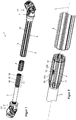
- Fig. 1 shows a schematic perspective illustration of a steering shaft 1 for a motor vehicle.
- the steering shaft 1 has an inner shaft 3, a profile sleeve 4 to be arranged on the inner shaft 3 and an outer shaft 5.
- the inner shaft 3 and the outer shaft 5 are each designed as a hollow shaft. However, it is also conceivable and possible that the inner shaft is designed as a solid shaft.
- the inner shaft 3 and the outer shaft 5 can be manufactured as hollow shafts from a steel or alternatively from aluminum alloys, stainless steel, fiber composite materials or the like.
- the outer shaft 5 and the inner shaft 3 each have a fork 6, 7 at the end, which forms part of a universal joint 61, 71 in order to integrate the steering shaft 1 into a steering line.
- a coupling section for attaching a steering wheel can be provided instead of one of the forks 6, 7, a coupling section for attaching a steering wheel can be provided.
- the outer shaft 5 is in the area of a section 8 in which the inner shaft 3 with the profile sleeve 4 fixed thereon (cf. Fig. 2 ) is inserted, profiled.
- the profile of the outer shaft 5 has grooves 9, which run as radially inwardly protruding sections in the direction of the longitudinal axis L of the outer shaft 5.
- the grooves 9 on an outer circumferential surface 10 of the outer shaft 5 form an internal toothing 11 on an inner circumferential surface 12 of the outer shaft 5 (cf. Fig. 4 ).
- an end section 13 of the inner shaft 3, which is inserted into the outer shaft 5 in an operating state, has an outer toothing 14 which corresponds to the inner toothing 11 of the outer shaft 5.
- the external toothing 14 of the inner shaft 3 is formed with grooves 15 on an outer circumferential surface 16 of the inner shaft 3.
- the profile sleeve 4 is arranged on the external toothing 14 of the inner shaft 3 and corresponds both to the external toothing 14 of the inner shaft 3 and to the internal toothing 11 of the outer shaft 5.
- the profile sleeve 4 is fixed on the inner shaft 3 so that the profile sleeve 4 can move together with the inner shaft 3 relative to the outer shaft 5 therein.
- a sliding seat is provided which allows the length of the steering shaft 1 to be adjusted to a rather low constant force level.
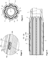
- the profile sleeve 4 has an opening 19 in the region of a section 18 of the profile protruding radially with respect to grooves 17, into which a projection 20 engages, which is arranged on the outer circumferential or peripheral surface 16 of the inner shaft 3 and is formed with two partial projections 20a, 20b which come to rest in the area of opposite ends 19a, 19b of the opening 19 (cf. Fig. 3 ) to fix the profile sleeve 4 on the inner shaft 3, at least in the axial direction.
- a projection 20 engages which is arranged on the outer circumferential or peripheral surface 16 of the inner shaft 3 and is formed with two partial projections 20a, 20b which come to rest in the area of opposite ends 19a, 19b of the opening 19 (cf. Fig. 3 ) to fix the profile sleeve 4 on the inner shaft 3, at least in the axial direction.
- Fig. 4 shows a cross-sectional view through the steering shaft 1 in the area of the opening 19. It can be seen that the profile of the outer shaft 5 corresponds to the profile of the profile sleeve 4 and the profile of the inner shaft 3. For example, the groove 9 of the outer shaft 5 meets one of the grooves 17 of the profile sleeve 4 or the groove 15 of the inner shaft 3. Thus, the inner shaft 3 and the outer shaft 5 are torque-locked with the interposition of the profile sleeve 4.
- Fig. 5 shows a representation of a section of the steering shaft 1 in the area of the profile sleeve 4 fixed on the inner shaft 3 in longitudinal section.
- the partial projections 20a, 20b are each produced as a material bulge, which is shown in FIG Fig. 6 is shown further in detail.
- Radially protruding flange sections 21a, 21b are placed against the ends 19a, 19b of the opening 19.
- the opening 19 is designed as an elongated hole in which opposite longitudinal sides 19c, 19d run parallel to the direction of the longitudinal axis L of the steering shaft 1 or the profile sleeve 4.
- Fig. 6 After the profile sleeve 4 has been pushed onto the inner shaft 3, the formation of the projection 20 with the partial projections 20a, 20b takes place in the area of the opening 19 by means of a tool 22 in order to fix the profile sleeve 4 on the inner shaft 3. Then the inner shaft 3 with the profile sleeve 4 fixed thereon can be inserted into the outer shaft 5 (cf. Fig. 2 ) After insertion, a pull-out safeguard is formed in the outer shaft 5 by means of a plastic deformation, so that the inner shaft 3 can no longer be completely pulled out of the outer shaft 5.
- the tool 22 or the direction of movement of the tool is preferably inclined with respect to the longitudinal axis L.
Landscapes
- Engineering & Computer Science (AREA)
- General Engineering & Computer Science (AREA)
- Mechanical Engineering (AREA)
- Chemical & Material Sciences (AREA)
- Combustion & Propulsion (AREA)
- Transportation (AREA)
- Ocean & Marine Engineering (AREA)
- Steering Controls (AREA)
- Shafts, Cranks, Connecting Bars, And Related Bearings (AREA)
Claims (13)
- Arbre de direction (1) pour un véhicule à moteur, comportant- un arbre intérieur (3) ;- un arbre extérieur (5) ;- une douille profilée (4), qui est disposée sur l'arbre intérieur (3) et fixée sur celui-ci, de telle sorte que l'arbre intérieur (3) soit déplaçable conjointement avec la douille profilée (4) par rapport à l'arbre extérieur (5) dans la direction axiale, l'arbre intérieur (3) et l'arbre extérieur (5) étant accouplés par liaison de transmission de couple par l'intermédiaire de la douille profilée (4),
la douille profilée (4) comprenant une ouverture (19) dans laquelle une saillie (20) disposée sur une surface extérieure de l'arbre intérieur (3) vient en prise de manière à immobiliser la douille profilée (4) dans sa position sur l'arbre intérieur (3) au moins dans la direction axiale, caractérisé en ce que la saillie (20) et l'arbre intérieur (3) sont réalisés sous forme de composant intégré d'une seule pièce. - Arbre de direction (1) selon la revendication 1, caractérisé en ce que l'ouverture (19) est disposée dans une partie de douille profilée centrale dans la direction longitudinale de la douille profilée (4).
- Arbre de direction (1) selon la revendication 1 ou 2, caractérisé en ce que l'ouverture (19) est formée avec un trou oblong.
- Arbre de direction (1) selon au moins l'une des revendications précédentes, caractérisé en ce que des butées de fin de course opposées dans la direction longitudinale de la douille profilée (4) sont formées avec la saillie (20), lesquelles butées sont associées à des extrémités (19a, 19b) de l'ouverture (19) et viennent en contact avec celle-ci.
- Arbre de direction (1) selon au moins l'une des revendications précédentes, caractérisé en ce que la saillie (20) est formée à partir de plusieurs saillies partielles (20a, 20b).
- Arbre de direction (1) selon la revendication 5, caractérisé en ce que les plusieurs saillies partielles (20a, 20b) sont disposées à distance les unes des autres sur la surface extérieure de l'arbre intérieur (3).
- Arbre de direction (1) selon la revendication 5 ou 6, caractérisé en ce que les plusieurs saillies partielles (20a, 20b) sont formées séparément les unes des autres sur la surface extérieure de l'arbre intérieur (3) .
- Arbre de direction (1) selon au moins l'une des revendications précédentes, caractérisé en ce que la saillie (20) est formée au moyen d'un renflement de matière sur la surface extérieure de l'arbre intérieur (3) .
- Arbre de direction (1) selon au moins l'une des revendications précédentes, caractérisé en ce qu'une surface extérieure de la saillie (20) s'appuie au moins dans certaines parties avec complémentarité de forme contre une surface intérieure de l'ouverture (19).
- Arbre de direction (1) selon au moins l'une des revendications précédentes, caractérisé en ce que l'ouverture (19) est disposée au moins dans certaines parties dans la région d'une partie (18) saillante radialement d'un profilage de surface extérieure de la douille profilée (4).
- Arbre de direction (1) selon au moins l'une des revendications précédentes, caractérisé en ce que la saillie (20) traverse complètement l'ouverture (19) dans la direction radiale.
- Arbre de direction (1) selon au moins l'une des revendications précédentes, caractérisé en ce que la saillie (20) comprend une partie de rebord (21a, 21b) orientée radialement.
- Procédé de fabrication d'un arbre de direction (1) pour un véhicule à moteur, le procédé comprenant :- la fourniture d'un arbre intérieur (3) ;- la fourniture d'un arbre extérieur (5) ;- la disposition d'une douille profilée (4) sur l'arbre intérieur (3), la douille profilée (4) comprenant une ouverture (19) ;- la fixation de la douille profilée (4) sur l'arbre intérieur (3), une saillie (20) disposée sur une surface extérieure de l'arbre intérieur (3) et fabriquée en tant que renflement de matière étant en l'occurrence disposée dans l'ouverture (19) de la douille profilée (4) et la douille profilée (4) étant ainsi immobilisée dans sa position sur l'arbre intérieur (3) au moins dans la direction axiale ; et- l'introduction de l'arbre intérieur avec la douille profilée (4) dans l'arbre extérieur (5), de telle sorte que la partie d'extrémité (13) de l'arbre intérieur (3) soit déplaçable conjointement avec la douille profilée (4) dans l'arbre extérieur (5) dans la direction axiale et que la douille profilée (4) soit en l'occurrence disposée entre l'arbre intérieur (3) et l'arbre extérieur (5) .
Priority Applications (1)
| Application Number | Priority Date | Filing Date | Title |
|---|---|---|---|
| PL18735243T PL3645372T3 (pl) | 2017-06-29 | 2018-06-26 | Wał kierowniczy pojazdu mechanicznego i sposób jego wytwarzania |
Applications Claiming Priority (2)
| Application Number | Priority Date | Filing Date | Title |
|---|---|---|---|
| DE102017114534.6A DE102017114534A1 (de) | 2017-06-29 | 2017-06-29 | Lenkwelle für ein Kraftfahrzeug und Verfahren zum Herstellen |
| PCT/EP2018/067120 WO2019002298A1 (fr) | 2017-06-29 | 2018-06-26 | Arbre de direction de véhicule à moteur et son procédé de fabrication |
Publications (2)
| Publication Number | Publication Date |
|---|---|
| EP3645372A1 EP3645372A1 (fr) | 2020-05-06 |
| EP3645372B1 true EP3645372B1 (fr) | 2021-07-28 |
Family
ID=62784134
Family Applications (1)
| Application Number | Title | Priority Date | Filing Date |
|---|---|---|---|
| EP18735243.0A Active EP3645372B1 (fr) | 2017-06-29 | 2018-06-26 | Arbre de direction de véhicule à moteur et son procédé de fabrication |
Country Status (7)
| Country | Link |
|---|---|
| US (1) | US11472467B2 (fr) |
| EP (1) | EP3645372B1 (fr) |
| CN (1) | CN110799406B (fr) |
| DE (1) | DE102017114534A1 (fr) |
| ES (1) | ES2891319T3 (fr) |
| PL (1) | PL3645372T3 (fr) |
| WO (1) | WO2019002298A1 (fr) |
Families Citing this family (2)
| Publication number | Priority date | Publication date | Assignee | Title |
|---|---|---|---|---|
| DE102019205784B3 (de) * | 2019-04-23 | 2020-06-25 | Thyssenkrupp Ag | Längenverstellbare Lenkwelle für ein Kraftfahrzeug und Profilhülse für eine Lenkwelle |
| US11891112B2 (en) * | 2020-06-30 | 2024-02-06 | Steering Solutions Ip Holding Corporation | Intermediate shaft axial retention device |
Citations (1)
| Publication number | Priority date | Publication date | Assignee | Title |
|---|---|---|---|---|
| US20060243089A1 (en) * | 2005-04-28 | 2006-11-02 | Cymbal William D | Telescoping steering shaft |
Family Cites Families (19)
| Publication number | Priority date | Publication date | Assignee | Title |
|---|---|---|---|---|
| US2198654A (en) * | 1938-12-23 | 1940-04-30 | Chrysler Corp | Splined coupling |
| GB2236168B (en) * | 1989-09-21 | 1993-04-07 | Torrington Co | Vehicle steering column |
| US5243874A (en) * | 1992-02-24 | 1993-09-14 | Pittsburgh Tubular Shafting, Inc. | Method and apparatus for telescopically assembling a pair of elongated members |
| US5417614A (en) * | 1994-03-14 | 1995-05-23 | General Motors Corporation | Variable length shaft assembly |
| FR2718803B1 (fr) * | 1994-04-15 | 1996-07-19 | Nadella | Cartouche perfectionnée à roulement à contact oblique et son application à une direction de véhicule. |
| US5655621A (en) * | 1995-06-30 | 1997-08-12 | General Motors Corporation | Motor vehicle power steering gear |
| DE19750005C1 (de) | 1997-11-12 | 1999-04-22 | Supervis Ets | Längenveränderbare Lenkspindel für Lenkvorrichtungen bei Kraftfahrzeugen |
| DE10343685B4 (de) * | 2003-09-20 | 2009-03-19 | Daimler Ag | Fahrzeuglenksäulenanordnung |
| US20060243088A1 (en) * | 2005-04-28 | 2006-11-02 | Delphi Technologies, Inc. | Telescoping steering shaft |
| CN101077712B (zh) * | 2006-09-15 | 2011-01-26 | 奇瑞汽车股份有限公司 | 汽车转向管柱减震装置 |
| US8096036B2 (en) * | 2007-08-29 | 2012-01-17 | Nexteer (Beijing) Technology Co., Ltd. | Method of manufacturing a steering column |
| JP2009191936A (ja) * | 2008-02-14 | 2009-08-27 | Nsk Ltd | 伸縮軸 |
| DE202010017747U1 (de) | 2010-12-21 | 2012-07-10 | Thyssenkrupp Presta Aktiengesellschaft | Gleithülse |
| CN102167073A (zh) * | 2011-03-15 | 2011-08-31 | 四川绵阳三力股份有限公司 | 转向柱及其滑移保持套 |
| JP5429379B2 (ja) * | 2011-05-30 | 2014-02-26 | 日本精工株式会社 | ステアリング装置 |
| CN104228926B (zh) * | 2014-09-25 | 2017-07-28 | 安徽江淮汽车集团股份有限公司 | 转向轴、汽车转向机构及汽车 |
| EP3206811B1 (fr) | 2014-10-17 | 2020-04-22 | thyssenkrupp Presta AG | Procédé de production d'un arbre creux profilé pour arbre de direction télescopique d'un véhicule automobile |
| DE102014017555B4 (de) | 2014-11-28 | 2016-10-13 | Thyssenkrupp Ag | Lenkwelle für ein Kraftfahrzeug |
| DE102015220934B3 (de) | 2015-10-27 | 2016-11-24 | Thyssenkrupp Ag | Lenksäule für ein Kraftfahrzeug und Verfahren zur Herstellung einer Lenksäule |
-
2017
- 2017-06-29 DE DE102017114534.6A patent/DE102017114534A1/de not_active Withdrawn
-
2018
- 2018-06-26 PL PL18735243T patent/PL3645372T3/pl unknown
- 2018-06-26 US US16/621,162 patent/US11472467B2/en active Active
- 2018-06-26 CN CN201880043660.4A patent/CN110799406B/zh active Active
- 2018-06-26 ES ES18735243T patent/ES2891319T3/es active Active
- 2018-06-26 EP EP18735243.0A patent/EP3645372B1/fr active Active
- 2018-06-26 WO PCT/EP2018/067120 patent/WO2019002298A1/fr not_active Ceased
Patent Citations (1)
| Publication number | Priority date | Publication date | Assignee | Title |
|---|---|---|---|---|
| US20060243089A1 (en) * | 2005-04-28 | 2006-11-02 | Cymbal William D | Telescoping steering shaft |
Also Published As
| Publication number | Publication date |
|---|---|
| DE102017114534A1 (de) | 2019-01-03 |
| US20200122769A1 (en) | 2020-04-23 |
| EP3645372A1 (fr) | 2020-05-06 |
| ES2891319T3 (es) | 2022-01-27 |
| US11472467B2 (en) | 2022-10-18 |
| CN110799406A (zh) | 2020-02-14 |
| WO2019002298A1 (fr) | 2019-01-03 |
| CN110799406B (zh) | 2022-10-14 |
| PL3645372T3 (pl) | 2021-12-20 |
Similar Documents
| Publication | Publication Date | Title |
|---|---|---|
| DE10158545B4 (de) | Längsverschiebeeinheit mit hohlem Profilzapfen | |
| EP3577012B1 (fr) | Arbre de direction réglable en longueur pour un véhicule automobile et douille profilée pour un arbre de direction | |
| EP0278292B1 (fr) | Arbre creux et son procédé de fabrication | |
| DE102011008396A1 (de) | Kupplung zum dämpfenden Verbinden zweier Wellenabschnitte insbesondere einer Lenkwelle, sowie Lenkwelle und Verfahren zu Herstellung einer entsprechenden Kupplung | |
| EP3497343B1 (fr) | Arbre de direction d'un véhicule automobile | |
| WO2013020683A1 (fr) | Dispositif de direction | |
| EP2012036A2 (fr) | Arrêt | |
| WO2017041803A1 (fr) | Élément de pression d'une boîte de vitesses de véhicule et unité de syncrhonisation | |
| EP3645372B1 (fr) | Arbre de direction de véhicule à moteur et son procédé de fabrication | |
| DE102016205977A1 (de) | Baugruppe für eine Synchronisationsvorrichtung sowie Synchronisationsvorrichtung mit der Baugruppe | |
| EP3277978B1 (fr) | Joint de chaîne pourvu d'un élément de sûreté | |
| DE10158544C2 (de) | Längsverschiebeeinheit aus Material gleicher Wandstärke | |
| EP3959115B1 (fr) | Arbre de direction réglable en longueur pour un véhicule à moteur et douille profilée pour un arbre de direction | |
| DE19929639B4 (de) | Welle-Nabe-Verbindung mit umgeformten Anschlagschrägen in Wellenverzahnung | |
| DE102014210139A1 (de) | Bauteilverbindung mit verpresstem Bolzenelement | |
| WO2013056822A1 (fr) | Dispositif d'assemblage et procédé de fabrication dudit dispositif | |
| WO2011160240A1 (fr) | Corps d'arbre comprenant un segment à contour externe moleté longitudinalement | |
| EP1208313B1 (fr) | Corps de synchroniseur forme d'une piece moulee en tole | |
| EP1146242B1 (fr) | Corps de sychroniseur pour ensemble de sychronisation en tôle | |
| EP3098137B1 (fr) | Arbre a longueur variable pour un dispositif de direction d'un vehicule et dispositif de direction de vehicule | |
| DE4233406B4 (de) | Kupplungsscheibe mit einer Kunststoffnabe | |
| DE19845148A1 (de) | Anlasser | |
| EP3877105A1 (fr) | Unité de fixation | |
| EP3181931B1 (fr) | Équilibrage des longueurs pour un arbre de transmission | |
| EP3714177B1 (fr) | Dispositif avec une connexion ferme contre la rotation |
Legal Events
| Date | Code | Title | Description |
|---|---|---|---|
| STAA | Information on the status of an ep patent application or granted ep patent |
Free format text: STATUS: UNKNOWN |
|
| STAA | Information on the status of an ep patent application or granted ep patent |
Free format text: STATUS: THE INTERNATIONAL PUBLICATION HAS BEEN MADE |
|
| PUAI | Public reference made under article 153(3) epc to a published international application that has entered the european phase |
Free format text: ORIGINAL CODE: 0009012 |
|
| STAA | Information on the status of an ep patent application or granted ep patent |
Free format text: STATUS: REQUEST FOR EXAMINATION WAS MADE |
|
| 17P | Request for examination filed |
Effective date: 20200129 |
|
| AK | Designated contracting states |
Kind code of ref document: A1 Designated state(s): AL AT BE BG CH CY CZ DE DK EE ES FI FR GB GR HR HU IE IS IT LI LT LU LV MC MK MT NL NO PL PT RO RS SE SI SK SM TR |
|
| AX | Request for extension of the european patent |
Extension state: BA ME |
|
| STAA | Information on the status of an ep patent application or granted ep patent |
Free format text: STATUS: EXAMINATION IS IN PROGRESS |
|
| 17Q | First examination report despatched |
Effective date: 20200609 |
|
| DAV | Request for validation of the european patent (deleted) | ||
| DAX | Request for extension of the european patent (deleted) | ||
| GRAP | Despatch of communication of intention to grant a patent |
Free format text: ORIGINAL CODE: EPIDOSNIGR1 |
|
| STAA | Information on the status of an ep patent application or granted ep patent |
Free format text: STATUS: GRANT OF PATENT IS INTENDED |
|
| INTG | Intention to grant announced |
Effective date: 20210226 |
|
| GRAS | Grant fee paid |
Free format text: ORIGINAL CODE: EPIDOSNIGR3 |
|
| RIN1 | Information on inventor provided before grant (corrected) |
Inventor name: DUROT, JANICK Inventor name: BREUER, MARIUS |
|
| GRAA | (expected) grant |
Free format text: ORIGINAL CODE: 0009210 |
|
| STAA | Information on the status of an ep patent application or granted ep patent |
Free format text: STATUS: THE PATENT HAS BEEN GRANTED |
|
| AK | Designated contracting states |
Kind code of ref document: B1 Designated state(s): AL AT BE BG CH CY CZ DE DK EE ES FI FR GB GR HR HU IE IS IT LI LT LU LV MC MK MT NL NO PL PT RO RS SE SI SK SM TR |
|
| REG | Reference to a national code |
Ref country code: GB Ref legal event code: FG4D Free format text: NOT ENGLISH |
|
| REG | Reference to a national code |
Ref country code: CH Ref legal event code: EP |
|
| REG | Reference to a national code |
Ref country code: DE Ref legal event code: R096 Ref document number: 502018006344 Country of ref document: DE |
|
| REG | Reference to a national code |
Ref country code: AT Ref legal event code: REF Ref document number: 1414509 Country of ref document: AT Kind code of ref document: T Effective date: 20210815 |
|
| REG | Reference to a national code |
Ref country code: IE Ref legal event code: FG4D Free format text: LANGUAGE OF EP DOCUMENT: GERMAN |
|
| REG | Reference to a national code |
Ref country code: LT Ref legal event code: MG9D |
|
| REG | Reference to a national code |
Ref country code: NL Ref legal event code: MP Effective date: 20210728 |
|
| REG | Reference to a national code |
Ref country code: ES Ref legal event code: FG2A Ref document number: 2891319 Country of ref document: ES Kind code of ref document: T3 Effective date: 20220127 |
|
| PG25 | Lapsed in a contracting state [announced via postgrant information from national office to epo] |
Ref country code: RS Free format text: LAPSE BECAUSE OF FAILURE TO SUBMIT A TRANSLATION OF THE DESCRIPTION OR TO PAY THE FEE WITHIN THE PRESCRIBED TIME-LIMIT Effective date: 20210728 Ref country code: SE Free format text: LAPSE BECAUSE OF FAILURE TO SUBMIT A TRANSLATION OF THE DESCRIPTION OR TO PAY THE FEE WITHIN THE PRESCRIBED TIME-LIMIT Effective date: 20210728 Ref country code: FI Free format text: LAPSE BECAUSE OF FAILURE TO SUBMIT A TRANSLATION OF THE DESCRIPTION OR TO PAY THE FEE WITHIN THE PRESCRIBED TIME-LIMIT Effective date: 20210728 Ref country code: HR Free format text: LAPSE BECAUSE OF FAILURE TO SUBMIT A TRANSLATION OF THE DESCRIPTION OR TO PAY THE FEE WITHIN THE PRESCRIBED TIME-LIMIT Effective date: 20210728 Ref country code: PT Free format text: LAPSE BECAUSE OF FAILURE TO SUBMIT A TRANSLATION OF THE DESCRIPTION OR TO PAY THE FEE WITHIN THE PRESCRIBED TIME-LIMIT Effective date: 20211129 Ref country code: NO Free format text: LAPSE BECAUSE OF FAILURE TO SUBMIT A TRANSLATION OF THE DESCRIPTION OR TO PAY THE FEE WITHIN THE PRESCRIBED TIME-LIMIT Effective date: 20211028 Ref country code: NL Free format text: LAPSE BECAUSE OF FAILURE TO SUBMIT A TRANSLATION OF THE DESCRIPTION OR TO PAY THE FEE WITHIN THE PRESCRIBED TIME-LIMIT Effective date: 20210728 Ref country code: BG Free format text: LAPSE BECAUSE OF FAILURE TO SUBMIT A TRANSLATION OF THE DESCRIPTION OR TO PAY THE FEE WITHIN THE PRESCRIBED TIME-LIMIT Effective date: 20211028 Ref country code: LT Free format text: LAPSE BECAUSE OF FAILURE TO SUBMIT A TRANSLATION OF THE DESCRIPTION OR TO PAY THE FEE WITHIN THE PRESCRIBED TIME-LIMIT Effective date: 20210728 |
|
| PG25 | Lapsed in a contracting state [announced via postgrant information from national office to epo] |
Ref country code: LV Free format text: LAPSE BECAUSE OF FAILURE TO SUBMIT A TRANSLATION OF THE DESCRIPTION OR TO PAY THE FEE WITHIN THE PRESCRIBED TIME-LIMIT Effective date: 20210728 Ref country code: GR Free format text: LAPSE BECAUSE OF FAILURE TO SUBMIT A TRANSLATION OF THE DESCRIPTION OR TO PAY THE FEE WITHIN THE PRESCRIBED TIME-LIMIT Effective date: 20211029 |
|
| PG25 | Lapsed in a contracting state [announced via postgrant information from national office to epo] |
Ref country code: DK Free format text: LAPSE BECAUSE OF FAILURE TO SUBMIT A TRANSLATION OF THE DESCRIPTION OR TO PAY THE FEE WITHIN THE PRESCRIBED TIME-LIMIT Effective date: 20210728 |
|
| REG | Reference to a national code |
Ref country code: DE Ref legal event code: R097 Ref document number: 502018006344 Country of ref document: DE |
|
| PG25 | Lapsed in a contracting state [announced via postgrant information from national office to epo] |
Ref country code: SM Free format text: LAPSE BECAUSE OF FAILURE TO SUBMIT A TRANSLATION OF THE DESCRIPTION OR TO PAY THE FEE WITHIN THE PRESCRIBED TIME-LIMIT Effective date: 20210728 Ref country code: SK Free format text: LAPSE BECAUSE OF FAILURE TO SUBMIT A TRANSLATION OF THE DESCRIPTION OR TO PAY THE FEE WITHIN THE PRESCRIBED TIME-LIMIT Effective date: 20210728 Ref country code: RO Free format text: LAPSE BECAUSE OF FAILURE TO SUBMIT A TRANSLATION OF THE DESCRIPTION OR TO PAY THE FEE WITHIN THE PRESCRIBED TIME-LIMIT Effective date: 20210728 Ref country code: EE Free format text: LAPSE BECAUSE OF FAILURE TO SUBMIT A TRANSLATION OF THE DESCRIPTION OR TO PAY THE FEE WITHIN THE PRESCRIBED TIME-LIMIT Effective date: 20210728 Ref country code: AL Free format text: LAPSE BECAUSE OF FAILURE TO SUBMIT A TRANSLATION OF THE DESCRIPTION OR TO PAY THE FEE WITHIN THE PRESCRIBED TIME-LIMIT Effective date: 20210728 |
|
| PLBE | No opposition filed within time limit |
Free format text: ORIGINAL CODE: 0009261 |
|
| STAA | Information on the status of an ep patent application or granted ep patent |
Free format text: STATUS: NO OPPOSITION FILED WITHIN TIME LIMIT |
|
| 26N | No opposition filed |
Effective date: 20220429 |
|
| REG | Reference to a national code |
Ref country code: DE Ref legal event code: R084 Ref document number: 502018006344 Country of ref document: DE |
|
| PG25 | Lapsed in a contracting state [announced via postgrant information from national office to epo] |
Ref country code: MC Free format text: LAPSE BECAUSE OF FAILURE TO SUBMIT A TRANSLATION OF THE DESCRIPTION OR TO PAY THE FEE WITHIN THE PRESCRIBED TIME-LIMIT Effective date: 20210728 |
|
| REG | Reference to a national code |
Ref country code: CH Ref legal event code: PL |
|
| REG | Reference to a national code |
Ref country code: BE Ref legal event code: MM Effective date: 20220630 |
|
| PG25 | Lapsed in a contracting state [announced via postgrant information from national office to epo] |
Ref country code: IE Free format text: LAPSE BECAUSE OF NON-PAYMENT OF DUE FEES Effective date: 20220626 Ref country code: CH Free format text: LAPSE BECAUSE OF NON-PAYMENT OF DUE FEES Effective date: 20220630 Ref country code: LU Free format text: LAPSE BECAUSE OF NON-PAYMENT OF DUE FEES Effective date: 20220626 Ref country code: LI Free format text: LAPSE BECAUSE OF NON-PAYMENT OF DUE FEES Effective date: 20220630 |
|
| PG25 | Lapsed in a contracting state [announced via postgrant information from national office to epo] |
Ref country code: BE Free format text: LAPSE BECAUSE OF NON-PAYMENT OF DUE FEES Effective date: 20220630 |
|
| PGFP | Annual fee paid to national office [announced via postgrant information from national office to epo] |
Ref country code: FR Payment date: 20230628 Year of fee payment: 6 Ref country code: CZ Payment date: 20230619 Year of fee payment: 6 |
|
| PGFP | Annual fee paid to national office [announced via postgrant information from national office to epo] |
Ref country code: PL Payment date: 20230619 Year of fee payment: 6 |
|
| PGFP | Annual fee paid to national office [announced via postgrant information from national office to epo] |
Ref country code: IT Payment date: 20230623 Year of fee payment: 6 Ref country code: GB Payment date: 20230622 Year of fee payment: 6 Ref country code: ES Payment date: 20230830 Year of fee payment: 6 |
|
| PG25 | Lapsed in a contracting state [announced via postgrant information from national office to epo] |
Ref country code: MK Free format text: LAPSE BECAUSE OF FAILURE TO SUBMIT A TRANSLATION OF THE DESCRIPTION OR TO PAY THE FEE WITHIN THE PRESCRIBED TIME-LIMIT Effective date: 20210728 Ref country code: CY Free format text: LAPSE BECAUSE OF FAILURE TO SUBMIT A TRANSLATION OF THE DESCRIPTION OR TO PAY THE FEE WITHIN THE PRESCRIBED TIME-LIMIT Effective date: 20210728 |
|
| PG25 | Lapsed in a contracting state [announced via postgrant information from national office to epo] |
Ref country code: HU Free format text: LAPSE BECAUSE OF FAILURE TO SUBMIT A TRANSLATION OF THE DESCRIPTION OR TO PAY THE FEE WITHIN THE PRESCRIBED TIME-LIMIT; INVALID AB INITIO Effective date: 20180626 |
|
| REG | Reference to a national code |
Ref country code: AT Ref legal event code: MM01 Ref document number: 1414509 Country of ref document: AT Kind code of ref document: T Effective date: 20230626 |
|
| PG25 | Lapsed in a contracting state [announced via postgrant information from national office to epo] |
Ref country code: MT Free format text: LAPSE BECAUSE OF FAILURE TO SUBMIT A TRANSLATION OF THE DESCRIPTION OR TO PAY THE FEE WITHIN THE PRESCRIBED TIME-LIMIT Effective date: 20210728 |
|
| PG25 | Lapsed in a contracting state [announced via postgrant information from national office to epo] |
Ref country code: AT Free format text: LAPSE BECAUSE OF NON-PAYMENT OF DUE FEES Effective date: 20230626 |
|
| PG25 | Lapsed in a contracting state [announced via postgrant information from national office to epo] |
Ref country code: AT Free format text: LAPSE BECAUSE OF NON-PAYMENT OF DUE FEES Effective date: 20230626 |
|
| PG25 | Lapsed in a contracting state [announced via postgrant information from national office to epo] |
Ref country code: CZ Free format text: LAPSE BECAUSE OF NON-PAYMENT OF DUE FEES Effective date: 20240626 |
|
| PG25 | Lapsed in a contracting state [announced via postgrant information from national office to epo] |
Ref country code: CZ Free format text: LAPSE BECAUSE OF NON-PAYMENT OF DUE FEES Effective date: 20240626 |
|
| GBPC | Gb: european patent ceased through non-payment of renewal fee |
Effective date: 20240626 |
|
| PG25 | Lapsed in a contracting state [announced via postgrant information from national office to epo] |
Ref country code: FR Free format text: LAPSE BECAUSE OF NON-PAYMENT OF DUE FEES Effective date: 20240630 |
|
| PG25 | Lapsed in a contracting state [announced via postgrant information from national office to epo] |
Ref country code: IT Free format text: LAPSE BECAUSE OF NON-PAYMENT OF DUE FEES Effective date: 20240626 Ref country code: GB Free format text: LAPSE BECAUSE OF NON-PAYMENT OF DUE FEES Effective date: 20240626 |
|
| PGFP | Annual fee paid to national office [announced via postgrant information from national office to epo] |
Ref country code: DE Payment date: 20250618 Year of fee payment: 8 |
|
| REG | Reference to a national code |
Ref country code: ES Ref legal event code: FD2A Effective date: 20250731 |
|
| PG25 | Lapsed in a contracting state [announced via postgrant information from national office to epo] |
Ref country code: ES Free format text: LAPSE BECAUSE OF NON-PAYMENT OF DUE FEES Effective date: 20240627 |
|
| PG25 | Lapsed in a contracting state [announced via postgrant information from national office to epo] |
Ref country code: PL Free format text: LAPSE BECAUSE OF NON-PAYMENT OF DUE FEES Effective date: 20240626 |
|
| PG25 | Lapsed in a contracting state [announced via postgrant information from national office to epo] |
Ref country code: TR Free format text: LAPSE BECAUSE OF FAILURE TO SUBMIT A TRANSLATION OF THE DESCRIPTION OR TO PAY THE FEE WITHIN THE PRESCRIBED TIME-LIMIT Effective date: 20210728 |
|
| PGFP | Annual fee paid to national office [announced via postgrant information from national office to epo] |
Ref country code: AT Payment date: 20260410 Year of fee payment: 5 |