EP3645376B1 - Châssis de véhicule agricole de largeur réglable et véhicule agricole - Google Patents
Châssis de véhicule agricole de largeur réglable et véhicule agricole Download PDFInfo
- Publication number
- EP3645376B1 EP3645376B1 EP19740643.2A EP19740643A EP3645376B1 EP 3645376 B1 EP3645376 B1 EP 3645376B1 EP 19740643 A EP19740643 A EP 19740643A EP 3645376 B1 EP3645376 B1 EP 3645376B1
- Authority
- EP
- European Patent Office
- Prior art keywords
- compass
- chassis
- angle
- frame
- adjusting
- Prior art date
- Legal status (The legal status is an assumption and is not a legal conclusion. Google has not performed a legal analysis and makes no representation as to the accuracy of the status listed.)
- Not-in-force
Links
Images




Classifications
-
- B—PERFORMING OPERATIONS; TRANSPORTING
- B62—LAND VEHICLES FOR TRAVELLING OTHERWISE THAN ON RAILS
- B62D—MOTOR VEHICLES; TRAILERS
- B62D49/00—Tractors
- B62D49/06—Tractors adapted for multi-purpose use
- B62D49/0678—Tractors of variable track width or wheel base
-
- B—PERFORMING OPERATIONS; TRANSPORTING
- B62—LAND VEHICLES FOR TRAVELLING OTHERWISE THAN ON RAILS
- B62D—MOTOR VEHICLES; TRAILERS
- B62D49/00—Tractors
- B62D49/06—Tractors adapted for multi-purpose use
- B62D49/0607—Straddle tractors, used for instance above vine stocks, rows of bushes, or the like
Definitions
- the invention relates to an agricultural vehicle frame whose width is adjustable and to an agricultural vehicle provided with such a frame.
- the documents FR329501A and WO2015197173A1 describe similar devices.
- Adjusting the width of an agricultural vehicle frame makes it possible to adapt the agricultural vehicle to different uses, depending on the dimensions of the plantations for which the vehicle is used and / or the agricultural treatments to be carried out.
- Agricultural vehicles of the straddle-width and / or adjustable track type are already known by virtue of telescopic cross members and / or jacks connecting two lateral half-frames.
- Such telescopic sleepers require particularly complex and expensive translational guide means, of the type of those for telescopic arms for construction machinery, so as to avoid the presence of any untimely clearances between the two half-frames. It should be noted in this regard that the wear of these guide means results in the appearance or increase of bending clearances in the telescopic sleepers, such clearances also having the consequence of increasing wear, stresses, etc. shocks and risks of rupture.
- each telescopic cross member being formed of an internal bar sliding in an external bar, the amplitude of variation of the frame width is limited by the length of the internal bar, and the internal bar is limited by the length of the outer bar, except accepting that the inner bar extends projecting beyond the outer end of the outer bar, to the detriment of the overall width of the chassis and the vehicle.
- the overall width of an agricultural vehicle constitutes a very important parameter in the use of the agricultural vehicle, in particular in the position of minimum width.
- the increase in width of the frame is at most of the order of 0.6 m, i.e. a maximum width of 1.4 m.
- Such telescopic sleepers are not very compatible with agricultural vehicles which are most often used in severe environmental conditions, in the presence of projections of mud, stones, sand, earth, etc., subject to corrosion and chemical attack. .
- Such conditions in fact present the risk of premature aging of the guide means, or of the introduction of solid particles between the bars of the telescopic sleepers, which may lead to jamming or premature wear.
- the protections that can be made to protect the guide means from the outside, which can be formed by bellows, seals or membranes, are themselves subject to wear and aging and must be subject to periodic checks and maintenance. maintenance.
- telescopic cross members are not optimal from the point of view of the general rigidity and the resistance to deformation of the frame.
- the invention therefore aims to overcome these drawbacks.
- the invention also aims to provide an agricultural vehicle frame having a large amplitude of variation in width, without compromising the overall width of the vehicle, in particular its minimum size in the minimum width position.
- the invention also aims in this respect to provide an agricultural vehicle chassis providing perfect safety of use.
- the invention also aims to provide an agricultural vehicle chassis of adjustable width and compatible with its use in all agricultural environments, including the most severe ones, having a long service life and not requiring regular specific checking and checking operations. maintenance.
- It also aims to provide an agricultural vehicle chassis allowing the production of a multipurpose agricultural vehicle, and the simple and rapid installation of various agricultural treatment devices allowing the use of the agricultural vehicle for the various agricultural treatments to be carried out during seasons.
- the invention also aims to provide an agricultural vehicle having the same advantages.
- a frame and an agricultural vehicle according to the invention define a main axis of advance, called the longitudinal axis, corresponding to a privileged axis of advance of the agricultural vehicle when it is performing agricultural work.
- This longitudinal axis is also in general the axis along which the chassis according to the invention has the largest dimension overall.
- the width of a frame according to the invention is a dimension of the latter along a horizontal axis orthogonal to said longitudinal axis.
- a forward orientation and a rearward orientation can be defined along said longitudinal axis, either that the agricultural vehicle according to the invention has a privileged direction, called forward direction, of advancement along said longitudinal axis; or on the contrary that the agricultural vehicle according to the invention is adapted to be able to move in both directions along said longitudinal axis, in which case any one of the longitudinal ends of the frame is designated as the front end, the other opposite longitudinal end being designated rear end.
- the adjustment of the distance separating the two side half-frames involves rotational movements according to pivots which have substantially constant mechanical characteristics and experience similar mechanical stresses over the full range of frame width variations.
- pivots are also particularly simple and economical, of low weight and bulk, and of mechanical characteristics which have been perfectly mastered for many years. They are much better compatible with harsh agricultural environments than translational guides. They have a long lifespan, and do not require specific regular checking and maintenance operations.
- an adjustment in width by means of a compass makes it possible to obtain a large variation in width dimensions, which can typically be between 0.5 m and 3 m (in particular between 0.8 m and 2 m), without compromising the overall width of the chassis, in particular for the minimum value of the width.
- the invention is applicable in certain embodiments in which the two side half-frames are not strictly identical to each other, or even are different in their shapes and dimensions. However, in certain advantageous embodiments according to the invention, the two side half-frames have the same shapes and dimensions.
- each compass also constitutes a rigid mechanical connection (but adjustable in width) between the two side half-frames.
- the invention makes it possible in particular to limit or even eliminate any guiding in translation for the width adjustment of the frame. None prevents however, to provide certain parts guided in translation as necessary.
- the width adjustment can be obtained mainly by each compass of the adjustment device, and by the device for adjusting the corresponding compass angle, so that any parts guided in translation do not support not most of the forces imparted between the two side half-frames.
- guide in rotation can be actuated by an actuator associated with a transmission, this actuator and this transmission being able to be chosen so as to optimize their own characteristics in terms of power and travel, so simple, economical, light and space-saving.
- a frame according to the invention also has the advantage of greatly simplifying the mechanical connection between the two side half-frames and the actuation of the adjustment device, which can be simply motorized.
- said adjustment device which constitutes the mechanical connection between the two side half-frames, comprises at least one actuator (this term designating any device delivering mechanical energy to from an energy of a nature other than mechanical: cylinder, motor, etc.) of at least one device for adjusting the compass angle of at least one compass.
- said adjustment device comprises, as an actuator exclusively at least one such actuator, of at least one device for adjusting the compass angle of at least one. compass.
- said adjustment device comprises, as an actuator exclusively at least one such actuator, of at least one device for adjusting the compass angle of at least one. compass.
- the adjustment device comprises a strengthening cylinder for each compass so as to improve the rigidity of the frame.
- said pivots of the central articulation and of the lateral articulations of each compass are non-sliding pivots (that is to say without the possibility of translation parallel to the pivot axis) and have axes of pivots which are parallel to each other.
- said central articulation of at least one compass - in particular of each compass - comprises a non-sliding pivot with a vertical axis (that is to say orthogonal to the running surface of the wheels of the vehicle which is assumed to be horizontal) -in particular is formed of a non-sliding pivot with a vertical axis-.
- each lateral articulation of at least one compass - in particular of each compass - comprises a non-sliding pivot with a vertical axis - in particular is formed of a non-sliding pivot with a vertical axis.
- a chassis according to the invention comprising a plurality of compasses exhibits improved rigidity thanks to a flying buttress effect resulting from the compasses.
- said central articulation of at least one compass - in particular of each compass - comprises a non-sliding pivot with a non-vertical axis (that is to say not orthogonal to the plane. bearing of the wheels of the vehicle which is assumed to be horizontal) - in particular that said central articulation is formed of a non-sliding pivot with a non-vertical axis -.
- each compass - each include a non-sliding pivot with a non-vertical axis - in particular that each lateral articulation is formed of a non-sliding pivot with non-vertical axis. vertical-.
- Such a compass then extends in a non-horizontal plane and can be inclined for example upwards or downwards with respect to the side half-frames.
- the pivots of the central and lateral joints of at least one compass - in particular of each compass - have horizontal pivot axes.
- Such a compass whose arms are straight beams then extends in a vertical plane.
- each compass of a frame according to the invention can be the subject of various variant embodiments. Any device making it possible to define a distance between two ends (one corresponding to the central articulation, the other to a lateral articulation) can be used as a rigid arm in a compass of a frame according to the invention.
- these arms are formed of straight beams, for example of metal sections; However, nothing prevents the provision of arms having shapes distinct from a straight line, for example curved in a horizontal plane and / or in a vertical plane and / or in any another plane, or in the form of broken lines ...
- At least one rigid arm - in particular the rigid arms of at least one compass - in particular of each compass - of adjustable length for example in the form of a telescopic arms.
- Preferably the two rigid arms of at least one and the same compass - in particular of each compass - have the same length.
- the device for adjusting the compass angle can be the subject of various structural variants since it allows effective adjustment of the compass angle value and its locking after adjustment.
- a device for adjusting the compass angle can cooperate with the central articulation and / or at least one lateral articulation and / or each lateral articulation of the compass.
- the device for adjusting the angle of the compass of at least one compass - in particular of each compass - is adapted to allow angular adjustment of the central articulation and a locking of said central articulation after adjustment. .
- each compass angle of each compass always remains oriented in the same direction with respect to said longitudinal axis, that is to say either towards the front or towards the rear, whatever the value of the frame width.
- the device for adjusting the compass angle of at least one compass - in particular of each compass - is adapted to impose a value of the compass angle greater than 0 ° and less than 180 °, values excluded.
- the two arms of the compass always form a non-zero angle between them, which in practice confers great general rigidity on the frame according to the invention and greatly facilitates the actuation of the adjustment device.
- the two arms cannot be aligned with respect to each other, any risk of inadvertent blocking is avoided.
- the adjustment device is suitable for imposing a compass angle value greater than or equal to 20 °, more particularly greater than or equal to 30 °, even more particularly greater than or equal to 45 °.
- the adjustment device is adapted to impose a compass angle value less than or equal to 160 °, more particularly less than or equal to 150 °, even more particularly less than or equal to 145 ° .
- Said device for adjusting a frame according to the invention may include a number of calipers which may vary, depending on the needs and the applications.
- said adjustment device comprises a single compass, for example placed in the center of the frame along said longitudinal axis.
- each lateral articulation is provided with a locking device making it possible to lock it in position after adjusting the width of the frame, that is to say after adjusting the compass angle, so that the position angular angle of each lateral half-frame with respect to each compass arm to which it is articulated is kept fixed, the orientation of each lateral half-frame with respect to each other and with respect to said longitudinal axis remaining the same as it is regardless of the width of the frame.
- said adjustment device comprises at least two compasses.
- said adjustment device advantageously comprises a plurality of calipers uniformly distributed along said longitudinal axis, oriented in the same direction and / or in opposite directions.
- said adjustment device may include at least one front compass, at least one central compass and at least one rear compass.
- said adjustment device comprises a plurality of calipers and a control unit for the device for adjusting the angle of the compass of the various compasses, this control unit being adapted to maintain the same relative orientation of the two halves. side frames with respect to each other and with respect to said longitudinal axis.
- the two side half-frames are kept generally parallel to each other and to the axis longitudinal.
- said control unit is also suitable for controlling the device for adjusting the compass angle of the various compasses in synchronism.
- said adjustment device comprises at least one front compass, the apex of the compass angle of which is oriented forwards and at least one rear caliper, the apex of the angle of which is compass is oriented rearward.
- said adjustment device comprises a front compass and a rear compass.
- said control unit is adapted to control the device for adjusting the compass angle of the front and rear compass.
- said adjustment device comprises two compasses with opposing compass angles oriented outwardly with respect to each other, that is to say a front compass at compass angle with the top facing forward and a rear compass angle compass with the top facing rear.
- This arrangement makes it possible, on the one hand, to provide an optimal central space for accommodating agricultural treatment devices (in particular instruments, apparatus or tools), and, on the other hand, confers optimum inertia and rigidity on the frame by a flying buttress, in particular in the case where the pivot axes of the central and lateral joints of the compasses are vertical as indicated above.
- the different calipers have the same dimensions and, in any position for adjusting the width of the frame, the same compass angle values. .
- the front and rear calipers have the same dimensions and the same compass angles. In this way, it suffices that the variations of the compass angle controlled by the control unit are the same for the different compasses to ensure that the relative orientation of the two side half-frames is maintained with respect to one another. the other, in particular their parallelism, whatever the width of the chassis.
- Such an agricultural vehicle chassis provides many advantages: it is compatible with a large number of agricultural processing devices (in particular instruments, apparatus or tools) which can be easily installed and rigidly fixed in the center of the chassis, between the two side members and / or in front of the front pillars and / or behind the rear pillars, both in the immediate vicinity of the ground and in height; it has great rigidity for a reduced weight; it allows the easy mounting of wheels in front of the front uprights and behind the rear uprights; it makes it possible to easily produce a self-propelled agricultural vehicle controlled remotely, or even a robot, as well as a self-propelled agricultural vehicle driven by a human operator; it makes it possible to receive at least one seat intended to receive a human operator (pilot and / or agricultural treatment operator) whose location can be the subject of many variations depending on the use of the agricultural vehicle (for example nearby soil for market gardening or in height for the treatment of shrubs) ...
- agricultural processing devices in particular instruments, apparatus or tools
- This combination of features also provides many advantages.
- it makes it possible to obtain, in a simple and economical manner, a chassis whose weight / rigidity ratio is particularly low; exhibiting great versatility and making it possible to accept a very large number of different agricultural treatment instruments and / or apparatus and / or tools; whose width adjustment is particularly simple and reliable and can be carried out over a wide range of width variation; the mechanical characteristics of which remain substantially the same, in particular without play and of great rigidity, whatever the width to which it is adjusted; who is compatible with all agricultural environments, including the most severe; which has a long service life and requires little maintenance; which allows the production of various types of agricultural vehicles: self-propelled vehicles piloted by an on-board pilot, remote-controlled self-propelled vehicles, in particular remote-controlled, robotic, etc.
- the front and rear uprights may also extend downwardly from the corresponding ends of the side member, the side half frame having a general shape of H.
- the front and rear uprights extend exclusively upwards from the side member, the side half-frame having the general shape of a U.
- each compass is articulated between upper ends of said uprights. In this way, the space between the two side half-frames is left free over the entire height of the uprights.
- each side half-frame is formed of a rigid metal structure of beams and plates assembled rigidly, in particular by bolting and / or welding and / or riveting.
- each side half-frame is advantageously provided with pairs of perforated plates, the plates of each pair of perforated plates being parallel and spaced from each other by an identical distance for all the pairs of perforated plates of this so as to allow the insertion and assembly by bolting of at least one mounting flange of an agricultural treatment device between the two plates of each pair of perforated plates.
- the two plates of each pair of perforated plates are bolted to one another and / or on either side of at least one beam of the lateral half-frame.
- each side half-frame is provided with pairs of perforated longitudinal vertical plates having transverse horizontal holes, the plates of each pair of longitudinal vertical plates being spaced transversely from one another by an identical distance for all the pairs of perforated plates in this way to allow the insertion and the assembly by bolting, between the two plates of each pair, of at least one mounting flange of an agricultural treatment device.
- the two plates of each pair of longitudinal vertical perforated plates are bolted to one another and / or to one side and the other of at least one beam - in particular of a spar and / or an upright of the side half-frame.
- Such a particularly simple structure surprisingly exhibits very high mechanical performance (in particular a low weight / rigidity and strength ratio) and great versatility with regard to the installation of the various agricultural treatment devices.
- such agricultural treatment devices of various kinds can be fixed between the lower side members and between the uprights and / or at the front of the front uprights and / or at the rear of the rear uprights.
- a frame according to the invention further comprises at least one plate extending between the two side half-frames and adapted to be able to support equipment of the agricultural vehicle: seat and / or engine and / or tank and / or hydraulic power station and / or other.
- a plate has a width corresponding to the minimum width of the frame according to the invention, and is connected to each side half-frame by cross members connected so as to be able to slide relative to the plate during the width adjustment. of the chassis.
- a frame according to the invention comprises at least one upper plate arranged on the frame at a height level greater than that of each compass of said adjustment device.
- a chassis according to the invention comprises a rear upper plate extending in cantilever towards the rear above the upper ends of the rear uprights.
- a rear upper plate can be carried by a rear upper extension. plates bolted to one side and the other of each rear pillar and / or by upper rear side members attached to the rear ends of the rear pillars.
- the invention extends to an agricultural vehicle — in particular a self-propelled vehicle — comprising a chassis according to the invention.
- An agricultural vehicle advantageously comprises wheels mounted in the lower part of the uprights of the frame.
- wheels mounted in the lower part towards the front of each front upright and a rear wheel mounted in the lower part towards the rear of each rear upright.
- each wheel is directional and independent, that is to say can be oriented independently of the other wheels.
- each wheel is orientable relative to the longitudinal axis according to an orientation angle which may be between 0 ° and 90 °.
- an orientation angle of 0 ° for each of the wheels the vehicle moves along the longitudinal axis.
- an orientation angle of 90 ° for each of the wheels the vehicle moves orthogonally to the longitudinal axis.
- the width adjustment of the frame which corresponds to an adjustment of the track of the vehicle according to the invention, can be easily achieved.
- each wheel is driving and independent, that is to say can be driven in rotation independently of the other wheels.
- each wheel is coupled to the horizontal motor shaft of a motor which is specific to it.
- This motor is carried at the lower end of a hub carrier mounted to pivot about a vertical axis relative to a hoop assembled to the upright of the corresponding lateral half-frame and carrying an actuator arranged to control the angular position of the carrier. hub.
- the hoop is advantageously assembled to the upright by means of a deformable parallelogram structure having two pivots articulated one above the other to the upright according to horizontal pivot axes and two pivots articulated one to the other. above the other to the arch along horizontal pivot axes.
- the invention also relates to a chassis and an agricultural vehicle characterized, in combination or not, by all or some of the characteristics mentioned above or below. Whatever the formal presentation which is given, unless explicitly indicated otherwise, the various characteristics mentioned above or below should not be considered as closely or inextricably linked to each other, the invention being able to relate to only one of these structural or functional characteristics, or only part of these structural or functional characteristics, or only part of one of these structural or functional characteristics, or any grouping, combination or juxtaposition of all or part of these structural or functional characteristics .
- chassis and the vehicle according to the invention are described on the assumption that the ground on which the vehicle rests is horizontal, the vehicle being provided with wheels defining a running plane which is also assumed to be horizontal.
- a vehicle according to the invention can also move on non-horizontal ground.
- the plates 33 to 38 are perforated by multiple transverse horizontal holes allowing the attachment of agricultural processing equipment or devices.
- the plates 33 to 38 of each pair of plates are similar and fixed to each other and / or to the upright 25, 26, 29, 30 or to the corresponding spar 23, 24 by bolts.
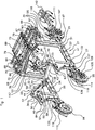
- the two side half-frames 21, 22 have the same shapes and dimensions. They are connected to each other rigidly by a front compass 41 and a rear compass 42 defining the transverse distance separating the two side half-frames 21, 22, that is to say the width of the frame, and allowing an adjustment of this width continuously between a minimum value and a maximum value.
- the left arm 43 is articulated to the right arm 44 by a central articulation 53 forming a non-sliding pivot with a vertical axis 54.
- the length of the arms 43, 44 is such that the vertical axis 54 of the central articulation 53 is equidistant from the two axes 51, 52 of the lateral articulations 49, 50.
- the left arm 43 has an extension 55 beyond the vertical axis 54 of the central joint 53.
- a jack 56 makes it possible to control the value of the angle, called the compass angle, formed between the two arms 43, 44 of the front compass 41.
- This jack 56 comprises a body 57 articulated to the right arm 44, and a rod 58 of actuation whose end is articulated to the extension 55 of the left arm 43.
- the actuating rod 58 of the jack 56 When the actuating rod 58 of the jack 56 is deployed, the compass angle decreases. When the actuating rod 58 of the cylinder 56 is retracted, the compass angle increases.
- the jack 56 is not supplied with liquid, it is locked in position, the front compass 41 also being locked in a determined angular position.
- the arms 43, 44 of the front compass 41 also advantageously have perforated plates 59, in particular pairs of vertically superimposed perforated plates provided with vertical holes. In the embodiment shown, these perforated plates 59 are provided at the rear of the arms 43, 44 of the front compass 41. None prevents to provide, as a variant or in combination, that similar plates are provided at the front. arms 43, 44 of the front compass 41.
- the front compass 41 is arranged such that the compass angle which it forms is less than 180 ° and has a vertex always facing forward.
- the left arm 63 is articulated to the right arm 64 by a central articulation 73 forming a non-sliding pivot with a vertical axis 74.
- the length of the arms 63, 64 is such that the vertical axis 74 of the central articulation 73 is equidistant from the two axes 71, 72 of the lateral articulations 69, 70.
- the right arm 64 has an extension 75 beyond the vertical axis 74 of the central articulation 73.
- a jack 76 makes it possible to control the value of the angle, called the compass angle, formed between the two arms 63, 64 of the rear compass 42.
- This jack 76 comprises a body 77 articulated to the left arm 63, and a rod 78 of actuation, the end of which is articulated to the extension 75 of the right arm 64.
- the actuating rod 78 of the jack 76 When the actuating rod 78 of the jack 76 is deployed, the compass angle decreases.
- the actuator rod 78 of the cylinder 76 When the actuator rod 78 of the cylinder 76 is retracted, the compass angle increases.
- the cylinder 76 is not supplied with liquid, it is locked in position, the rear compass 42 also being locked in a determined angular position.
- At least a first reinforcement jack is used to avoid undesired rotation at the level of the connections between each arm of at least one front compass and the two side half-frames.
- a first reinforcing cylinder is used to avoid undesired rotation at the level of the connections between each arm of the front compass and the two side half-frames.
- a second reinforcement cylinder is used to prevent unwanted rotation at the level of the connections between each arm of the rear compass and the two side half-frames.
- the first reinforcement cylinder comprises a body articulated to the left front upright, and an actuating rod, the end of which is articulated to the left arm of the front compass.
- the second reinforcement cylinder comprises a body articulated to the right rear upright, and an actuating rod, the end of which is articulated to the right arm of the rear compass.
- each reinforcement jack is placed on the inside of the compass to which it is assembled, that is to say between the two arms of the compass.
- the jacks 56 and 76 are arranged on the outer side of the compass to which they are assembled, the outer side being opposite to the inner side.
- the arms 63, 64 of the rear compass 42 also advantageously have perforated plates 79, in particular pairs of vertically superimposed perforated plates provided with vertical holes allowing the attachment of agricultural processing equipment or devices.
- these perforated plates 79 are provided at the front of the arms 63, 64 of the rear compass 42.
- the rear compass 42 is arranged such that the compass angle which it forms is less than 180 ° and has a vertex which is always oriented towards the rear.
- the left 43, 63 and right 44, 64 arms of the compasses 41, 42 have the same lengths.
- the front 41 and rear 42 calipers have the same shapes and dimensions and the jacks 56, 76 are identical so that, in any position for adjusting the width of the frame, the front 41 and rear 42 calipers have the same value of. compass angle, their tops being oriented in opposite directions, and the side members 23, 24 of the two side half-frames 21, 22 are parallel to each other and define a longitudinal axis of the frame and of the agricultural vehicle.
- the front 41 and rear 42 calipers both extend in the same horizontal plane. However, nothing prevents the front 41 and rear 42 compasses from extending in separate horizontal planes.
- each articulation of each compass 41, 42 can be produced in any way that is well known in itself, in particular by plain bearings and / or bearings.
- the chassis according to the invention thus formed is generally symmetrical with respect to a median longitudinal vertical plane. It is also generally symmetrical with respect to a median transverse vertical plane, except for the exact shape and dimensions of the front plates 33, 34 which are slightly different from those of the rear plates 35, 36. It is very high rigidity and very high resistance for low weight and great simplicity. It allows a simple and reliable adjustment of the width of the frame by modifying the compass angle of the calipers 41, 42. It allows a large central space to be left for the installation of different agricultural treatment devices, which can be arranged. both in height and in the immediate vicinity of the ground.
- the rear perforated plates 35, 36 have extensions 85, 86 respectively extending horizontally cantilevered rearwardly from the upper ends 67, 68 of the rear uprights 29, 30.
- Horizontal cross members 87 are attached to the rear. extension 85 of the left rear perforated plates 35 so as to extend above the horizontal plane of the compasses 41, 42.
- Horizontal cross members 88 are also attached to the extension 86 of the right rear perforated plates 36 so as to extend above the horizontal plane of the compasses 41, 42, the right cross members 88 being offset longitudinally from the left cross members 87.
- the cross members 87, 88 support a plate 89 formed, in the example shown, of a metal frame. To do this, the crosspieces 87, 88 are slidably mounted under the plate 89.
- Each cross member 87, 88 has a length which is less than or equal to, or slightly greater than, the overall width of the frame defined by the side half-frames 21, 22 in the minimum width position.
- the width of the plate 89 is less than or equal to, or slightly greater than, the overall width of the frame defined by the side half-frames 21, 22 in position. minimum width.
- the cross members 87, 88 and the plate 89 do not substantially project outwards beyond the side half-frames 21, 22.
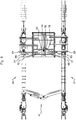
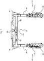
- the compasses 41, 42 in position of minimum width ( figure 3 ), have a compass angle which is of the order of 45 °. In this position of minimum width, the overall width of the frame may for example typically be of the order of 0.8 m. In maximum width position (especially figure 6 ), the compasses 41, 42 have a compass angle which is of the order of 150 °. In this position of maximum width, the overall width of the frame may for example be typically of the order of 2 m. Other values are possible.
- the front perforated plates 33, 34 also advantageously have extensions 83, 84 respectively extending horizontally in cantilever towards the front of the upper ends 47, 48 of the front uprights 25, 26. These extensions 83, 84 allow in particular the attachment of agricultural treatment equipment or devices. Although not shown in the embodiment illustrated in the figures, a horizontal plate may also be provided, supported by sliding cross members fixed to the extensions 83, 84 before.
- the rear plate 89 makes it possible in particular to support a heat engine 90 and its reservoir 91, an accumulator battery 94, a hydraulic unit 92 associated with this heat engine 90, connected by pipes and valves to the various hydraulic actuators of the vehicle and adapted to supply a pressurized liquid, and an electronic control unit 93 for the entire vehicle, the hydraulic unit 92 and the various actuators, including those of the agricultural treatment devices that can be installed on the vehicle.
- this unit 93 makes it possible to control the jacks 56, 76 of the callipers 41, 42 to vary the distance between the two half-frames 21, 22 and the frame width.
- each jack 56, 76 is advantageously provided with a position sensor, for example of the type with inductive sensor connected to the unit 93 for it. deliver a signal representative of the position of the actuating rod of the jack.
- the unit 93 is adapted to control the two jacks 56, 76 in synchronism.
- a left front wheel 95 is mounted in the lower part towards the front of the left front upright 25
- a right front wheel 96 is mounted in lower part towards the front of the right front upright 26
- a left rear wheel 97 is mounted in the lower part towards the rear of the left rear upright 29
- a right rear wheel 98 is mounted in the lower part towards the rear of the rear upright right 30.
- Each wheel 95 to 98 is directional, driving and independent, that is to say can be oriented and driven in rotation independently of the other wheels.
- Each wheel 95 to 98 is orientable with respect to the longitudinal axis at an orientation angle which may be between 0 ° and 90 °.
- an orientation angle of 0 ° for each of the wheels ( figure 1 in particular)
- the vehicle moves along the longitudinal axis.
- an orientation angle of 90 ° ( figure 2 ) of each of the wheels 95 to 98 the vehicle moves orthogonally to the longitudinal axis.
- the width adjustment of the chassis which corresponds to an adjustment of the track of the vehicle according to the invention, can be easily achieved by simple actuation.
- jacks 56, 76 can be easily achieved by simple actuation.
- Each wheel 95 to 98 is coupled to the horizontal motor shaft of a hydraulic motor 105, respectively 106, 107, 108 which is specific to it.
- This motor 105 to 108 is carried at the lower end of a hub carrier 109, respectively 110, 111, 112 mounted to pivot about a vertical axis relative to a hoop 114, respectively 115, 116, 117 assembled to the upright 25, 26, 29, 30 of the corresponding lateral half-frame 21, 22 and carrying an actuator 118, respectively 119, 120, 121 (rotary actuator) arranged to control the angular position of the hub carrier 109, respectively 110, 111, 112
- the hoop 114 to 117 is advantageously assembled at the lower end of the upright 25, 26, 29, 30 by means of a structure 122, respectively 123, 124, 125 with a deformable parallelogram.
- Each structure 122 to 125 with a deformable parallelogram has two pivots 126, 127 articulated one above the other to the upright 25, 26, 29, 30 (in particular to the perforated plates 33 to 36 fixed to this upright) along axes horizontal pivoting, two pivots 128, 129 articulated one above the other to the hoop 114 to 117 according to horizontal pivot axes.
- the plane of the pivot axes of the pivots 126, 127 is parallel to the plane of the pivot axes of the pivots 128, 129. These planes are at least substantially vertical.
- Two parallel arms 130, 131 of the same length connect the pivots 126 to 129 so as to form a deformable parallelogram.
- a first arm 130 connects the upper pivots 126 and 128.
- a second arm 131 connects the lower pivots 127 and 129.
- a jack 132, respectively 133, 134, 135 is interposed between the upright 25, 26, 29, 30 and the upper arm 130 of each structure 122, respectively 123, 124, 125 with a deformable parallelogram.
- Each cylinder 132 to 135 comprises a cylinder body 136 articulated along a horizontal pivot axis transverse to the corresponding upright 25, 26, 29, 30 (in particular to the perforated plates 33 to 36 fixed to this upright), and an actuating rod 137 articulated along a horizontal pivot axis transverse to the upper arm 130.
- a mounting flange 145 as shown figure 9 , comprising two perforated lateral flanges 146 carrying a plate 147 provided with a coupling hook 148 able to receive a ball coupling of agricultural tools.
- the flanges 146 and the holes they comprise are adapted to allow the removable fixing by bolts of the mounting flange 145 between the parallel perforated plates of each pair of perforated plates 33 to 36 of the frame.
- a mounting flange 145 is thus shown by way of example attached to the right front upright 26 on the figure 2 .
- the figures 10 and 11 show an example of agricultural equipment that can be installed on a frame according to the invention for mulching mounds of earth.
- This tool comprises a support 151 mounted on the left side half-frame 21 and a right-hand support 152 mounted on the right side half-frame 22.
- Each support 151, 152 is attached to the corresponding rear upright 29, 30 by a mounting flange 145. receiving a ball 153, 154 for coupling the support 151, 152 as described above.
- Each support 151, 152 is also supported by the corresponding side member 23, 24 by means of a bracket 155, 156.
- Each support 151, 152 is fixed to the corresponding front upright 25, 26 by a mounting flange 145 receiving a ball 157, 158 d 'hitching of the support 151, 152.
- Each support 151, 152 also comprises a pair of rollers 163, 164 mounted to rotate freely at the end of the arms about transverse horizontal axes of rotation, the rollers of each pair of rollers being spaced apart. longitudinally in order to be able to receive between them and to guide in rotation a roll 165 of mulch film extending along the width of the frame, in the upper part of the supports 151, 152 as shown figure 10 .
- Each support 151, 152 also carries inside the corresponding half-frame 21, 22, a disc 166, 167 mounted freely to rotate relative to the support 151, 152 about an axis of rotation 168, 169 transverse horizontal, the axes rotation 168, 169 of the two discs 166, 167 being collinear.
- the two discs 166, 167 have the same dimension, are parallel to one another, each extend in a longitudinal vertical plane and allow the unwinding and application of the mulch film around a mound of earth as represented figure 11 .
- the width of the frame is adjusted to a low value chosen as a function of the width of the mound of earth to be mulched, for example to its minimum value, so that the two discs66, 167 extend on one side and the other of the mound of earth.
- the figure 12 shows an example of bidirectional hoeing tool that can be installed in a removable manner on a frame according to the invention.
- the tooling also comprises a left support 171 mounted on the left side half-frame 21 and a right support 172 mounted on the right side half-frame 22.
- Each support 171, 172 is fixed to the rear upright 29, 30 corresponding by a mounting flange 145 receiving a ball 173, 174 for coupling the support 171, 172 as described above.
- Each support 171, 172 is also supported by the corresponding side member 23, 24 by means of a bracket 175, 176.
- Each support 171, 172 is fixed to the corresponding front upright 25, 26 by a mounting flange 145 receiving a ball 177, 178 d 'hitching of the support 171, 172.
- Each support 171, 172 carries a bearing 179, 180 for guiding in rotation a transverse horizontal shaft 181 of a bidirectional hoeing crew 182 comprising, at the rear of the transverse shaft 181 , hoeing tools 183 adapted to hoe the earth when the vehicle is moving forward, and, at the front of the transverse shaft 181, hoeing tools 184 adapted to hoe the earth when the vehicle is moving forward. the back.
- the angular position of the shaft 181 and of the hoeing crew 182 is adjusted by a jack 185 interposed between the right support 172 and a connecting rod 186 integral in rotation with the shaft 181.
- a jack 185 interposed between the right support 172 and a connecting rod 186 integral in rotation with the shaft 181.
- the tools 183 forward hoeing are in the low working position and the rear hoeing tools 184 are in the inactive high position.
- the jack 185 is deployed, the forward hoeing tools 183 are in the inactive high position and the rear hoeing tools 184 are in the low working position.
- agricultural treatment devices can be installed on a frame according to the invention: spraying devices, reservoirs, pruning tools, plowing tools, seed drills, vegetation mulching tools, mowing tools, planting tools, lifting tools and accessories, spreading tools, watering tools, drip applicator or others irrigation apparatus, dewatering tools, weeding tools, trimming tools, harvesting or collecting tools or accessories.
- a vehicle according to the invention can include a protective body 140.
- tools 142, 143 mark eradicators can be attached to the rear of the rear wheels 97, 98.
- a vehicle according to the invention can also include a seat and a driving position for the vehicle by a pilot carried by the vehicle.
- a seat can be fixed, for example, in the lower part of the frame, on the outward side of one of the side members 23, 24. It can also be used to receive a human operator carrying out manual treatment.
- a vehicle according to the invention can be remotely controlled, either by a human operator using a remote control, or even automatically and robotically from a control unit.
- a control unit can also even be incorporated into the vehicle according to the invention which is then entirely autonomous in its movements and can be guided by means of a satellite location and / or by any device known in itself allowing the autonomous guidance of self-propelled vehicles.
- the invention applies to any agricultural vehicle, in particular for market gardening, viticulture, arboriculture, field crops (in particular cereals and oilseeds).
- the same vehicle according to the invention can easily be used by the farmer for different applications, for example market gardening and / or viticulture and / or arboriculture and / or asparagus or other cultivation.
Landscapes
- Engineering & Computer Science (AREA)
- Chemical & Material Sciences (AREA)
- Combustion & Propulsion (AREA)
- Transportation (AREA)
- Mechanical Engineering (AREA)
- Agricultural Machines (AREA)
- Body Structure For Vehicles (AREA)
Priority Applications (1)
| Application Number | Priority Date | Filing Date | Title |
|---|---|---|---|
| PL19740643T PL3645376T3 (pl) | 2018-06-08 | 2019-06-07 | Rama pojazdu rolniczego o regulowanej szerokości i pojazd rolniczy |
Applications Claiming Priority (2)
| Application Number | Priority Date | Filing Date | Title |
|---|---|---|---|
| FR1855044A FR3082169B1 (fr) | 2018-06-08 | 2018-06-08 | Chassis de vehicule agricole de largeur reglable et vehicule agricole |
| PCT/FR2019/051375 WO2019234369A1 (fr) | 2018-06-08 | 2019-06-07 | Châssis de véhicule agricole de largeur réglable et véhicule agricole |
Publications (2)
| Publication Number | Publication Date |
|---|---|
| EP3645376A1 EP3645376A1 (fr) | 2020-05-06 |
| EP3645376B1 true EP3645376B1 (fr) | 2020-12-30 |
Family
ID=63312086
Family Applications (1)
| Application Number | Title | Priority Date | Filing Date |
|---|---|---|---|
| EP19740643.2A Not-in-force EP3645376B1 (fr) | 2018-06-08 | 2019-06-07 | Châssis de véhicule agricole de largeur réglable et véhicule agricole |
Country Status (6)
| Country | Link |
|---|---|
| US (1) | US20210245821A1 (pl) |
| EP (1) | EP3645376B1 (pl) |
| ES (1) | ES2863566T3 (pl) |
| FR (1) | FR3082169B1 (pl) |
| PL (1) | PL3645376T3 (pl) |
| WO (1) | WO2019234369A1 (pl) |
Families Citing this family (6)
| Publication number | Priority date | Publication date | Assignee | Title |
|---|---|---|---|---|
| US11420491B2 (en) * | 2017-09-19 | 2022-08-23 | Commonwealth Scientific And Industrial Research Organisation | Plant scanning vehicle |
| KR20220049393A (ko) * | 2020-10-14 | 2022-04-21 | 현대자동차주식회사 | 퍼스널 모빌리티 및 그 제어 방법 |
| ES1265465Y (es) * | 2021-01-21 | 2022-02-10 | Ianus Ingenieria S L U | Máquina polivalente para el cultivo de árboles. |
| CN113086012A (zh) * | 2021-05-24 | 2021-07-09 | 安徽信息工程学院 | 一种底盘可调节式移动机器人 |
| FR3139973B1 (fr) * | 2022-09-26 | 2024-12-13 | Romanesco | Machine agricole comportant une arche et un système de fixation particulier fixé à l’arche et assurant la fixation d’un outil |
| JP7803586B2 (ja) * | 2024-05-14 | 2026-01-21 | 株式会社FieldWorks | 無人移動体 |
Family Cites Families (5)
| Publication number | Priority date | Publication date | Assignee | Title |
|---|---|---|---|---|
| FR329501A (fr) * | 1903-02-18 | 1903-08-01 | Eugene Michel | Procédé et appareils déterminant l'intensité maximum du pouvoir calorique et photométrique obtenu par la combustion de l'alcool de toutes provenances, richesse et pureté, dans les réchauds ou lampes à alcool, par combustible liquide ou gazéifié, à flamme directe ou par incandescence |
| US6371237B1 (en) * | 2000-09-06 | 2002-04-16 | Hagie Manufacturing Company | Steering system for variable height agricultural sprayer |
| US9346497B2 (en) * | 2014-04-09 | 2016-05-24 | Hagie Manufacturing Company | Variable tread width vehicle |
| WO2015197173A1 (de) * | 2014-06-24 | 2015-12-30 | Scheuerle Fahrzeugfabrik Gmbh | Transportfahrzeug, insbesondere ein selbstangetriebenes transportfahrzeug, mit variabler breite |
| FR3058380B1 (fr) * | 2016-11-07 | 2019-07-19 | Vermande (SA) | Tracteur enjambeur |
-
2018
- 2018-06-08 FR FR1855044A patent/FR3082169B1/fr not_active Expired - Fee Related
-
2019
- 2019-06-07 PL PL19740643T patent/PL3645376T3/pl unknown
- 2019-06-07 ES ES19740643T patent/ES2863566T3/es active Active
- 2019-06-07 WO PCT/FR2019/051375 patent/WO2019234369A1/fr not_active Ceased
- 2019-06-07 EP EP19740643.2A patent/EP3645376B1/fr not_active Not-in-force
- 2019-06-07 US US16/973,403 patent/US20210245821A1/en not_active Abandoned
Non-Patent Citations (1)
| Title |
|---|
| None * |
Also Published As
| Publication number | Publication date |
|---|---|
| FR3082169A1 (fr) | 2019-12-13 |
| US20210245821A1 (en) | 2021-08-12 |
| ES2863566T3 (es) | 2021-10-11 |
| PL3645376T3 (pl) | 2021-07-12 |
| EP3645376A1 (fr) | 2020-05-06 |
| WO2019234369A1 (fr) | 2019-12-12 |
| FR3082169B1 (fr) | 2020-12-04 |
Similar Documents
| Publication | Publication Date | Title |
|---|---|---|
| EP3645376A1 (fr) | Châssis de véhicule agricole de largeur réglable et véhicule agricole | |
| EP2225933B1 (fr) | Dispositif de taille embarqué | |
| WO2011114016A1 (fr) | Tracteur enjambeur | |
| EP3599809B1 (fr) | Dispositif d'attelage pour engin agricole | |
| CA2833103A1 (fr) | Machine agricole avec un dispositif de repliage perfectionne | |
| EP0786201B1 (fr) | Robot taille-haies télécommandé avec réglage automatique des niveaux | |
| FR2817112A1 (fr) | Machine a chassis polyvalent pour le travail du sol dans les plantations d'arbres ou arbustes | |
| EP2210472B1 (fr) | Tête de récolte et machine automotrice enjambeuse en faisant application, utilisables pour la récolte de haies fruitières | |
| FR2816166A1 (fr) | Machine robotisee de taille d'arbustes ou d'arbres tels que des arbres fruitiers | |
| EP2820931B1 (fr) | Machine de travail du sol avec un dispositif de réglage de la profondeur de travail perfectionné | |
| EP3118378B1 (fr) | Engin de travail motorise et mobile | |
| EP2617278A1 (fr) | Equipement agricole pour un véhicule motorisé, avec parallélogramme déformable pour le déport latéral d'une partie outil | |
| FR3103347A1 (fr) | Dispositif de tonte interceps pour les cultures en rangs, notamment la vigne | |
| FR2485451A1 (fr) | Vehicule tracteur enjambeur a palonniers sustentateurs pour applications diverses | |
| FR2942370A1 (fr) | Dispositif formant taille-haie equipant un engin motorise, tel qu'un microtracteur ou une tondeuse autoportee. | |
| EP1319587A1 (fr) | Porte-outils pour culture en lignes et utilisation d'un tel porte-outils | |
| FR3091462A1 (fr) | Dispositif de faucheuse-débroussailleuse et engin roulant motorisé équipé d’un tel dispositif | |
| FR2506830A1 (fr) | Tariere pendulaire | |
| EP2397395B1 (fr) | véhicule porte-outil automoteur à 4 roues dissymétriques | |
| EP3973754B1 (fr) | Charrue réversible semi-portée à chariot ou monoroue | |
| WO2005015974A2 (fr) | Machine combinee forestiere pour le travail du sol | |
| FR2546122A1 (fr) | Tracteur ou vehicule similaire dont les roues directrices sont egalement motrices | |
| FR3002109A3 (fr) | Machine interceps pour le travail de la terre | |
| FR3067215B1 (fr) | Machine agricole de suppression d'epis parasites des cultures agricoles | |
| FR2743692A1 (fr) | Dispositif d'arrachage et de transplantation |
Legal Events
| Date | Code | Title | Description |
|---|---|---|---|
| STAA | Information on the status of an ep patent application or granted ep patent |
Free format text: STATUS: UNKNOWN |
|
| STAA | Information on the status of an ep patent application or granted ep patent |
Free format text: STATUS: THE INTERNATIONAL PUBLICATION HAS BEEN MADE |
|
| PUAI | Public reference made under article 153(3) epc to a published international application that has entered the european phase |
Free format text: ORIGINAL CODE: 0009012 |
|
| STAA | Information on the status of an ep patent application or granted ep patent |
Free format text: STATUS: EXAMINATION IS IN PROGRESS |
|
| 17P | Request for examination filed |
Effective date: 20200131 |
|
| AK | Designated contracting states |
Kind code of ref document: A1 Designated state(s): AL AT BE BG CH CY CZ DE DK EE ES FI FR GB GR HR HU IE IS IT LI LT LU LV MC MK MT NL NO PL PT RO RS SE SI SK SM TR |
|
| AX | Request for extension of the european patent |
Extension state: BA ME |
|
| GRAP | Despatch of communication of intention to grant a patent |
Free format text: ORIGINAL CODE: EPIDOSNIGR1 |
|
| STAA | Information on the status of an ep patent application or granted ep patent |
Free format text: STATUS: GRANT OF PATENT IS INTENDED |
|
| INTG | Intention to grant announced |
Effective date: 20200622 |
|
| GRAS | Grant fee paid |
Free format text: ORIGINAL CODE: EPIDOSNIGR3 |
|
| DAV | Request for validation of the european patent (deleted) | ||
| DAX | Request for extension of the european patent (deleted) | ||
| GRAA | (expected) grant |
Free format text: ORIGINAL CODE: 0009210 |
|
| STAA | Information on the status of an ep patent application or granted ep patent |
Free format text: STATUS: THE PATENT HAS BEEN GRANTED |
|
| AK | Designated contracting states |
Kind code of ref document: B1 Designated state(s): AL AT BE BG CH CY CZ DE DK EE ES FI FR GB GR HR HU IE IS IT LI LT LU LV MC MK MT NL NO PL PT RO RS SE SI SK SM TR |
|
| REG | Reference to a national code |
Ref country code: GB Ref legal event code: FG4D Free format text: NOT ENGLISH |
|
| REG | Reference to a national code |
Ref country code: DE Ref legal event code: R096 Ref document number: 602019001995 Country of ref document: DE |
|
| REG | Reference to a national code |
Ref country code: AT Ref legal event code: REF Ref document number: 1349681 Country of ref document: AT Kind code of ref document: T Effective date: 20210115 |
|
| REG | Reference to a national code |
Ref country code: IE Ref legal event code: FG4D Free format text: LANGUAGE OF EP DOCUMENT: FRENCH |
|
| REG | Reference to a national code |
Ref country code: RO Ref legal event code: EPE |
|
| PG25 | Lapsed in a contracting state [announced via postgrant information from national office to epo] |
Ref country code: RS Free format text: LAPSE BECAUSE OF FAILURE TO SUBMIT A TRANSLATION OF THE DESCRIPTION OR TO PAY THE FEE WITHIN THE PRESCRIBED TIME-LIMIT Effective date: 20201230 Ref country code: FI Free format text: LAPSE BECAUSE OF FAILURE TO SUBMIT A TRANSLATION OF THE DESCRIPTION OR TO PAY THE FEE WITHIN THE PRESCRIBED TIME-LIMIT Effective date: 20201230 Ref country code: GR Free format text: LAPSE BECAUSE OF FAILURE TO SUBMIT A TRANSLATION OF THE DESCRIPTION OR TO PAY THE FEE WITHIN THE PRESCRIBED TIME-LIMIT Effective date: 20210331 Ref country code: NO Free format text: LAPSE BECAUSE OF FAILURE TO SUBMIT A TRANSLATION OF THE DESCRIPTION OR TO PAY THE FEE WITHIN THE PRESCRIBED TIME-LIMIT Effective date: 20210330 |
|
| REG | Reference to a national code |
Ref country code: AT Ref legal event code: MK05 Ref document number: 1349681 Country of ref document: AT Kind code of ref document: T Effective date: 20201230 |
|
| PG25 | Lapsed in a contracting state [announced via postgrant information from national office to epo] |
Ref country code: BG Free format text: LAPSE BECAUSE OF FAILURE TO SUBMIT A TRANSLATION OF THE DESCRIPTION OR TO PAY THE FEE WITHIN THE PRESCRIBED TIME-LIMIT Effective date: 20210330 Ref country code: SE Free format text: LAPSE BECAUSE OF FAILURE TO SUBMIT A TRANSLATION OF THE DESCRIPTION OR TO PAY THE FEE WITHIN THE PRESCRIBED TIME-LIMIT Effective date: 20201230 Ref country code: LV Free format text: LAPSE BECAUSE OF FAILURE TO SUBMIT A TRANSLATION OF THE DESCRIPTION OR TO PAY THE FEE WITHIN THE PRESCRIBED TIME-LIMIT Effective date: 20201230 |
|
| REG | Reference to a national code |
Ref country code: NL Ref legal event code: MP Effective date: 20201230 |
|
| PG25 | Lapsed in a contracting state [announced via postgrant information from national office to epo] |
Ref country code: HR Free format text: LAPSE BECAUSE OF FAILURE TO SUBMIT A TRANSLATION OF THE DESCRIPTION OR TO PAY THE FEE WITHIN THE PRESCRIBED TIME-LIMIT Effective date: 20201230 |
|
| REG | Reference to a national code |
Ref country code: LT Ref legal event code: MG9D |
|
| PG25 | Lapsed in a contracting state [announced via postgrant information from national office to epo] |
Ref country code: CZ Free format text: LAPSE BECAUSE OF FAILURE TO SUBMIT A TRANSLATION OF THE DESCRIPTION OR TO PAY THE FEE WITHIN THE PRESCRIBED TIME-LIMIT Effective date: 20201230 Ref country code: EE Free format text: LAPSE BECAUSE OF FAILURE TO SUBMIT A TRANSLATION OF THE DESCRIPTION OR TO PAY THE FEE WITHIN THE PRESCRIBED TIME-LIMIT Effective date: 20201230 Ref country code: SK Free format text: LAPSE BECAUSE OF FAILURE TO SUBMIT A TRANSLATION OF THE DESCRIPTION OR TO PAY THE FEE WITHIN THE PRESCRIBED TIME-LIMIT Effective date: 20201230 Ref country code: LT Free format text: LAPSE BECAUSE OF FAILURE TO SUBMIT A TRANSLATION OF THE DESCRIPTION OR TO PAY THE FEE WITHIN THE PRESCRIBED TIME-LIMIT Effective date: 20201230 Ref country code: PT Free format text: LAPSE BECAUSE OF FAILURE TO SUBMIT A TRANSLATION OF THE DESCRIPTION OR TO PAY THE FEE WITHIN THE PRESCRIBED TIME-LIMIT Effective date: 20210430 |
|
| PGFP | Annual fee paid to national office [announced via postgrant information from national office to epo] |
Ref country code: RO Payment date: 20210527 Year of fee payment: 3 |
|
| PG25 | Lapsed in a contracting state [announced via postgrant information from national office to epo] |
Ref country code: AT Free format text: LAPSE BECAUSE OF FAILURE TO SUBMIT A TRANSLATION OF THE DESCRIPTION OR TO PAY THE FEE WITHIN THE PRESCRIBED TIME-LIMIT Effective date: 20201230 |
|
| PGFP | Annual fee paid to national office [announced via postgrant information from national office to epo] |
Ref country code: PL Payment date: 20210528 Year of fee payment: 3 |
|
| PG25 | Lapsed in a contracting state [announced via postgrant information from national office to epo] |
Ref country code: IS Free format text: LAPSE BECAUSE OF FAILURE TO SUBMIT A TRANSLATION OF THE DESCRIPTION OR TO PAY THE FEE WITHIN THE PRESCRIBED TIME-LIMIT Effective date: 20210430 |
|
| REG | Reference to a national code |
Ref country code: DE Ref legal event code: R097 Ref document number: 602019001995 Country of ref document: DE |
|
| REG | Reference to a national code |
Ref country code: ES Ref legal event code: FG2A Ref document number: 2863566 Country of ref document: ES Kind code of ref document: T3 Effective date: 20211011 |
|
| PG25 | Lapsed in a contracting state [announced via postgrant information from national office to epo] |
Ref country code: AL Free format text: LAPSE BECAUSE OF FAILURE TO SUBMIT A TRANSLATION OF THE DESCRIPTION OR TO PAY THE FEE WITHIN THE PRESCRIBED TIME-LIMIT Effective date: 20201230 |
|
| PLBE | No opposition filed within time limit |
Free format text: ORIGINAL CODE: 0009261 |
|
| STAA | Information on the status of an ep patent application or granted ep patent |
Free format text: STATUS: NO OPPOSITION FILED WITHIN TIME LIMIT |
|
| PG25 | Lapsed in a contracting state [announced via postgrant information from national office to epo] |
Ref country code: DK Free format text: LAPSE BECAUSE OF FAILURE TO SUBMIT A TRANSLATION OF THE DESCRIPTION OR TO PAY THE FEE WITHIN THE PRESCRIBED TIME-LIMIT Effective date: 20201230 |
|
| 26N | No opposition filed |
Effective date: 20211001 |
|
| PG25 | Lapsed in a contracting state [announced via postgrant information from national office to epo] |
Ref country code: MC Free format text: LAPSE BECAUSE OF FAILURE TO SUBMIT A TRANSLATION OF THE DESCRIPTION OR TO PAY THE FEE WITHIN THE PRESCRIBED TIME-LIMIT Effective date: 20201230 |
|
| PG25 | Lapsed in a contracting state [announced via postgrant information from national office to epo] |
Ref country code: SI Free format text: LAPSE BECAUSE OF FAILURE TO SUBMIT A TRANSLATION OF THE DESCRIPTION OR TO PAY THE FEE WITHIN THE PRESCRIBED TIME-LIMIT Effective date: 20201230 |
|
| REG | Reference to a national code |
Ref country code: BE Ref legal event code: MM Effective date: 20210630 |
|
| PG25 | Lapsed in a contracting state [announced via postgrant information from national office to epo] |
Ref country code: LU Free format text: LAPSE BECAUSE OF NON-PAYMENT OF DUE FEES Effective date: 20210607 |
|
| PG25 | Lapsed in a contracting state [announced via postgrant information from national office to epo] |
Ref country code: IE Free format text: LAPSE BECAUSE OF NON-PAYMENT OF DUE FEES Effective date: 20210607 |
|
| PG25 | Lapsed in a contracting state [announced via postgrant information from national office to epo] |
Ref country code: IS Free format text: LAPSE BECAUSE OF FAILURE TO SUBMIT A TRANSLATION OF THE DESCRIPTION OR TO PAY THE FEE WITHIN THE PRESCRIBED TIME-LIMIT Effective date: 20210430 |
|
| PG25 | Lapsed in a contracting state [announced via postgrant information from national office to epo] |
Ref country code: BE Free format text: LAPSE BECAUSE OF NON-PAYMENT OF DUE FEES Effective date: 20210630 |
|
| PG25 | Lapsed in a contracting state [announced via postgrant information from national office to epo] |
Ref country code: RO Free format text: LAPSE BECAUSE OF NON-PAYMENT OF DUE FEES Effective date: 20220607 |
|
| REG | Reference to a national code |
Ref country code: CH Ref legal event code: PL |
|
| PG25 | Lapsed in a contracting state [announced via postgrant information from national office to epo] |
Ref country code: LI Free format text: LAPSE BECAUSE OF NON-PAYMENT OF DUE FEES Effective date: 20220630 Ref country code: CH Free format text: LAPSE BECAUSE OF NON-PAYMENT OF DUE FEES Effective date: 20220630 |
|
| PG25 | Lapsed in a contracting state [announced via postgrant information from national office to epo] |
Ref country code: NL Free format text: LAPSE BECAUSE OF NON-PAYMENT OF DUE FEES Effective date: 20201230 Ref country code: CY Free format text: LAPSE BECAUSE OF FAILURE TO SUBMIT A TRANSLATION OF THE DESCRIPTION OR TO PAY THE FEE WITHIN THE PRESCRIBED TIME-LIMIT Effective date: 20201230 |
|
| PG25 | Lapsed in a contracting state [announced via postgrant information from national office to epo] |
Ref country code: SM Free format text: LAPSE BECAUSE OF FAILURE TO SUBMIT A TRANSLATION OF THE DESCRIPTION OR TO PAY THE FEE WITHIN THE PRESCRIBED TIME-LIMIT Effective date: 20201230 Ref country code: HU Free format text: LAPSE BECAUSE OF FAILURE TO SUBMIT A TRANSLATION OF THE DESCRIPTION OR TO PAY THE FEE WITHIN THE PRESCRIBED TIME-LIMIT; INVALID AB INITIO Effective date: 20190607 |
|
| PGFP | Annual fee paid to national office [announced via postgrant information from national office to epo] |
Ref country code: GB Payment date: 20231127 Year of fee payment: 5 |
|
| PGFP | Annual fee paid to national office [announced via postgrant information from national office to epo] |
Ref country code: ES Payment date: 20231124 Year of fee payment: 5 |
|
| PGFP | Annual fee paid to national office [announced via postgrant information from national office to epo] |
Ref country code: IT Payment date: 20231129 Year of fee payment: 5 Ref country code: FR Payment date: 20231129 Year of fee payment: 5 Ref country code: DE Payment date: 20231129 Year of fee payment: 5 |
|
| PG25 | Lapsed in a contracting state [announced via postgrant information from national office to epo] |
Ref country code: MK Free format text: LAPSE BECAUSE OF FAILURE TO SUBMIT A TRANSLATION OF THE DESCRIPTION OR TO PAY THE FEE WITHIN THE PRESCRIBED TIME-LIMIT Effective date: 20201230 |
|
| PG25 | Lapsed in a contracting state [announced via postgrant information from national office to epo] |
Ref country code: PL Free format text: LAPSE BECAUSE OF NON-PAYMENT OF DUE FEES Effective date: 20220607 |
|
| PG25 | Lapsed in a contracting state [announced via postgrant information from national office to epo] |
Ref country code: MT Free format text: LAPSE BECAUSE OF FAILURE TO SUBMIT A TRANSLATION OF THE DESCRIPTION OR TO PAY THE FEE WITHIN THE PRESCRIBED TIME-LIMIT Effective date: 20201230 |
|
| REG | Reference to a national code |
Ref country code: DE Ref legal event code: R119 Ref document number: 602019001995 Country of ref document: DE |
|
| GBPC | Gb: european patent ceased through non-payment of renewal fee |
Effective date: 20240607 |
|
| PG25 | Lapsed in a contracting state [announced via postgrant information from national office to epo] |
Ref country code: DE Free format text: LAPSE BECAUSE OF NON-PAYMENT OF DUE FEES Effective date: 20250101 |
|
| PG25 | Lapsed in a contracting state [announced via postgrant information from national office to epo] |
Ref country code: FR Free format text: LAPSE BECAUSE OF NON-PAYMENT OF DUE FEES Effective date: 20240630 |
|
| PG25 | Lapsed in a contracting state [announced via postgrant information from national office to epo] |
Ref country code: GB Free format text: LAPSE BECAUSE OF NON-PAYMENT OF DUE FEES Effective date: 20240607 Ref country code: IT Free format text: LAPSE BECAUSE OF NON-PAYMENT OF DUE FEES Effective date: 20240607 |
|
| REG | Reference to a national code |
Ref country code: ES Ref legal event code: FD2A Effective date: 20250728 |
|
| PG25 | Lapsed in a contracting state [announced via postgrant information from national office to epo] |
Ref country code: ES Free format text: LAPSE BECAUSE OF NON-PAYMENT OF DUE FEES Effective date: 20240608 |
|
| PG25 | Lapsed in a contracting state [announced via postgrant information from national office to epo] |
Ref country code: TR Free format text: LAPSE BECAUSE OF FAILURE TO SUBMIT A TRANSLATION OF THE DESCRIPTION OR TO PAY THE FEE WITHIN THE PRESCRIBED TIME-LIMIT Effective date: 20201230 |