EP3973754B1 - Charrue réversible semi-portée à chariot ou monoroue - Google Patents
Charrue réversible semi-portée à chariot ou monoroue Download PDFInfo
- Publication number
- EP3973754B1 EP3973754B1 EP21196761.7A EP21196761A EP3973754B1 EP 3973754 B1 EP3973754 B1 EP 3973754B1 EP 21196761 A EP21196761 A EP 21196761A EP 3973754 B1 EP3973754 B1 EP 3973754B1
- Authority
- EP
- European Patent Office
- Prior art keywords
- axis
- swivel joint
- bearing
- frame
- joint bearing
- Prior art date
- Legal status (The legal status is an assumption and is not a legal conclusion. Google has not performed a legal analysis and makes no representation as to the accuracy of the status listed.)
- Active
Links
Images


Classifications
-
- A—HUMAN NECESSITIES
- A01—AGRICULTURE; FORESTRY; ANIMAL HUSBANDRY; HUNTING; TRAPPING; FISHING
- A01B—SOIL WORKING IN AGRICULTURE OR FORESTRY; PARTS, DETAILS, OR ACCESSORIES OF AGRICULTURAL MACHINES OR IMPLEMENTS, IN GENERAL
- A01B3/00—Ploughs with fixed plough-shares
- A01B3/46—Ploughs supported partly by tractor and partly by their own wheels
- A01B3/464—Alternating ploughs with frame rotating about a horizontal axis, e.g. turn-wrest ploughs
- A01B3/466—Alternating ploughs with frame rotating about a horizontal axis, e.g. turn-wrest ploughs the frame comprising an articulated beam
-
- A—HUMAN NECESSITIES
- A01—AGRICULTURE; FORESTRY; ANIMAL HUSBANDRY; HUNTING; TRAPPING; FISHING
- A01B—SOIL WORKING IN AGRICULTURE OR FORESTRY; PARTS, DETAILS, OR ACCESSORIES OF AGRICULTURAL MACHINES OR IMPLEMENTS, IN GENERAL
- A01B15/00—Elements, tools, or details of ploughs
- A01B15/14—Frames
Definitions
- the present invention relates to the field of agricultural machinery and in particular the technical field of plows, and in particular reversible semi-mounted plows, and aims at an improved plow of this type.
- Ploughs of the type mentioned above generally comprise a structure in two parts (front and rear) articulated together and each consisting of a frame part carrying pairs of opposing ploughing bodies. These two parts are located on either side of a carriage or a support wheel (resting on the ground at least during the work or use phases).
- This plough further comprises at least one means for turning the two frame parts with the ploughing bodies (two working positions: ploughing on the right and ploughing on the left) and a coupling device for attaching and connecting the front part to a towing vehicle.
- a plow of this type is known in particular from the document EP 1 157 600 .
- This document discloses a semi-mounted reversible plough with a carriage or single wheel, moved in use in a direction of advance and comprising a front part of the main frame and a rear part of the main frame, each of which carries ploughing bodies.
- These two parts of the main frame with their ploughing bodies are respectively integral with front and rear parts of a connecting frame mutually connected by an articulated connection (here of the complex type combining a slide, a stop and a pivot) connecting the two parts of the main frame together via these two parts.
- This plough also comprises a support frame with a fixed front part, integral with the carriage or the wheel, and a tilting rear part, connected to the fixed front part by a pivoting assembly bearing with an axis perpendicular to the direction of advance.
- the tilting rear part implements a multitude of different elements such as a tilting lever, a cylinder, two articulations and at least one spacer.
- the front part of the connecting frame is connected to the fixed front part of the support frame by a front pivot joint bearing with an axis parallel to the forward direction
- the rear part of the connecting frame is connected to the fixed front part of the support frame by a front pivot joint bearing with an axis parallel to the forward direction
- the rear part of the connecting frame is connected to the fixed front part of the support frame by a front pivot joint bearing with an axis parallel to the forward direction.
- This known construction therefore comprises a mechanism for easily lifting the rear part of the main frame and keeping it in this raised position during turning, with relatively few components and therefore with low additional cost and weight.
- this mechanism it is possible to prevent the last plough bodies from coming into contact with the ground during the turning phase to switch from right-hand ploughing to left-hand ploughing and vice versa.
- the rear part of the plough can be positioned substantially parallel to the ground during transport.
- the present invention aims to overcome these drawbacks and to propose a structurally and functionally improved version of the plow known from the document EP 1 157 600 .
- the invention proposes a semi-mounted plough of the type mentioned above and which is characterized in that the axis of the front pivoting articulation bearing intersects the axis of the pivoting assembly bearing at the level of said pivoting assembly bearing.
- the Figures 1 and 2 , and the Figures 3 to 5 partially, show a semi-mounted reversible plough (1) with a carriage (2) or single wheel, moved in use in a direction of advance (DA).
- the plough (1) comprises a structure in several parts articulated together.
- the plough shown comprises a front part (3') of the main frame (3) and a rear part (3") of the main frame (3), each of which carries ploughing bodies (4).
- These two main frame parts (3' and 3") are respectively integral with front (5') and rear (5") parts of a connecting frame (5) mutually connected by an articulated connection (6) connecting the two main frame parts (3' and 3") together via them.
- the articulated connection (6) has an axis (A6) substantially perpendicular to the direction of advance (DA).
- the front part (5') of the connecting frame carries a pair of bodies (4).
- This plough (1) also comprises a support frame (7) with a fixed front part (7'), integral with the carriage (2) or the wheel, and a tilting rear part (7"), connected to the fixed front part (7') by a pivoting assembly bearing (8) with an axis (A8) perpendicular to the direction of advance (DA).
- This axis (A8) is advantageously parallel to the axis of rotation of the two wheels of the carriage or the single wheel.
- the axis (A9) of the front pivot joint bearing (9) intersects the axis (A8) of the pivot assembly bearing (8) at said pivot assembly bearing (8).
- the point of intersection between the axes (A9) and (A8) is located substantially in the middle of the physical joint forming the bearing (8).
- the invention allows a simplification of the kinematics to be achieved. Thanks to this kinematics, the rear part of the plough (1) is automatically in its appropriate position, raised relative to the ground as soon as it leaves the ground so that the turning can take place. After the turning (changing from ploughing on the right to ploughing on the left and vice versa) the plough (1) is directly in position to enter the ground and continue plowing. Compared to the aforementioned known plough, the kinematics according to the invention are also more stable.
- the axes (A9) and (A10) respectively of the front and rear pivoting articulation bearings (9 and 10) are located in the same vertical plane (PV), and are preferentially mutually aligned.
- the axis or one (A6) of the articulation axes of the articulated connection (6) connecting the front and rear parts (5' and 5") of the connection frame (5) crosses or intersects the axis (A8) of the bearing pivoting assembly (8).
- the left wheel (not shown) runs on the unplowed soil surface while the right wheel runs in the ploughed furrow, which means that the axis passing through the axle or the two wheels is substantially inclined (relative to the plane of the unplowed soil surface or to the horizontal).
- the fixed front part (7') is then inclined accordingly, as is the pivoting assembly bearing (8) and in particular its axis (A8).
- the axis (A6) of the articulated connection (6) is, on the other hand, parallel to the soil surface.
- This articulated connection (6) connecting the front and rear parts (5' and 5") of the connection frame (5) can take different forms, such as a single pivot connection, at least two associated pivot connections or even a cardan connection.
- this articulated connection (6) consists of a ball joint, possibly with a limited ability to rotate around the axis (A6). In addition to providing multiple degrees of freedom, useful precisely for said connection (6), it is a compact and economical construction solution.
- this front part (3') can be connected to the fixed front part (7') of the support frame (7) by a second pivot joint bearing (11), located between the front pivot joint bearing (9) and the rear pivot joint bearing (10) and aligned with said front pivot joint bearing (9), preferably extending in front of said pivot assembly bearing (8) and having an axis (A11) intersecting the axis (A8) of the latter and merging with the axis (A9) of the front pivot joint bearing (9).
- a second pivot joint bearing (11) located between the front pivot joint bearing (9) and the rear pivot joint bearing (10) and aligned with said front pivot joint bearing (9), preferably extending in front of said pivot assembly bearing (8) and having an axis (A11) intersecting the axis (A8) of the latter and merging with the axis (A9) of the front pivot joint bearing (9).
- FIG 2 illustrates the reversible plough (1) in its transport position.
- the left wheel is not shown on the figure 2 for better visibility around the fixed front part (7') and the tilting rear part (7") of the chassis support (7).
- the front part (3') of the main frame (3) is substantially inclined relative to the ground surface while the rear part (3") is substantially parallel to the ground surface.
- the figure 1 illustrates the working position of the plough (1).
- the plough bodies (4) are oriented so that their respective counter-parts are parallel to the direction of advance (A).
- the front part (3') and the rear part (3") are parallel to each other, when viewed from above.
- the left wheel of the carriage (2) runs in the ploughing furrow made by the last plough body (4) of the front part (3') or, as shown here, the plough body (4) fixed to the front part (5') of the connecting frame (5).
- the second pivot joint bearing (11) is located closer to the rear pivot joint bearing (10) than to the front pivot joint bearing (9), advantageously close to the pivot assembly bearing (8).
- a connecting rod (12) articulated at its two ends secures the element (10') of the rear pivoting articulation bearing (10), which is movable relative to the rear part (7") of the support frame (7), with the rear part (5") of the connecting frame (5).
- the plough (1) also comprises a means (13) for turning the front (3') and rear (3") parts of the main frame (3), for example in the form of a jack, connected to the front part (5') of the connecting frame (5) for driving the latter, said turning means (13) being on the other hand advantageously connected to the fixed front part (7') of the support frame (7), preferably at the level of the front pivoting articulation bearing (9).
- An actuating means (16), for example of the jack type, is also provided for tilting the movable rear part (7") of the support frame (7) around its pivoting assembly bearing (8) with the fixed rear part (7'), which is preferably directly mounted on the axle or hubs of the trolley (2).
- the actuating means (16) is configured to ensure the ground tracking of the plow. The working depth is ensured by the depth wheel positioned close to the front end of the front part (3') and the depth wheel positioned on the rear part (3").
- the actuating means (16) is free, that is to say that the position of the piston is floating.
- the actuating means (16) can be piloted or locked.
- the plow (1) When plowing, when the plow (1) reaches the headland, i.e. at the edge of the field, it is the front part (3') of the main frame (3) which rises first, then the rear part (3"). The plow is said to come out of the ground, the different plowing bodies (4) come out of the ground gradually.
- the operator operates the tractor lift, then the actuator located between the fixed front part (7') of the support carriage (7) and the carriage (2). He then operates the actuating means (16) which will lift the rear part (3") with its plowing bodies and finally the turning means (13).
- the rear part (3") of the main frame (3) is secured to the rear part (5") of the connecting frame (5) by means of an articulated connection (14).
- This articulated connection (14) may consist, in a non-limiting manner, of: a simple pivot connection, a combined pivot+slide connection or even at least two parallel elementary connections, such as for example a multi-branch connection comprising three connecting rods (15, 15', 15") mounted in parallel and each connecting the two aforementioned rear parts (3" and 5") together, with mutual subjection of these two parts in respective parallel planes.
Landscapes
- Life Sciences & Earth Sciences (AREA)
- Engineering & Computer Science (AREA)
- Mechanical Engineering (AREA)
- Soil Sciences (AREA)
- Environmental Sciences (AREA)
- Soil Working Implements (AREA)
- Agricultural Machines (AREA)
Description
- La présente invention concerne le domaine du machinisme agricole et en particulier le domaine technique des charrues, et notamment des charrues semi-portées réversibles, et vise une charrue améliorée de ce type.
- Les charrues du type évoqué ci-dessus comprennent généralement une structure en deux parties (avant et arrière) articulées entre elles et constituées chacune par une partie de bâti portant des couples de corps de labour opposés. Ces deux parties sont situées de part et d'autre d'un chariot ou d'une roue de support (en appui au sol au moins durant les phases de travail ou d'utilisation). Cette charrue comprend en outre au moins un moyen de retournement des deux parties de bâti avec les corps de labour (deux positions de travail : labour à droite et labour à gauche) et un dispositif d'attelage pour l'accrochage et le raccordement de la partie avant à un véhicule tracteur.
- Une charrue de ce type est notamment connue du document
EP 1 157 600 . - Ce document divulgue une charrue réversible semi-portée à chariot ou monoroue, déplacée en utilisation selon une direction d'avance et comprenant une partie avant de bâti principal et une partie arrière de bâti principal dont chacune porte des corps de labour. Ces deux parties de bâti principal avec leurs corps de labour sont respectivement solidaires de parties avant et arrière d'un cadre de liaison reliées mutuellement par une liaison articulée (ici du type complexe combinant une coulisse, une butée et un pivot) connectant les deux parties de bâti principal entre elles par l'intermédiaire de ces deux parties. Cette charrue comprend également un châssis support avec une partie avant fixe, solidaire du chariot ou de la roue, et une partie arrière basculante, reliée à la partie avant fixe par un palier d'assemblage pivotant avec un axe perpendiculaire à la direction d'avance. La partie arrière basculante met en oeuvre une multitude d'éléments différents tels qu'un levier basculant, un vérin, deux articulations et d'au moins une entretoise. La partie avant du bâti de liaison est reliée à la partie avant fixe du châssis support par un palier d'articulation pivotante avant avec un axe parallèle à la direction d'avance, et la partie arrière du bâti de liaison est reliée à la partie arrière basculante du châssis support par un palier d'articulation pivotante arrière avec un axe situé dans un plan contenant la direction d'avance, les paliers d'articulation pivotante avant et arrière formant des paliers de guidage aux fins de retournement respectivement des parties avant et arrière du bâti principal.
- Cette construction connue comporte donc un mécanisme permettant de soulever facilement la partie arrière du bâti principal et de la conserver dans cette position relevée pendant le retournement, avec relativement peu de composants et donc avec un surcoût et un surpoids faibles. Grâce à ce mécanisme, il est possible d'éviter que les derniers corps de labour n'entrent en contact avec le sol lors de la phase de retournement pour passer d'un labour à droite à un labour à gauche et vice-versa. De plus, la partie arrière de la charrue peut être positionnée sensiblement parallèlement au sol lors du transport.
- Toutefois, cette construction connue est encore relativement complexe, présente des points de faiblesse constructive et surtout manque de stabilité à l'usage. Des constructions de charrues réversibles sensiblement similaires et présentant les mêmes inconvénients sont également connues des documents
EP 1 082 888 etDE 9205455 . - La présente invention a pour but de pallier ces inconvénients et de proposer une version structurellement et fonctionnellement améliorée de la charrue connue par le document
EP 1 157 600 . - A cet effet, l'invention propose une charrue semi-portée du type évoqué ci-dessus et qui est caractérisée en ce que l'axe du palier d'articulation pivotante avant coupe l'axe du palier d'assemblage pivotant au niveau dudit palier d'assemblage pivotant.
- L'invention sera mieux comprise, grâce à la description ci-après, qui se rapporte à un mode de réalisation préféré, donné à titre d'exemple non limitatif, et expliqué avec référence aux dessins schématiques annexés, dans lesquels :
- [
Fig. 1 ] représente en vue de dessus une charrue réversible semi-portée avec un chariot dans une position de travail, selon un mode de réalisation de l'invention (seul un corps de labour de chaque couple de corps de labour est visible du fait de leur superposition mutuelle) ; - [
Fig. 2 ] est une vue en élévation latérale de la charrue de lafigure 1 en position de transport ; - [
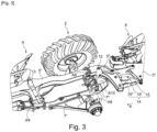
Fig. 3 ] est une vue partielle en perspective et à une autre échelle de la région du chariot (roue de gauche enlevée) et du bâti ou cadre de liaison faisant partie de la charrue desfigures 1 et 2 , dans une des positions de travail de ladite charrue ; - [
Fig. 4 ] est une vue en élévation latérale de l'objet représentéfigure 3 , et, - [
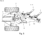
Fig. 5 ] est une vue partielle de dessus et à une autre échelle du chariot, du bâti de liaison et de la partie arrière faisant partie de la charrue desfigures 1 et 2 , dans la position desfigures 3 et4 . - Les
figures 1 et 2 , et lesfigures 3 à 5 de manière partielle, montrent une charrue réversible (1) semi-portée à chariot (2) ou monoroue, déplacée en utilisation selon une direction d'avance (DA). La charrue (1) comprend une structure en plusieurs parties articulées entre elles. La charrue représentée comprend une partie avant (3') de bâti principal (3) et une partie arrière (3") de bâti principal (3) dont chacune porte des corps de labour (4). Ces deux parties de bâti principal (3' et 3") sont respectivement solidaires de parties avant (5') et arrière (5") d'un bâti de liaison (5) reliées mutuellement par une liaison articulée (6) connectant les deux parties de bâti principal (3' et 3") entre elles par leur intermédiaire. La liaison articulée (6) présente un axe (A6) sensiblement perpendiculaire à la direction d'avance (DA). Dans l'exemple de réalisation représenté auxfigures 1 et 2 , la partie avant (5') du bâti de liaison porte une paire de corps (4). Cette charrue (1) comprend également un châssis support (7) avec une partie avant fixe (7'), solidaire du chariot (2) ou de la roue, et une partie arrière basculante (7"), reliée à la partie avant fixe (7') par un palier d'assemblage pivotant (8) avec un axe (A8) perpendiculaire à la direction d'avance (DA). Cet axe (A8) est avantageusement parallèle à l'axe de rotation des deux roues du chariot ou de la monoroue. - La partie avant (5') de bâti de liaison (5) est reliée à la partie avant fixe (7') du châssis support (7) par un palier d'articulation pivotante avant (9) d'axe (A9) parallèle à la direction d'avance (DA), et la partie arrière (5") de bâti de liaison (5) est reliée à la partie arrière basculante (7") du châssis support (7) par un palier d'articulation pivotante arrière (10) d'axe (A10) situé dans un plan contenant la direction d'avance (DA). Ces paliers d'articulation pivotante avant et arrière (9 et 10) forment des paliers de guidage du retournement respectivement des parties avant et arrière (3' et 3") du bâti principal (3).
- Conformément à l'invention, l'axe (A9) du palier d'articulation pivotante avant (9) coupe l'axe (A8) du palier d'assemblage pivotant (8) au niveau dudit palier d'assemblage pivotant (8). Préférentiellement, le point d'intersection entre les axes (A9) et (A8) est situé sensiblement au milieu de l'articulation physique formant le palier (8).
- Du fait de cette disposition constructive, l'invention permet d'aboutir à une simplification de la cinématique. Grâce à cette cinématique, la partie arrière de la charrue (1) est automatiquement dans sa position adéquate, relevée par rapport au sol dès la sortie de terre pour que le retournement puisse se faire. Après le retournement (passage de labour à droite à labour à gauche et inversement) la charrue (1) est directement en position pour faire une entrée en terre et poursuivre le labour. Par rapport à la charrue connue précitée, la cinématique selon l'invention est aussi plus stable.
- Préférentiellement, l'axe (A10) du palier d'articulation pivotante arrière (10) coupe également l'axe (A8) du palier d'assemblage pivotant (8) au niveau dudit palier d'assemblage pivotant (8), et le point d'intersection entre les axes (A10) et (A8) est avantageusement aussi situé sensiblement au milieu de l'articulation physique formant le palier d'assemblage pivotant (8). Le palier d'assemblage pivotant (8) est avantageusement réalisé en une seule pièce sous la forme d'un fourreau. Selon une construction alternative, le palier d'assemblage pivotant (8) peut être réalisé en deux parties.
- En accord avec une autre caractéristique favorable à une simplification de la cinématique, il peut être prévu que, en position de travail de la charrue (1), les axes (A9) et (A10) respectivement des paliers d'articulation pivotante avant et arrière (9 et 10) sont situés dans un même plan vertical (PV), et sont préférentiellement mutuellement alignés.
- Selon une autre caractéristique constructive en faveur de la simplification de la cinématique, il peut être prévu que, en position de travail de la charrue (1), l'axe ou l'un (A6) des axes d'articulation de la liaison articulée (6) reliant les parties avant et arrière (5' et 5") du bâti de liaison (5) croise ou coupe l'axe (A8) du palier d'assemblage pivotant (8). En effet, lors du travail ou du labour, avec la charrue semi-portée à chariot (2) représentée à la
figure 4 , la roue gauche (non représentée) circule sur la surface du sol non labourée alors que la roue droite circule dans la raie de labour, ce qui veut dire que l'axe passant par l'essieu ou les deux roues est sensiblement incliné (par rapport au plan de la surface du sol non labourée ou à l'horizontale). La partie avant fixe (7') est alors inclinée en conséquence, tout comme le palier d'assemblage pivotant (8) et notamment son axe (A8). L'axe (A6) de la liaison articulée (6) est par contre parallèle à la surface du sol. - Cette liaison articulée (6) reliant les parties avant et arrière (5' et 5") du bâti de liaison (5) peut se présenter sous différentes formes, telles qu'une liaison pivot unique, au moins deux liaisons pivots associées ou encore une liaison à cardan.
- Toutefois, de manière préférée, cette liaison articulée (6) consiste en une liaison rotule, éventuellement avec une faculté de rotulage limité autour de l'axe (A6). En plus de fournir des degrés de liberté multiples, utiles précisément pour ladite liaison (6), il s'agit d'une solution constructive compacte et économique.
- Afin de fournir à la partie avant (3') de bâti principal (3) un support additionnel et un guidage supplémentaire lors du retournement, cette partie avant (3') peut être reliée à la partie avant fixe (7') du châssis support (7) par un second palier d'articulation pivotante (11), situé entre le palier d'articulation pivotante avant (9) et le palier d'articulation pivotante arrière (10) et aligné avec ledit palier d'articulation pivotante avant (9), en s'étendant de préférence devant ledit palier d'assemblage pivotant (8) et en présentant un axe (A11) coupant l'axe (A8) de ce dernier et confondu avec l'axe (A9) du palier d'articulation pivotante avant (9).
- Préférentiellement, les axes (A9), (A10) et (A11) sont tous strictement confondus en position de travail de la charrue (1), comme le montre la
figure 4 . Dans la position de transport, les axes (A9) et (A11) sont confondus mais l'axe (A10) coupe les axes (A9) et (A11) puisque la partie arrière basculante (7") est relevée. - La
figure 2 illustre la charrue (1) réversible dans sa position de transport. La roue gauche n'est pas représentée sur lafigure 2 pour une meilleure visibilité autour de la partie avant fixe (7') et de la partie arrière basculante (7") du châssis support (7). On remarque que la partie avant (3') du bâti principal (3) est sensiblement inclinée par rapport à la surface du sol alors que la partie arrière (3") est sensiblement parallèle à la surface du sol. Lafigure 1 illustre la position de travail de la charrue (1). On constate que les corps de labour (4) sont orientés de façon à ce que leur contresep respectif soit parallèle à la direction d'avance (A). La partie avant (3') et la partie arrière (3") sont parallèles l'une par rapport à l'autre, en vue de dessus. La roue gauche du chariot (2) circule dans la raie de labour réalisé par le dernier corps de labour (4) de la partie avant (3') ou, comme représenté ici, le corps de labour (4) fixé sur la partie avant (5') du bâti de liaison (5). - Avantageusement, le second pallier d'articulation pivotante (11) est situé plus proche du palier d'articulation pivotante arrière (10) que du palier d'articulation pivotante avant (9), avantageusement à proximité du palier d'assemblage pivotant (8).
- La mise en oeuvre d'un second palier (11) permet d'aboutir à une construction plus solide et plus rigide de la charrue (1), ainsi qu'à un guidage plus précis lors du retournement.
- En accord avec une caractéristique constructive additionnelle de l'invention, une biellette (12) articulée à ses deux extrémités solidarise l'élément (10') du palier d'articulation pivotante arrière (10), qui est mobile par rapport à la partie arrière (7") du châssis support (7), avec la partie arrière (5") du bâti de liaison (5).
- Comme le montrent à titre d'exemple les
figures 1 à 3 , la charrue (1) comprend également un moyen de retournement (13) des parties avant (3') et arrière (3") de bâti principal (3), par exemple sous la forme d'un vérin, relié à la partie avant (5') du bâti de liaison (5) pour l'entrainement de ce dernier, ledit moyen de retournement (13) étant d'autre part avantageusement relié à la partie avant fixe (7') du châssis support (7), préférentiellement au niveau du palier d'articulation pivotante avant (9). - Un moyen d'actionnement (16), par exemple du type vérin, est aussi prévu pour basculer la partie arrière mobile (7") du châssis support (7) autour de son palier d'assemblage pivotant (8) avec la partie arrière fixe (7'), qui est préférentiellement directement monté sur l'essieu ou les moyeux du chariot (2). D'une manière avantageuse, le moyen d'actionnement (16) est configuré pour assurer le suivi de terrain de la charrue. La profondeur de travail est assurée par la roue de profondeur positionnée proche de l'extrémité avant de la partie avant (3') et la roue de profondeur positionnée sur la partie arrière (3"). Ainsi lors du travail ou du labour, le moyen d'actionnement (16) est libre, c'est-à-dire que la position du piston est flottante. Dans une alternative constructive toutefois, le moyen d'actionnement (16) peut être piloté ou verrouillé.
- Lors du labour, lorsque la charrue (1) arrive dans la fourrière, c'est-à-dire au bord du champ, c'est la partie avant (3') du bâti principal (3) qui se lève d'abord puis la partie arrière (3"). On dit que la charrue sort du sol, les différents corps de labour (4) sortent de terre au fur et à mesure. Généralement, l'opérateur actionne le relevage du tracteur, puis l'actionneur situé entre la partie avant fixe (7') du chariot support (7) et le chariot (2). Il actionne ensuite le moyen d'actionnement (16) qui va soulever la partie arrière (3") avec ses corps de labour et finalement le moyen de retournement (13).
- Selon une caractéristique constructive supplémentaire de l'invention, ressortant des
figures 1 à 3 et5 à titre d'exemple, la partie arrière (3") de bâti principal (3) est solidarisée avec la partie arrière (5") du bâti de liaison (5) par le biais d'une liaison articulée (14). - Cette liaison articulée (14) peut consister de manière non limitative en : une liaison pivot simple, une liaison combinée pivot+glissière ou encore au moins deux liaisons élémentaires parallèles, comme par exemple une liaison multi-branches comprenant trois biellettes (15, 15', 15") montées en parallèle et reliant chacune les deux parties arrières précitées (3" et 5") entre elles, avec assujettissement mutuel de ces deux parties dans des plans parallèles respectifs.
- Bien entendu, l'invention n'est pas limitée au mode de réalisation décrit et représenté aux dessins annexés. Des modifications restent possibles, notamment du point de vue de la constitution des divers éléments ou par substitution d'équivalents techniques, sans sortir pour autant du domaine de protection de l'invention, lorsque l'étendu de protection de la revendication 1 est respecté.
Claims (10)
- Charrue réversible (1) semi-portée à chariot (2) ou monoroue, déplacée en utilisation selon une direction d'avance (DA) et comprenant une partie avant (3') de bâti principal (3) et une partie arrière (3") de bâti principal (3) dont chacune porte des corps de labour (4), ces deux parties de bâti principal (3' et 3") étant respectivement solidaires de parties avant (5') et arrière (5") d'un bâti de liaison (5) reliées mutuellement par une liaison articulée (6) connectant les deux parties de bâti principal (3' et 3") entre elles par leur intermédiaire, ladite charrue (1) comprenant également un châssis support (7) avec une partie avant fixe (7'), solidaire du chariot (2) ou de la roue, et une partie arrière basculante (7"), reliée à la partie avant fixe (7') par un palier d'assemblage pivotant (8) avec un axe (A8) perpendiculaire à la direction d'avance (DA), la partie avant (5') de bâti de liaison (5) étant reliée à la partie avant fixe (7') du châssis support (7) par un palier d'articulation pivotante avant (9) d'axe (A9) parallèle à la direction d'avance (DA), et la partie arrière (5") de bâti de liaison (5) étant reliée à la partie arrière basculante (7") du châssis support (7) par un palier d'articulation pivotante arrière (10) d'axe (A10) situé dans un plan contenant la direction d'avance (DA), les paliers d'articulation pivotante avant et arrière (9 et 10) formant des paliers de guidage du retournement respectivement des parties avant et arrière (3' et 3") du bâti principal (3),
charrue (1) caractérisée en ce que l'axe (A9) du palier d'articulation pivotante avant (9) coupe l'axe (A8) du palier d'assemblage pivotant (8) au niveau dudit palier d'assemblage pivotant (8). - Charrue selon la revendication 1, caractérisée en ce que l'axe (A10) du palier d'articulation pivotante arrière (10) coupe l'axe (A8) du palier d'assemblage pivotant (8) au niveau dudit palier d'assemblage pivotant (8).
- Charrue selon la revendication 1 ou 2, caractérisée en ce que, en position de travail, les axes (A9) et (A10) des paliers d'articulation pivotante avant et arrière (9 et 10) respectivement sont situés dans un même plan vertical (PV), et sont préférentiellement mutuellement alignés.
- Charrue selon l'une quelconque des revendications 1 à 3, caractérisée en ce que, en position de travail, l'axe (A6) ou l'un des axes d'articulation de la liaison articulée (6) reliant les parties avant et arrière (5' et 5") du bâti de liaison (5) coupe l'axe (A8) du palier d'assemblage pivotant (8).
- Charrue selon l'une quelconque des revendications 1 à 4, caractérisée en ce que la liaison articulée (6) reliant les parties avant et arrière (5' et 5") du bâti de liaison (5) consiste en une liaison rotule.
- Charrue selon l'une quelconque des revendications 1 à 5, caractérisée en ce que la partie avant (3') de bâti principal (3) est reliée à la partie avant fixe (7') du châssis support (7) par un second palier d'articulation pivotante (11), situé entre le palier d'articulation pivotante avant (9) et le palier d'articulation pivotante arrière (10) et aligné avec ledit palier d'articulation pivotante avant (9), en s'étendant de préférence devant ledit palier d'assemblage pivotant (8) et en présentant un axe (A11) coupant l'axe (A8) de ce dernier et confondu avec l'axe (A9) du palier d'articulation pivotante avant (9).
- Charrue selon la revendication 6, caractérisée en ce que le second palier d'articulation pivotante (11) est situé plus proche du palier d'articulation pivotante arrière (10) que du palier d'articulation pivotante avant (9).
- Charrue selon l'une quelconque des revendications 1 à 7, caractérisée en ce qu'une biellette (12) articulée à ses deux extrémités solidarise l'élément du palier d'articulation pivotante arrière (10), qui est mobile par rapport à la partie arrière (7") du châssis support (7), avec la partie arrière (5") du bâti de liaison (5).
- Charrue selon l'une quelconque des revendications 1 à 8, caractérisée en ce qu'elle comprend également un moyen de retournement (13) des parties avant (3') et arrière (3") de bâti principal (3), par exemple sous la forme d'un vérin, relié à la partie avant (5') du bâti de liaison (5) pour l'entrainement de ce dernier, ledit moyen de retournement (13) étant d'autre part avantageusement relié à la partie avant fixe (7') du châssis support (7), préférentiellement au niveau du palier d'articulation pivotante avant (9)
- Charrue selon l'une quelconque des revendications 1 à 8, caractérisée en ce que la partie arrière (3") de bâti principal (3) est solidarisée avec la partie arrière (5") du bâti de liaison (5) par le biais d'une liaison articulée (14).
Applications Claiming Priority (1)
| Application Number | Priority Date | Filing Date | Title |
|---|---|---|---|
| FR2009812A FR3114478B1 (fr) | 2020-09-28 | 2020-09-28 | Charrue réversible du type portée ou semi-portée à chariot ou monoroue |
Publications (2)
| Publication Number | Publication Date |
|---|---|
| EP3973754A1 EP3973754A1 (fr) | 2022-03-30 |
| EP3973754B1 true EP3973754B1 (fr) | 2024-08-28 |
Family
ID=73498022
Family Applications (1)
| Application Number | Title | Priority Date | Filing Date |
|---|---|---|---|
| EP21196761.7A Active EP3973754B1 (fr) | 2020-09-28 | 2021-09-15 | Charrue réversible semi-portée à chariot ou monoroue |
Country Status (4)
| Country | Link |
|---|---|
| EP (1) | EP3973754B1 (fr) |
| DK (1) | DK3973754T3 (fr) |
| ES (1) | ES2993216T3 (fr) |
| FR (1) | FR3114478B1 (fr) |
Family Cites Families (3)
| Publication number | Priority date | Publication date | Assignee | Title |
|---|---|---|---|---|
| DE9205455U1 (de) * | 1992-04-22 | 1992-07-02 | Rabewerk GmbH + Co, 4515 Bad Essen | Aufsattel- oder Anhänge-Drehpflug |
| ATE233468T1 (de) * | 1999-09-10 | 2003-03-15 | Lemken Gmbh & Co Kg | Aufsattel- bzw. anhängedrehpflug mit zugpunktregelung |
| EP1157600A1 (fr) | 2000-05-20 | 2001-11-28 | Lemken GmbH & Co. KG | Charrue réversible semi-portée ou traínée |
-
2020
- 2020-09-28 FR FR2009812A patent/FR3114478B1/fr active Active
-
2021
- 2021-09-15 ES ES21196761T patent/ES2993216T3/es active Active
- 2021-09-15 EP EP21196761.7A patent/EP3973754B1/fr active Active
- 2021-09-15 DK DK21196761.7T patent/DK3973754T3/da active
Also Published As
| Publication number | Publication date |
|---|---|
| DK3973754T3 (da) | 2024-10-28 |
| ES2993216T3 (en) | 2024-12-26 |
| FR3114478A1 (fr) | 2022-04-01 |
| FR3114478B1 (fr) | 2022-09-23 |
| EP3973754A1 (fr) | 2022-03-30 |
Similar Documents
| Publication | Publication Date | Title |
|---|---|---|
| EP2524583B1 (fr) | Charrue semi-portée monoroue à largeur de travail réglable | |
| EP2353351A1 (fr) | Charrue semi-portée réversible hors raie | |
| EP3698612A1 (fr) | Charrue avec un dispositif de compensation de l'effort latéral en cours de labour | |
| FR2806871A1 (fr) | Machine de fenaison comportant au moins une roue rateleuse articulee sur un bras porteur | |
| EP2959759B1 (fr) | Machine agricole munie d'un dispositif de centrage | |
| EP4039073B1 (fr) | Dispositif de repliage de transport par mécanisme articulé | |
| FR2935218A1 (fr) | Charrue portee comportant un bras de roue perfectionne. | |
| EP3973754A1 (fr) | Charrue réversible du type portée ou semi-portée à chariot ou monoroue | |
| EP1634488B1 (fr) | Chariot à roues de jauge et de transport et charrue réversible portée équipée d'un tel chariot | |
| EP0857413A1 (fr) | Machine de fenaison | |
| EP2241170B1 (fr) | Chariot porteur pour charrue semi-portée | |
| FR2851120A1 (fr) | Charrue reversible semi-porte | |
| EP0831686B1 (fr) | Charrue multi-socs reversible semi-portee | |
| EP1068782B1 (fr) | Pulvérisateur agricole | |
| FR2607351A1 (fr) | Systeme d'attelage a une charrue brabant d'un appareil agricole a remorquer | |
| FR2647297A1 (fr) | Instrument aratoire comprenant un outil compose d'un element central en avant de deux elements lateraux pivotants | |
| EP0561709B1 (fr) | Perfectionnement aux charrues multisocs | |
| FR2967864A1 (fr) | Charrue semi-portee avec un organe de nettoyage de roue perfectionne | |
| EP0872167A1 (fr) | Dispositif de réglage et de déplacement latéral des corps d'une charrue | |
| FR3114477A1 (fr) | Charrue semi-portée avec un dispositif de compensation de l’effort latéral généré par ladite charrue en cours d’utilisation | |
| FR2551015A1 (fr) | Vehicule a train avant et chassis deportables lateralement relativement | |
| FR2658694A1 (fr) | Charrue reversible semi-portee sur deux roues. | |
| WO1997015177A1 (fr) | Charrue reversible portee a largeur variable avec dispositif de recentrage du bati sur l'axe de retournement | |
| FR2644029A1 (fr) | Dispositif d'attelage pivotant pour outil agricole de grande largeur | |
| EP1797750A1 (fr) | Charrue réversible portée avec roue de transport latérale |
Legal Events
| Date | Code | Title | Description |
|---|---|---|---|
| PUAI | Public reference made under article 153(3) epc to a published international application that has entered the european phase |
Free format text: ORIGINAL CODE: 0009012 |
|
| STAA | Information on the status of an ep patent application or granted ep patent |
Free format text: STATUS: THE APPLICATION HAS BEEN PUBLISHED |
|
| AK | Designated contracting states |
Kind code of ref document: A1 Designated state(s): AL AT BE BG CH CY CZ DE DK EE ES FI FR GB GR HR HU IE IS IT LI LT LU LV MC MK MT NL NO PL PT RO RS SE SI SK SM TR |
|
| STAA | Information on the status of an ep patent application or granted ep patent |
Free format text: STATUS: REQUEST FOR EXAMINATION WAS MADE |
|
| 17P | Request for examination filed |
Effective date: 20220927 |
|
| RBV | Designated contracting states (corrected) |
Designated state(s): AL AT BE BG CH CY CZ DE DK EE ES FI FR GB GR HR HU IE IS IT LI LT LU LV MC MK MT NL NO PL PT RO RS SE SI SK SM TR |
|
| P01 | Opt-out of the competence of the unified patent court (upc) registered |
Effective date: 20230622 |
|
| GRAP | Despatch of communication of intention to grant a patent |
Free format text: ORIGINAL CODE: EPIDOSNIGR1 |
|
| STAA | Information on the status of an ep patent application or granted ep patent |
Free format text: STATUS: GRANT OF PATENT IS INTENDED |
|
| INTG | Intention to grant announced |
Effective date: 20240222 |
|
| GRAS | Grant fee paid |
Free format text: ORIGINAL CODE: EPIDOSNIGR3 |
|
| GRAJ | Information related to disapproval of communication of intention to grant by the applicant or resumption of examination proceedings by the epo deleted |
Free format text: ORIGINAL CODE: EPIDOSDIGR1 |
|
| GRAL | Information related to payment of fee for publishing/printing deleted |
Free format text: ORIGINAL CODE: EPIDOSDIGR3 |
|
| STAA | Information on the status of an ep patent application or granted ep patent |
Free format text: STATUS: REQUEST FOR EXAMINATION WAS MADE |
|
| GRAP | Despatch of communication of intention to grant a patent |
Free format text: ORIGINAL CODE: EPIDOSNIGR1 |
|
| STAA | Information on the status of an ep patent application or granted ep patent |
Free format text: STATUS: GRANT OF PATENT IS INTENDED |
|
| INTC | Intention to grant announced (deleted) | ||
| GRAA | (expected) grant |
Free format text: ORIGINAL CODE: 0009210 |
|
| STAA | Information on the status of an ep patent application or granted ep patent |
Free format text: STATUS: THE PATENT HAS BEEN GRANTED |
|
| INTG | Intention to grant announced |
Effective date: 20240704 |
|
| AK | Designated contracting states |
Kind code of ref document: B1 Designated state(s): AL AT BE BG CH CY CZ DE DK EE ES FI FR GB GR HR HU IE IS IT LI LT LU LV MC MK MT NL NO PL PT RO RS SE SI SK SM TR |
|
| REG | Reference to a national code |
Ref country code: CH Ref legal event code: EP |
|
| REG | Reference to a national code |
Ref country code: DE Ref legal event code: R096 Ref document number: 602021017820 Country of ref document: DE |
|
| REG | Reference to a national code |
Ref country code: IE Ref legal event code: FG4D Free format text: LANGUAGE OF EP DOCUMENT: FRENCH |
|
| REG | Reference to a national code |
Ref country code: DK Ref legal event code: T3 Effective date: 20241025 |
|
| REG | Reference to a national code |
Ref country code: AT Ref legal event code: UEP Ref document number: 1716893 Country of ref document: AT Kind code of ref document: T Effective date: 20240828 |
|
| REG | Reference to a national code |
Ref country code: ES Ref legal event code: FG2A Ref document number: 2993216 Country of ref document: ES Kind code of ref document: T3 Effective date: 20241226 |
|
| REG | Reference to a national code |
Ref country code: LT Ref legal event code: MG9D |
|
| PG25 | Lapsed in a contracting state [announced via postgrant information from national office to epo] |
Ref country code: NL Free format text: LAPSE BECAUSE OF FAILURE TO SUBMIT A TRANSLATION OF THE DESCRIPTION OR TO PAY THE FEE WITHIN THE PRESCRIBED TIME-LIMIT Effective date: 20240828 Ref country code: PL Free format text: LAPSE BECAUSE OF FAILURE TO SUBMIT A TRANSLATION OF THE DESCRIPTION OR TO PAY THE FEE WITHIN THE PRESCRIBED TIME-LIMIT Effective date: 20240828 Ref country code: GR Free format text: LAPSE BECAUSE OF FAILURE TO SUBMIT A TRANSLATION OF THE DESCRIPTION OR TO PAY THE FEE WITHIN THE PRESCRIBED TIME-LIMIT Effective date: 20241129 Ref country code: FI Free format text: LAPSE BECAUSE OF FAILURE TO SUBMIT A TRANSLATION OF THE DESCRIPTION OR TO PAY THE FEE WITHIN THE PRESCRIBED TIME-LIMIT Effective date: 20240828 Ref country code: PT Free format text: LAPSE BECAUSE OF FAILURE TO SUBMIT A TRANSLATION OF THE DESCRIPTION OR TO PAY THE FEE WITHIN THE PRESCRIBED TIME-LIMIT Effective date: 20241230 |
|
| PG25 | Lapsed in a contracting state [announced via postgrant information from national office to epo] |
Ref country code: BG Free format text: LAPSE BECAUSE OF FAILURE TO SUBMIT A TRANSLATION OF THE DESCRIPTION OR TO PAY THE FEE WITHIN THE PRESCRIBED TIME-LIMIT Effective date: 20240828 |
|
| PG25 | Lapsed in a contracting state [announced via postgrant information from national office to epo] |
Ref country code: LV Free format text: LAPSE BECAUSE OF FAILURE TO SUBMIT A TRANSLATION OF THE DESCRIPTION OR TO PAY THE FEE WITHIN THE PRESCRIBED TIME-LIMIT Effective date: 20240828 |
|
| REG | Reference to a national code |
Ref country code: NL Ref legal event code: MP Effective date: 20240828 |
|
| PG25 | Lapsed in a contracting state [announced via postgrant information from national office to epo] |
Ref country code: IS Free format text: LAPSE BECAUSE OF FAILURE TO SUBMIT A TRANSLATION OF THE DESCRIPTION OR TO PAY THE FEE WITHIN THE PRESCRIBED TIME-LIMIT Effective date: 20241228 |
|
| PG25 | Lapsed in a contracting state [announced via postgrant information from national office to epo] |
Ref country code: HR Free format text: LAPSE BECAUSE OF FAILURE TO SUBMIT A TRANSLATION OF THE DESCRIPTION OR TO PAY THE FEE WITHIN THE PRESCRIBED TIME-LIMIT Effective date: 20240828 |
|
| PG25 | Lapsed in a contracting state [announced via postgrant information from national office to epo] |
Ref country code: RS Free format text: LAPSE BECAUSE OF FAILURE TO SUBMIT A TRANSLATION OF THE DESCRIPTION OR TO PAY THE FEE WITHIN THE PRESCRIBED TIME-LIMIT Effective date: 20241128 |
|
| PG25 | Lapsed in a contracting state [announced via postgrant information from national office to epo] |
Ref country code: RS Free format text: LAPSE BECAUSE OF FAILURE TO SUBMIT A TRANSLATION OF THE DESCRIPTION OR TO PAY THE FEE WITHIN THE PRESCRIBED TIME-LIMIT Effective date: 20241128 Ref country code: PT Free format text: LAPSE BECAUSE OF FAILURE TO SUBMIT A TRANSLATION OF THE DESCRIPTION OR TO PAY THE FEE WITHIN THE PRESCRIBED TIME-LIMIT Effective date: 20241230 Ref country code: PL Free format text: LAPSE BECAUSE OF FAILURE TO SUBMIT A TRANSLATION OF THE DESCRIPTION OR TO PAY THE FEE WITHIN THE PRESCRIBED TIME-LIMIT Effective date: 20240828 Ref country code: NL Free format text: LAPSE BECAUSE OF FAILURE TO SUBMIT A TRANSLATION OF THE DESCRIPTION OR TO PAY THE FEE WITHIN THE PRESCRIBED TIME-LIMIT Effective date: 20240828 Ref country code: LV Free format text: LAPSE BECAUSE OF FAILURE TO SUBMIT A TRANSLATION OF THE DESCRIPTION OR TO PAY THE FEE WITHIN THE PRESCRIBED TIME-LIMIT Effective date: 20240828 Ref country code: IS Free format text: LAPSE BECAUSE OF FAILURE TO SUBMIT A TRANSLATION OF THE DESCRIPTION OR TO PAY THE FEE WITHIN THE PRESCRIBED TIME-LIMIT Effective date: 20241228 Ref country code: HR Free format text: LAPSE BECAUSE OF FAILURE TO SUBMIT A TRANSLATION OF THE DESCRIPTION OR TO PAY THE FEE WITHIN THE PRESCRIBED TIME-LIMIT Effective date: 20240828 Ref country code: GR Free format text: LAPSE BECAUSE OF FAILURE TO SUBMIT A TRANSLATION OF THE DESCRIPTION OR TO PAY THE FEE WITHIN THE PRESCRIBED TIME-LIMIT Effective date: 20241129 Ref country code: FI Free format text: LAPSE BECAUSE OF FAILURE TO SUBMIT A TRANSLATION OF THE DESCRIPTION OR TO PAY THE FEE WITHIN THE PRESCRIBED TIME-LIMIT Effective date: 20240828 Ref country code: BG Free format text: LAPSE BECAUSE OF FAILURE TO SUBMIT A TRANSLATION OF THE DESCRIPTION OR TO PAY THE FEE WITHIN THE PRESCRIBED TIME-LIMIT Effective date: 20240828 |
|
| PG25 | Lapsed in a contracting state [announced via postgrant information from national office to epo] |
Ref country code: RO Free format text: LAPSE BECAUSE OF FAILURE TO SUBMIT A TRANSLATION OF THE DESCRIPTION OR TO PAY THE FEE WITHIN THE PRESCRIBED TIME-LIMIT Effective date: 20240828 Ref country code: SM Free format text: LAPSE BECAUSE OF FAILURE TO SUBMIT A TRANSLATION OF THE DESCRIPTION OR TO PAY THE FEE WITHIN THE PRESCRIBED TIME-LIMIT Effective date: 20240828 |
|
| PG25 | Lapsed in a contracting state [announced via postgrant information from national office to epo] |
Ref country code: EE Free format text: LAPSE BECAUSE OF FAILURE TO SUBMIT A TRANSLATION OF THE DESCRIPTION OR TO PAY THE FEE WITHIN THE PRESCRIBED TIME-LIMIT Effective date: 20240828 |
|
| PG25 | Lapsed in a contracting state [announced via postgrant information from national office to epo] |
Ref country code: CZ Free format text: LAPSE BECAUSE OF FAILURE TO SUBMIT A TRANSLATION OF THE DESCRIPTION OR TO PAY THE FEE WITHIN THE PRESCRIBED TIME-LIMIT Effective date: 20240828 |
|
| PG25 | Lapsed in a contracting state [announced via postgrant information from national office to epo] |
Ref country code: SK Free format text: LAPSE BECAUSE OF FAILURE TO SUBMIT A TRANSLATION OF THE DESCRIPTION OR TO PAY THE FEE WITHIN THE PRESCRIBED TIME-LIMIT Effective date: 20240828 |
|
| REG | Reference to a national code |
Ref country code: CH Ref legal event code: PL |
|
| PG25 | Lapsed in a contracting state [announced via postgrant information from national office to epo] |
Ref country code: LU Free format text: LAPSE BECAUSE OF NON-PAYMENT OF DUE FEES Effective date: 20240915 |
|
| REG | Reference to a national code |
Ref country code: DE Ref legal event code: R097 Ref document number: 602021017820 Country of ref document: DE |
|
| PLBE | No opposition filed within time limit |
Free format text: ORIGINAL CODE: 0009261 |
|
| STAA | Information on the status of an ep patent application or granted ep patent |
Free format text: STATUS: NO OPPOSITION FILED WITHIN TIME LIMIT |
|
| PG25 | Lapsed in a contracting state [announced via postgrant information from national office to epo] |
Ref country code: MC Free format text: LAPSE BECAUSE OF FAILURE TO SUBMIT A TRANSLATION OF THE DESCRIPTION OR TO PAY THE FEE WITHIN THE PRESCRIBED TIME-LIMIT Effective date: 20240828 |
|
| REG | Reference to a national code |
Ref country code: BE Ref legal event code: MM Effective date: 20240930 |
|
| PG25 | Lapsed in a contracting state [announced via postgrant information from national office to epo] |
Ref country code: BE Free format text: LAPSE BECAUSE OF NON-PAYMENT OF DUE FEES Effective date: 20240930 |
|
| PG25 | Lapsed in a contracting state [announced via postgrant information from national office to epo] |
Ref country code: CH Free format text: LAPSE BECAUSE OF NON-PAYMENT OF DUE FEES Effective date: 20240930 |
|
| PG25 | Lapsed in a contracting state [announced via postgrant information from national office to epo] |
Ref country code: IE Free format text: LAPSE BECAUSE OF NON-PAYMENT OF DUE FEES Effective date: 20240915 |
|
| 26N | No opposition filed |
Effective date: 20250530 |
|
| PG25 | Lapsed in a contracting state [announced via postgrant information from national office to epo] |
Ref country code: SE Free format text: LAPSE BECAUSE OF FAILURE TO SUBMIT A TRANSLATION OF THE DESCRIPTION OR TO PAY THE FEE WITHIN THE PRESCRIBED TIME-LIMIT Effective date: 20240828 |
|
| PGFP | Annual fee paid to national office [announced via postgrant information from national office to epo] |
Ref country code: DE Payment date: 20250929 Year of fee payment: 5 Ref country code: DK Payment date: 20250925 Year of fee payment: 5 |
|
| PGFP | Annual fee paid to national office [announced via postgrant information from national office to epo] |
Ref country code: NO Payment date: 20250929 Year of fee payment: 5 |
|
| PGFP | Annual fee paid to national office [announced via postgrant information from national office to epo] |
Ref country code: IT Payment date: 20250919 Year of fee payment: 5 |
|
| PGFP | Annual fee paid to national office [announced via postgrant information from national office to epo] |
Ref country code: AT Payment date: 20251020 Year of fee payment: 5 Ref country code: FR Payment date: 20250925 Year of fee payment: 5 |
|
| PG25 | Lapsed in a contracting state [announced via postgrant information from national office to epo] |
Ref country code: CY Free format text: LAPSE BECAUSE OF FAILURE TO SUBMIT A TRANSLATION OF THE DESCRIPTION OR TO PAY THE FEE WITHIN THE PRESCRIBED TIME-LIMIT; INVALID AB INITIO Effective date: 20210915 |
|
| PGFP | Annual fee paid to national office [announced via postgrant information from national office to epo] |
Ref country code: ES Payment date: 20251001 Year of fee payment: 5 |
|
| PG25 | Lapsed in a contracting state [announced via postgrant information from national office to epo] |
Ref country code: HU Free format text: LAPSE BECAUSE OF FAILURE TO SUBMIT A TRANSLATION OF THE DESCRIPTION OR TO PAY THE FEE WITHIN THE PRESCRIBED TIME-LIMIT; INVALID AB INITIO Effective date: 20210915 |