EP3645868B1 - Installation éolienne verticale avec vitesse de rotation en bout de pale contrôlée ainsi que kit de construction pour celle-ci et procédé pour son fonctionnement - Google Patents
Installation éolienne verticale avec vitesse de rotation en bout de pale contrôlée ainsi que kit de construction pour celle-ci et procédé pour son fonctionnement Download PDFInfo
- Publication number
- EP3645868B1 EP3645868B1 EP17746540.8A EP17746540A EP3645868B1 EP 3645868 B1 EP3645868 B1 EP 3645868B1 EP 17746540 A EP17746540 A EP 17746540A EP 3645868 B1 EP3645868 B1 EP 3645868B1
- Authority
- EP
- European Patent Office
- Prior art keywords
- wind turbine
- vertical
- vertical wind
- blades
- speed
- Prior art date
- Legal status (The legal status is an assumption and is not a legal conclusion. Google has not performed a legal analysis and makes no representation as to the accuracy of the status listed.)
- Active
Links
Images


Classifications
-
- F—MECHANICAL ENGINEERING; LIGHTING; HEATING; WEAPONS; BLASTING
- F03—MACHINES OR ENGINES FOR LIQUIDS; WIND, SPRING, OR WEIGHT MOTORS; PRODUCING MECHANICAL POWER OR A REACTIVE PROPULSIVE THRUST, NOT OTHERWISE PROVIDED FOR
- F03D—WIND MOTORS
- F03D3/00—Wind motors with rotation axis substantially perpendicular to the air flow entering the rotor
- F03D3/06—Rotors
- F03D3/062—Rotors characterised by their construction elements
- F03D3/066—Rotors characterised by their construction elements the wind engaging parts being movable relative to the rotor
- F03D3/067—Cyclic movements
- F03D3/068—Cyclic movements mechanically controlled by the rotor structure
-
- F—MECHANICAL ENGINEERING; LIGHTING; HEATING; WEAPONS; BLASTING
- F03—MACHINES OR ENGINES FOR LIQUIDS; WIND, SPRING, OR WEIGHT MOTORS; PRODUCING MECHANICAL POWER OR A REACTIVE PROPULSIVE THRUST, NOT OTHERWISE PROVIDED FOR
- F03D—WIND MOTORS
- F03D3/00—Wind motors with rotation axis substantially perpendicular to the air flow entering the rotor
- F03D3/005—Wind motors with rotation axis substantially perpendicular to the air flow entering the rotor the axis being vertical
-
- F—MECHANICAL ENGINEERING; LIGHTING; HEATING; WEAPONS; BLASTING
- F03—MACHINES OR ENGINES FOR LIQUIDS; WIND, SPRING, OR WEIGHT MOTORS; PRODUCING MECHANICAL POWER OR A REACTIVE PROPULSIVE THRUST, NOT OTHERWISE PROVIDED FOR
- F03D—WIND MOTORS
- F03D7/00—Controlling wind motors
- F03D7/06—Controlling wind motors the wind motors having rotation axis substantially perpendicular to the air flow entering the rotor
-
- F—MECHANICAL ENGINEERING; LIGHTING; HEATING; WEAPONS; BLASTING
- F05—INDEXING SCHEMES RELATING TO ENGINES OR PUMPS IN VARIOUS SUBCLASSES OF CLASSES F01-F04
- F05B—INDEXING SCHEME RELATING TO WIND, SPRING, WEIGHT, INERTIA OR LIKE MOTORS, TO MACHINES OR ENGINES FOR LIQUIDS COVERED BY SUBCLASSES F03B, F03D AND F03G
- F05B2240/00—Components
- F05B2240/20—Rotors
- F05B2240/21—Rotors for wind turbines
- F05B2240/211—Rotors for wind turbines with vertical axis
- F05B2240/214—Rotors for wind turbines with vertical axis of the Musgrove or "H"-type
-
- F—MECHANICAL ENGINEERING; LIGHTING; HEATING; WEAPONS; BLASTING
- F05—INDEXING SCHEMES RELATING TO ENGINES OR PUMPS IN VARIOUS SUBCLASSES OF CLASSES F01-F04
- F05B—INDEXING SCHEME RELATING TO WIND, SPRING, WEIGHT, INERTIA OR LIKE MOTORS, TO MACHINES OR ENGINES FOR LIQUIDS COVERED BY SUBCLASSES F03B, F03D AND F03G
- F05B2260/00—Function
- F05B2260/70—Adjusting of angle of incidence or attack of rotating blades
- F05B2260/72—Adjusting of angle of incidence or attack of rotating blades by turning around an axis parallel to the rotor centre line
-
- F—MECHANICAL ENGINEERING; LIGHTING; HEATING; WEAPONS; BLASTING
- F05—INDEXING SCHEMES RELATING TO ENGINES OR PUMPS IN VARIOUS SUBCLASSES OF CLASSES F01-F04
- F05B—INDEXING SCHEME RELATING TO WIND, SPRING, WEIGHT, INERTIA OR LIKE MOTORS, TO MACHINES OR ENGINES FOR LIQUIDS COVERED BY SUBCLASSES F03B, F03D AND F03G
- F05B2270/00—Control
- F05B2270/30—Control parameters, e.g. input parameters
- F05B2270/328—Blade pitch angle
-
- Y—GENERAL TAGGING OF NEW TECHNOLOGICAL DEVELOPMENTS; GENERAL TAGGING OF CROSS-SECTIONAL TECHNOLOGIES SPANNING OVER SEVERAL SECTIONS OF THE IPC; TECHNICAL SUBJECTS COVERED BY FORMER USPC CROSS-REFERENCE ART COLLECTIONS [XRACs] AND DIGESTS
- Y02—TECHNOLOGIES OR APPLICATIONS FOR MITIGATION OR ADAPTATION AGAINST CLIMATE CHANGE
- Y02E—REDUCTION OF GREENHOUSE GAS [GHG] EMISSIONS, RELATED TO ENERGY GENERATION, TRANSMISSION OR DISTRIBUTION
- Y02E10/00—Energy generation through renewable energy sources
- Y02E10/70—Wind energy
- Y02E10/74—Wind turbines with rotation axis perpendicular to the wind direction
Definitions
- the present invention relates to a vertical wind turbine as well as a kit for a vertical wind turbine and a method for operating a vertical wind turbine according to the preambles of patent claims 1 and 15, respectively.
- Vertical wind turbines with active blade control are known from the state of the art.
- WO 2015/185299 A1 The applicant has a vertical wind turbine with vertical blades, each of which can be brought into a predetermined and changeable rotational position about its axis of rotation by a servo motor via a gear, wherein virtual cam disks are provided, which each determine the course of the blade angle over the position of the blade on the orbit, and wherein the active control takes place in accordance with the virtual cam disks.
- the European patent specification concerns EP 2 235 365 B1
- the applicant's patent relates to a wind turbine with at least one rotor which can be rotated about a vertical axis and which comprises, between two horizontal bearing planes lying one above the other at a distance, a plurality of rotor blades which are evenly distributed on a circumferential circle and can each be pivoted about a vertical pivot axis, the pivoting range of which is limited on both sides by a stop.
- US 3,902,072 A a wind power generator with a horizontal rotating platform on which a plurality of vertical blades are arranged on the outer circumference, all of which rotate coaxially around a central axis and each on its own axis.
- the rotation of the vertical blades is based on changes in wind direction and wind speed and the rotation of each individual blade is controlled so that power is taken from the wind on 3/4 of the platform's orbit, while on the rest of the way the blades are so are positioned so that they offer minimal resistance to the wind.
- the wings are controlled via a central gear mechanism with a common servo motor.
- the publication US 4,410,806 A describes a vertical axis wind turbine having a rotating structure comprising a series of rotatable vertical blades whose positions are controlled to provide a constant rotational speed of the rotating structure when sufficient wind speed is present.
- a microprocessor controller processes information about wind speed, wind direction, and rotational speed of the rotating structure and generates an electrical signal to adjust the blade position.
- the controller of the system includes electrical blade actuators to modulate the blades of the rotating structure.
- the blade modulation controls the angle of attack, which in turn determines the rotational speed of the rotor.
- An anemometer provides data for starting and stopping the system, while a wind direction indicator is used to maintain the blades' angles at 90° and 270° relative to the wind direction.
- the controller is designed to maintain a constant rotational speed in wind speeds between 19 and 40 miles per hour.
- CN 104 314 751 A a vertical axis wind turbine and a wind energy vessel having the same.
- the vertical axis wind turbine includes a tower body, wherein a main shaft that can rotate freely is arranged in the tower body; a cylindrical middle column body is arranged on the outside of the main shaft; the middle column body has a regular polyhedral frame structure formed by combining vertical columns and cross beams and is fixedly connected to the main shaft.
- the upper and lower groups of cross beams or a plurality of upper and lower groups of cross beams are provided with outwardly extending paddle arms. The blades are arranged on the paddle arms.
- US 2015/192105 A1 describes a vertical wind turbine with a rotor that comprises three blades, which are designed as double blades with two blades each, with a front blade arranged at the front in the direction of rotation of the rotor being rotatable about its longitudinal axis and a main blade located behind it in the direction of rotation being held fixed.
- the front blade adjusts its position relative to the wind itself and thus brings about passive aerodynamic power control.
- the disadvantage of current vertical wind turbines is that the blade control and drive do not allow for a satisfactory energy yield or an appropriate level of efficiency.
- the blade drive consumes too much energy and is susceptible to wear, which unsatisfactorily minimizes the efficiency and downtime of the systems.
- One object of the invention is to avoid at least some of the disadvantages of the prior art.
- the efficiency and service life of vertical wind turbines are to be increased compared to the prior art. This object is achieved by the features of the independent patent claims 1 and 15.
- a vertical wind turbine according to the invention with a plurality of vertical blades, which are each independently attached to a vertical blade axis and rotatable about a respective blade rotation axis and on a common are rotatably mounted on a circular path about a vertical rotor axis of rotation, wherein the vertical wind turbine is designed to regulate a pitch angle of the blades at least in a partial load mode of the vertical wind turbine such that the blades rotate with a substantially constant tip speed ratio ⁇ and rotate with a variable tip speed ratio ⁇ in a nominal operating mode of the vertical wind turbine.
- the disadvantages of the prior art are overcome by specifying pitch angles of vertical blades of the vertical wind turbine driven around a respective vertical blade axis, wherein the pitch angles are controlled at least in a partial load mode of the vertical wind turbine such that the blades rotate with a substantially constant tip speed ratio ⁇ .
- the solution according to the invention has the advantage that the tip speed ratio ⁇ can be selected such that the angle between the wind flow vector and the rotor blade chord (the so-called pitch angle or angle of attack) does not exceed a value at which the flow breaks away from the profile.
- the tip speed ratio ⁇ is defined by the ratio of the rotational speed of the rotor to the wind speed.
- Pitch control of the blades according to the invention helps to keep the tip speed ratio as constant as possible and compensates for the negative effects of strong and rapidly changing wind conditions. This achieves an optimal energy yield, especially in partial load operation. In this way, pitch control according to the invention allows Vertical wind turbines enable economically efficient use of wind energy even at locations with rapidly changing wind conditions.
- any tip speed ratio can be achieved in principle, and this at an optimal angle of attack. This means that flow separation can be avoided even at low tip speed ratios. This allows the optimal operating range to be evaluated, taking into account the parasitic resistances.
- vertical wind turbines designed and operated according to the invention can be operated more efficiently and cost-effectively than horizontal wind turbines, or with twice the wind farm efficiency, particularly in wind farms.
- vertical wind turbines according to the invention in a power range of, for example, 750 kW generator power, are ideally suited to the rapidly growing segment of the " distributed wind market" , in which environmentally and socially compatible solutions are very relevant (populated areas, logistically demanding wind locations).
- vertical wind turbines according to the invention have an advantageous tracking behavior.
- the pitch motors to adjust the blades in their angular position can be kept variable, which helps prevent flow separation, and turbulence in the wake is minimized.
- the resulting low turbulence intensity in the wake allows shorter distances between vertical wind turbines according to the invention and thus further improves their park efficiency.
- vertical wind turbines can be installed without heavy transport, unlike horizontal wind turbines, even on rough terrain.
- all (even heavy) components of a vertical wind turbine can be transported using a conventional truck without special transport.
- the components In mountainous terrain, the components can be transported by light helicopter and the few heavy components by an off-road vehicle.
- the self-assembly system comprises a central crane that grows with a tower or tower system of a vertical wind turbine according to the invention and heavy-duty lifting rollers that are arranged in the tower. All heavy main components can be hoisted to their respective installation height using a mobile cable winch on the ground and pulleys in the tower.
- vertical wind turbines according to the invention have the advantage that the silhouette of their vertically aligned rotor is more easily recognizable for birds and bats than a horizontally rotating one.
- Three-blade rotor the rotor blade speeds of a maximum of 100 km/h are significantly lower than in horizontal wind turbines, where blade tip speeds of 300 to 400 km/h occur.
- the relatively slowly rotating rotor system of a vertical wind turbine according to the invention has a calm shadow cast and a short ice throw distance.
- the vertical wind turbine is designed for operation in partial load mode in a range of wind speeds that are at least partially between 3 and 12 m/s.
- a partial load range is suitable for both inland and coastal locations and ensures a high energy yield and a relatively high number of full load hours per year.
- the partial load range with a low initial wind speed of 3 m/s ensures that a vertical wind turbine according to the invention supplies electricity even in light wind conditions.
- the constant tip speed ratio is between 2 and 2.6, preferably between 2.2 and 2.4, most preferably essentially 2.3.
- Such a value range for the constant tip speed ratio results in relatively low rotational speeds of the rotor and therefore relatively low blade speeds.
- a vertical wind turbine according to the invention can be operated with advantageously low environmental influences, as already mentioned above.
- the vertical wind turbine is designed to regulate the pitch angle so that the blades rotate at a variable tip speed in a nominal operating mode of the vertical wind turbine.
- a pitch control according to the invention can contribute to limiting the power of a vertical wind turbine according to the invention. This protects the material of a vertical wind turbine according to the invention and thus reduces its wear and tear and extends its service life.
- the vertical wind turbine is designed to regulate the pitch angle so that the blades rotate at a substantially constant nominal speed in the nominal operating mode.
- the rotor thus rotates in a nominal speed range. This helps to avoid peak loads on the components of the vertical wind turbine and therefore helps to protect the material of a vertical wind turbine, reduce wear and increase service life.
- the variable tip speed ratio ⁇ is between 1 and 1.8, preferably between 1.3 and 1.5, most preferably essentially 1.38.
- the shutdown wind speed v 3 can, for example, be in a range of 20 m/s.
- the relatively low value range of the variable tip speed ratio helps to keep the peripheral speed of the blades as low as possible and thus to ensure very good environmental compatibility of a vertical wind turbine according to the invention.
- the vertical wind turbine is designed to regulate the pitch angle in a start-up mode so that the blades change from a resistance run with speed ratios ⁇ ⁇ 1 to a high-speed run with speed ratios A > 1.
- the energy absorbed by the blades on the basis of their wind resistance can be used optimally and a starting torque applied to the rotor can be maximized.
- a smooth transition to high-speed run of the blades can be provided. This helps to To shorten the overall start-up times of a vertical wind turbine according to the invention and therefore to increase the energy yield.
- the regulation of the pitch angle is based on at least one cam disk, which essentially continuously determines the pitch angle for an entire rotation of the rotor. Continuous determination of the pitch angle enables the smoothest possible control and regulation of a vertical wind turbine according to the invention with as few jumps as possible, such as can occur with pitch angles specified in coarse, discrete steps. Different cam disks can be specified for different wind speeds. Each of the cam disks can be optimized with regard to the respective wind speed and the resulting flow conditions on the blades.
- a maximum value of the pitch angle for windward positions of the blade is generally greater than for leeward positions of the blade, in each case with reference to the rotor rotation axis.
- the pitch angle can generally be smaller than for azimuth angles between 180 and 360°.
- the pitch control thus takes into account the respective flow conditions on the blades depending on the azimuth angle.
- flow effects caused by the rotor and blades themselves on the leeward side such as turbulence and wake vortices, are taken into account, which allows the energy yield of a vertical wind turbine according to the invention to be further improved.
- the pitch angle is less than zero.
- the blade is thus turned into the wind with a pitch angle of less than 0° or moves from leeward to windward. This contributes to improved dynamics of a vertical wind turbine according to the invention and thus increased energy yield.
- the vertical wind turbine has at least one wind speed sensor and/or at least one wind direction sensor, which is arranged on at least one of the blades and is connected in a signal-transmitting manner to a control device for determining a target value of the pitch angle.
- Wind speed and/or wind direction can thus advantageously be determined on the blade and as relevant measured variables as close as possible to a control system for setting the pitch angle, which includes the blade and, for example, a pitch drive attached to it or arranged in its vicinity. This promotes the most precise, error-free pitch control possible.
- an amount of a positioning error in the regulation of the pitch angle is essentially always less than 5°, preferably less than 3°, most preferably less than 1.5°.
- such small positioning errors can increase the energy yield of a vertical wind turbine according to the invention.
- undesirable incorrect loads and vibrations of the vertical wind turbine and the like can be minimized because the rotation of the blades corresponds to a predetermined target value or target pitch angle with as little deviation as possible.
- a vertical wind turbine according to the invention is provided as a kit.
- a kit which can contain essentially all components and parts of the vertical wind turbine as well as aids for its installation, such as cranes, winches and the like, makes it possible to install a vertical wind turbine according to the invention in places that are not or only barely accessible for horizontal wind turbines.
- Providing a vertical wind turbine according to the invention as a kit also helps to ensure that all the necessary for the installation, operation and maintenance of the vertical wind turbine Components, parts and aids come from controlled sources and meet the desired safety and quality requirements.
- a method according to the invention for operating a vertical wind turbine can be improved according to a further embodiment in that the angular positions are specified by pitch cam disks.
- setpoint values for setting the angular position are essentially available for each azimuth angle.
- Different pitch cam disks can be provided for different wind speeds.
- a wind speed, wind direction and rotor rotation of a rotor comprising the blades of the vertical wind turbine are taken into account during permanent control.
- a vertical wind turbine according to the invention can thus be operated with the smallest possible target value deviations of the angular positions and can therefore be operated with the greatest possible efficiency.
- a vertical wind turbine according to the invention with a plurality of vertical blades, which are each independently attached to a vertical blade axis, are motor-rotatable about a respective blade rotation axis and are mounted so as to be rotatable on a common circular path about a vertical rotor rotation axis, wherein the blade axes are each provided with at least one pitch motor for motor-rotating the blades, the motor shaft of which runs concentrically to the respective blade rotation axis.
- the disadvantages of the prior art are further overcome by specifying angular positions of vertical blades of the vertical wind turbine driven around a respective vertical blade axis, wherein the angular positions are permanently controlled by means of a direct drive of the blades by a pitch motor arranged concentrically to the blade axis.
- the angular positions of the wings can be adjusted without delay and taking into account the varying installation conditions (Wind speed, wind direction, rotor rotation, power output, etc.) with a power consumption of the pitch motors of a maximum of less than 10% to preferably below 0.5%, for example 0.3%, of a generator output of the vertical wind turbine.
- the pitch motor is designed as a torque motor with at least one rotor that is rigidly connected to the blade axis.
- the torque motor can be designed as a permanently excited brushless DC motor with an internal rotor design.
- the rotor which is thus surrounded along its outer circumference by a stator of the pitch motor, can be simply and effectively rigidly connected to a motor shaft of the pitch motor using a clamping set for torque transmission.
- the blade axes are mounted on motor bearings in the pitch motor.
- the blades can be held in a rotationally movable manner in the pitch motor.
- the bearing can be implemented using tapered roller bearings, rolling bearings or tapered roller bearings, which are arranged axially preloaded between the blade axis and the motor on the one hand and the stator on the other hand in order to absorb both axial and radial forces. This enables precise bearing of the blade axes with a long service life and a highly efficient drive of the blade axes by the pitch motor with low friction losses.
- the motor bearings are arranged within a bearing receiving space that is sealed from the surroundings of the vertical wind turbine by means of sealing elements.
- Lubricant for example a grease
- the bearing receiving space is preferably filled with the lubricant, which is replaced or refilled every 5 years, for example, depending on requirements. This achieves effective lubrication of the motor bearings, which helps to further maximize the service life of a vertical wind turbine according to the invention.
- the bearing accommodation space can in turn be sealed from the interior of the engine using additional sealing elements, so that the interior of the engine is essentially hermetically sealed and protected from harmful environmental influences.
- the interior of the engine can be formed by a motor housing or enclosed by it, at least in sections.
- An expansion or compensation vessel can be connected to the hermetically sealed engine interior via at least one fluid line and provide a variable expansion or compensation volume in order to compensate for temperature-related volume changes of fluids, in particular air, that are located in free spaces within the engine compartment.
- space filling elements can be arranged in the engine compartment, which can be made of foam, for example.
- the expansion vessel and space filling elements help to prevent condensation of air humidity in the engine interior.
- the expansion vessel and space filling elements prevent bearing and/or engine lubricants, such as grease, from being displaced or leaking out in the event of pressure fluctuations.
- the blades are mounted so as to be rotatable about their blade rotation axis at at least one additional bearing point arranged at a distance from the pitch motor.
- the pitch motor can be arranged between two additional bearing points. This results in two blade sections per blade, namely a blade section between the upper bearing point and the pitch motor and a blade section between the pitch motor and the lower bearing point.
- the bearing unit comprises a housing, two roller bearings and a hollow shaft that connects the rotor blades of the blades to one another.
- Spherical roller bearings can be used at the additional bearing points, which absorb the high radial forces that occur mainly in the blade ends and help to stiffen the entire rotor system.
- the motor bearings for example two axially preloaded tapered roller bearings, can absorb the entire weight of the blades.
- the wing axes each comprise a wing blade axis section in the region of a wing blade of the wing and a transition section arranged between the wing blade axis section and the motor shaft.
- the transition section and motor shaft can, for example, be formed in one piece from metal. The transition section allows an optimal connection between the motor shaft and the wing blade axis section.
- the transition section tapers away from the motor shaft.
- the transition section can be designed in the shape of a pin.
- An outer diameter of the motor shaft can be larger than an inner diameter of the blade axis section. The transition section thus helps to overcome size differences between the motor shaft and the blade axis section and to connect them to one another with a precise fit.
- the pitch motors each have a motor housing to which a blade suspension is attached, connecting the blades to a rotor hub of the vertical wind turbine.
- the blade suspension can, for example, comprise a plurality of struts. At least one of these struts can be connected directly to the pitch motor to hold the respective blade.
- the blade suspension comprises a plurality of struts, with at least one strut being flanged to the motor housing.
- one strut can be flanged to the front of the pitch motor on the outside of the motor housing in the area of an outer circumference of the stator. This allows a weight-saving, highly stable construction of the entire rotor, since the pitch motor simultaneously serves as a drive, bearing and connection point between the blade suspension and the blade.
- the motor housing comprises support lamellas which extend radially to the motor shaft and connect a bearing seat of the pitch motor on the outer circumference with a wall of the pitch motor housing pointing in the axial direction.
- Such support lamellas help to transfer forces acting on the motor housing from the motor shaft via the bearing points to a connection point of the blade suspension on the motor housing, such as the above-mentioned motor flange.
- the rigidity of the motor housing is increased, while its weight is kept as low as possible.
- the pitch motor is covered with a casing designed according to aerodynamic aspects.
- the casing can minimize air resistance caused by the pitch motor, which helps to further increase the efficiency of a vertical wind turbine according to the invention.
- the casing helps to minimize any gaps between wing sections or between the wing sections and the motor and thus to prevent pressure equalization in the gaps.
- casings or covers can also be provided in the area of the additional bearing points or bearing units between wing sections in order to counteract pressure equalization and the associated loss of efficiency.
- the vertical wind turbine has a control device which is connected to the pitch motors and to at least one wind speed sensor and/or at least one wind direction sensor in a signal-transmitting manner for controlling the pitch motors.
- the control device cyclically calculates, for example, a target angle of the blades for each pitch motor and transmits this via a communication device to a control part of a converter system which, in addition to the control part, also has a supply part for each pitch motor.
- the control part controls the position of the blades to set a desired angular position according to the target angle.
- the power part can permanently convert an electrical current of, for example, 150 A RSM and briefly output a peak current of 210 A RMS in order to achieve a maximum torque of the pitch motors.
- the control device monitors the accuracy of the blade adjustment and the state of the drive control and can influence these.
- the at least one wind speed sensor and/or the at least one wind direction sensor is arranged in the area of at least one of the pitch motors.
- the at least one wind speed sensor and/or the at least one wind direction sensor can be attached to a rod that is attached to the pitch motor or in the Area of the pitch motor and protrudes beyond an outer edge of the blade.
- the at least one wind speed sensor and/or the at least one wind direction sensor can be attached to a distal end of the rod pointing away from the blade.
- the at least one wind speed sensor and/or the at least one wind direction sensor is preferably arranged outside an area of influence of the blade in which air flow changes or turbulence caused by the blade could occur.
- sensors such as wind speed sensors and/or wind direction sensors as well as other signaling and measuring means can be arranged on a mast arranged centrally on the rotor hub and preferably projecting in height over an upper end of the blades.
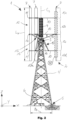
- Figure 1 shows a schematic perspective view of a vertical wind turbine 1 according to the invention.
- the vertical wind turbine 1 extends along a longitudinal direction X, a transverse direction Y and a height direction Z, which together form a Cartesian coordinate system.
- the vertical wind turbine 1 comprises a rotor 2, a machine house 3, a tower system 4, foundations 5 and a container-like control cabinet 6.
- the rotor 2 comprises a plurality of vertical blades 7, which are attached to a rotor hub 9 via a blade suspension 8, which is mounted in the machine house 3 so as to be rotatable about a vertically aligned rotor rotation axis C 2 , i.e. parallel to the height direction Z.
- the blade suspension 8 comprises rotor arms 10, which extend between the blades 7 and the rotor hub 9.
- a signal and/or measuring mast 11 is arranged on the rotor hub 9 concentrically to the rotor rotation axis C 2 .
- the machine house 3 is usually located at the top of the tower system 4, is soundproofed and contains a drive train (generator, rotor bearing, gearbox, mechanical brake as well as cooling and lubrication system, see Fig.7 ) of the vertical wind turbine 1.
- the tower system 4 is preferably designed as Lattice mast tower.
- the foundations 5 are preferably concrete foundations, which take the load of the tower system 4 including the machine house 3 and rotor 2.
- Other components, such as electrical converters, switching components and a control device (see Fig. 11 ) of the vertical wind turbine 1 are preferably accommodated in the control cabinet 6.
- the blades 7 are mounted so as to be rotatable about a blade rotation axis C 7 , which also runs essentially parallel to the height direction Z. In order to rotate the blades 7 about their respective blade rotation axis C 7, they are each provided with at least one pitch drive 12. At least one of the rotor arms 10 is connected to the pitch drive 12, which can thus help to absorb a load of the blade 7.
- Fig. 2 shows the vertical wind turbine 1 in a schematic front view.
- the blades 7 comprise several blade sections 13, namely an upper end section 13a, an upper middle section 13b, a lower middle section 13c and a lower end section 13d.
- the pitch drive 12 is arranged between the upper middle section 13b and the lower middle section 13c.
- An additional bearing point 14 is provided between the upper end section 13a and the middle end section 13b and between the lower middle section 13c and the lower end section 13d.
- the blades 7 are each connected to the rotor hub 9 by one of the arms 10, which is designed only to transmit forces acting radially to the rotor rotation axis C 2 , which consequently act essentially in a horizontal plane spanned parallel to the longitudinal direction X and transverse direction Y. Since the lower of the arms 10 are located in the area of the lower middle section 13c and the lower end section 13d in the height direction Z below the machine house 3 at the level of the tower system 4, the arms 10 are connected there to the rotor hub 9 via a transverse suspension 15.
- the transverse suspension 15 comprises a plurality of transverse struts 16 which are connected to and hold the arms 10 and the transverse connecting element 10a between the arms 10 and a transverse connecting element 10a.
- a support structure 17 is designed to absorb the weight load of the rotor 2.
- the support structure 17 comprises cross struts 15 which support the arms 10 attached to the pitch drive 12 by transferring loads below the arms 10 to them at a lower end section of the rotor hub 9.
- Fig. 2 shows that the rotor hub 9 and the tower system 4 are each designed as a lattice tube structure.
- the tower system 4 which is designed as a lattice tower, it tapers towards the machine house 3 and there absorbs all the static and dynamic loads caused by the rotor 2.
- the loads are introduced into the ground via the foundations 5.
- the machine house 3 is accessible via a ladder (not shown) which will not be discussed further.
- a maximum width b 4 of the tower system 4 at the foundations 5 measured parallel to the longitudinal direction X is, for example, 22 m.
- a length L 7 of the blades 7 measured parallel to the height direction Z is, for example, 54 m.
- a total height of the vertical wind turbine 1 measured including a height of the foundations projecting above the ground is, for example, 105 m without signal and/or measuring mast 11 and, for example, 110 m with signal and/or measuring mast 11.
- Fig. 3 shows the vertical wind turbine 1 in a schematic plan view.
- the blades 7 have a blade profile and move on a circular path K around the rotor rotation axis C 2.
- a diameter D K circular path K is, for example, 32 m and corresponds approximately to a maximum diameter of the tower system 4.
- the arms 10 have two struts 18 at their proximal end, the ends of which are connected to the rotor hub 9 at a horizontal distance from one another. At their distal end, the arms 10 are combined to form a single strut 18. At a connection point 19, the struts 18 leading to the proximal end are connected to the to the distal end, to which the pitch drive 12 is attached, are brought together in a fork-like manner. Furthermore, the cross-connecting element 10a of the cross suspension 15 is formed from three struts 18 connected to one another at their ends, which in a projection along the height direction Z form an isosceles triangle that lies in a plane running parallel to the longitudinal direction X and transverse direction Y.
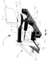
- Fig. 4 one in Fig. 2 marked detail IV of one of the blades 7 of the vertical wind turbine 1.
- the blade 7 has blades 19, each of which is attached to a spar 20 and is arranged concentrically to the blade rotation axis C 7.
- the blade 7 is mounted in a bearing unit 21 so that it can rotate about the blade axis C 7.
- the bearing unit 21 comprises a bearing housing 22 in which two roller bearings 23 are arranged, which engage around a bearing shaft 24 of the bearing unit 21, which is designed as a hollow shaft.
- the wing 7 is mounted in the pitch drive 12 on a motor shaft 25 of the pitch drive 12.
- the spars 20 form a wing axis 26 that runs through the wing 7 over its entire length, to which the wing blades 19 are firmly connected and held so that they can rotate.
- the wing blades 19 can be made in a shell construction and attached to the spar 20.
- the wing blades 19 have an outer skin to absorb torsional forces, a spar flange to absorb bending moments, a spar web as well as ribs and stringers to prevent the outer skin from undulating or buckling (see Fig. 5 ).
- Fig. 5 shows a in Fig. 4 marked detail V of the wing 7 with the pitch drive 12 in a schematic cross-sectional view along the wing rotation axis C 7 .
- the pitch drive 12 has a pitch motor 27 which is arranged in a gap 28 between the upper middle section 13b and the lower middle section 13c of the wing 7.
- the pitch motor 27 is designed as an electronically controlled gearless air-cooled torque motor and has a stator ring 29 and a rotor ring 30 which surrounds the stator ring 29 on the circumference and is spaced apart from it by a gap.
- a heat sink 31 with cooling fins 32 is attached to an outer peripheral surface of the stator ring 29 in order to be able to dissipate waste heat from the pitch motor 27.
- the rotor ring 30 of the pitch motor 27 is mounted on two disk-shaped rims 33, which connect the rotor ring 30 to the essentially cylindrical motor shaft 25 in a rotationally fixed manner via a clamping set 34.
- a motor housing 35 of the pitch motor 27 forms a motor interior 36 in which the rotor ring 30 is accommodated.
- the motor housing 35 has a cover 37 and a base 38 which extend in a disc shape along and essentially parallel to the rims 33.
- the cover 37 and base 38 are each connected to a bearing seat 39.
- the cover 37 and base 38 are connected to the stator ring 29 and heat sink 31 and, on a side of the pitch motor 27 facing the strut 18 carrying the blade 7, to a motor flange 40 of the pitch drive 12.
- the motor flange 40 forms end faces 41, at which the strut 18 is connected to the motor flange 40 via a suspension flange 42 attached to the strut 18.
- the suspension flange 42 forms a counter end face 43, which points radially away from the rotor rotation axis C 2 in the direction of the circular path K of the blades 7.
- the motor flange 40 and suspension flange 42 are connected to one another by means of connecting elements 44, which are preferably designed as detachable connecting elements 44, such as screw-bolt connections.
- a free space 40a is arranged between the end faces 41 of the motor flange 40 in order to provide sufficient space for heat dissipation in the area of the cooling fins 32 or to prevent heat build-up.
- Stiffening lamellae 45 extend between the bearing seat 39 and the motor flange 40 in order to be able to transfer the static and dynamic loads emanating from the blade 7, which are transmitted from the bearing seat 39 via the motor housing 35 to the motor flange 40, to the motor flange 40 as far as possible without twisting the motor housing 35.
- support lamellae 46 are provided which extend radially from the annular bearing seat 39 outwards along the ceiling 37 and base 38 in order to stiffen them and prevent twisting of the motor housing 35.
- Stiffening slats 45 and support slats 46 are each advantageously connected in one piece, for example by welding, to the ceiling 37, base 38, bearing seat 39 and motor flange 40 or ceiling 37, base 38 and bearing seat 39, whereby they extend in and opposite to the height direction Z away from the ceiling 37 and base 38 in a web-like manner.
- the stiffening slats 45 and support slats 46 also contribute to cooling the pitch motor 37 by dissipating heat via the motor housing 35.
- a motor bearing 47 is arranged between each of the two bearing seats 39 and the motor shaft 25.
- the motor bearings 47 are designed as spherical roller bearings, for example. They transfer high radial forces from the blades 7 to the struts 18 of the rotor arms 10 and also stiffen the entire rotor 2.
- the motor bearings 47 are each accommodated in a bearing receiving space 48, which is largely hermetically sealed by sealing elements 49.
- the sealing elements 49 seal the bearing receiving space 48 both from the motor interior 36 and from the surroundings of the vertical wind turbine 1.
- the bearing receiving space 48 is closed off from the motor interior 36 by inner rings 50 which, in the axial direction of the blade 7 in or against the height direction Z, delimit the bearing receiving space 48 from the motor interior 36, resting on the motor bearing 47 and on the outer circumference of the sealing element 49.
- the bearing receiving space 48 is closed off from the surroundings of the vertical wind turbine 1 by outer rings 41 which rest on the bearing seat 39 on the outside and enclose the sealing element 49 on the inner circumference.
- the motor shaft 25 is connected to a transition section 52 or merges into it in one piece.
- the transition section 52 tapers away from the pitch drive 12 and is accommodated in a blade axis section 53, which connects the transition section 52 in an adapter-like manner to ribs 54 of the blades 7 extending transversely to the blade rotation axis C 7 in a rotationally fixed manner.
- connecting ends 55 of the transition section 52 pointing in the direction along the blade rotation axis C 7 are accommodated in fixing elements 56, which enclose the connecting ends 55 at least in a force-fitting manner and radially away from the connecting ends 55
- Flange sections 57 on which form-locking elements 58 and further connecting elements 59, for example also detachable in the form of screw-bolt connections, are provided, which produce a form-locking and/or force-locking connection between the fixing elements 56 and the respective rib 54.
- transition section 52 and spar 20 run coaxially to one another.
- the spar 20 surrounds the blade axis section 53, which in turn surrounds the transition section 52.
- the ribs 54 are attached to the spar 20 in a rotationally fixed manner and carry an outer skin 60 of the wing 7.
- Fig. 6 shows a schematic perspective view of the pitch drive 12, in which the pitch motor 27 is provided with an aerodynamic cover in the form of a casing 61.
- the casing 61 has an upper shell 62 and a lower shell 63, which enclose the pitch motor 27 in the area of the ceiling 37 and the base 38 like a hood and therefore cover the ceiling 37 and the base 38 together with the stiffener 45 and the support slats 46, whereby a drive gap 64 formed between the pitch drive 12 and the blade 7 and thus pressure losses and associated yield losses occurring therein are kept as low as possible.
- annular gap-shaped cooling opening 65 is formed, which axially encloses the heat sink 31 and through which the cooling fins 32 are exposed so that they can be unhindered by ambient air flowing around them and dissipate the waste heat of the pitch motor 27 to the environment of the vertical wind turbine 1.
- the drive gap 64 is further reduced by the casing 61 forming an extension 66 shaped according to aerodynamic aspects, which adjoins the upper shell 62 and lower shell 63 and whose outer contour in a projection along the blade rotation axis C 7 essentially corresponds to a blade profile of the blades 7.
- the casing 61 forms end pieces 67 which lie flush against the motor flange 40, the outer diameter of which is at least partially adapted to an outer diameter of the suspension flange 42.
- An outer contour of the suspension flange 42 is in turn adapted to an outer contour of the strut 18. End pieces 67, motor flange 40, connecting flange 42 and strut 18 thus extend with largely aligned Outer contours merge into one another and there is an aerodynamically advantageous transition between the pitch drive 12 and the wing suspension 8.
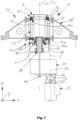
- Fig. 7 shows a schematic cross-sectional view of a drive train 70 of the vertical wind turbine 1 along a drive shaft 71 of the drive train 70, the drive axis of rotation C 71 of which runs coaxially to the rotor axis of rotation C 2.
- the rotor hub 9 has a base 72 which forms a pin 73 which also runs coaxially to the drive axis of rotation C 71 and the rotor axis of rotation C 2.
- a hub shoulder 74 pointing opposite to the height direction Z is formed on the base 72, which rests on a transition ring 75, which in turn rests axially opposite to the height direction Z on a first rotor bearing 76a forming part of a rotor bearing 76.
- the rotor bearing 76 also comprises a second rotor bearing 76b and a third rotor bearing 76c.
- the first and second rotor bearings 76a, 76b are designed, for example, as preloaded tapered roller bearings and transmit radial forces resulting from wind loads into the tower system 4.
- the first and second rotor bearings 76a, 76b are clamped onto a rotor shaft 78 by a separate bearing bush 77.
- the part of the rotor bearing 76 comprising the first and second rotor bearings 76a, 76b is joined axially freely floating into a hub connection 79 forming a machine support and thus remains free of vertical loads.
- the third rotor bearing 76c absorbs the vertical loads of the rotor 2 and thus essentially its weight and is advantageously designed as an axial spherical roller bearing that introduces the vertical loads directly into the machine house 3.
- a gearbox 81 of the vertical wind turbine 1 is arranged below the machine house 3, in which a rotor speed of the rotor shaft 78 is converted into a generator speed on an output shaft 82 of the gearbox 81.
- a coupling device 83 for example in the form of a double-Catalan, torsionally rigid steel disc coupling, connects the output shaft 82 in a torque-transmitting manner to a generator shaft 84 of a generator 85, for example a synchronous machine with permanent magnets, for generating electrical current, in this case for example with a maximum output of 750 kW.
- the coupling device 83 prevents the bearing forces from being over-determined.
- the rotor shaft 78 is provided with a predetermined breaking point 86 to limit the torque. (e.g. nominal torque 500 kNm; breaking torque 1000 kNm; permissible gear peak torque 1500 kNm).
- the gear 81 converts the low rotor speed according to the invention into a high generator speed.
- a gear ratio factor i is, for example, around 75.
- a gear housing 87 of the gear 81 is rigidly bolted to the hub connection via a flange bell 88. In this way, the high operating torque is fed back directly.
- a pitch tube 90 runs coaxially to the rotor shaft 78 through the gear 81 and serves to guide control and power cables for the pitch drive 12.
- the pitch tube 12 is driven in the coupling 89 above the predetermined breaking point 86 by being connected to the rotor 2 in a rotationally fixed manner.
- Fig. 8 shows a schematic perspective view of a first embodiment of the hub connection 80 of the vertical wind turbine 1 according to the invention.
- the hub connection 80 comprises a cylindrical, drum-like, integrally formed base body 91, which has a passage 92 for receiving a shaft bearing unit 93 (see Fig. 7 ) of the drive train 70.
- Support feet 94 are attached to the base body 91 at equal distances on the outer circumference and extend radially away from it.
- the support feet 94 each form a horizontally aligned support 95 for mounting the hub connection 80 on the tower system 4.
- the support feet 94 can, for example, be welded together from sheet metal and connected in one piece to the base body 91 by welding or flanged to it, which in turn can also be welded together from sheet metal.
- Fig. 9 shows a schematic perspective view of a second embodiment of a hub connection 80' according to the invention.
- the hub connection 80' is formed from a plurality of uniform segments 96, each of which provides two flange ends 97, to which they are connected to one another to form a circle and thus together form a passage 92' for receiving the shaft bearing unit 93.
- Each of the segments 96 forms a support arm 98.
- a vertically running support bracket 99 is formed, which is designed to be mounted on the tower system 4 while lying in a respective radial plane.
- the segments 96 can be cast individually, which can help to reduce manufacturing costs, particularly in series production, and also to adapt the material thickness of the segments 96 to highly stressed areas and to provide roundings to reduce notch effects, for example by the flange ends 97 merging into the support arms 98 to form an arc profile.
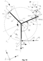
- Fig. 10 shows a schematic top view of the vertical wind turbine 1 to illustrate angular positions and force relationships on the blades 7 during operation of the vertical wind turbine 1.
- the blades 7 are hit by the wind at a wind speed vw.
- the rotation of the rotor 2 about the rotor rotation axis C 2 results in an angular speed ⁇ of the rotor 2, which, multiplied by a radius R K of the circular path K corresponding to half the diameter D K of the circular path K, results in a circumferential speed v U of the blades 7 along the circular path K according to equation (1) below:
- v U ⁇ ⁇ R K
- the angle of attack ⁇ is measured between the vector of the circumferential speed v U and a profile chord 100 of the blades 7, which runs in a straight line between a leading edge 101 and a trailing edge 102.
- the pitch angle ⁇ is measured between the vector of the relative speed v R and the profile chord 100.
- the blades 7 have a symmetrical blade profile, whereby the blade chord forms a plane of symmetry of the blades 7 or their blade.
- the relative speed v R is a function of an azimuth angle ⁇ of the rotor 2, which is measured, for example, for the respective rotor arm 10 starting from a zero point at a position at 90° to the wind direction facing the wind, rotating relative to a main axis of the vertical wind turbine 1.
- a tangent of the angle of attack ⁇ is calculated as a function of wind speed vw, relative speed v R and azimuth angle ⁇ or a tip speed ratio A and azimuth angle ⁇ according to equation (4) below:
- the tip speed ratio ⁇ in turn corresponds to a ratio of circumferential speed vu to wind speed vw according to equation (5) below and is to be adjusted as optimally as possible and kept constant by the respective pitch drive 12 or its pitch motor 27 according to the respective wind conditions at varying pitch angles ⁇ in order to maximize an energy yield or a crop yield of a vertical wind turbine 1 according to the invention:
- ⁇ v U v W
- a static center of gravity of the blade 7 is located on the rotor rotation axis C 7 as far as possible.
- the rotor rotation axis C 7 is arranged at 20 to 23%, preferably 21.5% of a rotor blade depth measured from the leading edge 101 on the profile chord 100.
- a counterweight 103 is arranged in the area of the leading edge 101. arranged in the wing 7.
- the counterweight 103 is formed, for example, from rod segments, preferably a round steel rod with diameters between 60 and 100 mm, most preferably 80 mm.
- the rod segments are attached to the ribs 54.
- the segments can advantageously be connected to one another in an electrically conductive manner.
- the counterweight 103 can thus fulfill a dual function in that it also serves as a lightning conductor.
- the vertical wind turbine 1 has at least one wind speed sensor 104 and/or wind direction sensor 105.
- the wind speed sensor 104 and/or wind direction sensor 105 is arranged at the upper end of the signal and/or measuring mast 11 and/or on at least one of the blades 7 or on all of the blades 7.
- the wind speed sensor 104 and/or wind direction sensor 105 is preferably attached to the blade 7 in the area of the pitch drive 12 because wind speeds and/or directions measured there are highly relevant for controlling the pitch drive 12.
- the wind speed sensor 104 and/or wind direction sensor 105 is arranged at the distal end of a rod 106 attached to the blade 7 or pitch drive 12, which rod protrudes radially from the rotor rotation axis C 2 beyond the circular path K into an area in the vicinity of the vertical wind turbine 1, which lies as far as possible outside of air flow boundary layers formed around the rotor 2 and its components, i.e. largely outside the area of influence of the blade 7s.
- Fig. 11 shows a schematic diagram to illustrate the functioning of a control device 107 according to the invention of the vertical wind turbine 1.
- the control device 107 comprises a supply unit 108, which is connected on the one hand to a motor control unit 109, which contains a power section 110, and on the other hand to a choke 111 and a filter 112 in order to ensure a power supply that is as free from interference and errors as possible.
- the power unit 110 is designed, for example, as an inverter.
- the motor control unit 109 is connected to the pitch drive 12, a Energy supply device 114 and a control unit 115 for monitoring and controlling the vertical wind turbine 1.
- the energy supply device 114 comprises a main energy supply unit 116 and an auxiliary energy supply unit 117, the latter for example providing emergency energy to the control device 107 if the main energy supply unit 116 fails or is not available.
- the control device 107 comprises a motor protection unit 118 and a data transmission unit 119.
- the pitch drive 12 further comprises a rotary encoder 120 with a position sensor 121 for monitoring a rotational position of the rotor ring 30 relative to the stator ring 29.
- the pitch motor 27 further comprises a motor unit 122, which contains at least the stator ring 29 and the rotor ring 30, and a temperature measuring unit 123, which has a first temperature sensor 124 and at least one further temperature sensor 125.
- the first temperature sensor 124 is designed, for example, as a resistance-dependent temperature sensor (KTY), whereas the further temperature sensor 125 is designed, for example, as a temperature sensor with positive temperature coefficients (PTC).
- KTY resistance-dependent temperature sensor
- PTC positive temperature coefficients
- the power section 110 of the motor control unit 109 of the control device 107 permanently converts a current required to drive the pitch motor 27.
- the power section 110 can deliver a current of 100 to 200, preferably 150 A RMS , and provide a peak current of 200 to 250, preferably 210 A RMS , so that a maximum torque of the pitch motor 27 can be called up in the short term.
- the control unit 115 cyclically calculates a target value S for the adjustment of each of the blades 7, for example as a target pitch angle ⁇ S , and makes this available to the motor control unit 109 via the corresponding line 113.
- an actual value I for example an actual pitch angle ⁇ I
- the motor control unit 109 determines a difference value d, for example an angle deviation ⁇ , from the setpoint S and the actual value I and derives a control value U from this, for example in the form of a control current A, which is transmitted to the respective drive unit 12 or the motor unit 122 of the pitch motor 27.
- the motor control unit 109 controls the pitch angle ⁇ with the smallest possible angular deviation ⁇ .
- the temperature measuring unit 123 uses the temperature sensor 124 and the further temperature sensor 125 to record a first temperature measurement value T or at least one further temperature measurement value T x , which are determined for redundancy reasons and/or for different uses.
- the temperature measurement value T is transmitted via one of the lines 113 to the motor protection unit 118.
- the motor protection unit 118 compares the temperature measurement value T with a temperature limit value and, if the temperature limit value is exceeded, can transmit an alarm signal to the motor control unit 109 via the corresponding line 113, where measures to protect the respective pitch drive 12, such as an emergency shutdown or interruption of the power supply, are initiated.
- the motor protection unit 118 can transmit temperature values to the data transmission unit 119 via the corresponding line 113 for forwarding temperature data to the motor control unit 109 and/or control unit 115.
- the additional temperature measurement value T x is transmitted directly to the motor control unit 109 via corresponding lines 113 in order to keep the temperature of the drive unit 12 or its components within the scope of a planned or prescribed operating temperature. Temperature control measures can be initiated immediately in the motor control unit 109, whereas longer-term temperature control measures can be carried out in the control unit 115. Thus, with the help of the alarm signal emitted by the motor protection unit 118 on the basis of the temperature measurement value T, short-term temperature control is provided to protect the drive unit 12, whereas long-term temperature control is possible via the temperature data forwarded to the control unit 115 and medium-term temperature control is possible via the direct forwarding of the additional temperature measurement value T x to the motor control unit 109.
- Fig. 12 shows a schematic diagram of an example torque characteristic curve of the pitch motor 27.
- the diagram shows a maximum torque Tp, a nominal torque Ti and continuous torque Tc of the pitch motor 27 over the speed of the pitch motor 27.
- the maximum torque Tp can be made available by the pitch motor 27 for a short time in order to cause a rapid adjustment of the respective blade 7 spontaneously, i.e. within a very short, very limited time period. If the maximum torque Tp is exceeded, i.e. in the event of an overload, the motor slips and is therefore intrinsically safe, i.e. no damage occurs to the motor.
- the nominal torque Ti can be called up permanently until a temperature limit is exceeded.
- the continuous torque Tc is generally available permanently and does not lead to any temperature limit being exceeded.
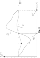
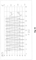
- Fig. 13 shows a schematic diagram with exemplary cam disks for controlling the pitch motor 12, namely a first cam disk S1, which is provided for the nominal wind speed v 2 of, for example, 12 m/s, and a further cam disk S2, which is provided for the first cut-off wind speed v 3 of, for example, 20 m/s. Between these two wind speeds, a nominal or full load operation of the vertical wind turbine 1 is provided according to the seventh operating mode M7, in which the rotor 2 rotates at a nominal speed and the generator 85 delivers its nominal power.
- the setpoint S of the pitch angle ⁇ is shown as the setpoint pitch angle ⁇ s as a function of the azimuth angle ⁇ .
- the target pitch angle ⁇ s at an azimuth angle ⁇ of 0° is less than 0°, approximately in the range of -2 to -3°.
- the target pitch angle ⁇ s first passes through a local maximum of -2 to -3° at an azimuth angle ⁇ of approx. 20° and then a turning point between -3 and -4° at an azimuth angle ⁇ of approx. 20° until the target pitch angle ⁇ s reaches an absolute minimum of approx. -10° at an azimuth angle O of approx. 50°.
- the target pitch angle ⁇ s for the nominal wind speed v 2 is again at approx. 2 to -3° and then reaches a value of 0° at an azimuth angle ⁇ of approx. 200°.
- the target pitch angle ⁇ S for the nominal wind speed v 2 reaches its absolute maximum of approx. 2 to 3° and then reaches a value of 0° again at an azimuth angle O of approx. 290° and at about the same time a turning point.
- the target pitch angle ⁇ s passes through a local minimum of approximately -3 to -4° at an azimuth angle O of approximately 330° and finally reaches its initial range of -2 to -3° again at an azimuth angle O of approximately 360°.
- the target pitch angle ⁇ S at an azimuth angle O of 0° is less than 0°, approximately in the range of -1 to -2°, and is thus smaller than the target pitch angle ⁇ s at an azimuth angle O of 0° at nominal wind speed v 2 .
- the target pitch angle ⁇ s passes through a turning point between -14 and -16° at an azimuth angle ⁇ of approx. 45° without a local maximum until the target pitch angle ⁇ s reaches another turning point at approx. -30° at an azimuth angle O of approx. 100° and then an absolute minimum of approx. -37° to -38° at an azimuth angle ⁇ of approx. 100°.
- the target pitch angle ⁇ S for the first cut-off wind speed v 3 is similar to the target pitch angle ⁇ S for the nominal wind speed v 2 at approx. -2 to -3° and then reaches a value of 0° at an azimuth angle ⁇ of approx. 170° earlier than the target pitch angle ⁇ S for the nominal wind speed v 2.
- the target pitch angle ⁇ S reaches its absolute maximum of approx. 35° and then reaches a turning point of approx. 25° at an azimuth angle ⁇ of approx. 270°.
- the target pitch angle ⁇ s then passes through a turning point of approximately 15° at an azimuth angle O of approximately 320° and finally reaches its initial range of -1 to -2° again at an azimuth angle O of approximately 360°.
- Fig. 14 shows a schematic perspective view of a test bench 200 for determining a positioning error of the pitch motor 27 of the vertical wind turbine 1.
- the test bench 200 has a frame structure 201 to which a holding arm 202 for holding the pitch drive 12 or pitch motor 27 and a cross arm 203 are attached.
- the pitch drive 12 is mounted together with a section of the blade 7 via the motor flange 40 on the holding arm 202 of the test bench 200, similar to the rotor arm 10 of the vertical wind turbine 1.
- the transition section 52 protruding from the pitch motor 27 is accommodated in a shaft holder 204 of the test bench 200 so as to be rotatable about the blade rotation axis C 7 .
- the shaft holder 204 is arranged centrally on a pendulum arm 205, which is also rotatable about the wing rotation axis C 7 and is held on an extension 206 of the frame structure 201.
- a weight body 207 is held at each of the two ends of the pendulum arm 205 pointing away from the wing rotation axis C 7.
- the weight bodies 207 simulate a total mass of the wing 7.
- the ends of the pendulum arm 205 are connected to the cross arm 203 via spring elements 208 in the form of spiral spring packages and joint devices 209 attached to them.
- the spring elements 208 simulate wind forces.
- Fig. 15 shows a schematic diagram of a device constructed using the Fig. 14
- the positioning error determined by the test bench 200 shown in the form of an angular deviation ⁇ of the pitch motor 27 in ° over time t in seconds for a large number of control cycles during which a simulated azimuth angle ⁇ undergoes a rotor rotation of 360°.
- the angular deviation ⁇ reaches a value of less than 1.5° for target pitch angles ⁇ s which are at most 30 to 40°.
- Fig. 16 shows a schematic diagram of a positioning error of the pitch motor 27 in the form of the angular deviation ⁇ in ° over the time t in seconds over a control cycle for the nominal wind speed v 2 .
- the angular deviation ⁇ is always below 0.5° in terms of amount and reaches a maximum of approx. 0.25° in terms of amount after local and absolute minima and maxima of the target pitch angle ⁇ S .
- the angular deviation ⁇ moves around 0°.
- Fig. 17 shows a schematic diagram of a positioning error of the pitch motor 27 in the form of the angular deviation ⁇ in ° over the time t in seconds over a control cycle for the first cut-off wind speed v 3 .
- the angular deviation ⁇ is always below 1.5° in terms of amount and reaches a maximum of approx. 1.45° in terms of amount after local and absolute minima and a maximum of approx. 0.6 in terms of amount at local and absolute maxima of the target pitch angle ⁇ S .
- the angular deviation ⁇ also moves around 0°.
- the angular deviation ⁇ at the first cut-off wind speed v 3 is therefore slightly higher than at the nominal wind speed v 2 .
- more than two pitch drives 12 per wing 7 or, for example, one pitch drive 12 per wing section 13 can be provided.
- two wings 7 or wing sections 13 driven vertically separately from one another can be provided.
- two pitch drives 12 can be arranged between two wings 7 or wing sections 13 and assigned as upper and lower pitch drives 12 to an upper or lower of the two wings 7 or wing sections 13, respectively.
- the upper wing or wing section 13 can thus be rotated independently of the lower wing 7 or wing section 13 about its respective wing rotation axis C 7 .
- Each of the two blades 7 or blade sections 13 can be assigned at least one wind speed 104 and/or wind direction sensor 105.
- the at least one wind speed 104 and/or wind direction sensor 105 is advantageously arranged centrally on the respective blade 7 or blade section 13 and can be attached there to a rod 106 as described above.
- optimal pitch angles ⁇ can be set separately for each of the blades 7 or blade sections 13 arranged vertically one above the other in order to take into account changing wind flow conditions in the height direction Z along the blade 7 when operating the vertical wind turbine 1 and thus further increase its efficiency.
- This is to be considered in particular for circular path diameters D K that are greater than 32 m and are, for example, 45 m, whereby a total length L 7 of the blades 7 would then be, for example, approximately 73 m.
Landscapes
- Engineering & Computer Science (AREA)
- Life Sciences & Earth Sciences (AREA)
- Sustainable Development (AREA)
- Sustainable Energy (AREA)
- Chemical & Material Sciences (AREA)
- Combustion & Propulsion (AREA)
- Mechanical Engineering (AREA)
- General Engineering & Computer Science (AREA)
- Wind Motors (AREA)
Claims (15)
- Éolienne verticale (1) avec une pluralité d'ailettes verticales (7), qui sont fixées indépendamment les unes des autres sur un axe d'ailette vertical (26) et peuvent tourner autour d'un axe de rotation d'ailette respectif (C7) et sont montées rotatives sur une trajectoire circulaire commune (K) autour d'un axe de rotation de rotor vertical (C2), caractérisée en ce que
l'éolienne verticale (1) est conçue pour réguler un angle de pas (β) des pales (7) au moins (a.) dans un mode de charge partielle de l'éolienne verticale (1) de telle sorte que les pales (7) tournent avec un nombre de tours rapides (λ) sensiblement constant et (b.) dans un mode de fonctionnement nominal de l'éolienne verticale (1) de telle sorte que les pales (7) tournent avec un nombre de tours rapides (λ) variable. - Éolienne verticale (1) selon la revendication 1, caractérisée en ce que l'éolienne verticale (1) est conçue pour fonctionner en mode de charge partielle dans une plage de vitesses du vent qui se situe au moins par sections entre 3 et 12 m/s.
- Éolienne verticale (1) selon la revendication 1 ou 2, caractérisée en ce que le nombre constant de cycles rapides (λ) est compris entre 2 et 2.6, de préférence entre 2.2 et 2.4, de manière très préférée sensiblement 2.3.
- Éolienne verticale (1) selon au moins l'une des revendications 1 à 3, caractérisée en ce que le mode de fonctionnement nominal correspond à un fonctionnement à pleine charge avec une vitesse de rotation nominale du rotor à des vitesses de vent supérieures à la vitesse de vent nominale (v2) et inférieures à la première vitesse de vent de coupure (v3) ou à une autre vitesse de vent de coupure (v4).
- Éolienne verticale (1) selon la revendication 4, caractérisée en ce que l'éolienne verticale (1) est conçue pour réguler l'angle de pas (β) de telle sorte que les pales (7) tournent à une vitesse nominale sensiblement constante en mode de fonctionnement nominal.
- Éolienne verticale (1) selon la revendication 4 ou jusqu'à la revendication 5, caractérisée en ce que, pour une première vitesse de vent de coupure v3 de l'éolienne verticale, le coefficient de vitesse variable λ est compris entre 1 et 1.8, de préférence entre 1.3 et 1.5, de manière très préférée sensiblement égale à 1.38.
- Éolienne verticale (1) selon au moins l'une des revendications 1 à 6, caractérisée en ce que l'éolienne verticale (1) est conçue pour réguler l'angle de pas (β) dans un mode de démarrage de telle sorte que les pales (7) passent d'une course de résistance avec des nombres de course rapide λ ≤ 1 à une course rapide avec des nombres de course rapide λ > 1.
- Éolienne verticale (1) selon au moins l'une des revendications 1 à 7, caractérisée en ce que la régulation de l'angle de pas (β) est basée sur au moins une came (S1, S2) qui détermine l'angle de pas (β) sensiblement en continu pour une rotation totale du rotor (2).
- Éolienne verticale (1) selon au moins l'une des revendications 1 à 8, caractérisée en ce qu'une valeur maximale de l'angle de pas (7) est généralement plus grande pour les positions côté vent de l'aile (7) que pour les positions côté vide de l'aile (7) respectivement par rapport à l'axe de rotation du rotor (C2).
- Éolienne verticale (1) selon au moins l'une des revendications 1 à 9, caractérisée en ce que pour des vitesses de vent dans la plage d'une vitesse de vent nominale (v2) de l'éolienne verticale (1), l'angle de pas (β) est inférieur à zéro pour un angle d'azimut (O) de 0° mesuré à partir d'une ligne zéro perpendiculaire à la direction du vent.
- Éolienne verticale (1) selon au moins l'une des revendications 1 à 10, caractérisée en ce qu'il existe un maximum local de l'angle de pas (β) au moins pour des vitesses de vent dans la plage de la vitesse de vent nominale (v2) avec un angle d'azimut (O) mesuré à partir d'une ligne zéro perpendiculaire à la direction du vent de 0° à 90°.
- Éolienne verticale (1) selon au moins l'une des revendications 1 à 11, caractérisée par au moins un capteur de vitesse du vent (104) et/ou au moins un capteur de direction du vent (105), qui est disposé sur au moins l'une des pales (7) et est relié par transmission de signal à un dispositif de commande (107) pour déterminer une valeur de consigne (S) de l'angle de pas (β).
- Éolienne verticale (1) selon au moins l'une des revendications 1 à 12, caractérisée en ce que, pour des vitesses de vent allant de l'absence de vent jusqu'à une autre vitesse d'arrêt (v4) de l'éolienne verticale (1), une valeur d'une erreur de positionnement (δ) lors de la régulation de l'angle de pas (β) est essentiellement toujours inférieure à 5°, de préférence inférieure à 3°, très préférablement inférieure à 1,5°.
- Kit pour éolienne verticale (1) selon au moins l'une quelconque des revendications 1 à 13.
- Procédé pour faire fonctionner une éolienne verticale (1), dans lequel des angles de pas (β) sont prédéfinis autour d'un axe vertical respectif (26) des pales verticales (7) de l'éolienne verticale (1), caractérisé en ce que les angles de pas (β) sont réglés au moins (a.) dans un mode de charge partielle de l'éolienne verticale (1) de telle sorte que les pales (7) tournent avec un nombre de rotation rapide (λ) sensiblement constant, et (b.) dans un mode de fonctionnement nominal de l'éolienne verticale (1) de telle sorte que les pales (7) tournent avec un nombre de rotation rapide (λ) variable.
Applications Claiming Priority (1)
| Application Number | Priority Date | Filing Date | Title |
|---|---|---|---|
| PCT/IB2017/053972 WO2019002922A1 (fr) | 2017-06-30 | 2017-06-30 | Installation éolienne verticale avec vitesse de rotation en bout de pale contrôlée ainsi que kit de construction pour celle-ci et procédé pour son fonctionnement |
Publications (3)
| Publication Number | Publication Date |
|---|---|
| EP3645868A1 EP3645868A1 (fr) | 2020-05-06 |
| EP3645868B1 true EP3645868B1 (fr) | 2024-10-23 |
| EP3645868C0 EP3645868C0 (fr) | 2024-10-23 |
Family
ID=59506309
Family Applications (1)
| Application Number | Title | Priority Date | Filing Date |
|---|---|---|---|
| EP17746540.8A Active EP3645868B1 (fr) | 2017-06-30 | 2017-06-30 | Installation éolienne verticale avec vitesse de rotation en bout de pale contrôlée ainsi que kit de construction pour celle-ci et procédé pour son fonctionnement |
Country Status (4)
| Country | Link |
|---|---|
| US (2) | US11434869B2 (fr) |
| EP (1) | EP3645868B1 (fr) |
| CN (1) | CN110892152A (fr) |
| WO (1) | WO2019002922A1 (fr) |
Families Citing this family (7)
| Publication number | Priority date | Publication date | Assignee | Title |
|---|---|---|---|---|
| WO2019002549A1 (fr) | 2017-06-30 | 2019-01-03 | Agile Wind Power Ag | Centrale éolienne verticale équipée d'un moteur de pas portant une pale de rotor et ensemble de pièces destinées à celle-ci et procédé de fonctionnement de celle-ci |
| ES2949536T3 (es) * | 2019-06-27 | 2023-09-29 | Vestas Wind Sys As | Control de potencia de salida de una turbina eólica a velocidad del viento por debajo de la nominal |
| JP7040792B2 (ja) * | 2019-10-15 | 2022-03-23 | 力也 阿部 | 揚力型垂直軸風水車 |
| CN111236691A (zh) * | 2020-03-26 | 2020-06-05 | 中邮建技术有限公司 | 一种快装式楼顶多功能支撑装置 |
| CN111622904B (zh) * | 2020-06-01 | 2022-02-01 | 安徽理工大学 | 对称翼型垂直轴风力机的变桨控制方法及系统 |
| DE102021204863A1 (de) * | 2021-05-12 | 2022-11-17 | Contitech Antriebssysteme Gmbh | Riemen |
| CN118583306B (zh) * | 2024-08-02 | 2024-09-27 | 胜利油田东强机电设备制造有限公司 | 一体化温度变送器 |
Citations (1)
| Publication number | Priority date | Publication date | Assignee | Title |
|---|---|---|---|---|
| US4430044A (en) * | 1981-11-23 | 1984-02-07 | Liljegren L Kenyon | Vertical axis wind turbine |
Family Cites Families (19)
| Publication number | Priority date | Publication date | Assignee | Title |
|---|---|---|---|---|
| US3902072A (en) | 1974-02-19 | 1975-08-26 | Paul J Quinn | Wind turbine |
| US4410806A (en) | 1981-09-03 | 1983-10-18 | Brulle Robert V | Control system for a vertical axis windmill |
| US4494007A (en) | 1982-09-02 | 1985-01-15 | Gaston Manufacturing, Inc. | Wind machine |
| US4609827A (en) | 1984-10-09 | 1986-09-02 | Nepple Richard E | Synchro-vane vertical axis wind powered generator |
| US5503525A (en) | 1992-08-12 | 1996-04-02 | The University Of Melbourne | Pitch-regulated vertical access wind turbine |
| US8186940B2 (en) * | 2007-09-05 | 2012-05-29 | General Electric Company | Ventilation arrangement |
| CH700332B1 (de) | 2008-01-04 | 2010-08-13 | Patrick Richter | Windkraftanlage. |
| US8193657B2 (en) * | 2008-04-15 | 2012-06-05 | Michael A. Paluszek | Vertical axis wind turbine using individual blade pitch and camber control integrated with matrix converter |
| KR20100070532A (ko) * | 2008-12-18 | 2010-06-28 | 서울대학교산학협력단 | 풍력 발전기 |
| US20120045329A1 (en) * | 2009-02-10 | 2012-02-23 | West Virginia University | Method for circulation controlled vertical axis and turbines |
| CN102116264A (zh) * | 2010-07-05 | 2011-07-06 | 杨寿生 | 一种可调攻角兆瓦级垂直轴风力发电机 |
| US8789274B2 (en) * | 2010-09-23 | 2014-07-29 | Northern Power Systems, Inc. | Method and system for servicing a horizontal-axis wind power unit |
| DK2520533T4 (da) * | 2011-05-05 | 2019-09-09 | Siemens Ag | Servicekran til en vindmølle |
| CN104736845B (zh) * | 2012-08-14 | 2017-11-14 | 维斯塔斯风力系统有限公司 | 用于风力涡轮机控制的部分负载降额 |
| CN202991352U (zh) * | 2012-11-16 | 2013-06-12 | 张宝贵 | 叶片自动调控的升阻结合型垂直轴风力发电机 |
| US20150192105A1 (en) * | 2014-01-09 | 2015-07-09 | Hing Kwok Dennis Chu | Rotors for extracting energy from wind and hydrokinetic sources |
| CH709743A2 (de) | 2014-06-06 | 2015-12-15 | Agile Wind Power Ag | Vertikale Windkraftanlage sowie Verfahren zum Betrieb einer solchen Anlage. |
| CN104314751B (zh) * | 2014-10-08 | 2017-04-19 | 莫海路 | 一种垂直轴风力机及具有其的风能船 |
| KR102485868B1 (ko) * | 2015-06-30 | 2023-01-06 | 베스타스 윈드 시스템스 에이/에스 | 풍력 터빈 부품을 이동시키기 위한 방법 및 풍력 터빈 부품을 이동시키기 위한 이송 시스템 |
-
2017
- 2017-06-30 CN CN201780092775.8A patent/CN110892152A/zh active Pending
- 2017-06-30 WO PCT/IB2017/053972 patent/WO2019002922A1/fr not_active Ceased
- 2017-06-30 EP EP17746540.8A patent/EP3645868B1/fr active Active
- 2017-06-30 US US16/625,876 patent/US11434869B2/en active Active
-
2022
- 2022-07-27 US US17/874,687 patent/US11982257B2/en active Active
Patent Citations (1)
| Publication number | Priority date | Publication date | Assignee | Title |
|---|---|---|---|---|
| US4430044A (en) * | 1981-11-23 | 1984-02-07 | Liljegren L Kenyon | Vertical axis wind turbine |
Also Published As
| Publication number | Publication date |
|---|---|
| CN110892152A (zh) | 2020-03-17 |
| US11434869B2 (en) | 2022-09-06 |
| US20230027223A1 (en) | 2023-01-26 |
| US20200149508A1 (en) | 2020-05-14 |
| US11982257B2 (en) | 2024-05-14 |
| EP3645868A1 (fr) | 2020-05-06 |
| WO2019002922A1 (fr) | 2019-01-03 |
| EP3645868C0 (fr) | 2024-10-23 |
Similar Documents
| Publication | Publication Date | Title |
|---|---|---|
| EP3645869B1 (fr) | Éolienne verticale présentant un moteur à pas coaxial ainsi que kit de montage pour celle-ci et procédé pour son fonctionnement | |
| EP3645870B1 (fr) | Centrale éolienne verticale équipée d'un moteur de pas portant une pale de rotor et ensemble de pièces destinées à celle-ci et procédé de fonctionnement de celle-ci | |
| EP3645868B1 (fr) | Installation éolienne verticale avec vitesse de rotation en bout de pale contrôlée ainsi que kit de construction pour celle-ci et procédé pour son fonctionnement | |
| EP3896278B1 (fr) | Éolienne verticale, ainsi que procédé de fonctionnement d'une telle éolienne | |
| EP2914844B1 (fr) | Procédé pour faire fonctionner une éolienne, éolienne et dispositif de commande pour une éolienne | |
| WO2008152083A1 (fr) | Éolienne | |
| DE102014203508A1 (de) | Rotorblattlageranordnung für eine Windenergieanlage | |
| WO2015032803A1 (fr) | Éolienne | |
| EP2570655B1 (fr) | Dispositif de réglage actif d'une pale de (petite) éolienne | |
| EP2951433B1 (fr) | Dispositif de commande pour un système de lacet d'éolienne | |
| DE102018113760B4 (de) | Rotorlagergehäuse und Windenergieanlage mit Rotorlagergehäuse | |
| EP2636892A2 (fr) | Installation éolienne et procédé de production d'énergie rotative par le vent | |
| US20250109737A1 (en) | Methods for lubricating a pitch bearing of a wind turbine | |
| EP3404256A1 (fr) | Dispositif d'ajustement des pales de rotor d'une installation génératrice d'énergie à flux | |
| RU2312249C2 (ru) | Способ управления ветроэнергетической установкой и устройство для его осуществления | |
| WO2011160688A1 (fr) | Éolienne | |
| WO2013005090A2 (fr) | Éolienne bohg (berto otilio hernandez gutierrez) pourvue d'un axe de rotation vertical pour corps de poussée aérodynamique, et d'une hélice aérienne de surface variable |
Legal Events
| Date | Code | Title | Description |
|---|---|---|---|
| STAA | Information on the status of an ep patent application or granted ep patent |
Free format text: STATUS: UNKNOWN |
|
| STAA | Information on the status of an ep patent application or granted ep patent |
Free format text: STATUS: THE INTERNATIONAL PUBLICATION HAS BEEN MADE |
|
| PUAI | Public reference made under article 153(3) epc to a published international application that has entered the european phase |
Free format text: ORIGINAL CODE: 0009012 |
|
| STAA | Information on the status of an ep patent application or granted ep patent |
Free format text: STATUS: REQUEST FOR EXAMINATION WAS MADE |
|
| 17P | Request for examination filed |
Effective date: 20200130 |
|
| AK | Designated contracting states |
Kind code of ref document: A1 Designated state(s): AL AT BE BG CH CY CZ DE DK EE ES FI FR GB GR HR HU IE IS IT LI LT LU LV MC MK MT NL NO PL PT RO RS SE SI SK SM TR |
|
| AX | Request for extension of the european patent |
Extension state: BA ME |
|
| DAV | Request for validation of the european patent (deleted) | ||
| DAX | Request for extension of the european patent (deleted) | ||
| STAA | Information on the status of an ep patent application or granted ep patent |
Free format text: STATUS: EXAMINATION IS IN PROGRESS |
|
| 17Q | First examination report despatched |
Effective date: 20220628 |
|
| RAP3 | Party data changed (applicant data changed or rights of an application transferred) |
Owner name: AGILE WIND POWER AG |
|
| P01 | Opt-out of the competence of the unified patent court (upc) registered |
Effective date: 20230317 |
|
| GRAP | Despatch of communication of intention to grant a patent |
Free format text: ORIGINAL CODE: EPIDOSNIGR1 |
|
| STAA | Information on the status of an ep patent application or granted ep patent |
Free format text: STATUS: GRANT OF PATENT IS INTENDED |
|
| INTG | Intention to grant announced |
Effective date: 20240528 |
|
| GRAS | Grant fee paid |
Free format text: ORIGINAL CODE: EPIDOSNIGR3 |
|
| GRAA | (expected) grant |
Free format text: ORIGINAL CODE: 0009210 |
|
| STAA | Information on the status of an ep patent application or granted ep patent |
Free format text: STATUS: THE PATENT HAS BEEN GRANTED |
|
| AK | Designated contracting states |
Kind code of ref document: B1 Designated state(s): AL AT BE BG CH CY CZ DE DK EE ES FI FR GB GR HR HU IE IS IT LI LT LU LV MC MK MT NL NO PL PT RO RS SE SI SK SM TR |
|
| REG | Reference to a national code |
Ref country code: GB Ref legal event code: FG4D Free format text: NOT ENGLISH |
|
| REG | Reference to a national code |
Ref country code: CH Ref legal event code: EP |
|
| REG | Reference to a national code |
Ref country code: DE Ref legal event code: R096 Ref document number: 502017016512 Country of ref document: DE |
|
| REG | Reference to a national code |
Ref country code: IE Ref legal event code: FG4D Free format text: LANGUAGE OF EP DOCUMENT: GERMAN |
|
| P04 | Withdrawal of opt-out of the competence of the unified patent court (upc) registered |
Free format text: CASE NUMBER: APP_61698/2024 Effective date: 20241118 |
|
| U01 | Request for unitary effect filed |
Effective date: 20241115 |
|
| U07 | Unitary effect registered |
Designated state(s): AT BE BG DE DK EE FI FR IT LT LU LV MT NL PT RO SE SI Effective date: 20241121 |
|
| PG25 | Lapsed in a contracting state [announced via postgrant information from national office to epo] |
Ref country code: IS Free format text: LAPSE BECAUSE OF FAILURE TO SUBMIT A TRANSLATION OF THE DESCRIPTION OR TO PAY THE FEE WITHIN THE PRESCRIBED TIME-LIMIT Effective date: 20250223 Ref country code: HR Free format text: LAPSE BECAUSE OF FAILURE TO SUBMIT A TRANSLATION OF THE DESCRIPTION OR TO PAY THE FEE WITHIN THE PRESCRIBED TIME-LIMIT Effective date: 20241023 |
|
| PG25 | Lapsed in a contracting state [announced via postgrant information from national office to epo] |
Ref country code: ES Free format text: LAPSE BECAUSE OF FAILURE TO SUBMIT A TRANSLATION OF THE DESCRIPTION OR TO PAY THE FEE WITHIN THE PRESCRIBED TIME-LIMIT Effective date: 20241023 |
|
| PG25 | Lapsed in a contracting state [announced via postgrant information from national office to epo] |
Ref country code: NO Free format text: LAPSE BECAUSE OF FAILURE TO SUBMIT A TRANSLATION OF THE DESCRIPTION OR TO PAY THE FEE WITHIN THE PRESCRIBED TIME-LIMIT Effective date: 20250123 |
|
| PG25 | Lapsed in a contracting state [announced via postgrant information from national office to epo] |
Ref country code: GR Free format text: LAPSE BECAUSE OF FAILURE TO SUBMIT A TRANSLATION OF THE DESCRIPTION OR TO PAY THE FEE WITHIN THE PRESCRIBED TIME-LIMIT Effective date: 20250124 |
|
| PG25 | Lapsed in a contracting state [announced via postgrant information from national office to epo] |
Ref country code: PL Free format text: LAPSE BECAUSE OF FAILURE TO SUBMIT A TRANSLATION OF THE DESCRIPTION OR TO PAY THE FEE WITHIN THE PRESCRIBED TIME-LIMIT Effective date: 20241023 |
|
| PG25 | Lapsed in a contracting state [announced via postgrant information from national office to epo] |
Ref country code: RS Free format text: LAPSE BECAUSE OF FAILURE TO SUBMIT A TRANSLATION OF THE DESCRIPTION OR TO PAY THE FEE WITHIN THE PRESCRIBED TIME-LIMIT Effective date: 20250123 |
|
| PG25 | Lapsed in a contracting state [announced via postgrant information from national office to epo] |
Ref country code: SM Free format text: LAPSE BECAUSE OF FAILURE TO SUBMIT A TRANSLATION OF THE DESCRIPTION OR TO PAY THE FEE WITHIN THE PRESCRIBED TIME-LIMIT Effective date: 20241023 |
|
| PGFP | Annual fee paid to national office [announced via postgrant information from national office to epo] |
Ref country code: GB Payment date: 20250618 Year of fee payment: 9 |
|
| PG25 | Lapsed in a contracting state [announced via postgrant information from national office to epo] |
Ref country code: SK Free format text: LAPSE BECAUSE OF FAILURE TO SUBMIT A TRANSLATION OF THE DESCRIPTION OR TO PAY THE FEE WITHIN THE PRESCRIBED TIME-LIMIT Effective date: 20241023 |
|
| PG25 | Lapsed in a contracting state [announced via postgrant information from national office to epo] |
Ref country code: CZ Free format text: LAPSE BECAUSE OF FAILURE TO SUBMIT A TRANSLATION OF THE DESCRIPTION OR TO PAY THE FEE WITHIN THE PRESCRIBED TIME-LIMIT Effective date: 20241023 |
|
| PGFP | Annual fee paid to national office [announced via postgrant information from national office to epo] |
Ref country code: IE Payment date: 20250618 Year of fee payment: 9 |
|
| U20 | Renewal fee for the european patent with unitary effect paid |
Year of fee payment: 9 Effective date: 20250627 |
|
| PLBE | No opposition filed within time limit |
Free format text: ORIGINAL CODE: 0009261 |
|
| STAA | Information on the status of an ep patent application or granted ep patent |
Free format text: STATUS: NO OPPOSITION FILED WITHIN TIME LIMIT |
|
| 26N | No opposition filed |
Effective date: 20250724 |
|
| PGFP | Annual fee paid to national office [announced via postgrant information from national office to epo] |
Ref country code: CH Payment date: 20250701 Year of fee payment: 9 |
|
| PG25 | Lapsed in a contracting state [announced via postgrant information from national office to epo] |
Ref country code: MC Free format text: LAPSE BECAUSE OF FAILURE TO SUBMIT A TRANSLATION OF THE DESCRIPTION OR TO PAY THE FEE WITHIN THE PRESCRIBED TIME-LIMIT Effective date: 20241023 |