EP3646953A1 - Rotierende strahldüsenanordnung für druckreinigungsvorrichtungen - Google Patents
Rotierende strahldüsenanordnung für druckreinigungsvorrichtungen Download PDFInfo
- Publication number
- EP3646953A1 EP3646953A1 EP18425083.5A EP18425083A EP3646953A1 EP 3646953 A1 EP3646953 A1 EP 3646953A1 EP 18425083 A EP18425083 A EP 18425083A EP 3646953 A1 EP3646953 A1 EP 3646953A1
- Authority
- EP
- European Patent Office
- Prior art keywords
- support
- nozzle assembly
- longitudinal axis
- nozzle body
- housing
- Prior art date
- Legal status (The legal status is an assumption and is not a legal conclusion. Google has not performed a legal analysis and makes no representation as to the accuracy of the status listed.)
- Granted
Links
Images



Classifications
-
- B—PERFORMING OPERATIONS; TRANSPORTING
- B05—SPRAYING OR ATOMISING IN GENERAL; APPLYING FLUENT MATERIALS TO SURFACES, IN GENERAL
- B05B—SPRAYING APPARATUS; ATOMISING APPARATUS; NOZZLES
- B05B3/00—Spraying or sprinkling apparatus with moving outlet elements or moving deflecting elements
- B05B3/02—Spraying or sprinkling apparatus with moving outlet elements or moving deflecting elements with rotating elements
- B05B3/04—Spraying or sprinkling apparatus with moving outlet elements or moving deflecting elements with rotating elements driven by the liquid or other fluent material discharged, e.g. the liquid actuating a motor before passing to the outlet
- B05B3/0417—Spraying or sprinkling apparatus with moving outlet elements or moving deflecting elements with rotating elements driven by the liquid or other fluent material discharged, e.g. the liquid actuating a motor before passing to the outlet comprising a liquid driven rotor, e.g. a turbine
- B05B3/0429—Spraying or sprinkling apparatus with moving outlet elements or moving deflecting elements with rotating elements driven by the liquid or other fluent material discharged, e.g. the liquid actuating a motor before passing to the outlet comprising a liquid driven rotor, e.g. a turbine the rotating outlet elements being directly attached to the rotor or being an integral part thereof
- B05B3/043—Rotor nozzles
-
- B—PERFORMING OPERATIONS; TRANSPORTING
- B05—SPRAYING OR ATOMISING IN GENERAL; APPLYING FLUENT MATERIALS TO SURFACES, IN GENERAL
- B05B—SPRAYING APPARATUS; ATOMISING APPARATUS; NOZZLES
- B05B3/00—Spraying or sprinkling apparatus with moving outlet elements or moving deflecting elements
- B05B3/02—Spraying or sprinkling apparatus with moving outlet elements or moving deflecting elements with rotating elements
- B05B3/04—Spraying or sprinkling apparatus with moving outlet elements or moving deflecting elements with rotating elements driven by the liquid or other fluent material discharged, e.g. the liquid actuating a motor before passing to the outlet
- B05B3/0417—Spraying or sprinkling apparatus with moving outlet elements or moving deflecting elements with rotating elements driven by the liquid or other fluent material discharged, e.g. the liquid actuating a motor before passing to the outlet comprising a liquid driven rotor, e.g. a turbine
-
- B—PERFORMING OPERATIONS; TRANSPORTING
- B05—SPRAYING OR ATOMISING IN GENERAL; APPLYING FLUENT MATERIALS TO SURFACES, IN GENERAL
- B05B—SPRAYING APPARATUS; ATOMISING APPARATUS; NOZZLES
- B05B3/00—Spraying or sprinkling apparatus with moving outlet elements or moving deflecting elements
- B05B3/14—Spraying or sprinkling apparatus with moving outlet elements or moving deflecting elements with oscillating elements; with intermittent operation
- B05B3/16—Spraying or sprinkling apparatus with moving outlet elements or moving deflecting elements with oscillating elements; with intermittent operation driven or controlled by the liquid or other fluent material discharged, e.g. the liquid actuating a motor before passing to the outlet
-
- B—PERFORMING OPERATIONS; TRANSPORTING
- B08—CLEANING
- B08B—CLEANING IN GENERAL; PREVENTION OF FOULING IN GENERAL
- B08B3/00—Cleaning by methods involving the use or presence of liquid or steam
- B08B3/02—Cleaning by the force of jets or sprays
-
- B—PERFORMING OPERATIONS; TRANSPORTING
- B05—SPRAYING OR ATOMISING IN GENERAL; APPLYING FLUENT MATERIALS TO SURFACES, IN GENERAL
- B05B—SPRAYING APPARATUS; ATOMISING APPARATUS; NOZZLES
- B05B3/00—Spraying or sprinkling apparatus with moving outlet elements or moving deflecting elements
- B05B3/14—Spraying or sprinkling apparatus with moving outlet elements or moving deflecting elements with oscillating elements; with intermittent operation
Definitions
- the present invention relates to a nozzle assembly for generating a rotary jet, in particular in the context of pressure washing applications.
- the invention finds useful application in the technology field of pressure cleaning devices, preferably high pressure cleaning devices, such as for instance high pressure washer machines.
- nozzle assemblies are used to deliver washing liquid under pressure coming from a washing device such as for instance a pressure washer machine.
- the nozzle assembly is arranged at the end of a lance which can be gripped by the user to direct and adjust the washing liquid delivery.
- Rotary jet nozzle assemblies which allow delivering a conical washing liquid jet so as to hit a larger surface to be washed with respect to the single fixed jet, are particularly used.
- the rotary jet nozzle assemblies known nowadays use a nozzle body which is movable within a containment chamber; said movable body has a delivery head which is constrained to a front seat of said chamber by slidingly lying thereon, chamber where the delivery mouth of the device opens, and an inclined longitudinal stem driven in rotation within the chamber itself.
- vibrations appear critical especially when the tool is directly handled by a human operator, as in the case of washing lances. Indeed, the vibrations determine a condition of discomfort and disturbance, contributing to reduce the use comfort of the washing system, in addition to producing, in critical cases, documented pathological effects on the operator.
- the vibrations contribute to increase the noise of the washing system, once again to the detriment of the comfort of the operator and of those around him.
- damping systems applied to the washing tool have been used so far; however, these systems significantly contribute to the structural complexity and production costs of the washing machines.
- a second drawback relates to the rotation speed of the nozzle body driven by the washing liquid.
- the thrust given by the washing liquid must be such as to overcome the inertia of the rotating elements and to keep them in rotation.
- the design of the devices is such as to facilitate the driving process: in fact, it is necessary to ensure a correct starting of the device also for those applications with relatively low working pressures - for example: car washing.
- the technical problem underlying the present invention is to conceive a nozzle assembly having structural and functional features such as to overcome the above drawbacks with respect to the prior art and in particular such as to minimize the vibrations produced, thus improving the user's comfort.
- a further object of the present invention is to maximize the power of the liquid jet delivered by the nozzle assembly for any pressure of use.
- a rotary jet nozzle assembly for pressure cleaning devices comprising:
- the above nozzle assembly may advantageously provide a composite structure of the support/ counterweight unit.
- the counterweight may be made of a different material - preferably: of a material with a higher specific weight - with respect to the support.
- the support may be made of a polymeric material, namely a polymer matrix reinforced material, preferably characterized by a limited mass and a low friction coefficient.
- the material may be, for instance, a technical plastic.
- the counterweight may be made of a metallic material, preferably brass, which can be the same material as the one which the nozzle body is at least partially made of.
- the support may be advantageously obtained by molding the above polymeric or polymeric matrix material, whereas the counterweight may be advantageously obtained from a raw piece by means of machining, for example turning.
- the support is reproducible in large series and at limited cost, thanks to the use of a same mold; on the contrary, the counterweight may be processed on a case-by-case basis depending on specific balancing needs.
- the dedicated processing of the counterweight thus allows obtaining an accurate balancing of each single device, easily adapting the mass of the element even in case of deviations or design changes.
- the support may comprise a coupling seat adapted to receive the counterweight, the counterweight comprising at least one coupling portion shaped so as to be wedged in, preferably but not necessarily by interference, within the coupling seat of the support.
- the coupling by interference allows an integral and reliable assembly of the counterweight on the rotor body, even without resorting to the alternative but economically costly co-molding technique.
- the use of the co-molding also implies constraints on the choice of the plastic material, since it does not allow using any technical plastic.
- the counterweight preferably comprises at least one balancing portion integral with the coupling portion, the balancing portion having different cross section, preferably less than the cross section of the coupling portion, the balancing portion being shaped so as to balance the mass of said nozzle body.
- the counterweight has a coupling portion rigidly defined to be inserted into the coupling seat of the support and a balancing portion which will instead be reconfigurable according to the specific balancing needs, i.e. it may be adapted to the actual eccentric mass to be balanced.
- the balancing portion preferably takes on an at least partially cylindrical shape, i.e. provided with a crown arc-like cross section, so as to conform to the circular shape of the support which it is mounted to.
- the coupling portion is preferably a foot having a constant cross section defined by a circular segment.
- the counterweight is therefore preferably shaped as a cylinder portion, with a balancing portion that is indented with respect to the coupling portion.
- the counterweight may of course take on various other shapes, for instance it may be shaped like a metal sphere partially or totally embedded in a designated seat of the support.
- the nozzle body has a downstream end, at which the delivery opening opens, and an upstream end, which is constrained to the support by simply lying thereon.
- the support preferably comprises a seat for the nozzle body, preferably a U-shaped indent, arranged in a position that is eccentric and opposite the coupling seat with respect to the first longitudinal axis of the housing; the upstream end of the nozzle body is introduced within the nozzle body seat.
- the nozzle assembly may advantageously comprise at least one elastic element acting on the support adapted to keep, in use, the end downstream of the nozzle body in abutment against a sliding seat arranged at the housing outlet.
- Said elastic element may be constituted by a disc spring interposed between said support and a wall upstream of the containment chamber, opposite the housing outlet.
- the elastic element may be constituted by another elastically deformable member, preferably always interposed between support and wall.
- the support may comprise a turbine, configured in such a way as to be hit and driven in rotation by at least part of the washing liquid coming from the housing inlet.
- This turbine provided with a blading hit by at least one portion of the washing liquid, may advantageously be made integral with the rest of the support, preferably by means of a single molding operation.
- the turbine greatly facilitates driving the support by the washing liquid; however, it is not strictly necessary, and it is possible to provide for the driving action to develop on other eccentric elements hit by the liquid - for instance on the same nozzle body and/or on the counterweight.
- the housing may comprise therein at least one main passage and at least one by-pass passage which connect the inlet to the containment chamber, the at least one main passage and the at least one by-pass passage opening to distinct areas of the containment chamber, the sole washing liquid passing through the main passage hitting the turbine and driving it in rotation.
- the nozzle assembly may operate at relatively high pressures and flow rates without the rotor reaching critical rotation speeds due to the adverse nebulization phenomenon. Indeed, the part of washing liquid passing through the by-pass, though participating in the overall capacity of the device, does not contribute to the thrust of the turbine, and on the contrary can slow it down by defining turbulences outside the blading.
- the support comprising the turbine, is preferably rotatably mounted on a pin integral with the housing which extends along the first longitudinal axis, the turbine comprising a blading surrounding the pin; the at least one main passage then opens to a first area interposed between the pin and the blading, the at least one by-pass passage instead opens to a second area arranged between the blading and a side wall of the housing.
- the at least one main passage may traverse the above pin, in a direction at least partially radial with respect thereto.
- the pin may extend from a support base integral to the housing, which defines a wall upstream of the containment chamber; an annular interspace, which at least one by-pass passage opens to, is formed between the support base and the side wall.
- reference number 1 generically identify a first embodiment of the nozzle assembly according to the present invention.
- the nozzle assembly 1 is arranged to generate a rotary liquid jet, preferably but not exclusively in pressure washing applications.
- the assembly can thus be applied in pressure washing machines, in particular high-pressure washing machines, namely with working pressures comprised between 25 and 1000 bar, such as for instance the pressure washers.
- nozzle assembly 1 is mounted at the end of a lance that can be gripped by the user in order to deliver a conical jet of washing liquid, usually water, in the direction of a surface to be washed.
- the nozzle assembly 1 comprises a housing 2 which extends along a first longitudinal axis X and defines a containment chamber 5 therein.
- the housing 2 is in particular defined by two pieces assembled to each other: a housing body 2b and an inlet fitting 2c.
- the housing body 2b has a side wall 2a which delimits the containment chamber 5.
- Said housing body 2b has a substantially tubular shape which tapers towards a downstream end, where the outlet 4, from which the washing liquid is delivered, is defined.
- the tubular housing body 2b has, opposite the outlet 4, an opening within which the inlet fitting 2c is screwed, which is thus arranged to close the upstream housing 2.
- a sealing gasket is provided between housing body 2b and inlet fitting 2c to ensure the water impermeability of the housing 2.
- the fitting 2c has an internal cavity 2d which, besides defining the inlet 3 for the washing liquid, is arranged in fluid communication with the containment chamber 5, as it will be hereinafter discussed in detail.
- the fitting 2c is arranged at said inlet 3 for coupling with a washing tool, for instance a pressure washer lance which can be gripped by an operator.
- the housing 2 is in turn inserted within a protective casing 11 and kept inserted therein by interposing a ring nut 11a at the inlet 3. Both the protective casing 11 and the ring nut 11a have a protective function of the content.
- the fitting 2c has a support base 15 which is arranged laterally in contact with the side wall 2a of the housing body 2b and which delimits upstream the containment chamber 5.
- the support base 15 defines, inside the containment chamber 5, a shoulder from which a pin 18 extends, coaxially to the first longitudinal axis X.
- the support base 15 has, peripherally to the above shoulder, a chamfer defining an interspace 14 between the support base 15 itself and the side wall 2a of the housing body 2b.
- the nozzle assembly 1 moreover comprises, inside the containment chamber 5, a rotor comprising a support 10, a counterweight 30 and a nozzle body 20.
- the support 10 is rotatably mounted above the pin 18, and is therefore arranged to rotate about the first longitudinal axis X.
- the nozzle body 20 and the counterweight 30 are integrally supported by said support 10 and driven in rotation together with it.
- the nozzle body 20 extends along a second longitudinal axis Y between an upstream end 24 thereof, constrained to the support 10 by simply lying thereon, and a downstream end 23 thereof which abuts against a sliding seat 7 arranged at the outlet 4 of the housing 2.
- Both the sliding seat 7 and a corresponding nozzle tip 20b are made of low friction coefficient material, for instance ceramic or tungsten carbide.
- the entire support 10 is pushed in the direction of the outlet 4 of the housing 2 by an elastic element 6, in this case a disc spring, arranged between the shoulder of the support base 15 and a bottom surface of the support 10.
- an elastic element 6 in this case a disc spring, arranged between the shoulder of the support base 15 and a bottom surface of the support 10.
- the action of the disc spring keeps the nozzle tip 20b in constant contact against the sliding seat 7 thereof, thus avoiding shocks that could result in the breakage of these relatively fragile elements.
- the support 10 comprises in turn a turbine 19, equipped with a blading 19b which coaxially surrounds the pin 18.
- the turbine 19 is arranged to be hit by a flow of washing liquid which drives in rotation the entire rotor.
- the nozzle body 20 is traversed by a delivery duct 28 which extends axially between an access opening 26 at the upstream end 24 and a delivery opening 22 at the downstream end 23, placed in fluid communication with the outlet 4 of the housing 2.
- the washing liquid entering from the inlet 3 after having passed through the inlet cavity 2d, is divided into two alternative passages, a main passage 12 and a by-pass passage 13, both of which open to the containment chamber 5.
- the main passage 12 radially traverses the pin 18 and opens to the containment chamber 5 close to the pin 18 itself surrounded by the blading 19b of the turbine 19.
- the portion of liquid which passes through said passage is thus directed towards the blading 19b, driving it in rotation in its movement towards the side wall 2a.
- the liquid continues into the containment chamber 5, then it enters the nozzle body 20 from which it exits at the outlet 4.
- the by-pass passage 13 branches off from a portion of the inlet cavity 2d upstream with respect to the pin 18, and opens at the above chamfer, namely to a peripheral annular interspace 14 upstream of the turbine 19.
- the washing liquid which passes through the by-pass passage 13 continues directly towards the nozzle body 20 and from here to the outlet 4, without passing through the blading 19b of the turbine 19.
- the support 10 has, downstream of the turbine 19, a nozzle body seat 25, which is U-shaped for receiving the upstream end 24 of a nozzle body 20, in an eccentric position with respect to the first longitudinal axis X.
- the support 10 also has a coupling seat 21 arranged to receive a counterweight 30. Said coupling seat 21 is arranged in a position opposite the nozzle body seat 25 with respect to the first longitudinal axis X.
- the above introduced counterweight 30 has the purpose of dynamically balancing the eccentric mass of the nozzle body 20 during its rotation, namely it is sized to reduce the resulting moment of the rotor with respect to the first longitudinal axis X as much as possible - ideally to zero.
- the counterweight 30 is inserted with interference fit within the coupling seat 21.
- the support 10 is made of polymeric or polymer matrix material so as to minimize wear during the rotation about the metal pin 18.
- the choice of the material is also such as to make the support 10 by molding from a specifically shaped mold.
- the support 10 is made of a technical plastic suitable for the application.
- the counterweight 30 is instead made of a material different from the support 10 and having a higher specific weight. Said material is preferably a metallic material and in the embodiment herein described brass is used.
- a metallic material such as brass
- machining for instance by turning, starting from a unique piece, for instance a bar.
- processing performed to make the piece it is possible to obtain a counterweight having a desired shape and mass.
- the nozzle assemblies as the one described must work at different flow rates using nozzles of different sizes and masses.
- the counterweight 30 is made of two contiguous portions: a coupling portion 31 shaped so as to be inserted with interference fit within the coupling seat 21 of the support 10 and a balancing portion 32 specifically shaped so as to have mass, shape and sizes such as to counter-balance the nozzle body 20 during the rotation.
- the counterweight 30 has a coupling portion 31 having a cross section corresponding to the cross section of the coupling seat 21 thus realizing a fixed constraint.
- the balancing portion 32 has instead a cross section less than the coupling portion 31 made by machining.
- the balancing portion has a particular semi-cylindrical shape, whose longitudinal axis is parallel to the first longitudinal axis X of the housing 2 when the counterweight 30 is inserted in the coupling seat 21.
- the counterweight 30 thus formed may be replaced by another counterweight having a same coupling portion, or at least that may be wedged in the coupling seat 21, and a different balancing portion.
- a nozzle assembly otherwise identical to the one described above adopts a different rotor, illustrated in figures 7-8 .
- the counterweight 30' has a coupling portion 31' insertable into the coupling seat 21 and a balancing portion 32' having a different shape, in particular with a crown-arch cross section.
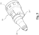
- a nozzle assembly otherwise identical to the one described above adopts a different rotor, illustrated in figures 9-10 .
- the counterweight 30" has a spherical shape embedded within the coupling seat 21 of the support 10.
Landscapes
- Nozzles (AREA)
- Cleaning By Liquid Or Steam (AREA)
Priority Applications (13)
| Application Number | Priority Date | Filing Date | Title |
|---|---|---|---|
| ES21175971T ES2965058T3 (es) | 2018-11-05 | 2018-11-05 | Conjunto de boquilla de chorro giratorio para dispositivos de limpieza a presión |
| EP21175971.7A EP3888796B1 (de) | 2018-11-05 | 2018-11-05 | Rotierende strahldüsenanordnung für druckreinigungsvorrichtungen |
| DK21175971.7T DK3888796T3 (en) | 2018-11-05 | 2018-11-05 | Rotary jet nozzle assembly for pressure cleaning devices |
| EP18425083.5A EP3646953B2 (de) | 2018-11-05 | 2018-11-05 | Rotierende strahldüsenanordnung für druckreinigungsvorrichtungen |
| DK18425083.5T DK3646953T4 (en) | 2018-11-05 | 2018-11-05 | Rotary jet nozzle assembly for pressure cleaning devices |
| ES18425083T ES2890531T3 (es) | 2018-11-05 | 2018-11-05 | Conjunto de boquilla de chorro giratorio para dispositivos de limpieza a presión |
| CN201980072910.1A CN113164990B (zh) | 2018-11-05 | 2019-11-04 | 用于压力清洁装置的旋转射流喷嘴组件 |
| AU2019374388A AU2019374388A1 (en) | 2018-11-05 | 2019-11-04 | Rotary jet nozzle assembly for pressure cleaning devices |
| JP2021523716A JP7490252B2 (ja) | 2018-11-05 | 2019-11-04 | 圧力洗浄装置用の回転ジェットノズルアセンブリ |
| PCT/EP2019/080128 WO2020094584A1 (en) | 2018-11-05 | 2019-11-04 | Rotary jet nozzle assembly for pressure cleaning devices |
| US17/291,124 US20210387210A1 (en) | 2018-11-05 | 2019-11-04 | Rotary jet nozzle assembly for pressure cleaning devices |
| CA3118390A CA3118390A1 (en) | 2018-11-05 | 2019-11-04 | Rotary jet nozzle assembly for pressure cleaning devices |
| AU2025220779A AU2025220779A1 (en) | 2018-11-05 | 2025-08-21 | Rotary jet nozzle assembly for pressure cleaning devices |
Applications Claiming Priority (1)
| Application Number | Priority Date | Filing Date | Title |
|---|---|---|---|
| EP18425083.5A EP3646953B2 (de) | 2018-11-05 | 2018-11-05 | Rotierende strahldüsenanordnung für druckreinigungsvorrichtungen |
Related Child Applications (2)
| Application Number | Title | Priority Date | Filing Date |
|---|---|---|---|
| EP21175971.7A Division-Into EP3888796B1 (de) | 2018-11-05 | 2018-11-05 | Rotierende strahldüsenanordnung für druckreinigungsvorrichtungen |
| EP21175971.7A Division EP3888796B1 (de) | 2018-11-05 | 2018-11-05 | Rotierende strahldüsenanordnung für druckreinigungsvorrichtungen |
Publications (3)
| Publication Number | Publication Date |
|---|---|
| EP3646953A1 true EP3646953A1 (de) | 2020-05-06 |
| EP3646953B1 EP3646953B1 (de) | 2021-07-14 |
| EP3646953B2 EP3646953B2 (de) | 2026-03-25 |
Family
ID=64959191
Family Applications (2)
| Application Number | Title | Priority Date | Filing Date |
|---|---|---|---|
| EP18425083.5A Active EP3646953B2 (de) | 2018-11-05 | 2018-11-05 | Rotierende strahldüsenanordnung für druckreinigungsvorrichtungen |
| EP21175971.7A Active EP3888796B1 (de) | 2018-11-05 | 2018-11-05 | Rotierende strahldüsenanordnung für druckreinigungsvorrichtungen |
Family Applications After (1)
| Application Number | Title | Priority Date | Filing Date |
|---|---|---|---|
| EP21175971.7A Active EP3888796B1 (de) | 2018-11-05 | 2018-11-05 | Rotierende strahldüsenanordnung für druckreinigungsvorrichtungen |
Country Status (9)
| Country | Link |
|---|---|
| US (1) | US20210387210A1 (de) |
| EP (2) | EP3646953B2 (de) |
| JP (1) | JP7490252B2 (de) |
| CN (1) | CN113164990B (de) |
| AU (2) | AU2019374388A1 (de) |
| CA (1) | CA3118390A1 (de) |
| DK (2) | DK3888796T3 (de) |
| ES (2) | ES2965058T3 (de) |
| WO (1) | WO2020094584A1 (de) |
Cited By (3)
| Publication number | Priority date | Publication date | Assignee | Title |
|---|---|---|---|---|
| EP3892382A1 (de) * | 2020-04-09 | 2021-10-13 | Suttner GmbH | Rotordüse |
| EP3892383A1 (de) * | 2020-04-09 | 2021-10-13 | Suttner GmbH | Rotordüse |
| WO2022128085A1 (de) | 2020-12-16 | 2022-06-23 | Alfred Kärcher SE & Co. KG | Rotordüse für ein hochdruckreinigungsgerät |
Citations (4)
| Publication number | Priority date | Publication date | Assignee | Title |
|---|---|---|---|---|
| EP1072317A2 (de) * | 1999-07-27 | 2001-01-31 | Wolfgang Suttner | Rotordüse für einen Hochdruckreiniger und Verfahren zur Herstellung einer Rotordüse |
| DE102005028886A1 (de) * | 2005-06-22 | 2007-01-04 | Jäger, Anton | Vorrichtung zum Ausstoßen eines Fluids |
| DE102005037858A1 (de) * | 2005-08-10 | 2007-02-15 | Jäger, Anton | Rotationsdüse |
| US20170144174A1 (en) * | 2015-11-25 | 2017-05-25 | Karl J. Fritze | Compact linear oscillating water jet |
Family Cites Families (61)
| Publication number | Priority date | Publication date | Assignee | Title |
|---|---|---|---|---|
| DE3623368C2 (de) | 1986-07-11 | 1993-12-02 | Kaercher Gmbh & Co Alfred | Rotordüse für ein Hochdruckreinigungsgerät |
| DE3836053C1 (de) | 1988-10-22 | 1990-01-11 | Alfred Kaercher Gmbh & Co, 7057 Winnenden, De | |
| DE3902478C1 (de) * | 1989-01-27 | 1990-07-19 | Josef 7918 Illertissen De Kraenzle | |
| DE4013446C1 (de) * | 1990-04-27 | 1991-05-08 | Alfred Kaercher Gmbh & Co, 7057 Winnenden, De | |
| US5163615A (en) * | 1991-07-01 | 1992-11-17 | Kurita Water Industries, Ltd. | Generator for cyclically moving jets |
| DE4129026C1 (de) * | 1991-08-31 | 1993-03-04 | Alfred Kaercher Gmbh & Co, 7057 Winnenden, De | |
| DE4220561A1 (de) | 1991-09-27 | 1993-04-01 | Suttner Gmbh & Co Kg | Punktstrahl-rotationsduese fuer hochdruckreinigungsgeraete |
| IT1253802B (it) * | 1991-11-15 | 1995-08-23 | Ugello per la generazione di un getto rotante. | |
| DE4239542A1 (de) * | 1992-03-28 | 1993-09-30 | Anton Jaeger | Rotordüse für ein Hochdruckreinigungsgerät |
| DE4433646C2 (de) * | 1993-09-29 | 1996-10-10 | Anton Jaeger | Rotordüse, insbesondere für ein Hochdruckreinigungsgerät |
| DE4340184A1 (de) * | 1993-11-25 | 1995-06-01 | Anton Jaeger | Spritzdüse, insbesondere für Hochdruckreinigungsgeräte |
| DE19511820A1 (de) * | 1995-03-30 | 1996-10-02 | Anton Jaeger | Rotordüse, insbesondere für ein Hochdruckreinigungsgerät |
| DE19632323A1 (de) * | 1996-08-10 | 1998-02-12 | Kaercher Gmbh & Co Alfred | Rotordüse für ein Hochdruckreinigungsgerät |
| NL1006604C1 (nl) * | 1996-10-24 | 1998-04-27 | H T Research B V | Inrichting en werkwijze voor het reinigen van oppervlakken. |
| DE19703043A1 (de) * | 1997-01-28 | 1998-07-30 | Anton Jaeger Reinigungstechnik | Rotordüsenkopf |
| EP0865827B1 (de) * | 1997-03-20 | 2003-01-02 | Suttner Gmbh & Co. Kg | Rotordüse für ein Hochdruckreinigungsgerät |
| IT1298008B1 (it) * | 1997-12-19 | 1999-12-20 | Annovi E Reverberi S R L | Lancia di lavaggio ad ugello rotante |
| DE19821919B4 (de) * | 1998-05-15 | 2013-05-16 | Anton Jäger | Rotordüse |
| DE19832568C2 (de) * | 1998-07-20 | 2003-04-30 | Anton Jaeger | Rotordüse |
| DE10006864B4 (de) * | 2000-02-16 | 2006-02-09 | Spraying Systems Deutschland Gmbh | Reinigungsdüse |
| DE20115089U1 (de) | 2001-07-31 | 2001-11-29 | Suttner Gmbh & Co Kg, 33689 Bielefeld | Rotordüse für ein Hochdruckreinigungsgerät |
| DE10154509A1 (de) * | 2001-11-07 | 2003-05-22 | Anton Jaeger | Rotordüse, insbesondere für Hochdruckreiniger |
| US6766967B2 (en) * | 2002-05-07 | 2004-07-27 | Gp Companies, Inc. | Magnet-driven rotary nozzle |
| JP2004154732A (ja) * | 2002-11-08 | 2004-06-03 | Toto Ltd | 吐水装置 |
| ITRE20030076A1 (it) * | 2003-08-07 | 2005-02-08 | Arrow Line Srl | Testina a piu' funzioni per pistole di lavaggio ad |
| US7273188B2 (en) * | 2003-08-15 | 2007-09-25 | Darrell R Saha | Internal self-rotating fluid jetting nozzle |
| ITMI20040094A1 (it) * | 2004-01-23 | 2004-04-23 | Interpump Cleaning S P A Div F | Lancia con ugello erogatore a movimentazione multipla per apparecchiature di lavaggio ad alta pressione |
| DE102004047586B4 (de) * | 2004-09-23 | 2006-10-05 | Alfred Kärcher Gmbh & Co. Kg | Reinigungskopf |
| US7111796B2 (en) * | 2004-09-29 | 2006-09-26 | Olson Donald O | Sprinkler apparatus and related methods |
| DE502005000330D1 (de) * | 2005-05-03 | 2007-03-08 | Einhell Hans Ag | Rotordüse für ein Reinigungsgerät |
| US7118051B1 (en) | 2005-08-11 | 2006-10-10 | Anton Jager | Rotor nozzle |
| DE102006019078B4 (de) * | 2006-04-25 | 2021-11-11 | Anton Jäger | Rotordüse |
| EP2038067B1 (de) | 2006-06-30 | 2017-11-29 | Nilfisk A/S | Drehdüse |
| EP1920847B1 (de) * | 2006-11-09 | 2017-04-05 | Nilfisk A/S | Rotordüse für ein Hochdruckreinigungsgerät |
| DE202007005846U1 (de) * | 2007-04-20 | 2007-06-28 | Schafstein, Bernd | Flüssigkeitsrichter für eine Rotordüse |
| DE202007006088U1 (de) * | 2007-04-26 | 2007-06-28 | Hans Einhell Ag | Rotordüse für ein Reinigungsgerät |
| US20090113642A1 (en) * | 2007-11-06 | 2009-05-07 | Arrow Line S.R.L. | Device for washing liquid turbulation for rotary jet heads, especially water-cleaning machines |
| WO2009094645A2 (en) * | 2008-01-24 | 2009-07-30 | Hydra-Flex Inc. | Configurable rotary spray nozzle |
| ITMO20080043A1 (it) * | 2008-02-19 | 2009-08-20 | P A S R L | Valvola di by-pass e di regolazione pressione perfezionata. |
| DE102008010690A1 (de) * | 2008-02-22 | 2009-08-27 | Jäger, Anton | Rotordüse |
| DE102009020409A1 (de) * | 2009-05-08 | 2010-11-18 | Jäger, Anton | Rotordüse |
| US9016293B2 (en) * | 2009-08-21 | 2015-04-28 | Gas Turbine Efficiency Sweden Ab | Staged compressor water wash system |
| KR101112683B1 (ko) * | 2011-06-21 | 2012-02-15 | 주식회사 유천엔바이로 | 자동 세척 노즐 |
| JP6147623B2 (ja) * | 2013-09-17 | 2017-06-14 | 株式会社スギノマシン | タレット装置 |
| DE102014100530A1 (de) * | 2014-01-17 | 2015-07-23 | Alfred Kärcher Gmbh & Co. Kg | Schaltventilvorrichtung und Hochdruckflüssigkeitsanlage umfassend eine Schaltventilvorrichtung |
| US9587776B2 (en) * | 2014-02-03 | 2017-03-07 | Gene G. Yie | Method and apparatus for generating self rotating fluid jet |
| US9731303B2 (en) * | 2014-03-31 | 2017-08-15 | Hydra-Flex, Inc. | Oscillating nozzles |
| DE102014006647A1 (de) * | 2014-05-07 | 2015-11-12 | Dürr Systems GmbH | Reinigungsgerät für einen Zerstäuber und zugehöriges Betriebsverfahren |
| ITUB20150482A1 (it) * | 2015-02-10 | 2016-08-10 | Tecomec Srl | Ugello a getto rotante |
| JP2018505781A (ja) * | 2015-02-23 | 2018-03-01 | ストーンエイジ, インコーポレイテッドStoneage, Inc. | スプレー角度が内部調節可能な回転ノズル |
| PL3265235T3 (pl) * | 2015-03-02 | 2019-06-28 | Alfred Kärcher SE & Co. KG | Dysza wirnikowa dla wysokociśnieniowego urządzenia czyszczącego |
| EP3463700B1 (de) * | 2016-05-23 | 2021-04-07 | Robowash Pty Ltd | Vorrichtung und verfahren zur reinigung von maschinen |
| IT201600072149A1 (it) * | 2016-07-11 | 2018-01-11 | Leuco Spa | Pompa per erogare un liquido. |
| EP3552721A4 (de) * | 2016-12-06 | 2020-08-12 | Positec Power Tools (Suzhou) Co., Ltd | Hochdruckreinigungsmaschine und hochdruckreinigungsmaschinenanordnung |
| DE102017110765B4 (de) * | 2017-05-17 | 2022-03-03 | Anton Jäger | Rotordüse und Verfahren zum Erhöhen der Standzeit eines Lagers in einer Rotordüse |
| CA2972055C (en) * | 2017-06-29 | 2021-01-26 | Conseiller Forestier Roy Inc. | Airborne material spreading assembly and method for spreading material |
| US11369979B2 (en) * | 2017-08-10 | 2022-06-28 | Church & Dwight Co., Inc. | High impact spray nozzle |
| JP6792534B2 (ja) * | 2017-10-11 | 2020-11-25 | 株式会社ニフコ | 流体吐出機構、及び車両用カメラ又はセンサーに対する流体の吹き付け装置 |
| US11420223B2 (en) * | 2018-06-15 | 2022-08-23 | Veeco Instruments Inc. | High pressure spray head |
| DE102018125883A1 (de) * | 2018-10-18 | 2020-04-23 | Krones Ag | Rotationsreinigungsdüse und Reinigungssystem zum Reinigen von Oberflächen in einer Getränkeabfüllanlage |
| JP2020094622A (ja) * | 2018-12-12 | 2020-06-18 | 株式会社小糸製作所 | 車両用クリーナシステム |
-
2018
- 2018-11-05 EP EP18425083.5A patent/EP3646953B2/de active Active
- 2018-11-05 ES ES21175971T patent/ES2965058T3/es active Active
- 2018-11-05 DK DK21175971.7T patent/DK3888796T3/da active
- 2018-11-05 DK DK18425083.5T patent/DK3646953T4/da active
- 2018-11-05 ES ES18425083T patent/ES2890531T3/es active Active
- 2018-11-05 EP EP21175971.7A patent/EP3888796B1/de active Active
-
2019
- 2019-11-04 JP JP2021523716A patent/JP7490252B2/ja active Active
- 2019-11-04 WO PCT/EP2019/080128 patent/WO2020094584A1/en not_active Ceased
- 2019-11-04 CA CA3118390A patent/CA3118390A1/en active Pending
- 2019-11-04 AU AU2019374388A patent/AU2019374388A1/en not_active Abandoned
- 2019-11-04 CN CN201980072910.1A patent/CN113164990B/zh active Active
- 2019-11-04 US US17/291,124 patent/US20210387210A1/en active Pending
-
2025
- 2025-08-21 AU AU2025220779A patent/AU2025220779A1/en active Pending
Patent Citations (4)
| Publication number | Priority date | Publication date | Assignee | Title |
|---|---|---|---|---|
| EP1072317A2 (de) * | 1999-07-27 | 2001-01-31 | Wolfgang Suttner | Rotordüse für einen Hochdruckreiniger und Verfahren zur Herstellung einer Rotordüse |
| DE102005028886A1 (de) * | 2005-06-22 | 2007-01-04 | Jäger, Anton | Vorrichtung zum Ausstoßen eines Fluids |
| DE102005037858A1 (de) * | 2005-08-10 | 2007-02-15 | Jäger, Anton | Rotationsdüse |
| US20170144174A1 (en) * | 2015-11-25 | 2017-05-25 | Karl J. Fritze | Compact linear oscillating water jet |
Cited By (3)
| Publication number | Priority date | Publication date | Assignee | Title |
|---|---|---|---|---|
| EP3892382A1 (de) * | 2020-04-09 | 2021-10-13 | Suttner GmbH | Rotordüse |
| EP3892383A1 (de) * | 2020-04-09 | 2021-10-13 | Suttner GmbH | Rotordüse |
| WO2022128085A1 (de) | 2020-12-16 | 2022-06-23 | Alfred Kärcher SE & Co. KG | Rotordüse für ein hochdruckreinigungsgerät |
Also Published As
| Publication number | Publication date |
|---|---|
| AU2019374388A1 (en) | 2021-05-20 |
| EP3646953B2 (de) | 2026-03-25 |
| WO2020094584A1 (en) | 2020-05-14 |
| AU2025220779A1 (en) | 2025-09-11 |
| CN113164990B (zh) | 2023-09-29 |
| DK3888796T3 (en) | 2023-11-13 |
| JP2022519797A (ja) | 2022-03-25 |
| ES2965058T3 (es) | 2024-04-10 |
| CN113164990A (zh) | 2021-07-23 |
| ES2890531T3 (es) | 2022-01-20 |
| US20210387210A1 (en) | 2021-12-16 |
| CA3118390A1 (en) | 2020-05-14 |
| EP3888796B1 (de) | 2023-08-30 |
| JP7490252B2 (ja) | 2024-05-27 |
| DK3646953T4 (en) | 2026-04-07 |
| EP3888796A1 (de) | 2021-10-06 |
| EP3646953B1 (de) | 2021-07-14 |
| DK3646953T3 (en) | 2021-10-11 |
Similar Documents
| Publication | Publication Date | Title |
|---|---|---|
| AU2025220779A1 (en) | Rotary jet nozzle assembly for pressure cleaning devices | |
| DK168196B1 (da) | Rotordyse, især til en højtryksrenser | |
| US5395053A (en) | Rotor nozzle for a high-pressure cleaning device | |
| EP3925566B1 (de) | Fluidbetriebenes medizinisches oder zahnmedizinisches handgerät | |
| US4453919A (en) | Dental scaler | |
| US10040078B2 (en) | Compact linear oscillating water jet | |
| US2967024A (en) | Dish washing machine | |
| US3124878A (en) | Sonic dental tool | |
| US4484892A (en) | Hand-held pneumatic implement for removing dental scale | |
| CN101444767B (zh) | 折射旋转仰角可变式喷头 | |
| EP1907169B1 (de) | Rotationswerkzeug | |
| CN115788278A (zh) | 螺杆式脉冲减阻钻具 | |
| JP3619598B2 (ja) | 被加工物の内壁をサンドブラストする装置および方法 | |
| CN213194258U (zh) | 一种含无拼缝耐磨环的耐磨型雾化盘 | |
| CN210208682U (zh) | 中心出水主轴水气交替管路结构 | |
| CN101389448A (zh) | 流动介质驱动的手持式工具机 | |
| CN116398486B (zh) | 一种具有磁性检测功能的磁力泵 | |
| JP2022553896A (ja) | 複数のタービンを有する駆動式工具ホルダ | |
| JPS58160058A (ja) | 回転研削砥石の自動バランサ−装置 | |
| SU1063585A1 (ru) | Устройство дл абразивной обработки деталей | |
| TWM504576U (zh) | 洗牙機 | |
| CN210389719U (zh) | 防溅射装置及开方系统 | |
| RU198097U1 (ru) | Гидромониторная роторная насадка для очистки внутренней полости труб от твердых отложений | |
| RU1801709C (ru) | Устройство дл импульсной резки проката | |
| CN118478277A (zh) | 一种加工中心用的打磨装置 |
Legal Events
| Date | Code | Title | Description |
|---|---|---|---|
| PUAI | Public reference made under article 153(3) epc to a published international application that has entered the european phase |
Free format text: ORIGINAL CODE: 0009012 |
|
| STAA | Information on the status of an ep patent application or granted ep patent |
Free format text: STATUS: THE APPLICATION HAS BEEN PUBLISHED |
|
| AK | Designated contracting states |
Kind code of ref document: A1 Designated state(s): AL AT BE BG CH CY CZ DE DK EE ES FI FR GB GR HR HU IE IS IT LI LT LU LV MC MK MT NL NO PL PT RO RS SE SI SK SM TR |
|
| AX | Request for extension of the european patent |
Extension state: BA ME |
|
| STAA | Information on the status of an ep patent application or granted ep patent |
Free format text: STATUS: REQUEST FOR EXAMINATION WAS MADE |
|
| 17P | Request for examination filed |
Effective date: 20201105 |
|
| RBV | Designated contracting states (corrected) |
Designated state(s): AL AT BE BG CH CY CZ DE DK EE ES FI FR GB GR HR HU IE IS IT LI LT LU LV MC MK MT NL NO PL PT RO RS SE SI SK SM TR |
|
| TPAC | Observations filed by third parties |
Free format text: ORIGINAL CODE: EPIDOSNTIPA |
|
| GRAP | Despatch of communication of intention to grant a patent |
Free format text: ORIGINAL CODE: EPIDOSNIGR1 |
|
| STAA | Information on the status of an ep patent application or granted ep patent |
Free format text: STATUS: GRANT OF PATENT IS INTENDED |
|
| INTG | Intention to grant announced |
Effective date: 20210129 |
|
| GRAS | Grant fee paid |
Free format text: ORIGINAL CODE: EPIDOSNIGR3 |
|
| GRAA | (expected) grant |
Free format text: ORIGINAL CODE: 0009210 |
|
| STAA | Information on the status of an ep patent application or granted ep patent |
Free format text: STATUS: THE PATENT HAS BEEN GRANTED |
|
| AK | Designated contracting states |
Kind code of ref document: B1 Designated state(s): AL AT BE BG CH CY CZ DE DK EE ES FI FR GB GR HR HU IE IS IT LI LT LU LV MC MK MT NL NO PL PT RO RS SE SI SK SM TR |
|
| RAP3 | Party data changed (applicant data changed or rights of an application transferred) |
Owner name: P.A. S.P.A. |
|
| REG | Reference to a national code |
Ref country code: GB Ref legal event code: FG4D |
|
| REG | Reference to a national code |
Ref country code: IE Ref legal event code: FG4D |
|
| REG | Reference to a national code |
Ref country code: DE Ref legal event code: R096 Ref document number: 602018020053 Country of ref document: DE |
|
| REG | Reference to a national code |
Ref country code: AT Ref legal event code: REF Ref document number: 1410238 Country of ref document: AT Kind code of ref document: T Effective date: 20210815 |
|
| REG | Reference to a national code |
Ref country code: DK Ref legal event code: T3 Effective date: 20211004 |
|
| REG | Reference to a national code |
Ref country code: NL Ref legal event code: FP |
|
| REG | Reference to a national code |
Ref country code: LT Ref legal event code: MG9D |
|
| REG | Reference to a national code |
Ref country code: AT Ref legal event code: MK05 Ref document number: 1410238 Country of ref document: AT Kind code of ref document: T Effective date: 20210714 |
|
| REG | Reference to a national code |
Ref country code: ES Ref legal event code: FG2A Ref document number: 2890531 Country of ref document: ES Kind code of ref document: T3 Effective date: 20220120 |
|
| PG25 | Lapsed in a contracting state [announced via postgrant information from national office to epo] |
Ref country code: AT Free format text: LAPSE BECAUSE OF FAILURE TO SUBMIT A TRANSLATION OF THE DESCRIPTION OR TO PAY THE FEE WITHIN THE PRESCRIBED TIME-LIMIT Effective date: 20210714 Ref country code: BG Free format text: LAPSE BECAUSE OF FAILURE TO SUBMIT A TRANSLATION OF THE DESCRIPTION OR TO PAY THE FEE WITHIN THE PRESCRIBED TIME-LIMIT Effective date: 20211014 Ref country code: LT Free format text: LAPSE BECAUSE OF FAILURE TO SUBMIT A TRANSLATION OF THE DESCRIPTION OR TO PAY THE FEE WITHIN THE PRESCRIBED TIME-LIMIT Effective date: 20210714 Ref country code: NO Free format text: LAPSE BECAUSE OF FAILURE TO SUBMIT A TRANSLATION OF THE DESCRIPTION OR TO PAY THE FEE WITHIN THE PRESCRIBED TIME-LIMIT Effective date: 20211014 Ref country code: PT Free format text: LAPSE BECAUSE OF FAILURE TO SUBMIT A TRANSLATION OF THE DESCRIPTION OR TO PAY THE FEE WITHIN THE PRESCRIBED TIME-LIMIT Effective date: 20211115 Ref country code: SE Free format text: LAPSE BECAUSE OF FAILURE TO SUBMIT A TRANSLATION OF THE DESCRIPTION OR TO PAY THE FEE WITHIN THE PRESCRIBED TIME-LIMIT Effective date: 20210714 Ref country code: RS Free format text: LAPSE BECAUSE OF FAILURE TO SUBMIT A TRANSLATION OF THE DESCRIPTION OR TO PAY THE FEE WITHIN THE PRESCRIBED TIME-LIMIT Effective date: 20210714 Ref country code: FI Free format text: LAPSE BECAUSE OF FAILURE TO SUBMIT A TRANSLATION OF THE DESCRIPTION OR TO PAY THE FEE WITHIN THE PRESCRIBED TIME-LIMIT Effective date: 20210714 Ref country code: HR Free format text: LAPSE BECAUSE OF FAILURE TO SUBMIT A TRANSLATION OF THE DESCRIPTION OR TO PAY THE FEE WITHIN THE PRESCRIBED TIME-LIMIT Effective date: 20210714 |
|
| PG25 | Lapsed in a contracting state [announced via postgrant information from national office to epo] |
Ref country code: PL Free format text: LAPSE BECAUSE OF FAILURE TO SUBMIT A TRANSLATION OF THE DESCRIPTION OR TO PAY THE FEE WITHIN THE PRESCRIBED TIME-LIMIT Effective date: 20210714 Ref country code: LV Free format text: LAPSE BECAUSE OF FAILURE TO SUBMIT A TRANSLATION OF THE DESCRIPTION OR TO PAY THE FEE WITHIN THE PRESCRIBED TIME-LIMIT Effective date: 20210714 Ref country code: GR Free format text: LAPSE BECAUSE OF FAILURE TO SUBMIT A TRANSLATION OF THE DESCRIPTION OR TO PAY THE FEE WITHIN THE PRESCRIBED TIME-LIMIT Effective date: 20211015 |
|
| REG | Reference to a national code |
Ref country code: DE Ref legal event code: R026 Ref document number: 602018020053 Country of ref document: DE |
|
| PLBI | Opposition filed |
Free format text: ORIGINAL CODE: 0009260 |
|
| PLAB | Opposition data, opponent's data or that of the opponent's representative modified |
Free format text: ORIGINAL CODE: 0009299OPPO |
|
| PLAX | Notice of opposition and request to file observation + time limit sent |
Free format text: ORIGINAL CODE: EPIDOSNOBS2 |
|
| 26 | Opposition filed |
Opponent name: PETERSEN, FRANK Effective date: 20220408 |
|
| PG25 | Lapsed in a contracting state [announced via postgrant information from national office to epo] |
Ref country code: SM Free format text: LAPSE BECAUSE OF FAILURE TO SUBMIT A TRANSLATION OF THE DESCRIPTION OR TO PAY THE FEE WITHIN THE PRESCRIBED TIME-LIMIT Effective date: 20210714 Ref country code: SK Free format text: LAPSE BECAUSE OF FAILURE TO SUBMIT A TRANSLATION OF THE DESCRIPTION OR TO PAY THE FEE WITHIN THE PRESCRIBED TIME-LIMIT Effective date: 20210714 Ref country code: RO Free format text: LAPSE BECAUSE OF FAILURE TO SUBMIT A TRANSLATION OF THE DESCRIPTION OR TO PAY THE FEE WITHIN THE PRESCRIBED TIME-LIMIT Effective date: 20210714 Ref country code: EE Free format text: LAPSE BECAUSE OF FAILURE TO SUBMIT A TRANSLATION OF THE DESCRIPTION OR TO PAY THE FEE WITHIN THE PRESCRIBED TIME-LIMIT Effective date: 20210714 Ref country code: CZ Free format text: LAPSE BECAUSE OF FAILURE TO SUBMIT A TRANSLATION OF THE DESCRIPTION OR TO PAY THE FEE WITHIN THE PRESCRIBED TIME-LIMIT Effective date: 20210714 Ref country code: AL Free format text: LAPSE BECAUSE OF FAILURE TO SUBMIT A TRANSLATION OF THE DESCRIPTION OR TO PAY THE FEE WITHIN THE PRESCRIBED TIME-LIMIT Effective date: 20210714 |
|
| R26 | Opposition filed (corrected) |
Opponent name: PETERSEN, FRANK Effective date: 20220408 |
|
| PG25 | Lapsed in a contracting state [announced via postgrant information from national office to epo] |
Ref country code: MC Free format text: LAPSE BECAUSE OF FAILURE TO SUBMIT A TRANSLATION OF THE DESCRIPTION OR TO PAY THE FEE WITHIN THE PRESCRIBED TIME-LIMIT Effective date: 20210714 |
|
| REG | Reference to a national code |
Ref country code: CH Ref legal event code: PL |
|
| PG25 | Lapsed in a contracting state [announced via postgrant information from national office to epo] |
Ref country code: LU Free format text: LAPSE BECAUSE OF NON-PAYMENT OF DUE FEES Effective date: 20211105 |
|
| PG25 | Lapsed in a contracting state [announced via postgrant information from national office to epo] |
Ref country code: LI Free format text: LAPSE BECAUSE OF NON-PAYMENT OF DUE FEES Effective date: 20211130 Ref country code: CH Free format text: LAPSE BECAUSE OF NON-PAYMENT OF DUE FEES Effective date: 20211130 |
|
| PLBB | Reply of patent proprietor to notice(s) of opposition received |
Free format text: ORIGINAL CODE: EPIDOSNOBS3 |
|
| PG25 | Lapsed in a contracting state [announced via postgrant information from national office to epo] |
Ref country code: IE Free format text: LAPSE BECAUSE OF NON-PAYMENT OF DUE FEES Effective date: 20211105 |
|
| P01 | Opt-out of the competence of the unified patent court (upc) registered |
Effective date: 20230510 |
|
| PG25 | Lapsed in a contracting state [announced via postgrant information from national office to epo] |
Ref country code: CY Free format text: LAPSE BECAUSE OF FAILURE TO SUBMIT A TRANSLATION OF THE DESCRIPTION OR TO PAY THE FEE WITHIN THE PRESCRIBED TIME-LIMIT Effective date: 20210714 |
|
| PG25 | Lapsed in a contracting state [announced via postgrant information from national office to epo] |
Ref country code: HU Free format text: LAPSE BECAUSE OF FAILURE TO SUBMIT A TRANSLATION OF THE DESCRIPTION OR TO PAY THE FEE WITHIN THE PRESCRIBED TIME-LIMIT; INVALID AB INITIO Effective date: 20181105 |
|
| PG25 | Lapsed in a contracting state [announced via postgrant information from national office to epo] |
Ref country code: MK Free format text: LAPSE BECAUSE OF FAILURE TO SUBMIT A TRANSLATION OF THE DESCRIPTION OR TO PAY THE FEE WITHIN THE PRESCRIBED TIME-LIMIT Effective date: 20210714 |
|
| PG25 | Lapsed in a contracting state [announced via postgrant information from national office to epo] |
Ref country code: TR Free format text: LAPSE BECAUSE OF FAILURE TO SUBMIT A TRANSLATION OF THE DESCRIPTION OR TO PAY THE FEE WITHIN THE PRESCRIBED TIME-LIMIT Effective date: 20210714 |
|
| APAH | Appeal reference modified |
Free format text: ORIGINAL CODE: EPIDOSCREFNO |
|
| APBP | Date of receipt of notice of appeal recorded |
Free format text: ORIGINAL CODE: EPIDOSNNOA2O |
|
| PLBP | Opposition withdrawn |
Free format text: ORIGINAL CODE: 0009264 |
|
| APBQ | Date of receipt of statement of grounds of appeal recorded |
Free format text: ORIGINAL CODE: EPIDOSNNOA3O |
|
| PG25 | Lapsed in a contracting state [announced via postgrant information from national office to epo] |
Ref country code: MT Free format text: LAPSE BECAUSE OF FAILURE TO SUBMIT A TRANSLATION OF THE DESCRIPTION OR TO PAY THE FEE WITHIN THE PRESCRIBED TIME-LIMIT Effective date: 20210714 |
|
| PGFP | Annual fee paid to national office [announced via postgrant information from national office to epo] |
Ref country code: NL Payment date: 20251022 Year of fee payment: 8 |
|
| APBU | Appeal procedure closed |
Free format text: ORIGINAL CODE: EPIDOSNNOA9O |
|
| PGFP | Annual fee paid to national office [announced via postgrant information from national office to epo] |
Ref country code: DE Payment date: 20251022 Year of fee payment: 8 |
|
| PGFP | Annual fee paid to national office [announced via postgrant information from national office to epo] |
Ref country code: GB Payment date: 20251023 Year of fee payment: 8 |
|
| PGFP | Annual fee paid to national office [announced via postgrant information from national office to epo] |
Ref country code: DK Payment date: 20251022 Year of fee payment: 8 Ref country code: IT Payment date: 20251118 Year of fee payment: 8 |
|
| PGFP | Annual fee paid to national office [announced via postgrant information from national office to epo] |
Ref country code: FR Payment date: 20251022 Year of fee payment: 8 |
|
| PGFP | Annual fee paid to national office [announced via postgrant information from national office to epo] |
Ref country code: BE Payment date: 20251022 Year of fee payment: 8 |
|
| PGFP | Annual fee paid to national office [announced via postgrant information from national office to epo] |
Ref country code: ES Payment date: 20251201 Year of fee payment: 8 |
|
| PUAH | Patent maintained in amended form |
Free format text: ORIGINAL CODE: 0009272 |
|
| STAA | Information on the status of an ep patent application or granted ep patent |
Free format text: STATUS: PATENT MAINTAINED AS AMENDED |
|
| REG | Reference to a national code |
Ref country code: CH Ref legal event code: M12 Free format text: ST27 STATUS EVENT CODE: U-0-0-M10-M12 (AS PROVIDED BY THE NATIONAL OFFICE) Effective date: 20260225 |
|
| 27A | Patent maintained in amended form |
Effective date: 20260325 |
|
| AK | Designated contracting states |
Kind code of ref document: B2 Designated state(s): AL AT BE BG CH CY CZ DE DK EE ES FI FR GB GR HR HU IE IS IT LI LT LU LV MC MK MT NL NO PL PT RO RS SE SI SK SM TR |
|
| REG | Reference to a national code |
Ref country code: DE Ref legal event code: R102 Ref document number: 602018020053 Country of ref document: DE |
|
| REG | Reference to a national code |
Ref country code: DK Ref legal event code: T4 Effective date: 20260331 |
|
| REG | Reference to a national code |
Ref country code: NL Ref legal event code: FP |