EP3647521B1 - Fenêtre de toit comprenant un actionneur de chaine pré-contrainte - Google Patents
Fenêtre de toit comprenant un actionneur de chaine pré-contrainte Download PDFInfo
- Publication number
- EP3647521B1 EP3647521B1 EP19203563.2A EP19203563A EP3647521B1 EP 3647521 B1 EP3647521 B1 EP 3647521B1 EP 19203563 A EP19203563 A EP 19203563A EP 3647521 B1 EP3647521 B1 EP 3647521B1
- Authority
- EP
- European Patent Office
- Prior art keywords
- sash
- push
- opening
- roof window
- bracket
- Prior art date
- Legal status (The legal status is an assumption and is not a legal conclusion. Google has not performed a legal analysis and makes no representation as to the accuracy of the status listed.)
- Active
Links
Images


Classifications
-
- E—FIXED CONSTRUCTIONS
- E05—LOCKS; KEYS; WINDOW OR DOOR FITTINGS; SAFES
- E05F—DEVICES FOR MOVING WINGS INTO OPEN OR CLOSED POSITION; CHECKS FOR WINGS; WING FITTINGS NOT OTHERWISE PROVIDED FOR, CONCERNED WITH THE FUNCTIONING OF THE WING
- E05F15/00—Power-operated mechanisms for wings
- E05F15/60—Power-operated mechanisms for wings using electrical actuators
- E05F15/603—Power-operated mechanisms for wings using electrical actuators using rotary electromotors
- E05F15/611—Power-operated mechanisms for wings using electrical actuators using rotary electromotors for swinging wings
- E05F15/616—Power-operated mechanisms for wings using electrical actuators using rotary electromotors for swinging wings operated by push-pull mechanisms
- E05F15/619—Power-operated mechanisms for wings using electrical actuators using rotary electromotors for swinging wings operated by push-pull mechanisms using flexible or rigid rack-and-pinion arrangements
-
- E—FIXED CONSTRUCTIONS
- E05—LOCKS; KEYS; WINDOW OR DOOR FITTINGS; SAFES
- E05F—DEVICES FOR MOVING WINGS INTO OPEN OR CLOSED POSITION; CHECKS FOR WINGS; WING FITTINGS NOT OTHERWISE PROVIDED FOR, CONCERNED WITH THE FUNCTIONING OF THE WING
- E05F11/00—Man-operated mechanisms for operating wings, including those which also operate the fastening
- E05F11/02—Man-operated mechanisms for operating wings, including those which also operate the fastening for wings in general, e.g. fanlights
- E05F11/04—Man-operated mechanisms for operating wings, including those which also operate the fastening for wings in general, e.g. fanlights with cords, chains or cables
- E05F11/06—Man-operated mechanisms for operating wings, including those which also operate the fastening for wings in general, e.g. fanlights with cords, chains or cables in guide-channels
-
- E—FIXED CONSTRUCTIONS
- E05—LOCKS; KEYS; WINDOW OR DOOR FITTINGS; SAFES
- E05D—HINGES OR SUSPENSION DEVICES FOR DOORS, WINDOWS OR WINGS
- E05D15/00—Suspension arrangements for wings
- E05D15/40—Suspension arrangements for wings supported on arms movable in vertical planes
-
- E—FIXED CONSTRUCTIONS
- E05—LOCKS; KEYS; WINDOW OR DOOR FITTINGS; SAFES
- E05D—HINGES OR SUSPENSION DEVICES FOR DOORS, WINDOWS OR WINGS
- E05D7/00—Hinges or pivots of special construction
- E05D7/08—Hinges or pivots of special construction for use in suspensions comprising two spigots placed at opposite edges of the wing, especially at the top and the bottom, e.g. trunnions
- E05D7/081—Hinges or pivots of special construction for use in suspensions comprising two spigots placed at opposite edges of the wing, especially at the top and the bottom, e.g. trunnions the pivot axis of the wing being situated near one edge of the wing, especially at the top and bottom, e.g. trunnions
-
- E—FIXED CONSTRUCTIONS
- E05—LOCKS; KEYS; WINDOW OR DOOR FITTINGS; SAFES
- E05D—HINGES OR SUSPENSION DEVICES FOR DOORS, WINDOWS OR WINGS
- E05D7/00—Hinges or pivots of special construction
- E05D7/08—Hinges or pivots of special construction for use in suspensions comprising two spigots placed at opposite edges of the wing, especially at the top and the bottom, e.g. trunnions
- E05D7/082—Hinges or pivots of special construction for use in suspensions comprising two spigots placed at opposite edges of the wing, especially at the top and the bottom, e.g. trunnions the pivot axis of the wing being situated at a considerable distance from the edges of the wing, e.g. for balanced wings
-
- E—FIXED CONSTRUCTIONS
- E05—LOCKS; KEYS; WINDOW OR DOOR FITTINGS; SAFES
- E05Y—INDEXING SCHEME ASSOCIATED WITH SUBCLASSES E05D AND E05F, RELATING TO CONSTRUCTION ELEMENTS, ELECTRIC CONTROL, POWER SUPPLY, POWER SIGNAL OR TRANSMISSION, USER INTERFACES, MOUNTING OR COUPLING, DETAILS, ACCESSORIES, AUXILIARY OPERATIONS NOT OTHERWISE PROVIDED FOR, APPLICATION THEREOF
- E05Y2201/00—Constructional elements; Accessories therefor
- E05Y2201/60—Suspension or transmission members; Accessories therefor
- E05Y2201/622—Suspension or transmission members elements
- E05Y2201/644—Flexible elongated pulling elements
- E05Y2201/656—Chains
-
- E—FIXED CONSTRUCTIONS
- E05—LOCKS; KEYS; WINDOW OR DOOR FITTINGS; SAFES
- E05Y—INDEXING SCHEME ASSOCIATED WITH SUBCLASSES E05D AND E05F, RELATING TO CONSTRUCTION ELEMENTS, ELECTRIC CONTROL, POWER SUPPLY, POWER SIGNAL OR TRANSMISSION, USER INTERFACES, MOUNTING OR COUPLING, DETAILS, ACCESSORIES, AUXILIARY OPERATIONS NOT OTHERWISE PROVIDED FOR, APPLICATION THEREOF
- E05Y2900/00—Application of doors, windows, wings or fittings thereof
- E05Y2900/10—Application of doors, windows, wings or fittings thereof for buildings or parts thereof
- E05Y2900/13—Type of wing
- E05Y2900/148—Windows
- E05Y2900/152—Roof windows
Definitions
- the disclosure relates to a roof window comprising a sash and a frame adapted for receiving the sash.
- the sash is optionally suspended from the frame by means of suspension arms, and the sash is configured to pivot around a pivot axis by means of an actuator so as to open the sash towards an outer side of the window.
- the push-pull chain of an electrically operated actuator can be collapsed and wound together when subjected to force extending in a first direction perpendicular to the longitudinal extension of the push-pull chain, while reaching and maintaining a straight configuration, or a slightly arched configuration, when being subjected to force extending in an opposite second direction.
- the push-pull chain is stable enough to carry the weight of the sash and subsequently be used to push the sash open or hold it in an open position.
- DE 10 2016 203452 shows such an actuator comprising a push-pull chain wherein the main part of the actuator is connected to the window frame, and the push-pull chain is visibly connected, to an inner or side surface of the sash, by means of a pivotable bracket and pin combination.
- DE 102 06 274 , EP 1 422 374 , DE 202 04 224 , and US 2 755 122 show other actuator solutions comprising push-pull chains.
- Such a push-pull chain actuator has to be individually adapted to fit the specific dimensions of the roof window, since the radius of the push-pull chain determines the size of the window sash.
- a roof window comprising a sash and a frame adapted for receiving the sash, the sash being configured to pivot around a pivot axis so as to open the sash towards an outer side of the window, the sash optionally being suspended from the frame by means of suspension arms, each optional suspension arm extending at least partially between the sash and the frame, the roof window further comprising at least one actuator adapted for pivoting the sash in relation to the frame against a load of the sash, the load mainly being caused by the weight of the sash, the actuator comprising a push-pull chain and a bracket, the bracket being rigidly connected to a first end of the push-pull chain, a second end of the push-pull chain being received in an actuator housing connected to the frame, the push-pull chain being adapted for bending freely in a first direction, past a configuration in which the push-pull chain forms a straight line, and only to a limited extent past the straight line configuration
- This solution provides a roof window having an actuator which is stabilized by a stabilizing force, generated by the load of the sash, and which assists in preventing accidental collapse of the push-pull chain of the actuator. Furthermore, an end of the actuator is easily connected to the sash of the roof window after the frame and subsequently the sash have been installed in the roof.
- the support point is laterally offset from the longitudinal extent of the push-pull chain in the first direction, allowing the push-pull chain to be stabilized when in an end position arched past its straight line configuration in the second opposite direction, which facilitates an actuator which can be used with sashes having different dimensions.
- the push-pull chain comprises a plurality of coupled links, wherein a last link at the first end of the push-pull chain forms the bracket, allowing the main part of the actuator, including a part of the bracket, to be at least partially collapsed or wound together within the housing.
- the bracket comprises a second opening adapted for receiving a pre-loading pin, the pre-loading pin extending through the second opening and connecting the bracket to one of the sash and the suspension arm, the load of the sash urging the push-pull chain to bend in the second opposite direction by the pre-loading pin applying the load of the sash onto the bracket.
- a center axis of the connection pin and a center axis of the pre-loading pin extend parallel with each other and substantially parallel with the pivot axis, allowing the bracket to be pivoted without inducing collapse of the push-pull chain.
- an open end of the second opening allows the pre-loading pin to at least partially exit the second opening, in a direction parallel with the longitudinal extent of the oblong first opening, if the load applied by the sash is reduced or reversed, preventing collapse of the push-pull chain should the sash be lifted upwards by e.g. wind.
- the roof window comprises a connecting plate, connected to at least one of the sash and the suspension arm, the connecting plate comprising connection openings aligned with the oblong first opening and the second opening, the connection pin and the pre-loading pin extending through the connection openings of the connecting plate, allowing a simple yet stable connection between actuator and sash.
- the bracket comprises first and second parallel bracket plates, an oblong first opening in the first bracket plate being aligned with an oblong first opening in the second bracket plate, and a second opening in the first bracket plate being aligned with a second opening in the second bracket plate, the bracket at least partially enclosing the connecting plate such that the first and second bracket plates extend on opposite sides of the connecting plate, facilitating an actuator which distributes force evenly upon the connection pin, the pre-loading pin and, hence, the sash.
- the actuator comprises locking means engaging the connection pin, the locking means being configured for preventing the connection pin from being removed from the oblong first opening.
- connection pin comprises a first pin end and a second pin end, the second pin end comprising an enlarged portion too large to pass through the oblong first opening, the first pin end engaging the locking means, the locking means and the first pin end being arranged in a recess within the sash side member or between the suspension arm and the sash, the second pin end being arranged between the frame and the sash or between the frame and the suspension arm.
- This solution facilitates use of the actuator in a window where the sash is suspended directly from the frame without the use of suspension arms and provides the locking means at a location which is unreachable from the exterior of the building when the sash is closed, as well as a simple and reliable way of interlocking components without, e.g., having to rely on moving parts.
- the locking means is releasable and comprises at least one of a threaded nut, a spring, a clip, a slider, and a pin, all being reliable and easy-to-operate mechanical solutions for interlocking components.
- the actuator further comprises a protective casing adapted for enclosing the locking means and the first pin end, further obstructing access to the locking means from the exterior as well as providing protection against external influence such as ingress of dirt, weather conditions, or unintentional mechanical forces such as bending forces.
- the casing comprises two casing halves, one casing half comprising an access opening allowing access to the locking means such that the locking means can be released from the connection pin, allowing the actuator to be released from the sash, facilitating a secure solution which still allows for simple connection of the actuator to the sash.
- the actuator further comprises chain support means, connected to at least one of the sash and the frame, adapted for providing a stabilizing force onto the push-pull chain perpendicularly to the longitudinal extension of the push-pull chain, the stabilizing force urging the push-pull chain to bend in the second opposite direction.
- the roof window is a top-hung roof window comprising one actuator, the actuator being arranged adjacent a frame bottom member.
- the roof window is a center-pivoted roof window or a top-hung roof window comprising two actuators, each actuator being arranged adjacent one frame side member.
- Figs. 1a and 1b show a roof window comprising a sash 1 and a frame 2 adapted for receiving the sash 1, the sash 1 being configured to pivot around a pivot axis A so as to open the sash towards an outer side of the window, i.e. towards the exterior of a building.
- the sash 1 comprises two sash side members 1a, 1b connected to a top sash member 1c and a bottom sash member 1d.
- the sash 1 may be suspended directly from the frame 2 or, optionally, suspended from the frame 2 by means of suspension arms 3.
- Each optional suspension arm 3 extends at least partially between a sash side member 1a, 1b and an adjacent frame side member 2a, 2b.
- At least one actuator 4 is provided to pivot the sash 1 between a closed position and several open positions in relation to the frame 2, open positions being shown in Figs. 1a and 1b .
- the actuator 4 may furthermore be adapted for securing the sash 1 in the closed position.
- the actuator 4 is adapted for pivoting the sash 1 in relation to the frame 2 against a load L of the sash 1, the load L mainly being caused by the weight of the sash 1.
- the load L may also be attributed to external conditions such as e.g. snow resting on the sash or wind.
- the actuator 4 comprises a push-pull chain 5 and a bracket 6, the bracket 6 being rigidly connected to a first end 5a of the push-pull chain.
- a second end 5b of the push-pull chain is received in an actuator housing 7 connected to the frame 2, as shown schematically in Fig. 1a .
- the push-pull chain 5 is withdrawn, completely or almost completely, into the actuator housing 7 by an electrical motor (not shown).
- the push-pull chain 5 is maintained in the withdrawn position by means of the motor or any other suitable locking means, such that the sash 1 is maintained in the closed position until the actuator 4 is activated in order move the sash 1 to an open position.
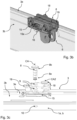
- the push-pull chain 5 comprises a plurality of coupled links 13, as shown in Fig. 2 .
- the last link 13a at the first end 5a of the push-pull chain forms the bracket 6.
- the bracket 6 is a separate component connected to the last link 13a of the push-pull chain 5.
- the push-pull chain 5 bends freely in a first direction D1, at least partially towards the pivot axis A, past a configuration in which the push-pull chain forms a straight line 5c, shown in Fig. 2 , such that at least the main part of the push-pull chain 6 can be collapsed and wound together.
- the push-pull chain 5 can bend only to a limited extent past the straight line 5c configuration in a second opposite direction D2, allowing the push-pull chain 5 to form an arc.
- the bracket 6 provides at least one support point S for supporting the load L of the sash 1, as shown in Figs. 4a to 4c .
- the support point S is laterally offset from the longitudinal extent of the push-pull chain 5 so that the load L of the sash 1 urges the push-pull chain 5 to bend in the second opposite direction D2.
- connection pin 8 in one embodiment being releasable, connects the bracket 6 to at least one of the sash 1 and the suspension arm 3, preferably one of the side sash members 1a, 1b and/or the suspension arms 3, as shown in Figs. 5a and 5b as well as 6a and 6b.
- the connection pin 8 has a first pin end 8a and a second pin end 8b as shown in Figs. 3a to 3c .
- connection pin 8 extends though an oblong first opening 9 in the bracket 6 for securing the push-pull chain 5 to one of the sash 1 and the suspension arm 3.
- the connection pin 8 is allowed to move in the oblong first opening 9 in the direction of the longitudinal extent of the oblong first opening 9, the longitudinal extent of the oblong first opening 9 being aligned with the longitudinal extent of the push-pull chain 5.
- the bracket 6 comprises a second opening 17 adapted for receiving a pre-loading pin 18, the pre-loading pin 18 extending through the second opening 17 and connecting the bracket 6 to one of the sash 1 and the suspension arm 3.
- the second opening 17 is essentially a U-shaped recess having an open end 17a, facing away from the push-pull chain 5, allowing the pre-loading pin 18 to exit the second opening 17 in one direction.
- the pre-loading pin 18 extends through the second opening 17 and connects the bracket 6 to the sash 1 rigidly.
- the load L of the sash 1 urges the push-pull chain 5 to bend in the second opposite direction D2 by the pre-loading pin 18 applying the load L of the sash 1 onto the bracket 6.
- the center axis CA of the connection pin 8 and the center axis CA2 of the pre-loading pin 18 extend parallel with each other and substantially parallel with the pivot axis A.
- the open end 17a of the second opening 17 allows the pre-loading pin 18 to at least partially exit the second opening 17, in a direction parallel with the longitudinal extent of the oblong first opening 9, if the load L applied by the sash 1 is reduced or reversed.
- the releasable connection pin 8 extends in a direction substantially parallel with the pivot axis A, through the first opening 9 and through at least one of a fourth opening 10 in the sash side member 1a, 1b and a third opening 11 in the suspension arm 3. As the releasable connection pin 8 connects the bracket 6 to the side sash member 1a, 1b and/or the suspension arm 3, the first pin end 8a is arranged closer to the center C of the sash than the second pin end 8b.
- the actuator further comprises locking means 12 engaging the connection pin 8, the locking means 12 being configured for preventing the connection pin 8 from being removed from the oblong first opening 9.
- the locking means 12, shown in Figs. 4b and 4c engage the first pin end 8a such that the releasable connection pin 8 is prevented from being removed from the fourth opening 10 and/or the third opening 11.
- the locking means 12 comprises at least one of a threaded nut, a spring, a clip, a slider, and a pin.
- the first pin end 8a is configured for engaging the locking means 12 by means of a section having a reduced diameter arranged at the first pin end 8a, as shown in Fig. 3c , or, as in a further embodiment, by means of a throughgoing channel 14 which extends perpendicular to the center axis CA of the releasable connection pin 8, and which receives a part of the locking means 12 such as, e.g., one leg of a spring as shown in Fig. 4b .
- the releasable connection pin 8 extends through the fourth opening 10 of the sash side member 1a, 1b, and the first pin end 8a and the locking means 12 are arranged in a recess within the sash side member 1a, 1b.
- the recess extends from the inner surface of the sash, i.e. from the surface closest to the center C of the sash 1, in a direction towards the frame side member 2a, 2b.
- the second pin end 8b is arranged between the frame side member 2a, 2b and the sash side member 1a, 1b.
- the releasable connection pin 8 extends, in other words, through the first opening 9 and the fourth opening 10.
- the second pin end 8b may be arranged either between the frame side member 2a, 2b and the suspension arm 3, or between the suspension arm 3 and the sash side member 1a, 1b. If the second pin end 8b is arranged between the frame side member 2a, 2b and the suspension arm 3, the releasable connection pin 8 also extends through the third opening 11 of the suspension arm 3, i.e. the releasable connection pin 8 extends through the first opening 9, the third opening 11, and the fourth opening 10.
- the releasable connection pin 8 extends through the third opening 11 of the suspension arm 3, and the first pin end 8a and the locking means 12 are arranged between the suspension arm 3 and the sash side member 1a, 1b.
- the second pin end 8b is arranged between the frame side member 2a, 2b and the suspension arm 3.
- the releasable connection pin 8 extends, in other words, through the first opening 9 and the third opening 11.
- the second pin end 8b comprises an enlarged portion too large to pass through the oblong first 9 and second 10 openings or the first 9 and third 11 openings, or even the first 9, second 10, and third 11 openings, such that the releasable connection pin 8 can only be withdrawn from the openings in one direction, i.e. in the direction extending from the first pin end 8a to the second pin end 8b.
- the first pin end 8a receives a part of the locking means 12, which prevents the releasable connection pin 8 from being withdrawn from the openings 9, 10, 11 in the direction extending from the first pin end 8a to the second pin end 8b.
- the locking means 12 has to be released from the first pin end 8a, from the interior of the building in order to be able to withdraw the releasable connection pin 8 from the openings 9, 10, 11.
- the suspension arm 3 may comprise a ledge 3a extending parallel with the center axis of the third opening 11, such that the ledge 3a at least partially covers any existing gap between the suspension arm 3 and the sash side member 1a, 1b.
- the ledge effectively covers the interior space of the suspension arm such that any components at least partially surrounded by the suspension arm can only be accessed from the interior of the building, i.e. from an inner side of the window.
- the actuator 4 may comprise a protective casing 15 adapted for enclosing the locking means 12 and the first pin end 8a.
- the casing 15 comprises two casing halves interlocking with each other such that a void is formed between the casing halves, the void accommodating the locking means 12 and preferably the first pin end 8a.
- One casing half comprises an access opening 15a which allows access to the locking means 12, from the interior of the building, such that the locking means 12 can be released from the releasable connection pin 8.
- the other casing half comprises an opening allowing the releasable connection pin 8 to pass through and enter the void formed by the two casing halves.
- each suspension arm 3 has an upside-down U-shaped cross-section enclosing the locking means 12 and the casing 15.
- the two parallel legs of the U-shape are of different heights, the shorter leg extending the open end of the U-shape.
- the open end of the U-shape is at least partially directed towards the closest frame side member 2a, 2b, i.e. the frame side member 2a, 2b arranged adjacent the suspension arm 3 when the window is in the closed position.
- the locking means 12, arranged such that it is enclosed by the U-shaped suspension arm 3, is accessible through a wall opening 16 in a wall 3b of the U-shaped cross-section.
- the wall 3b extends adjacent the sash side member 1a, 1b, and essentially perpendicular to the ledge 3a.
- the wall 3b corresponds to the longer of the two parallel legs of the U-shape.
- the roof window further comprises a connecting plate 19 connected to at least one of the sash 1 and the suspension arm 3.
- the connecting plate 19 comprises connection openings 20 aligned with the oblong first opening 9 and the second opening 17, such that the connection pin 8 and the pre-loading pin 18 may extend through the connection openings 20.
- the bracket 6 may comprise first and second parallel bracket plates 6a, 6b, arranged such that the oblong first opening 9 in the first bracket plate 6a is aligned with the oblong first opening 9 in the second bracket plate 6b, and the second opening 17 in the first bracket plate 6a is aligned with the second opening 17 in the second bracket plate 6b,
- the bracket 6 encloses the connecting plate 19 at least partially such that the first and second bracket plates 6a, 6b extend on opposite sides of the connecting plate 19.
- the actuator 4 further comprises chain support means 21, connected to at least one of the sash 1 and the frame 2.
- the chain support means 21 provide a stabilizing force F onto the push-pull chain 5 perpendicularly to the longitudinal extension of the push-pull chain 5, such that the stabilizing force F urges the push-pull chain to bend in the second opposite direction D2, as shown in Fig. 2 .
- the roof window is a top-hung roof window comprising one actuator 4, the actuator 4 being arranged adjacent a frame bottom member 2d.
- the roof window is a center-pivoted roof window or a top-hung roof window comprising two actuators 4, each actuator 4 being arranged adjacent one frame side member 2a, 2b.
- the present roof window has several benefits. For example, it enables large opening angles. Another benefit is having a large load capacity which remains stable with changing roof angles and during high load conditions (any push-pull situations which occur). A further benefit is that the push-pull chains can be placed substantially out of sight at the sides of the window, allowing the window to have a slenderer appearance and providing a better view. Additionally, the need for window load balancing by springs is reduced, such that the springs do not need adjustment or may be entirely omitted. Another benefit is that the push-pull chain actuator may keep the window closed without additional need for a window lock. Furthermore, the window installation process and the process of connecting the push-pull chain(s) is enhanced. Finally, the push-pull chain is burglar protected while still enabling service of the window.
Landscapes
- Power-Operated Mechanisms For Wings (AREA)
Claims (16)
- Fenêtre de toit comprenant un battant (1) et un dormant (2) adapté pour recevoir ledit battant (1), ledit battant (1) étant configuré pour pivoter autour d'un axe de pivotement (A) de manière à ouvrir ledit battant (1) vers un côté extérieur de ladite fenêtre, ledit battant (1) étant optionnellement suspendu audit dormant (2) au moyen de bras de suspension (3), chaque bras de suspension (3) optionnel s'étendant au moins partiellement entre ledit battant (1) et ledit dormant (2),
ladite fenêtre de toit comprenant en outre :au moins un actionneur (4) adapté pour faire pivoter ledit battant (1) par rapport audit dormant (2) contre une charge (L) dudit battant (1), ladite charge (L) étant causée principalement par le poids dudit battant (1),ledit actionneur (4) comprenant une chaîne boutante (5) et un support (6), ledit support (6) étant relié de façon rigide à une première extrémité (5a) de ladite chaîne boutante (5), une deuxième extrémité (5b) de ladite chaîne boutante (5) étant reçue dans un logement d'actionneur (7) relié audit dormant (2),ladite chaîne boutante (5) étant adaptée pour se courber librement dans une première direction (D1), au-delà d'une configuration dans laquelle ladite chaîne boutante (5) forme une ligne droite (5c), et uniquement à un degré limité au-delà de la configuration en ligne droite (5c) dans une deuxième direction opposée (D2), caractérisée en ce queledit support (6) fournit un point de support (S) pour la support de ladite charge (L) dudit battant (1), ledit point de support (S) étant décalé latéralement par rapport à l'étendue longitudinale de ladite chaîne boutante (5), de telle façon que la charge (L) dudit battant (1) force ladite chaîne boutante (5) à se courber dans ladite deuxième direction opposée (D2),une broche de raccordement (8) reliant ledit support (6) à l'un au moins parmi ledit battant (1) et ledit bras de suspension (3), etladite broche de raccordement (8) s'étendant à travers une première ouverture oblongue (9) dans ledit support (6) pour fixer ladite chaîne boutante (5) à l'un parmi ledit battant (1) et ledit bras de suspension (3) tout en permettant à ladite broche de raccordement (8) de se déplacer dans première ouverture oblongue (9) dans la direction de l'étendue longitudinale de ladite première ouverture oblongue (9), l'étendue longitudinale de ladite première ouverture oblongue (9) étant alignée avec l'étendue longitudinale de ladite chaîne boutante (5) . - Fenêtre de toit selon la revendication 1, dans laquelle ledit point de support (S) est décalé latéralement par rapport à l'étendue longitudinale de ladite chaîne boutante (5) dans ladite première direction (D1).
- Fenêtre de toit selon la revendication 1 ou 2, dans laquelle ladite chaîne boutante (5) comprend une pluralité de maillons accouplés (13), dans laquelle un dernier maillon (13a) à ladite première extrémité (5a) de ladite chaîne boutante (5) forme ledit support (6).
- Fenêtre de toit selon l'une quelconque des revendications précédentes, dans laquelle ledit support (6) comprend une deuxième ouverture (17) adaptée pour recevoir une broche de précontrainte (18), ladite broche de précontrainte (18) s'étendant à travers ladite deuxième ouverture (17) et reliant ledit support (6) à l'un parmi ledit battant (1) et ledit bras de suspension (3),
la charge (L) dudit battant (1) forçant ladite chaîne boutante (5) à se courber dans ladite deuxième direction opposée (D2) par le biais de ladite broche de précontrainte (18) appliquant la charge (L) dudit battant (1) sur ledit support (6). - Fenêtre de toit selon la revendication 4, dans laquelle un axe central (CA) de ladite broche de raccordement (8) et un axe central (CA2) de ladite broche de précontrainte (18) s'étendent parallèlement l'un à l'autre et substantiellement parallèlement audit axe de pivotement (A).
- Fenêtre de toit selon la revendication 4 ou 5, dans laquelle une extrémité ouverte (17a) de ladite deuxième ouverture (17) permet à ladite broche de précontrainte (18) de sortir au moins partiellement de ladite ouverture (17), dans une direction parallèle à l'étendue longitudinale de ladite première ouverture oblongue (9), si la charge (L) appliquée par ledit battant (1) est réduite ou inversée.
- Fenêtre de toit selon l'une quelconque des revendications 4 à 6, comprenant en outre une plaque de raccordement (19), reliée à l'un au moins parmi ledit battant (1) et ledit bras de suspension (3), ladite plaque de raccordement (19) comprenant des ouvertures de raccordement (20) alignées avec ladite première ouverture oblongue (9) et ladite deuxième ouverture (17),
ladite broche de raccordement (8) et ladite broche de précontrainte (18) s'étendant à travers lesdites ouvertures de raccordement (20) de ladite plaque de raccordement (19). - Fenêtre de toit selon l'une quelconque des revendications 4 à 7, dans laquelle ledit support (6) comprend des première et deuxième plaques de support parallèles (6a, 6b), une première ouverture oblongue (9) dans ladite première plaque de support (6a) étant alignée avec une première ouverture oblongue (9) dans ladite deuxième plaque de support (6b), et
une deuxième ouverture (17) dans ladite première plaque de support (6a) étant alignée avec une deuxième ouverture (17) dans ladite deuxième plaque de support (6b), ledit support (6) entourant au moins partiellement ladite plaque de raccordement (19) de telle façon que lesdites première et deuxième plaques de support parallèles (6a, 6b) s'étendent sur des côtés opposés de ladite plaque de raccordement (19). - Fenêtre de toit selon l'une quelconque des revendications précédentes, dans laquelle ledit actionneur comprend en outre un moyen de verrouillage (12) engageant ladite broche de raccordement (8), ledit moyen de verrouillage (12) étant configuré pour empêcher le retrait de ladite broche de raccordement (8) par rapport à ladite première ouverture oblongue (9) .
- Fenêtre de toit selon la revendication 9, dans laquelle ladite broche de raccordement comprend une première extrémité de broche (8a) et une deuxième extrémité de broche (8b),ladite deuxième extrémité de broche (8b) comprenant une partie élargie trop grande pour passer à travers ladite première ouverture oblongue (9),ladite première extrémité de broche (8a) engageant ledit moyen de verrouillage (12), ledit moyen de verrouillage (12) et ladite première extrémité de broche (8a) étant agencés dans une cavité à l'intérieur dudit élément latéral de battant (1a, 1b) ou entre ledit bras de suspension (3) et ledit battant (1),ladite deuxième extrémité de broche (8b) étant agencées entre ledit dormant (2) et ledit battant (1) ou entre ledit dormant (2) et ledit bras de suspension (3).
- Fenêtre de toit selon la revendication 9 ou 10, dans laquelle ledit moyen de verrouillage (12) est libérable et comprend l'un au moins parmi un écrou fileté, un ressort, un clip, un coulisseau, et une broche.
- Fenêtre de toit selon la revendication 10 ou 11, dans laquelle ledit actionneur (4) comprend en outre un boîtier de protection (15) adapté pour contenir ledit moyen de verrouillage (12) et ladite première extrémité de broche (8a).
- Fenêtre de toit selon la revendication 12, dans laquelle ledit boîtier (15) comprend deux moitiés de boîtier, une moitié de boîtier comprenant une ouverture d'accès (15a) permettant l'accès audit moyen de verrouillage (12) de telle façon que ledit moyen de verrouillage (12) peut être libéré de ladite broche de raccordement (8), permettant audit actionneur (4) d'être libéré dudit battant (1).
- Fenêtre de toit selon l'une quelconque des revendications précédentes, dans laquelle ledit actionneur (4) comprend en outre un moyen de support de chaîne (21), relié à l'un au moins parmi ledit battant (1) et ledit dormant (2), adapté pour fournir une force de stabilisation (F) à ladite chaîne boutante (5) perpendiculairement à l'étendue longitudinale de ladite chaîne boutante (5), ladite force de stabilisation (F) forçant ladite chaîne boutante à se courber dans ladite deuxième direction opposée (D2).
- Fenêtre de toit selon l'une quelconque des revendications précédentes, dans laquelle ladite fenêtre de toit est une fenêtre de toit suspendue par le haut comprenant un actionneur (4), ledit actionneur (4) étant agencé de façon adjacente à un élément inférieur de dormant (2d).
- Fenêtre de toit selon l'une quelconque des revendications 1 à 14, dans laquelle ladite fenêtre de toit est une fenêtre de toit à pivotement central ou une fenêtre de toit suspendue par le haut comprenant deux actionneurs (4), chaque actionneur (4) étant agencé de façon adjacente à un élément latéral de dormant (2a, 2b).
Applications Claiming Priority (1)
| Application Number | Priority Date | Filing Date | Title |
|---|---|---|---|
| DKPA201870725 | 2018-11-02 |
Publications (2)
| Publication Number | Publication Date |
|---|---|
| EP3647521A1 EP3647521A1 (fr) | 2020-05-06 |
| EP3647521B1 true EP3647521B1 (fr) | 2024-03-27 |
Family
ID=68281175
Family Applications (1)
| Application Number | Title | Priority Date | Filing Date |
|---|---|---|---|
| EP19203563.2A Active EP3647521B1 (fr) | 2018-11-02 | 2019-10-16 | Fenêtre de toit comprenant un actionneur de chaine pré-contrainte |
Country Status (1)
| Country | Link |
|---|---|
| EP (1) | EP3647521B1 (fr) |
Families Citing this family (3)
| Publication number | Priority date | Publication date | Assignee | Title |
|---|---|---|---|---|
| EP3904628B1 (fr) * | 2020-04-30 | 2025-07-23 | VKR Holding A/S | Fenêtre comprenant un actionneur de chaîne de poussée |
| FR3135290B1 (fr) * | 2022-05-03 | 2024-08-30 | Godest F T | Fenêtre de toiture avec chaînes |
| CN116220498B (zh) * | 2023-03-22 | 2023-10-24 | 浙江摩根集团有限公司 | 一种电控开启的窗户 |
Family Cites Families (7)
| Publication number | Priority date | Publication date | Assignee | Title |
|---|---|---|---|---|
| US2755122A (en) * | 1954-04-07 | 1956-07-17 | Salo William | Window brace |
| DE29816102U1 (de) | 1998-09-08 | 1998-12-17 | D + H Mechatronic, Dingfelder + Kern GmbH, 22949 Ammersbek | Vorrichtung zum Bewegen von radial und linear geführten Elementen |
| US7114389B1 (en) | 2000-10-10 | 2006-10-03 | Vkr Holding A/S | Rain sensor arrangement |
| DE10206274A1 (de) * | 2002-02-15 | 2003-08-28 | Wilh Schlechendahl & Soehne Gm | Drucksteife Kette |
| DE20204224U1 (de) * | 2002-03-16 | 2002-05-23 | Aug. Winkhaus GmbH & Co. KG, 48291 Telgte | Vorrichtung zum Ausstellen und Verriegeln eines an einem Rahmen schwenkbar angeordneten Flügels |
| DE10253754A1 (de) * | 2002-11-19 | 2004-06-03 | Aug. Winkhaus Gmbh & Co. Kg | Betätigungsvorrichtung für ein Fenster, eine Fenstertür, eine Lüftungsklappe o. dgl. |
| DE102016203452B4 (de) * | 2016-03-02 | 2018-11-29 | Geze Gmbh | Antrieb |
-
2019
- 2019-10-16 EP EP19203563.2A patent/EP3647521B1/fr active Active
Also Published As
| Publication number | Publication date |
|---|---|
| EP3647521A1 (fr) | 2020-05-06 |
Similar Documents
| Publication | Publication Date | Title |
|---|---|---|
| EP3647521B1 (fr) | Fenêtre de toit comprenant un actionneur de chaine pré-contrainte | |
| EP3936693B1 (fr) | Fenêtre de toit avec un cadre principal et au moins un cadre secondaire, procédé d'installation d'une telle fenêtre de toit et procédé de démontage d'un cadre secondaire de la fenêtre de toit | |
| EP3040500B1 (fr) | Charnière dissimulée pour une fenêtre ou une porte pivotante et fenêtre équipée de celle-ci | |
| EP1299613A1 (fr) | Dispositif de protection | |
| EP3959408B1 (fr) | Dispositif d'écran externe avec couvercles latéraux | |
| EP4390030B1 (fr) | Fenêtre de toit avec un dispositif de levage et procédé d'assemblage d'un dispositif de levage | |
| EP3647520B1 (fr) | Fenêtre de toit sécurisée contre les intrusions | |
| US20120167474A1 (en) | Door comprising a drive system | |
| EP2576952A1 (fr) | Dispositif d'écran et procédé d'installation du dispositif d'écran | |
| JP5385644B2 (ja) | 上げ下げ窓 | |
| KR20220084586A (ko) | 창문 안전 장치 | |
| EP4424964A1 (fr) | Actionneur de bras pour le pivotement d'un élément de bâtiment | |
| EP4015734B1 (fr) | Un volet roulant et un procédé de montage d'un volet roulant. | |
| US7111430B2 (en) | Window sash tilt control | |
| KR100614037B1 (ko) | 방범창을 이용한 완강기 설치구조 | |
| ES2640266T3 (es) | Portón seccional con hoja de puerta y sistema de cerradura | |
| EP3241975B1 (fr) | Volet roulant motorisé | |
| KR101735907B1 (ko) | 방화문용 도어폐쇄기 | |
| JP7267472B2 (ja) | 窓シャッターの縦枠の取付構造 | |
| EP0674062A1 (fr) | Mécanisme pour store | |
| KR970004548Y1 (ko) | 방화 및 방범용 셔터 | |
| KR102879135B1 (ko) | 상하 이동식 방범 방충창 개폐장치 | |
| JP7662439B2 (ja) | 防火面格子 | |
| KR100837170B1 (ko) | 방화셔터의 비상탈출문 체결장치 | |
| JP5436274B2 (ja) | オーバヘッドドア |
Legal Events
| Date | Code | Title | Description |
|---|---|---|---|
| PUAI | Public reference made under article 153(3) epc to a published international application that has entered the european phase |
Free format text: ORIGINAL CODE: 0009012 |
|
| STAA | Information on the status of an ep patent application or granted ep patent |
Free format text: STATUS: THE APPLICATION HAS BEEN PUBLISHED |
|
| STAA | Information on the status of an ep patent application or granted ep patent |
Free format text: STATUS: REQUEST FOR EXAMINATION WAS MADE |
|
| AK | Designated contracting states |
Kind code of ref document: A1 Designated state(s): AL AT BE BG CH CY CZ DE DK EE ES FI FR GB GR HR HU IE IS IT LI LT LU LV MC MK MT NL NO PL PT RO RS SE SI SK SM TR |
|
| AX | Request for extension of the european patent |
Extension state: BA ME |
|
| 17P | Request for examination filed |
Effective date: 20200421 |
|
| RBV | Designated contracting states (corrected) |
Designated state(s): AL AT BE BG CH CY CZ DE DK EE ES FI FR GB GR HR HU IE IS IT LI LT LU LV MC MK MT NL NO PL PT RO RS SE SI SK SM TR |
|
| GRAP | Despatch of communication of intention to grant a patent |
Free format text: ORIGINAL CODE: EPIDOSNIGR1 |
|
| STAA | Information on the status of an ep patent application or granted ep patent |
Free format text: STATUS: GRANT OF PATENT IS INTENDED |
|
| INTG | Intention to grant announced |
Effective date: 20231025 |
|
| GRAS | Grant fee paid |
Free format text: ORIGINAL CODE: EPIDOSNIGR3 |
|
| GRAA | (expected) grant |
Free format text: ORIGINAL CODE: 0009210 |
|
| STAA | Information on the status of an ep patent application or granted ep patent |
Free format text: STATUS: THE PATENT HAS BEEN GRANTED |
|
| AK | Designated contracting states |
Kind code of ref document: B1 Designated state(s): AL AT BE BG CH CY CZ DE DK EE ES FI FR GB GR HR HU IE IS IT LI LT LU LV MC MK MT NL NO PL PT RO RS SE SI SK SM TR |
|
| REG | Reference to a national code |
Ref country code: GB Ref legal event code: FG4D |
|
| REG | Reference to a national code |
Ref country code: CH Ref legal event code: EP |
|
| REG | Reference to a national code |
Ref country code: DE Ref legal event code: R096 Ref document number: 602019048926 Country of ref document: DE |
|
| REG | Reference to a national code |
Ref country code: IE Ref legal event code: FG4D |
|
| PG25 | Lapsed in a contracting state [announced via postgrant information from national office to epo] |
Ref country code: LT Free format text: LAPSE BECAUSE OF FAILURE TO SUBMIT A TRANSLATION OF THE DESCRIPTION OR TO PAY THE FEE WITHIN THE PRESCRIBED TIME-LIMIT Effective date: 20240327 |
|
| REG | Reference to a national code |
Ref country code: LT Ref legal event code: MG9D |
|
| PG25 | Lapsed in a contracting state [announced via postgrant information from national office to epo] |
Ref country code: GR Free format text: LAPSE BECAUSE OF FAILURE TO SUBMIT A TRANSLATION OF THE DESCRIPTION OR TO PAY THE FEE WITHIN THE PRESCRIBED TIME-LIMIT Effective date: 20240628 |
|
| PG25 | Lapsed in a contracting state [announced via postgrant information from national office to epo] |
Ref country code: HR Free format text: LAPSE BECAUSE OF FAILURE TO SUBMIT A TRANSLATION OF THE DESCRIPTION OR TO PAY THE FEE WITHIN THE PRESCRIBED TIME-LIMIT Effective date: 20240327 Ref country code: RS Free format text: LAPSE BECAUSE OF FAILURE TO SUBMIT A TRANSLATION OF THE DESCRIPTION OR TO PAY THE FEE WITHIN THE PRESCRIBED TIME-LIMIT Effective date: 20240627 |
|
| PG25 | Lapsed in a contracting state [announced via postgrant information from national office to epo] |
Ref country code: RS Free format text: LAPSE BECAUSE OF FAILURE TO SUBMIT A TRANSLATION OF THE DESCRIPTION OR TO PAY THE FEE WITHIN THE PRESCRIBED TIME-LIMIT Effective date: 20240627 Ref country code: NO Free format text: LAPSE BECAUSE OF FAILURE TO SUBMIT A TRANSLATION OF THE DESCRIPTION OR TO PAY THE FEE WITHIN THE PRESCRIBED TIME-LIMIT Effective date: 20240627 Ref country code: LT Free format text: LAPSE BECAUSE OF FAILURE TO SUBMIT A TRANSLATION OF THE DESCRIPTION OR TO PAY THE FEE WITHIN THE PRESCRIBED TIME-LIMIT Effective date: 20240327 Ref country code: HR Free format text: LAPSE BECAUSE OF FAILURE TO SUBMIT A TRANSLATION OF THE DESCRIPTION OR TO PAY THE FEE WITHIN THE PRESCRIBED TIME-LIMIT Effective date: 20240327 Ref country code: GR Free format text: LAPSE BECAUSE OF FAILURE TO SUBMIT A TRANSLATION OF THE DESCRIPTION OR TO PAY THE FEE WITHIN THE PRESCRIBED TIME-LIMIT Effective date: 20240628 Ref country code: FI Free format text: LAPSE BECAUSE OF FAILURE TO SUBMIT A TRANSLATION OF THE DESCRIPTION OR TO PAY THE FEE WITHIN THE PRESCRIBED TIME-LIMIT Effective date: 20240327 Ref country code: BG Free format text: LAPSE BECAUSE OF FAILURE TO SUBMIT A TRANSLATION OF THE DESCRIPTION OR TO PAY THE FEE WITHIN THE PRESCRIBED TIME-LIMIT Effective date: 20240327 |
|
| REG | Reference to a national code |
Ref country code: NL Ref legal event code: MP Effective date: 20240327 |
|
| PG25 | Lapsed in a contracting state [announced via postgrant information from national office to epo] |
Ref country code: SE Free format text: LAPSE BECAUSE OF FAILURE TO SUBMIT A TRANSLATION OF THE DESCRIPTION OR TO PAY THE FEE WITHIN THE PRESCRIBED TIME-LIMIT Effective date: 20240327 Ref country code: LV Free format text: LAPSE BECAUSE OF FAILURE TO SUBMIT A TRANSLATION OF THE DESCRIPTION OR TO PAY THE FEE WITHIN THE PRESCRIBED TIME-LIMIT Effective date: 20240327 |
|
| PG25 | Lapsed in a contracting state [announced via postgrant information from national office to epo] |
Ref country code: NL Free format text: LAPSE BECAUSE OF FAILURE TO SUBMIT A TRANSLATION OF THE DESCRIPTION OR TO PAY THE FEE WITHIN THE PRESCRIBED TIME-LIMIT Effective date: 20240327 |
|
| REG | Reference to a national code |
Ref country code: AT Ref legal event code: MK05 Ref document number: 1670066 Country of ref document: AT Kind code of ref document: T Effective date: 20240327 |
|
| PG25 | Lapsed in a contracting state [announced via postgrant information from national office to epo] |
Ref country code: NL Free format text: LAPSE BECAUSE OF FAILURE TO SUBMIT A TRANSLATION OF THE DESCRIPTION OR TO PAY THE FEE WITHIN THE PRESCRIBED TIME-LIMIT Effective date: 20240327 |
|
| PG25 | Lapsed in a contracting state [announced via postgrant information from national office to epo] |
Ref country code: IS Free format text: LAPSE BECAUSE OF FAILURE TO SUBMIT A TRANSLATION OF THE DESCRIPTION OR TO PAY THE FEE WITHIN THE PRESCRIBED TIME-LIMIT Effective date: 20240727 |
|
| PG25 | Lapsed in a contracting state [announced via postgrant information from national office to epo] |
Ref country code: PT Free format text: LAPSE BECAUSE OF FAILURE TO SUBMIT A TRANSLATION OF THE DESCRIPTION OR TO PAY THE FEE WITHIN THE PRESCRIBED TIME-LIMIT Effective date: 20240729 Ref country code: SM Free format text: LAPSE BECAUSE OF FAILURE TO SUBMIT A TRANSLATION OF THE DESCRIPTION OR TO PAY THE FEE WITHIN THE PRESCRIBED TIME-LIMIT Effective date: 20240327 |
|
| PG25 | Lapsed in a contracting state [announced via postgrant information from national office to epo] |
Ref country code: ES Free format text: LAPSE BECAUSE OF FAILURE TO SUBMIT A TRANSLATION OF THE DESCRIPTION OR TO PAY THE FEE WITHIN THE PRESCRIBED TIME-LIMIT Effective date: 20240327 |
|
| PG25 | Lapsed in a contracting state [announced via postgrant information from national office to epo] |
Ref country code: CZ Free format text: LAPSE BECAUSE OF FAILURE TO SUBMIT A TRANSLATION OF THE DESCRIPTION OR TO PAY THE FEE WITHIN THE PRESCRIBED TIME-LIMIT Effective date: 20240327 Ref country code: EE Free format text: LAPSE BECAUSE OF FAILURE TO SUBMIT A TRANSLATION OF THE DESCRIPTION OR TO PAY THE FEE WITHIN THE PRESCRIBED TIME-LIMIT Effective date: 20240327 |
|
| PG25 | Lapsed in a contracting state [announced via postgrant information from national office to epo] |
Ref country code: AT Free format text: LAPSE BECAUSE OF FAILURE TO SUBMIT A TRANSLATION OF THE DESCRIPTION OR TO PAY THE FEE WITHIN THE PRESCRIBED TIME-LIMIT Effective date: 20240327 |
|
| PG25 | Lapsed in a contracting state [announced via postgrant information from national office to epo] |
Ref country code: PL Free format text: LAPSE BECAUSE OF FAILURE TO SUBMIT A TRANSLATION OF THE DESCRIPTION OR TO PAY THE FEE WITHIN THE PRESCRIBED TIME-LIMIT Effective date: 20240327 |
|
| PG25 | Lapsed in a contracting state [announced via postgrant information from national office to epo] |
Ref country code: SK Free format text: LAPSE BECAUSE OF FAILURE TO SUBMIT A TRANSLATION OF THE DESCRIPTION OR TO PAY THE FEE WITHIN THE PRESCRIBED TIME-LIMIT Effective date: 20240327 |
|
| PG25 | Lapsed in a contracting state [announced via postgrant information from national office to epo] |
Ref country code: SM Free format text: LAPSE BECAUSE OF FAILURE TO SUBMIT A TRANSLATION OF THE DESCRIPTION OR TO PAY THE FEE WITHIN THE PRESCRIBED TIME-LIMIT Effective date: 20240327 Ref country code: SK Free format text: LAPSE BECAUSE OF FAILURE TO SUBMIT A TRANSLATION OF THE DESCRIPTION OR TO PAY THE FEE WITHIN THE PRESCRIBED TIME-LIMIT Effective date: 20240327 Ref country code: RO Free format text: LAPSE BECAUSE OF FAILURE TO SUBMIT A TRANSLATION OF THE DESCRIPTION OR TO PAY THE FEE WITHIN THE PRESCRIBED TIME-LIMIT Effective date: 20240327 Ref country code: PT Free format text: LAPSE BECAUSE OF FAILURE TO SUBMIT A TRANSLATION OF THE DESCRIPTION OR TO PAY THE FEE WITHIN THE PRESCRIBED TIME-LIMIT Effective date: 20240729 Ref country code: PL Free format text: LAPSE BECAUSE OF FAILURE TO SUBMIT A TRANSLATION OF THE DESCRIPTION OR TO PAY THE FEE WITHIN THE PRESCRIBED TIME-LIMIT Effective date: 20240327 Ref country code: IS Free format text: LAPSE BECAUSE OF FAILURE TO SUBMIT A TRANSLATION OF THE DESCRIPTION OR TO PAY THE FEE WITHIN THE PRESCRIBED TIME-LIMIT Effective date: 20240727 Ref country code: ES Free format text: LAPSE BECAUSE OF FAILURE TO SUBMIT A TRANSLATION OF THE DESCRIPTION OR TO PAY THE FEE WITHIN THE PRESCRIBED TIME-LIMIT Effective date: 20240327 Ref country code: EE Free format text: LAPSE BECAUSE OF FAILURE TO SUBMIT A TRANSLATION OF THE DESCRIPTION OR TO PAY THE FEE WITHIN THE PRESCRIBED TIME-LIMIT Effective date: 20240327 Ref country code: CZ Free format text: LAPSE BECAUSE OF FAILURE TO SUBMIT A TRANSLATION OF THE DESCRIPTION OR TO PAY THE FEE WITHIN THE PRESCRIBED TIME-LIMIT Effective date: 20240327 Ref country code: AT Free format text: LAPSE BECAUSE OF FAILURE TO SUBMIT A TRANSLATION OF THE DESCRIPTION OR TO PAY THE FEE WITHIN THE PRESCRIBED TIME-LIMIT Effective date: 20240327 |
|
| PG25 | Lapsed in a contracting state [announced via postgrant information from national office to epo] |
Ref country code: IT Free format text: LAPSE BECAUSE OF FAILURE TO SUBMIT A TRANSLATION OF THE DESCRIPTION OR TO PAY THE FEE WITHIN THE PRESCRIBED TIME-LIMIT Effective date: 20240327 |
|
| PG25 | Lapsed in a contracting state [announced via postgrant information from national office to epo] |
Ref country code: IT Free format text: LAPSE BECAUSE OF FAILURE TO SUBMIT A TRANSLATION OF THE DESCRIPTION OR TO PAY THE FEE WITHIN THE PRESCRIBED TIME-LIMIT Effective date: 20240327 |
|
| REG | Reference to a national code |
Ref country code: DE Ref legal event code: R097 Ref document number: 602019048926 Country of ref document: DE |
|
| PG25 | Lapsed in a contracting state [announced via postgrant information from national office to epo] |
Ref country code: DK Free format text: LAPSE BECAUSE OF FAILURE TO SUBMIT A TRANSLATION OF THE DESCRIPTION OR TO PAY THE FEE WITHIN THE PRESCRIBED TIME-LIMIT Effective date: 20240327 |
|
| PG25 | Lapsed in a contracting state [announced via postgrant information from national office to epo] |
Ref country code: DK Free format text: LAPSE BECAUSE OF FAILURE TO SUBMIT A TRANSLATION OF THE DESCRIPTION OR TO PAY THE FEE WITHIN THE PRESCRIBED TIME-LIMIT Effective date: 20240327 |
|
| PLBE | No opposition filed within time limit |
Free format text: ORIGINAL CODE: 0009261 |
|
| STAA | Information on the status of an ep patent application or granted ep patent |
Free format text: STATUS: NO OPPOSITION FILED WITHIN TIME LIMIT |
|
| 26N | No opposition filed |
Effective date: 20250103 |
|
| PG25 | Lapsed in a contracting state [announced via postgrant information from national office to epo] |
Ref country code: SI Free format text: LAPSE BECAUSE OF FAILURE TO SUBMIT A TRANSLATION OF THE DESCRIPTION OR TO PAY THE FEE WITHIN THE PRESCRIBED TIME-LIMIT Effective date: 20240327 |
|
| REG | Reference to a national code |
Ref country code: CH Ref legal event code: PL |
|
| PG25 | Lapsed in a contracting state [announced via postgrant information from national office to epo] |
Ref country code: MC Free format text: LAPSE BECAUSE OF FAILURE TO SUBMIT A TRANSLATION OF THE DESCRIPTION OR TO PAY THE FEE WITHIN THE PRESCRIBED TIME-LIMIT Effective date: 20240327 |
|
| PG25 | Lapsed in a contracting state [announced via postgrant information from national office to epo] |
Ref country code: BE Free format text: LAPSE BECAUSE OF NON-PAYMENT OF DUE FEES Effective date: 20241031 Ref country code: LU Free format text: LAPSE BECAUSE OF NON-PAYMENT OF DUE FEES Effective date: 20241016 |
|
| PG25 | Lapsed in a contracting state [announced via postgrant information from national office to epo] |
Ref country code: CH Free format text: LAPSE BECAUSE OF NON-PAYMENT OF DUE FEES Effective date: 20241031 |
|
| REG | Reference to a national code |
Ref country code: BE Ref legal event code: MM Effective date: 20241031 |
|
| PGFP | Annual fee paid to national office [announced via postgrant information from national office to epo] |
Ref country code: GB Payment date: 20250904 Year of fee payment: 7 |
|
| PGFP | Annual fee paid to national office [announced via postgrant information from national office to epo] |
Ref country code: FR Payment date: 20250908 Year of fee payment: 7 |
|
| PG25 | Lapsed in a contracting state [announced via postgrant information from national office to epo] |
Ref country code: IE Free format text: LAPSE BECAUSE OF NON-PAYMENT OF DUE FEES Effective date: 20241016 |
|
| PGFP | Annual fee paid to national office [announced via postgrant information from national office to epo] |
Ref country code: DE Payment date: 20250902 Year of fee payment: 7 |
|
| PG25 | Lapsed in a contracting state [announced via postgrant information from national office to epo] |
Ref country code: CY Free format text: LAPSE BECAUSE OF FAILURE TO SUBMIT A TRANSLATION OF THE DESCRIPTION OR TO PAY THE FEE WITHIN THE PRESCRIBED TIME-LIMIT; INVALID AB INITIO Effective date: 20191016 |
|
| PG25 | Lapsed in a contracting state [announced via postgrant information from national office to epo] |
Ref country code: HU Free format text: LAPSE BECAUSE OF FAILURE TO SUBMIT A TRANSLATION OF THE DESCRIPTION OR TO PAY THE FEE WITHIN THE PRESCRIBED TIME-LIMIT; INVALID AB INITIO Effective date: 20191016 |