EP3650188A1 - Harzbestimmungsverfahren und -vorrichtung - Google Patents
Harzbestimmungsverfahren und -vorrichtung Download PDFInfo
- Publication number
- EP3650188A1 EP3650188A1 EP19205581.2A EP19205581A EP3650188A1 EP 3650188 A1 EP3650188 A1 EP 3650188A1 EP 19205581 A EP19205581 A EP 19205581A EP 3650188 A1 EP3650188 A1 EP 3650188A1
- Authority
- EP
- European Patent Office
- Prior art keywords
- resin
- sorted
- light
- less
- processor
- Prior art date
- Legal status (The legal status is an assumption and is not a legal conclusion. Google has not performed a legal analysis and makes no representation as to the accuracy of the status listed.)
- Granted
Links
Images


Classifications
-
- B—PERFORMING OPERATIONS; TRANSPORTING
- B07—SEPARATING SOLIDS FROM SOLIDS; SORTING
- B07C—POSTAL SORTING; SORTING INDIVIDUAL ARTICLES, OR BULK MATERIAL FIT TO BE SORTED PIECE-MEAL, e.g. BY PICKING
- B07C5/00—Sorting according to a characteristic or feature of the articles or material being sorted, e.g. by control effected by devices which detect or measure such characteristic or feature; Sorting by manually actuated devices, e.g. switches
- B07C5/34—Sorting according to other particular properties
- B07C5/342—Sorting according to other particular properties according to optical properties, e.g. colour
-
- G—PHYSICS
- G01—MEASURING; TESTING
- G01N—INVESTIGATING OR ANALYSING MATERIALS BY DETERMINING THEIR CHEMICAL OR PHYSICAL PROPERTIES
- G01N21/00—Investigating or analysing materials by the use of optical means, i.e. using sub-millimetre waves, infrared, visible or ultraviolet light
- G01N21/17—Systems in which incident light is modified in accordance with the properties of the material investigated
- G01N21/25—Colour; Spectral properties, i.e. comparison of effect of material on the light at two or more different wavelengths or wavelength bands
- G01N21/31—Investigating relative effect of material at wavelengths characteristic of specific elements or molecules, e.g. atomic absorption spectrometry
- G01N21/35—Investigating relative effect of material at wavelengths characteristic of specific elements or molecules, e.g. atomic absorption spectrometry using infrared light
- G01N21/3563—Investigating relative effect of material at wavelengths characteristic of specific elements or molecules, e.g. atomic absorption spectrometry using infrared light for analysing solids; Preparation of samples therefor
-
- B—PERFORMING OPERATIONS; TRANSPORTING
- B07—SEPARATING SOLIDS FROM SOLIDS; SORTING
- B07C—POSTAL SORTING; SORTING INDIVIDUAL ARTICLES, OR BULK MATERIAL FIT TO BE SORTED PIECE-MEAL, e.g. BY PICKING
- B07C5/00—Sorting according to a characteristic or feature of the articles or material being sorted, e.g. by control effected by devices which detect or measure such characteristic or feature; Sorting by manually actuated devices, e.g. switches
- B07C5/34—Sorting according to other particular properties
- B07C5/342—Sorting according to other particular properties according to optical properties, e.g. colour
- B07C5/3422—Sorting according to other particular properties according to optical properties, e.g. colour using video scanning devices, e.g. TV-cameras
-
- B—PERFORMING OPERATIONS; TRANSPORTING
- B29—WORKING OF PLASTICS; WORKING OF SUBSTANCES IN A PLASTIC STATE IN GENERAL
- B29B—PREPARATION OR PRETREATMENT OF THE MATERIAL TO BE SHAPED; MAKING GRANULES OR PREFORMS; RECOVERY OF PLASTICS OR OTHER CONSTITUENTS OF WASTE MATERIAL CONTAINING PLASTICS
- B29B17/00—Recovery of plastics or other constituents of waste material containing plastics
- B29B17/02—Separating plastics from other materials
-
- G—PHYSICS
- G01—MEASURING; TESTING
- G01N—INVESTIGATING OR ANALYSING MATERIALS BY DETERMINING THEIR CHEMICAL OR PHYSICAL PROPERTIES
- G01N21/00—Investigating or analysing materials by the use of optical means, i.e. using sub-millimetre waves, infrared, visible or ultraviolet light
- G01N21/17—Systems in which incident light is modified in accordance with the properties of the material investigated
- G01N21/25—Colour; Spectral properties, i.e. comparison of effect of material on the light at two or more different wavelengths or wavelength bands
- G01N21/31—Investigating relative effect of material at wavelengths characteristic of specific elements or molecules, e.g. atomic absorption spectrometry
- G01N21/35—Investigating relative effect of material at wavelengths characteristic of specific elements or molecules, e.g. atomic absorption spectrometry using infrared light
- G01N21/359—Investigating relative effect of material at wavelengths characteristic of specific elements or molecules, e.g. atomic absorption spectrometry using infrared light using near infrared light
-
- G—PHYSICS
- G01—MEASURING; TESTING
- G01N—INVESTIGATING OR ANALYSING MATERIALS BY DETERMINING THEIR CHEMICAL OR PHYSICAL PROPERTIES
- G01N21/00—Investigating or analysing materials by the use of optical means, i.e. using sub-millimetre waves, infrared, visible or ultraviolet light
- G01N21/17—Systems in which incident light is modified in accordance with the properties of the material investigated
- G01N21/55—Specular reflectivity
-
- G—PHYSICS
- G01—MEASURING; TESTING
- G01N—INVESTIGATING OR ANALYSING MATERIALS BY DETERMINING THEIR CHEMICAL OR PHYSICAL PROPERTIES
- G01N33/00—Investigating or analysing materials by specific methods not covered by groups G01N1/00 - G01N31/00
- G01N33/44—Resins; Plastics; Rubber; Leather
- G01N33/442—Resins; Plastics
-
- B—PERFORMING OPERATIONS; TRANSPORTING
- B07—SEPARATING SOLIDS FROM SOLIDS; SORTING
- B07C—POSTAL SORTING; SORTING INDIVIDUAL ARTICLES, OR BULK MATERIAL FIT TO BE SORTED PIECE-MEAL, e.g. BY PICKING
- B07C2501/00—Sorting according to a characteristic or feature of the articles or material to be sorted
- B07C2501/0054—Sorting of waste or refuse
-
- B—PERFORMING OPERATIONS; TRANSPORTING
- B29—WORKING OF PLASTICS; WORKING OF SUBSTANCES IN A PLASTIC STATE IN GENERAL
- B29B—PREPARATION OR PRETREATMENT OF THE MATERIAL TO BE SHAPED; MAKING GRANULES OR PREFORMS; RECOVERY OF PLASTICS OR OTHER CONSTITUENTS OF WASTE MATERIAL CONTAINING PLASTICS
- B29B17/00—Recovery of plastics or other constituents of waste material containing plastics
- B29B17/02—Separating plastics from other materials
- B29B2017/0203—Separating plastics from plastics
-
- B—PERFORMING OPERATIONS; TRANSPORTING
- B29—WORKING OF PLASTICS; WORKING OF SUBSTANCES IN A PLASTIC STATE IN GENERAL
- B29B—PREPARATION OR PRETREATMENT OF THE MATERIAL TO BE SHAPED; MAKING GRANULES OR PREFORMS; RECOVERY OF PLASTICS OR OTHER CONSTITUENTS OF WASTE MATERIAL CONTAINING PLASTICS
- B29B17/00—Recovery of plastics or other constituents of waste material containing plastics
- B29B17/02—Separating plastics from other materials
- B29B2017/0213—Specific separating techniques
- B29B2017/0279—Optical identification, e.g. cameras or spectroscopy
-
- G—PHYSICS
- G01—MEASURING; TESTING
- G01N—INVESTIGATING OR ANALYSING MATERIALS BY DETERMINING THEIR CHEMICAL OR PHYSICAL PROPERTIES
- G01N1/00—Sampling; Preparing specimens for investigation
- G01N1/28—Preparing specimens for investigation including physical details of (bio-)chemical methods covered elsewhere, e.g. G01N33/50, C12Q
- G01N1/286—Preparing specimens for investigation including physical details of (bio-)chemical methods covered elsewhere, e.g. G01N33/50, C12Q involving mechanical work, e.g. chopping, disintegrating, compacting, homogenising
- G01N2001/2866—Grinding or homogeneising
-
- G—PHYSICS
- G01—MEASURING; TESTING
- G01N—INVESTIGATING OR ANALYSING MATERIALS BY DETERMINING THEIR CHEMICAL OR PHYSICAL PROPERTIES
- G01N21/00—Investigating or analysing materials by the use of optical means, i.e. using sub-millimetre waves, infrared, visible or ultraviolet light
- G01N21/17—Systems in which incident light is modified in accordance with the properties of the material investigated
- G01N21/25—Colour; Spectral properties, i.e. comparison of effect of material on the light at two or more different wavelengths or wavelength bands
- G01N21/31—Investigating relative effect of material at wavelengths characteristic of specific elements or molecules, e.g. atomic absorption spectrometry
- G01N21/35—Investigating relative effect of material at wavelengths characteristic of specific elements or molecules, e.g. atomic absorption spectrometry using infrared light
- G01N21/3563—Investigating relative effect of material at wavelengths characteristic of specific elements or molecules, e.g. atomic absorption spectrometry using infrared light for analysing solids; Preparation of samples therefor
- G01N2021/3572—Preparation of samples, e.g. salt matrices
Definitions
- the disclosure relates to a resin determination method and an apparatus for a resin type of an object to be sorted (in other words, an object of resin determination) that is a group of a plurality of types of small pieces.
- the Home Appliance Recycling Act requires recycling of used home appliances (such as ACs, TVs, refrigerators, freezers, laundry washing machine, and a clothing driers). Therefore, the used home appliances are crushed into small pieces in home appliance recycling plants, are then sorted into each type of materials, are collected by using magnetic force, wind power, vibration, or the like, are sorted depending on material types, and are changed into resources again as recycle materials.
- used home appliances such as ACs, TVs, refrigerators, freezers, laundry washing machine, and a clothing driers. Therefore, the used home appliances are crushed into small pieces in home appliance recycling plants, are then sorted into each type of materials, are collected by using magnetic force, wind power, vibration, or the like, are sorted depending on material types, and are changed into resources again as recycle materials.
- Resin materials such as polypropylene (hereinafter, referred to as PP), polystyrene (hereinafter, referred to as PS), and acrylonitrile butadiene styrene (hereinafter, referred to as ABS) are used in many home appliances and are sorted into each resin type and are collected by sorting apparatuses utilizing light absorbing properties in a near-infrared region based on molecular structures of the resin.
- PP polypropylene
- PS polystyrene
- ABS acrylonitrile butadiene styrene
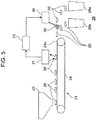
- resin flake 20 is supplied from a hopper of flake supplier 22 to flake transporter 24 as illustrated in FIG. 5 .
- Flake transporter 24 has a belt conveyor 29 and transports resin flake 20, which has been supplied from flake supplier 22, to discharge port 24a through a portion below reflectance measurer 21 by belt conveyor 29.
- Sorted flake resin collector 28 is provided at a position to which resin flake 20 discharged from discharge port 24a falls, and two flake collection containers 28a and 28b are arranged in sorted flake resin collector 28.
- Flake discriminator 26 is arranged between discharge port 24a of flake transporter 24 and sorted flake resin collector 28.
- Flake collection container 28a is arranged at a position to which resin flake 20 discharged from discharge port 24a naturally falls.
- Flake collection container 28b is arranged at a position that is closer to discharge port 24a than to flake collection container 28a.
- Flake discriminator 26 causes resin flake 20 to fall into flake collection container 28b using air pressure by blowing air 30 to resin flake 20 discharged from discharge port 24a, for example.
- Flake discriminator 26 receives an output signal from resin identification unit 23 as a control signal.
- flake discriminator 26 blows air 30 to resin flake 20 discharged from discharge port 24a. Meanwhile, in a case in which the output signal is a signal indicating another resin, flake discriminator 26 does not blow air 30 to resin flake 20 discharged from discharge port 24a.
- reflectance measurer 21 includes an irradiation optical system that irradiates resin flake 20 with infrared light and a light receiving optical system for reflected light that receives reflected light from resin flake 20 and guides the reflected light to a light detector. Further, reflectance measurer 21 includes a received light optical system for incident light that switches optical paths as needed and guides infrared light after emission from the irradiation optical system before incidence on resin flake 20 to the light detector.
- a resin determination method including:
- a resin determination apparatus including:
- Japanese Patent No. 6160475 it is possible to determine a resin type since reflected light from resin colored with a white or black color, for example, can be detected.
- a resin type of transparent resin cannot be determined since the transparent resin transmits most parts of the infrared rays.
- a resin type of transparent resin cannot be sorted with the infrared rays. Therefore, for resin pieces containing transparent resin, a visible light color hue sorting apparatus is used first to first determine a color for whether or not the resin pieces are transparent.
- a water specific gravity sorting apparatus is used to sort the resin, which has been determined to be transparent, into a resin such as PP that floats in water and the other resins, for example. To do this, a plurality of apparatuses or processes are required to sort the transparent resin, and there is also a problem that the number of types of transparent resin that can be collected is limited.
- the disclosure solves the aforementioned problems in the related art, and an object thereof is to provide resin determination method and apparatus for determining a resin type of a transparent resin using an infrared ray.
- FIG. 1 is a schematic diagram of resin determination apparatus 1 according to the embodiment.
- Resin determination apparatus 1 includes at least processor 6, infrared ray detector 8, arithmetic processor 10, and placement unit 5. Resin determination apparatus 1 performs processing on object to be sorted 2 made of an unknown material (resin type) and determines whether or not object to be sorted 2 is of a predetermined resin type using infrared light. In particular, resin determination apparatus 1 can determine the resin type of object to be sorted 2 even if object to be sorted 2 is a transparent resin. As object to be sorted 2, mainly a resin or a composite of a resin and another substance (such as metal or glass) is conceivable.
- Processor 6 has rough surface 6a with arithmetic mean roughness Ra of not less than 1.6 ⁇ m.
- Infrared ray detector 8 has irradiator 8a and light receiver 8b.
- Arithmetic processor 10 performs resin determination through arithmetic processing on the basis of received light information obtained by infrared ray detector 8.
- Placement unit 5 has sorted object placement surface 5a on which object to be sorted 2 is placed. That is, the placement surface (for example, lower surface 2c) of object to be sorted 2 is brought into contact with sorted object placement surface 5a. Placement unit 5 is implemented with a belt conveyor, for example.
- Processor 6 and infrared ray detector 8 are arranged in order from an upstream side to a downstream side of a transport direction of object to be sorted 2 relative to placement unit 5. As illustrated in FIG. 1 , processor 6 is arranged at an end of placement unit 5 on the upstream side of the transport direction in an example. Also, infrared ray detector 8 is arranged in the vicinity of an end of placement unit 5 on the downstream side of the transport direction in an example.
- FIG. 1 illustrates an example in which placement unit 5 is a belt conveyor and sorted object placement surface 5a is a belt. It is possible to transport object to be sorted 2 on sorted object placement surface 5a in the transport direction by sorted object placement surface 5a rotating (moving) at a specific speed.
- Processor 6 polishes or crushes an upper surface, for example, of object to be sorted 2. Specifically, processor 6 brings object to be sorted 2 into contact with rough surface 6a that rotates or advances and retreats in a forward-backward direction through driving of a motor or the like for a predetermined time, for example, for not less than 3 seconds. Processor 6 is arranged on an upstream side of one end of placement unit 5 along a longitudinal direction. Processor 6 supplies object to be sorted 2 after being subjected to processing to sorted object placement surface 5a at an end of placement unit 5 along the longitudinal direction. Object to be sorted 2 placed on sorted object placement surface 5a by processor 6 is transported by placement unit 5 up to detection region 7 along the longitudinal direction of placement unit 5.
- Infrared ray detector 8 includes irradiator 8a that irradiates object to be sorted 2 with irradiation light 3 (for example, infrared light) and light receiver 8b that receives reflected light 4 of irradiation light 3 after being reflected by object to be sorted 2.
- irradiation light 3 for example, infrared light
- light receiver 8b that receives reflected light 4 of irradiation light 3 after being reflected by object to be sorted 2.
- irradiator 8a is disposed above sorted object placement surface 5a of detection region 7 of placement unit 5.
- Irradiator 8a irradiates object to be sorted 2 with irradiation light 3 such as infrared light in a state in which not less than 50% of an area of an irradiation surface of object to be sorted 2 on the side of light receiver 8b is a region with arithmetic mean roughness Ra of not less than 0.025 ⁇ m.
- the reason that the proportion of the region is set to be not less than 50% of the area of the irradiation surface is to enhance determination accuracy of arithmetic processor 10.
- the region in which Ra is 0.025 ⁇ m may be the entire irradiation surface, that is, 100% of the area of the irradiation surface. This is also because the surface becomes more like a mirror surface and causes regular reflection, and sufficient reflected light 4 cannot be obtained if arithmetic mean roughness Ra is less than 0.025 ⁇ m.
- An upper limit value of arithmetic mean roughness Ra of the irradiation surface is assumed to be not more than 160 ⁇ m for practical use.
- arithmetic mean roughness Ra is not less than 0.025 ⁇ m in not less than 50% of an area of a surface on the side opposite to the irradiation surface.
- the surface of object to be sorted 2 processed by the processor 6 will be referred to as a determination target surface. That is, the determination target surface is an irradiation surface which is irradiated with infrared light or a surface on the side opposite to the irradiation surface.
- the determination target surface is upper surface 2d (irradiation surface) or lower surface 2c (the surface on the side opposite to the irradiation surface) of object to be sorted 2 placed on sorted object placement surface 5a of placement unit 5 as illustrated in FIGS. 2B and 2C as will be described later.
- the determination target surface is the placement surface of object to be sorted 2 (the surface that is brought into contact with sorted object placement surface 5a, that is, lower surface 2c) or the surface on the side opposite to the placement surface (upper surface 2d).
- a region in which object to be sorted 2 is irradiated with infrared light and object to be sorted 2 is projected onto sorted object placement surface 5a is assumed to be a projection region.
- Processing may be performed such that arithmetic mean roughness Ra is not less than 0.025 ⁇ m in the surface of object to be sorted 2 on the side of light receiver 8b or the surface on the side opposite to the aforementioned surface corresponding to not less than 50% of the area of the projection region.
- irradiation light 3 and reflected light 4 preferably include a band with a wavelength of 1 to 3 ⁇ m as an infrared light effective wavelength region.
- Light receiver 8b is disposed above sorted object placement surface 5a in detection region 7 on placement unit 5 and receives reflected light 4 from object to be sorted 2 that has been irradiated with infrared light that is irradiation light 3 from irradiator 8a.
- Arithmetic processor 10 is connected to light receiver 8b.
- arithmetic processor 10 is connected to light receiver 8b via digital data converter 9 in an example.
- Digital data converter 9 converts an electrical signal output by infrared ray detector 8 in accordance with reflected light 4 into digital data.
- Information regarding received reflected light 4 is input to arithmetic processor 10 from light receiver 8b, and arithmetic processor 10 determines a resin type of object to be sorted 2 on the basis of a reflection or absorption spectrum of object to be sorted 2 obtained from reflected light 4.
- arithmetic processor 10 has, at least, spectrum intensity acquisition unit 10a, spectrum evaluator 10b, and resin determination unit 10c.
- Spectrum intensity acquisition unit 10a calculates and acquires spectrum intensity of the reflection or absorption spectrum of object to be sorted 2 on the basis of reflected light 4 from light receiver 8b, that is, digital data output from digital data converter 9.
- analog data of reflected light 4 received by light receiver 8b is input first to spectrum intensity acquisition unit 10a of arithmetic processor 10 from light receiver 8b through digital data converter 9.
- the digital data converter 9 converts the analog data of reflected light 4 into digital data of reflected light 4, and the digital data of reflected light 4 is input to spectrum intensity acquisition unit 10a.
- Spectrum intensity acquisition unit 10a calculates reflection or absorption spectrum of object to be sorted 2 on the basis of input digital data of reflected light 4. Thereafter, spectrum intensity acquisition unit 10a refers to reference data (for example, a table format or a graph format) representing a relationship between the reflection or absorption spectrum and the spectrum intensity, for example, and generates and acquires a spectrum intensity for determining a resin corresponding to the calculated reflection or absorption spectrum.
- the reference data representing the relationship between the reflection or absorption spectrum and the spectrum intensity is created in advance using samples of known resin types. It is also possible to create the reference data representing the relationship between the reflection or absorption spectrum and the spectrum intensity while determining resin types in some cases.
- Spectrum evaluator 10b obtains a plurality of correlation information pieces between the spectrum intensity acquired by spectrum intensity acquisition unit 10a and the spectrum data of one or more resin types acquired in advance.
- the correlation information is a dimensionless quantity obtained using a correlation coefficient, regression analysis, multivariate analysis, or the like.
- Resin determination unit 10c determines correlation information that is not less than a preset threshold value and has the highest correlation in the correlation information of not less than the threshold value from among a plurality of correlation information pieces obtained by spectrum evaluator 10b as a resin type of object to be sorted 2. In a case in which all the correlation information pieces are less than the preset threshold value, it is determined that the resin is of a resin type other than the resin types corresponding to the correlation information or that determination cannot be made. The determined information can be used for the sorting and the like.
- FIG. 2A is a schematic diagram of reflection of irradiation light 3 in a case in which transparent resin 2a is placed on sorted object placement surface 55a of a black belt that is typically used using the related art.
- roughness in lower surface 2c that is a placement surface of transparent resin 2a is not adjusted, and not less than 50% of a projection area of transparent resin 2a on the side of light receiver 8b is not a region in which arithmetic mean roughness Ra is not less than 0.025 ⁇ m, for example. Therefore, irradiation light 3 is not reflected by lower surface 2c that is the placement surface of transparent resin 2a, and most parts of irradiation light 3 is transmitted without reflection.
- the determination target surface that is upper surface 2d or lower surface 2c of transparent resin 2a is processed such that not less than 50% of the projection area of transparent resin 2a on the side of light receiver 8b is a region with arithmetic mean roughness Ra of not less than 0.025 ⁇ m, using the embodiment.
- Reflected light 4 of irradiation light 3 after being reflected by upper surface 2d or lower surface 2c in a case in which upper surface 2d or lower surface 2c that is a processed surface and also a determination target surface of transparent resin 2a is then irradiated with irradiation light 3 is illustrated in the schematic diagram.
- FIG. 2D illustrates an infrared spectrum in the related art in which surface is not processed as illustrated in FIG. 2A .
- an infrared spectrum in a case in which a white polystyrene resin (PS resin) as an example of object to be sorted 2 is placed is represented as "2AW”
- an infrared spectrum in a case in which a transparent PS resin as an example of transparent resin 2a is placed is represented as "2AT”.
- FIG. 2E illustrates an infrared spectrum according to the disclosure in which the determination target surface has been processed as illustrated in FIGS. 2B and 2C .
- an infrared spectrum in a case in which a white PS resin as an example of object to be sorted 2 is placed is represented as "2BW”
- an infrared spectrum in a case in which a transparent PS resin as an example of transparent resin 2a is placed is represented as "2BT”.
- arithmetic mean roughness Ra is not less than 0.025 ⁇ m in not less than 50% of the area of the irradiation surface of transparent resin 2a on the side of light receiver 8b. Therefore, since light is reflected by the determination target surface that is upper surface 2d or lower surface 2c corresponding to the reflection surface of transparent resin 2a without being transmitted therethrough, the amount of reflected light 4 increases. Therefore, it is still possible to obtain a change in infrared spectrum that is close to that of the white PS resin (see “2BW” in FIG. 2E ) for the transparent PS resin (see “2BT” in FIG. 2E ) as illustrated as "DETERMINATION OK" in FIG.
- upper surface 2d or lower surface 2c of transparent resin 2a can reflect light regardless of whether or not upper surface 2d or lower surface 2c is in contact with sorted object placement surface 5a as illustrated in FIGS. 2B and 2C . Therefore, it is possible to make determination in a state in which contamination or scratching on sorted object placement surface 5a hardly affect the determination.
- processor 6 61, 64, 63
- FIGS. 3A to 3C examples of processor 6 (61, 64, 63) will be described with reference to FIGS. 3A to 3C .
- FIG. 3A is a schematic diagram of a method of polishing or crushing the determination target surface that is upper surface 2d or lower surface 2c of object to be sorted 2 in holding frame 61h by rotating or vibrating rough surface 61a in a planar shape using drive device 61g such as a motor.
- FIG. 3B is a schematic diagram of a method of polishing or crushing the determination target surface that is upper surface 2d or lower surface 2c of object to be sorted 2 in container 64g, in which the respective surfaces of multiple spherical balls 62 accommodated in closed container 64g are assumed to be rough surfaces 62a.
- FIG. 3C is a schematic diagram of a method of polishing or crushing the determination target surface that is upper surface 2d or lower surface 2c of object to be sorted 2 on rough surface 63a by vibrating rough surface 63a in a planar shape using drive device 63g such as a motor.
- processor 61 arranges rough surface 61a in a planar shape so as to be in contact with upper surface 2d or lower surface 2c of object to be sorted 2 and rotates or vibrates rough surface 61a. It is possible to perform polishing or crushing by bringing rough surface 61a to be rotated or vibrated into contact with upper surface 2d or lower surface 2c of object to be sorted 2 for 3 seconds or more. At this time, arithmetic mean roughness Ra in entire rough surface 61a in contact with object to be sorted 2 is preferably not less than 1.6 ⁇ m and not more than 160 ⁇ m.
- An upper limit value of a time during which rough surface 61a is brought into contact with upper surface 2d or lower surface 2c of object to be sorted 2 is 10 seconds. This is because there is a high probability that polishing destruction occurs, and object to be sorted 2 is excessively shaved if the contact time exceeds 10 seconds. Surface roughness does not change if the contact time for polishing is elongated. However, if the contact time is excessively long, shaved powder (that is, dust) increases, and the amount of object to be sorted 2 collected decreases since the entire surface is shaved.
- processor 64 has spherical ball 62 as rough surface 62a.
- Arithmetic mean roughness Ra of the surface of ball 62 is not less than 1.6 ⁇ m and not more than 160 ⁇ m. It is possible to bring rough surface 62a into contact with upper surface 2d or lower surface 2c of object to be sorted 2 for 3 seconds or more and to perform polishing or crushing by placing ball 62 and object to be sorted 2 in container 64g and rotating or vibrating entire container 64g using drive device 64h such as a motor.
- an inner surface of container 64g is preferably a rough surface with arithmetic mean roughness Ra of not less than 1.6 ⁇ m and not more than 160 ⁇ m.
- processor 63 places object to be sorted 2 such that upper surface 2d or lower surface 2c of object to be sorted 2 is brought into contact with rough surface 63a in a planar shape and applies vibration thereto as illustrated in FIG. 3C . It is possible to perform polishing or crushing by bringing rough surface 63a to which vibration is applied into contact with upper surface 2d or lower surface 2c of object to be sorted 2 for 3 seconds or more. At this time, arithmetic mean roughness Ra in entire rough surface 63a in contact with object to be sorted 2 is preferably not less than 1.6 ⁇ m and not more than 160 ⁇ m.
- arithmetic mean roughness Ra of rough surface 61a, rough surface 62a, and rough surface 63a is less than 1.6 ⁇ m, upper surface 2d or lower surface 2c of object to be sorted 2 hardly becomes a rough surface, and a sufficient reflection spectrum cannot be obtained. Also, in a case in which arithmetic mean roughness Ra of rough surface 61a, rough surface 62a, and rough surface 63a is greater than 160 ⁇ m, the rough surface of upper surface 2d and lower surface 2c of object to be sorted 2 becomes excessively rough, and a sufficient reflection spectrum cannot be obtained.
- processor 6 processes the determination target surface of object to be sorted 2 through polishing, crushing, or the like such that arithmetic mean roughness Ra is not less than 0.025 ⁇ m in at least not less than 50% of the area of the placement surface (the surface that is brought into contact with sorted object placement surface 5a) or the surface on the side opposite to the placement surface (lower surface 2c or upper surface 2d, for example) of object to be sorted 2 in Step S1.
- roughness of at least the determination target surface of the object to be sorted that is the irradiation surface (upper surface 2d) or the surface on the side opposite to the irradiation surface (lower surface 2c) of object to be sorted 2 irradiated with the infrared light is processed to set arithmetic mean roughness Ra to be not less than 0.025 ⁇ m in not less than 50% of the area of the determination target surface in Step S1.
- object to be sorted 2 is put onto placement unit 5 moving at a specific speed from processor 6, is placed on sorted object placement surface 5a of placement unit 5, and is transported up to detection region 7 in Step S2.
- infrared ray detector 8 irradiates object to be sorted 2, which has been placed on sorted object placement surface 5a and has reached detection region 7, with infrared light that is irradiation light 3 from irradiation unit 8a in Step S3.
- infrared ray detector 8 detects reflected light 4 from object to be sorted 2 that has reached detection region 7 in Step S4.
- analog data of reflected light 4 detected by infrared ray detector 8 is output from infrared ray detector 8 to arithmetic processor 10 through digital data converter 9 in Step S5.
- Digital data converter 9 converts the analog data of reflected light 4 into digital data of reflected light 4.
- Spectrum intensity acquisition unit 10a of arithmetic processor 10 calculates a reflection spectrum or an absorption spectrum of object to be sorted 2 on the basis of the input digital data of reflected light 4 and generates spectrum intensity for determining the resin on the basis of the reflection spectrum or the absorption spectrum.
- the spectrum intensity for determining the resin is output from spectrum intensity acquisition unit 10a to spectrum evaluator 10b.
- spectrum evaluator 10b calculates and evaluates a correlation coefficient between spectrum intensity for determining the resin and a sample spectrum as an example of the correlation information on the basis of the spectrum intensity for determining the resin calculated by spectrum intensity acquisition unit 10a and the sample spectrum in Step S6.
- the sample spectrum is spectrum intensity of a resin with known physical properties that have been acquired in advance.
- the calculated correlation coefficient is output from spectrum evaluator 10b to resin determination unit 10c.
- resin determination unit 10c determines a resin type of object to be sorted 2 on the basis of the correlation coefficient with the sample spectrum and a preset threshold value in Step S7. Specifically, resin determination unit 10c determines a resin type that has a correlation coefficient of not less than the threshold value and is related with the largest correlation coefficient as the resin type of object to be sorted 2.
- polishing or crushing is performed by bringing rough surface 6a of processor 6 with arithmetic mean roughness Ra of not less than 1.6 ⁇ m and not more than 160 ⁇ m into contact with lower surface 2c or upper surface 2d that is the surface of object to be sorted 2 for a predetermined time, for example, 3 seconds or more.
- arithmetic mean roughness Ra is not less than 0.025 ⁇ m in not less than 50% of the area of the projection surface of object to be sorted 2 on the light receiving side. Therefore, it is possible to reflect irradiation light 3 by the determination target surface of object to be sorted 2.
- the resin determination method and apparatus of the aforementioned aspects of the disclosure it is possible to determine a resin type of a transparent resin by receiving infrared light reflected by the determination target surface in a state in which arithmetic mean roughness Ra is not less than 0.025 ⁇ m in not less than 50% of the area of the placement surface of the transparent resin as an example of the object to be sorted (in other words, the resin determination target) or the surface on the side opposite to the placement surface.
Landscapes
- Physics & Mathematics (AREA)
- Spectroscopy & Molecular Physics (AREA)
- Life Sciences & Earth Sciences (AREA)
- Chemical & Material Sciences (AREA)
- Health & Medical Sciences (AREA)
- Pathology (AREA)
- Analytical Chemistry (AREA)
- Biochemistry (AREA)
- General Health & Medical Sciences (AREA)
- General Physics & Mathematics (AREA)
- Immunology (AREA)
- Engineering & Computer Science (AREA)
- Medicinal Chemistry (AREA)
- Food Science & Technology (AREA)
- Environmental & Geological Engineering (AREA)
- Mechanical Engineering (AREA)
- Multimedia (AREA)
- Investigating Or Analysing Materials By Optical Means (AREA)
Applications Claiming Priority (1)
| Application Number | Priority Date | Filing Date | Title |
|---|---|---|---|
| JP2018209900A JP6876983B2 (ja) | 2018-11-07 | 2018-11-07 | 樹脂判定方法及び装置 |
Publications (2)
| Publication Number | Publication Date |
|---|---|
| EP3650188A1 true EP3650188A1 (de) | 2020-05-13 |
| EP3650188B1 EP3650188B1 (de) | 2026-01-28 |
Family
ID=68382270
Family Applications (1)
| Application Number | Title | Priority Date | Filing Date |
|---|---|---|---|
| EP19205581.2A Active EP3650188B1 (de) | 2018-11-07 | 2019-10-28 | Harzbestimmungsverfahren und -vorrichtung |
Country Status (4)
| Country | Link |
|---|---|
| US (1) | US11047797B2 (de) |
| EP (1) | EP3650188B1 (de) |
| JP (1) | JP6876983B2 (de) |
| CN (1) | CN111157483B (de) |
Families Citing this family (1)
| Publication number | Priority date | Publication date | Assignee | Title |
|---|---|---|---|---|
| JP7562597B2 (ja) * | 2022-05-12 | 2024-10-07 | キヤノン株式会社 | 識別装置 |
Citations (6)
| Publication number | Priority date | Publication date | Assignee | Title |
|---|---|---|---|---|
| JPS6160475B2 (de) | 1982-01-08 | 1986-12-20 | Tokyo Shibaura Electric Co | |
| US5703681A (en) * | 1995-11-20 | 1997-12-30 | Perkin-Elmer Ltd | Carrier and its use in the preparation of samples for spectroscopy |
| EP0819929A2 (de) * | 1996-07-16 | 1998-01-21 | Perkin-Elmer Limited | Träger und dessen Anwendung bei der Aufbereitung von spektroskopischen Proben |
| WO2001086267A1 (en) * | 2000-05-10 | 2001-11-15 | Dsm N.V. | Process for identifying objects using an optical spectrometer and a transport system |
| EP3339840A1 (de) * | 2016-12-20 | 2018-06-27 | Panasonic Intellectual Property Management Co., Ltd. | Harzbestimmungsverfahren und harzbestimmungsvorrichtung |
| EP3477281A1 (de) * | 2017-10-30 | 2019-05-01 | Panasonic Intellectual Property Management Co., Ltd. | Harzbestimmungsverfahren und harzbestimmungsvorrichtung |
Family Cites Families (20)
| Publication number | Priority date | Publication date | Assignee | Title |
|---|---|---|---|---|
| JPH09105724A (ja) * | 1995-08-04 | 1997-04-22 | Kobe Steel Ltd | 表面検査装置 |
| JP2000329702A (ja) * | 1999-03-18 | 2000-11-30 | Toray Ind Inc | シートの欠陥検出装置 |
| JP2000338013A (ja) * | 1999-05-25 | 2000-12-08 | Shimadzu Corp | 拡散反射光測定用試料サンプラ |
| JP2002131310A (ja) * | 2000-10-25 | 2002-05-09 | Sony Corp | プラスチックの判別対象部位の再生装置およびプラスチックの判別対象部位の再生方法 |
| JP2002286637A (ja) | 2001-03-27 | 2002-10-03 | Matsushita Electric Ind Co Ltd | プラスチックの識別装置 |
| JP4113549B2 (ja) | 2003-07-18 | 2008-07-09 | 松下電器産業株式会社 | プラスチック識別装置およびプラスチック識別方法 |
| JP2005070009A (ja) * | 2003-08-28 | 2005-03-17 | Toyota Motor Corp | 分光分析装置 |
| JP4903808B2 (ja) * | 2007-05-01 | 2012-03-28 | パナソニック株式会社 | 樹脂の分別方法 |
| JP4946652B2 (ja) * | 2007-06-18 | 2012-06-06 | 富士通株式会社 | 元素測定方法および試料削り取り装置 |
| JP5210586B2 (ja) * | 2007-10-01 | 2013-06-12 | Idec株式会社 | プラスチック判別装置およびプラスチック判別方法 |
| JP2009115503A (ja) * | 2007-11-02 | 2009-05-28 | Lasertec Corp | 粗さ測定方法及び粗さ測定装置 |
| JP5179229B2 (ja) * | 2008-03-11 | 2013-04-10 | 日東電工株式会社 | レーザーポインタ視認性向上フィルム、偏光板、画像表示装置およびレーザーポインタ表示方法 |
| WO2012035785A1 (ja) | 2010-09-17 | 2012-03-22 | パナソニック株式会社 | 臭素系難燃剤判定方法、臭素系難燃剤判定装置、リサイクル方法、及び、リサイクル装置 |
| JP2012132804A (ja) * | 2010-12-22 | 2012-07-12 | Kyoto Univ | 光増強素子 |
| DE102011102430A1 (de) * | 2011-05-24 | 2012-11-29 | Schott Ag | Optischer Durchflusssensor |
| JP5901453B2 (ja) * | 2011-08-26 | 2016-04-13 | 三菱電機株式会社 | 樹脂識別装置および方法 |
| JP6137987B2 (ja) * | 2013-01-21 | 2017-05-31 | 三菱電機株式会社 | 樹脂種識別方法および樹脂種識別装置 |
| JP6160475B2 (ja) | 2013-12-25 | 2017-07-12 | 株式会社島津製作所 | 樹脂識別方法および装置 |
| CN205607884U (zh) * | 2016-05-16 | 2016-09-28 | 福建出入境检验检疫局检验检疫技术中心 | 一种带有红外感应的皮革检测装置 |
| JP6597981B2 (ja) * | 2017-03-06 | 2019-10-30 | Jfeスチール株式会社 | 表面検査装置の異常判定方法とその表面検査装置 |
-
2018
- 2018-11-07 JP JP2018209900A patent/JP6876983B2/ja active Active
-
2019
- 2019-10-25 US US16/664,448 patent/US11047797B2/en active Active
- 2019-10-28 EP EP19205581.2A patent/EP3650188B1/de active Active
- 2019-10-30 CN CN201911051412.7A patent/CN111157483B/zh active Active
Patent Citations (6)
| Publication number | Priority date | Publication date | Assignee | Title |
|---|---|---|---|---|
| JPS6160475B2 (de) | 1982-01-08 | 1986-12-20 | Tokyo Shibaura Electric Co | |
| US5703681A (en) * | 1995-11-20 | 1997-12-30 | Perkin-Elmer Ltd | Carrier and its use in the preparation of samples for spectroscopy |
| EP0819929A2 (de) * | 1996-07-16 | 1998-01-21 | Perkin-Elmer Limited | Träger und dessen Anwendung bei der Aufbereitung von spektroskopischen Proben |
| WO2001086267A1 (en) * | 2000-05-10 | 2001-11-15 | Dsm N.V. | Process for identifying objects using an optical spectrometer and a transport system |
| EP3339840A1 (de) * | 2016-12-20 | 2018-06-27 | Panasonic Intellectual Property Management Co., Ltd. | Harzbestimmungsverfahren und harzbestimmungsvorrichtung |
| EP3477281A1 (de) * | 2017-10-30 | 2019-05-01 | Panasonic Intellectual Property Management Co., Ltd. | Harzbestimmungsverfahren und harzbestimmungsvorrichtung |
Non-Patent Citations (3)
| Title |
|---|
| ABRAHAM V�ZQUEZ-GUARDADO ET AL: "Multi-spectral infrared spectroscopy for robust plastic identification", APPLIED OPTICS, vol. 54, no. 24, 18 August 2015 (2015-08-18), WASHINGTON, DC; US, pages 7396, XP055537507, ISSN: 0003-6935, DOI: 10.1364/AO.54.007396 * |
| FLORESTAN J ET AL: "RECYCLING OF PLASTICS: AUTOMATIC IDENTIFICATION OF POLYMERS BY SPECTROSCOPIC METHODS", RESOURCES, CONSERVATION AND RECYCLING, ELSEVIER, AMSTERDAM, NL, vol. 10, no. 1/02, 1 April 1994 (1994-04-01), pages 67 - 74, XP000442597, ISSN: 0921-3449, DOI: 10.1016/0921-3449(94)90039-6 * |
| MADAN KUMAR L ET AL: "Design of an embedded based control system for efficient sorting of waste plastics using Near Infrared Spectroscopy", 2014 IEEE INTERNATIONAL CONFERENCE ON ELECTRONICS, COMPUTING AND COMMUNICATION TECHNOLOGIES (CONECCT), IEEE, 6 January 2014 (2014-01-06), pages 1 - 6, XP032567351, DOI: 10.1109/CONECCT.2014.6740338 * |
Also Published As
| Publication number | Publication date |
|---|---|
| CN111157483A (zh) | 2020-05-15 |
| CN111157483B (zh) | 2022-08-23 |
| US11047797B2 (en) | 2021-06-29 |
| EP3650188B1 (de) | 2026-01-28 |
| US20200141865A1 (en) | 2020-05-07 |
| JP6876983B2 (ja) | 2021-05-26 |
| JP2020076636A (ja) | 2020-05-21 |
Similar Documents
| Publication | Publication Date | Title |
|---|---|---|
| EP3477281B1 (de) | Harzbestimmungsverfahren und harzbestimmungsvorrichtung | |
| JP3307968B2 (ja) | 物質分離方法及び装置 | |
| CN1014456B (zh) | 鉴别污染与未污染容器的方法 | |
| EP3339840A1 (de) | Harzbestimmungsverfahren und harzbestimmungsvorrichtung | |
| JP2007505733A (ja) | 廃棄物の流れ中の目標物を分類する装置および方法 | |
| EP3650188B1 (de) | Harzbestimmungsverfahren und -vorrichtung | |
| JP2021128062A (ja) | 廃プラスチックの材質判定装置、材質判定方法、及び材質判定プログラム | |
| Tan et al. | Identification for recycling polyethylene terephthalate (pet) plastic bottles by polarization vision | |
| JPH10122969A (ja) | プラスチック製物品の分別方法 | |
| JPH08300354A (ja) | プラスチック分別装置 | |
| EP3477282B1 (de) | Verfahren und vorrichtung zur bestimmung von harzfarbe | |
| JP5229204B2 (ja) | プラスチックの識別装置およびその識別方法 | |
| EP1955012B1 (de) | Verfahren und vorrichtung zum überprüfen der seitenwandkontur eines behälters | |
| CN108971026A (zh) | 一种废弃塑料种类的分选装置及其分选方法 | |
| WO2019056402A1 (zh) | 一种基于灰度状态序列的送料分选装置 | |
| WO2004101178A1 (en) | Plastic automatic separation apparatus and the automatic separation method | |
| US20170343472A1 (en) | Specific bromine-based flame retardant determination method and determination apparatus | |
| JP2001074650A (ja) | プラスチック判別法 | |
| Marchesi et al. | COMPARATIVE STUDY OF CHEMOMETRIC APPROACHES AND MACHINE LEARNING FOR MINIATURIZED NEAR-INFRARED (MICRONIR) SPECTROSCOPY IN PLASTIC WASTE SORTING | |
| JP6435930B2 (ja) | 樹脂種識別装置 | |
| CN114226271B (zh) | 一种原矿抛分方法、装置、终端设备及介质 | |
| JP2002303575A (ja) | 識別装置及び選別装置 | |
| JP2023182993A (ja) | 樹脂判定方法 | |
| Cesetti et al. | Near infrared technology for material identification and selection | |
| JP2016024175A (ja) | 試料分析装置 |
Legal Events
| Date | Code | Title | Description |
|---|---|---|---|
| PUAI | Public reference made under article 153(3) epc to a published international application that has entered the european phase |
Free format text: ORIGINAL CODE: 0009012 |
|
| STAA | Information on the status of an ep patent application or granted ep patent |
Free format text: STATUS: THE APPLICATION HAS BEEN PUBLISHED |
|
| AK | Designated contracting states |
Kind code of ref document: A1 Designated state(s): AL AT BE BG CH CY CZ DE DK EE ES FI FR GB GR HR HU IE IS IT LI LT LU LV MC MK MT NL NO PL PT RO RS SE SI SK SM TR |
|
| AX | Request for extension of the european patent |
Extension state: BA ME |
|
| STAA | Information on the status of an ep patent application or granted ep patent |
Free format text: STATUS: REQUEST FOR EXAMINATION WAS MADE |
|
| 17P | Request for examination filed |
Effective date: 20200914 |
|
| RBV | Designated contracting states (corrected) |
Designated state(s): AL AT BE BG CH CY CZ DE DK EE ES FI FR GB GR HR HU IE IS IT LI LT LU LV MC MK MT NL NO PL PT RO RS SE SI SK SM TR |
|
| STAA | Information on the status of an ep patent application or granted ep patent |
Free format text: STATUS: EXAMINATION IS IN PROGRESS |
|
| 17Q | First examination report despatched |
Effective date: 20210416 |
|
| GRAP | Despatch of communication of intention to grant a patent |
Free format text: ORIGINAL CODE: EPIDOSNIGR1 |
|
| STAA | Information on the status of an ep patent application or granted ep patent |
Free format text: STATUS: GRANT OF PATENT IS INTENDED |
|
| INTG | Intention to grant announced |
Effective date: 20250828 |
|
| GRAS | Grant fee paid |
Free format text: ORIGINAL CODE: EPIDOSNIGR3 |
|
| GRAA | (expected) grant |
Free format text: ORIGINAL CODE: 0009210 |
|
| STAA | Information on the status of an ep patent application or granted ep patent |
Free format text: STATUS: THE PATENT HAS BEEN GRANTED |
|
| AK | Designated contracting states |
Kind code of ref document: B1 Designated state(s): AL AT BE BG CH CY CZ DE DK EE ES FI FR GB GR HR HU IE IS IT LI LT LU LV MC MK MT NL NO PL PT RO RS SE SI SK SM TR |
|
| REG | Reference to a national code |
Ref country code: CH Ref legal event code: F10 Free format text: ST27 STATUS EVENT CODE: U-0-0-F10-F00 (AS PROVIDED BY THE NATIONAL OFFICE) Effective date: 20260128 Ref country code: GB Ref legal event code: FG4D |
|
| REG | Reference to a national code |
Ref country code: DE Ref legal event code: R096 Ref document number: 602019080601 Country of ref document: DE |
|
| REG | Reference to a national code |
Ref country code: IE Ref legal event code: FG4D |