EP3650719A2 - Dispositif palier, palier à joint à rotule et dispositif pourvu d'un dispositif palier et d'au moins un palier à billes - Google Patents
Dispositif palier, palier à joint à rotule et dispositif pourvu d'un dispositif palier et d'au moins un palier à billes Download PDFInfo
- Publication number
- EP3650719A2 EP3650719A2 EP19202676.3A EP19202676A EP3650719A2 EP 3650719 A2 EP3650719 A2 EP 3650719A2 EP 19202676 A EP19202676 A EP 19202676A EP 3650719 A2 EP3650719 A2 EP 3650719A2
- Authority
- EP
- European Patent Office
- Prior art keywords
- bearing
- ball
- arrangement
- ball joint
- bracket
- Prior art date
- Legal status (The legal status is an assumption and is not a legal conclusion. Google has not performed a legal analysis and makes no representation as to the accuracy of the status listed.)
- Granted
Links
Images




Classifications
-
- F—MECHANICAL ENGINEERING; LIGHTING; HEATING; WEAPONS; BLASTING
- F16—ENGINEERING ELEMENTS AND UNITS; GENERAL MEASURES FOR PRODUCING AND MAINTAINING EFFECTIVE FUNCTIONING OF MACHINES OR INSTALLATIONS; THERMAL INSULATION IN GENERAL
- F16C—SHAFTS; FLEXIBLE SHAFTS; ELEMENTS OR CRANKSHAFT MECHANISMS; ROTARY BODIES OTHER THAN GEARING ELEMENTS; BEARINGS
- F16C11/00—Pivots; Pivotal connections
- F16C11/04—Pivotal connections
- F16C11/06—Ball-joints; Other joints having more than one degree of angular freedom, i.e. universal joints
- F16C11/0685—Manufacture of ball-joints and parts thereof, e.g. assembly of ball-joints
- F16C11/069—Manufacture of ball-joints and parts thereof, e.g. assembly of ball-joints with at least one separate part to retain the ball member in the socket; Quick-release systems
-
- F—MECHANICAL ENGINEERING; LIGHTING; HEATING; WEAPONS; BLASTING
- F16—ENGINEERING ELEMENTS AND UNITS; GENERAL MEASURES FOR PRODUCING AND MAINTAINING EFFECTIVE FUNCTIONING OF MACHINES OR INSTALLATIONS; THERMAL INSULATION IN GENERAL
- F16C—SHAFTS; FLEXIBLE SHAFTS; ELEMENTS OR CRANKSHAFT MECHANISMS; ROTARY BODIES OTHER THAN GEARING ELEMENTS; BEARINGS
- F16C11/00—Pivots; Pivotal connections
- F16C11/04—Pivotal connections
- F16C11/06—Ball-joints; Other joints having more than one degree of angular freedom, i.e. universal joints
- F16C11/0619—Ball-joints; Other joints having more than one degree of angular freedom, i.e. universal joints the female part comprising a blind socket receiving the male part
- F16C11/0623—Construction or details of the socket member
-
- B—PERFORMING OPERATIONS; TRANSPORTING
- B60—VEHICLES IN GENERAL
- B60H—ARRANGEMENTS OF HEATING, COOLING, VENTILATING OR OTHER AIR-TREATING DEVICES SPECIALLY ADAPTED FOR PASSENGER OR GOODS SPACES OF VEHICLES
- B60H1/00—Heating, cooling or ventilating devices
- B60H1/34—Nozzles; Air-diffusers
-
- B—PERFORMING OPERATIONS; TRANSPORTING
- B60—VEHICLES IN GENERAL
- B60H—ARRANGEMENTS OF HEATING, COOLING, VENTILATING OR OTHER AIR-TREATING DEVICES SPECIALLY ADAPTED FOR PASSENGER OR GOODS SPACES OF VEHICLES
- B60H1/00—Heating, cooling or ventilating devices
- B60H1/34—Nozzles; Air-diffusers
- B60H1/3414—Nozzles; Air-diffusers with means for adjusting the air stream direction
-
- F—MECHANICAL ENGINEERING; LIGHTING; HEATING; WEAPONS; BLASTING
- F16—ENGINEERING ELEMENTS AND UNITS; GENERAL MEASURES FOR PRODUCING AND MAINTAINING EFFECTIVE FUNCTIONING OF MACHINES OR INSTALLATIONS; THERMAL INSULATION IN GENERAL
- F16C—SHAFTS; FLEXIBLE SHAFTS; ELEMENTS OR CRANKSHAFT MECHANISMS; ROTARY BODIES OTHER THAN GEARING ELEMENTS; BEARINGS
- F16C11/00—Pivots; Pivotal connections
- F16C11/04—Pivotal connections
- F16C11/06—Ball-joints; Other joints having more than one degree of angular freedom, i.e. universal joints
- F16C11/0604—Construction of the male part
-
- F—MECHANICAL ENGINEERING; LIGHTING; HEATING; WEAPONS; BLASTING
- F16—ENGINEERING ELEMENTS AND UNITS; GENERAL MEASURES FOR PRODUCING AND MAINTAINING EFFECTIVE FUNCTIONING OF MACHINES OR INSTALLATIONS; THERMAL INSULATION IN GENERAL
- F16C—SHAFTS; FLEXIBLE SHAFTS; ELEMENTS OR CRANKSHAFT MECHANISMS; ROTARY BODIES OTHER THAN GEARING ELEMENTS; BEARINGS
- F16C11/00—Pivots; Pivotal connections
- F16C11/04—Pivotal connections
- F16C11/06—Ball-joints; Other joints having more than one degree of angular freedom, i.e. universal joints
- F16C11/0614—Ball-joints; Other joints having more than one degree of angular freedom, i.e. universal joints the female part of the joint being open on two sides
-
- F—MECHANICAL ENGINEERING; LIGHTING; HEATING; WEAPONS; BLASTING
- F16—ENGINEERING ELEMENTS AND UNITS; GENERAL MEASURES FOR PRODUCING AND MAINTAINING EFFECTIVE FUNCTIONING OF MACHINES OR INSTALLATIONS; THERMAL INSULATION IN GENERAL
- F16C—SHAFTS; FLEXIBLE SHAFTS; ELEMENTS OR CRANKSHAFT MECHANISMS; ROTARY BODIES OTHER THAN GEARING ELEMENTS; BEARINGS
- F16C11/00—Pivots; Pivotal connections
- F16C11/04—Pivotal connections
- F16C11/06—Ball-joints; Other joints having more than one degree of angular freedom, i.e. universal joints
- F16C11/0619—Ball-joints; Other joints having more than one degree of angular freedom, i.e. universal joints the female part comprising a blind socket receiving the male part
- F16C11/0623—Construction or details of the socket member
- F16C11/0657—Construction or details of the socket member the socket member being mainly made of plastics
-
- F—MECHANICAL ENGINEERING; LIGHTING; HEATING; WEAPONS; BLASTING
- F16—ENGINEERING ELEMENTS AND UNITS; GENERAL MEASURES FOR PRODUCING AND MAINTAINING EFFECTIVE FUNCTIONING OF MACHINES OR INSTALLATIONS; THERMAL INSULATION IN GENERAL
- F16C—SHAFTS; FLEXIBLE SHAFTS; ELEMENTS OR CRANKSHAFT MECHANISMS; ROTARY BODIES OTHER THAN GEARING ELEMENTS; BEARINGS
- F16C11/00—Pivots; Pivotal connections
- F16C11/04—Pivotal connections
- F16C11/06—Ball-joints; Other joints having more than one degree of angular freedom, i.e. universal joints
- F16C11/0695—Mounting of ball-joints, e.g. fixing them to a connecting rod
-
- F—MECHANICAL ENGINEERING; LIGHTING; HEATING; WEAPONS; BLASTING
- F16—ENGINEERING ELEMENTS AND UNITS; GENERAL MEASURES FOR PRODUCING AND MAINTAINING EFFECTIVE FUNCTIONING OF MACHINES OR INSTALLATIONS; THERMAL INSULATION IN GENERAL
- F16C—SHAFTS; FLEXIBLE SHAFTS; ELEMENTS OR CRANKSHAFT MECHANISMS; ROTARY BODIES OTHER THAN GEARING ELEMENTS; BEARINGS
- F16C11/00—Pivots; Pivotal connections
- F16C11/04—Pivotal connections
- F16C11/10—Arrangements for locking
- F16C11/103—Arrangements for locking frictionally clamped
- F16C11/106—Arrangements for locking frictionally clamped for ball joints
-
- B—PERFORMING OPERATIONS; TRANSPORTING
- B60—VEHICLES IN GENERAL
- B60H—ARRANGEMENTS OF HEATING, COOLING, VENTILATING OR OTHER AIR-TREATING DEVICES SPECIALLY ADAPTED FOR PASSENGER OR GOODS SPACES OF VEHICLES
- B60H1/00—Heating, cooling or ventilating devices
- B60H1/34—Nozzles; Air-diffusers
- B60H2001/3471—Details of actuators
- B60H2001/3478—Details of actuators acting on additional damper doors
-
- F—MECHANICAL ENGINEERING; LIGHTING; HEATING; WEAPONS; BLASTING
- F16—ENGINEERING ELEMENTS AND UNITS; GENERAL MEASURES FOR PRODUCING AND MAINTAINING EFFECTIVE FUNCTIONING OF MACHINES OR INSTALLATIONS; THERMAL INSULATION IN GENERAL
- F16C—SHAFTS; FLEXIBLE SHAFTS; ELEMENTS OR CRANKSHAFT MECHANISMS; ROTARY BODIES OTHER THAN GEARING ELEMENTS; BEARINGS
- F16C2226/00—Joining parts; Fastening; Assembling or mounting parts
- F16C2226/50—Positive connections
- F16C2226/70—Positive connections with complementary interlocking parts
- F16C2226/74—Positive connections with complementary interlocking parts with snap-fit, e.g. by clips
Definitions
- a bearing arrangement, a ball joint bearing and an arrangement with a bearing arrangement and at least one ball joint bearing are described. Such an arrangement enables a rotary movement to be transmitted via the coupling rod.
- control wheels are often provided which serve to pivot air guiding elements or air flaps to control the amount of air supplied.
- Air vents are used to expel and deflect air provided by an air conditioner or other ventilation device. Air vents are used in vehicles to bring fresh air, tempered air and / or conditioned air into the passenger compartment of a vehicle. Vehicles can be, for example, motor vehicles, such as cars, trucks or buses, trains, planes or ships. In the case of air vents, in addition to controlling the deflection of air that is output, for example from an air conditioning system, the amount of air that is output can also be regulated. The amount of air supplied is regulated by a control device, which, for example an operating device for pivoting slats or separately from such an operating device is arranged next to an outflow opening. Air vents can be arranged in a vehicle dashboard or in the area of the A, B or C pillar or on the roof of a motor vehicle.
- a closing flap for regulating the amount of air supplied is often pivoted via an operating wheel.
- the transmission of the rotary movement of the control wheel to a lever that is coupled to the closing flap is usually carried out via a coupling rod.
- the coupling rod has bearing balls which are accommodated in bearing points of the control wheel and the lever.
- a rotatable control element on an air vent with a ball joint which consists of a ball segment and a ball socket.
- the ball segment is integrally formed on the housing and the ball socket on the control wheel, the ball segment being provided on the operating wheel side with two coaxially formed approaches which are arranged opposite one another in the direction of the longitudinal extent of the housing.
- the lugs have a distance of about 0.2 mm from an inner base of the ball socket in the direction of a bearing axis and form a stop for this.
- the ball socket itself is made up of four coaxially arranged elastically expandable pan segments with a spherical spherical surface. Due to the design, the control wheel can be tilted about 2 ° relative to the normal to the bearing axis, which provides a small tolerance compensation.
- a solution is to be specified that is robust against improper handling during transport, during assembly and in use, provides an angular compensation of non-coaxially aligned axes of rotation of a control wheel and a closing flap, enables a process-reliable design and ensures a setup without coordination.
- a bearing arrangement with at least one first connecting section, the at least one first connecting section having a bearing ball and an extension extending from the bearing ball, which is flat on the side facing the bearing ball and on the opposite side facing away from the bearing ball , is rounded.
- the extension on the bearing ball provides protection against unintentional disengagement after the bearing ball has been received in a corresponding ball joint bearing.
- the extension also offers the advantage that angular compensation of non-coaxial axes of rotation of a control wheel and a closing flap can be achieved without the bearing balls sliding out or "jumping out”. The extension prevents the bearing ball from coming out.
- the bearing arrangement can be arranged both on a coupling rod and on an operating wheel and / or a lever of a closing flap control.
- the bearing arrangement can also have two connecting sections, each of which has a bearing ball.
- the bearing arrangement can have further connection sections, each with a bearing ball, in still further versions.
- the bearing ball has at least three sections (I., II., III.) Between a central plane intersecting the bearing ball and an opposite end, which have an increasing diameter towards the central plane, the at least three sections having a non-homogeneous course .
- a normal sphere has a homogeneous curve with a constant curvature on its surface.
- the bearing ball with the at least three sections has no homogeneous course.
- the sections have transitions with a curvature or radius that is smaller or larger than the curvature or radius of the ball.
- the curvature can take place in the opposite direction, so that the sections themselves are, for example, concave, the ball itself having a convex curvature.
- the contour of the bearing balls prevents a component (eg coupling rod) connected to the bearing arrangement from tipping over against the influence of gravity. Controlled axial centering is also provided.
- the contour of the bearing ball provides, in particular, a transition between increasing bearing point diameters, the bearing point diameter increasing as the deviating angle increases.
- the extension can be designed as a mushroom head.
- a mushroom head enables easy insertion into a ball joint bearing and offers a locking mechanism against unintentional disengagement via the flat side.
- a coupling rod can each have a connecting section at the end sections.
- the end sections of the coupling rod can be offset with respect to one another in the longitudinal direction.
- the coupling rod is then particularly suitable, for example, for designs which do not have coaxially aligned axes of rotation and / or the rotation points of an operating wheel and a lever are offset from one another.
- ball joint bearings as described below, on the end sections of a coupling rod with offset end sections.
- an end section can have a bearing arrangement with a first connecting section and the other end section of a coupling rod can have a ball joint bearing.
- a ball-and-socket joint bearing for receiving a bearing ball, comprising two arms which run parallel to one another and are spring-mounted on a base, the arms each having a bulge which together form a bearing point for a bearing ball, the bearing point having at least two pairs of opposing ones Has bearing surfaces, which are arranged on the arms in the region of the bulges, and wherein after the bearing point, apart from the base, one arm has a bracket which surrounds an opposite arm section of the other arm.
- the ball joint bearing already provides play compensation and tolerance compensation through the two spring-loaded arms.
- the arrangement of the opposite pairs of bearing surfaces has at least four contact points, via which a bearing ball is received within the bearing point.
- the bearing surfaces of the pairs of opposite bearing surfaces can preferably be designed such that they lie opposite each other both on the two arms and on a plane running through the bearing point, so that with two opposite pairs of bearing surfaces essentially a four-point bearing or with three opposite pairs of bearing surfaces essentially a six-point bearing is achieved. This allows further clearance compensation and tolerance compensation.
- bracket and the arm section provide a safeguard against unintentional disengagement and prevent excessive deformation of the ball joint bearing when a bearing ball snaps into place and thus counteract damage.
- the spring-loaded design of the arms also enables the mounting of bearing balls with diameters that have a larger tolerance range.
- the bracket which secures the arm section against shifting too far, even enables the image to be significantly enlarged Bearing balls without causing damage to the ball joint bearing.
- the bracket and the inner arm section surrounded by the bracket can have a first undercut in the sliding direction, the sliding direction running essentially parallel to the extension of the arm section of the inner arm surrounded by the bracket.
- the first undercut is formed by surfaces on the bracket and on the arm section, which lie against one another when force is applied in the sliding direction and thus limit the displacement of the bracket relative to the arm in the sliding direction. This prevents the bracket and arm section from sliding apart during assembly.
- the bracket and the inner arm section surrounded by the bracket can have a second undercut in the mounting direction, the mounting direction running parallel to the opening through the bearing point.
- the second undercut is formed by opposite surfaces on the bracket and on the inner arm section.
- a first bearing surface of a pair of opposing bearing surfaces can be arranged on the bulge of a first arm and a second bearing surface can be arranged on the bulge of a second arm.
- the opposite bearing surfaces of a pair of bearing surfaces are designed such that they each lie on different arms or in the bulges of the two arms and face each other.
- At least one pair of opposing bearing surfaces has an elevation which is formed on the bulge of one of the arms.
- a pair of opposing bearing surfaces can preferably have two elevations, each of the elevations being arranged on a bulge of the opposing arms.
- the elevations are aligned with one another in such a way that they provide opposing contact surfaces.
- the bearing point is designed in such a way that the three pairs of opposing bearing surfaces are designed such that the pairs of opposing bearing surfaces each have two elevations which are arranged on the opposite bulges of the two arms and are aligned with one another.
- the six-point bearing designed in this way also provides tolerance and play compensation for different bearing balls.
- the sprung arrangement of the two arms also allows the use of larger tolerances in the manufacture of ball and socket bearings.
- the inner arm section can be a distance between the inner arm section and the bracket, so that the deflection of at least one arm provides additional tolerance compensation.
- the spring-loaded arms can be pressed apart, the size of the bearing balls accommodated in the bearing point being able to vary more than is achieved by known designs in the prior art.
- the distance between the bracket and the inner arm section can accordingly define the extent to which the arms can slide apart.
- the ball joint bearing can be arranged, for example, on an operating wheel and / or a lever of a closing flap control.
- at least one ball joint bearing can also be arranged on a coupling rod, preferably on an end section,
- the above-mentioned object is also achieved by an arrangement with a bearing arrangement according to one of the variants described above and at least one ball joint bearing according to one of the variants described above, wherein at least one bearing ball of the bearing arrangement is received in the bearing point of the ball joint bearing and the bearing ball on the bearing surfaces of the Bearing position is present.
- the bearing arrangement can preferably also have two bearing balls which are arranged on the opposite end sections in a first connecting section and in a second connecting section (for example coupling rod).
- a coupling rod can be connected to a lever which has a ball joint bearing, the lever being connected to a closing flap. A pivoting of the lever or a twisting of the lever around a bearing of the lever then causes the closing flap to pivot.
- the ball joint bearing of the lever is radially spaced from the bearing of the lever.
- the coupling rod can be coupled to an operating wheel via the second connecting section.
- the control wheel has a bearing around which the control wheel is rotatably mounted.
- the control wheel has a ball joint bearing that is radially spaced from the bearing of the control wheel.
- the control wheel has an adjustment section on an outer peripheral edge. The adjustment section is used to turn the control wheel.
- the ball joint bearings of the control wheel and the lever transmit the rotation of the control wheel to the lever via the coupling rod, so that turning the control wheel causes the closing flap to pivot.
- the formation of the spherical joint bearings and the bearing ball of the coupling rod enable a play compensation and a tolerance compensation.
- the components of such an arrangement, coupling rod, ball joint bearing as well as control wheel and lever, can consist of plastic and can therefore be produced inexpensively and quickly in large numbers in an injection molding process.
- additives can be added to the plastic during manufacture and / or reinforcing inserts can be used.
- Fig. 1 shows a schematic representation of an arrangement 100, consisting of a coupling rod 10, an operating wheel 30 and a lever 20.
- the arrangement 100 serves to adjust the orientation of a closing flap of an air vent in a vehicle.
- the lever 20 is coupled via a bearing 22 to a section which runs transversely to the closing flap and runs through the pivot axis of the closing flap.
- the bearing 22 defines the pivot axis of the closing flap and the pivot axis of the lever 20.
- the operating wheel 30 is rotatably mounted on the housing of the air vent by a bearing 32 and has a front section which serves to pivot the operating wheel 30.
- the front section is in the representation of Fig. 1 on the left.
- the front section can be provided with further elements in order to form an adjustment section.
- the adjustment section can be illuminated. Rotation of the control wheel 30 about the axis of rotation, which runs through the bearing 32, leads to a corresponding pivoting of the lever 20 via the coupling rod 10.
- the air vent is connected to a ventilation device, such as. B. an air conditioning system can be connected.
- the amount of air supplied can be controlled via the closing flap.
- the control wheel 30 and the lever 20 have ball joint bearings 40, which are designed to receive bearing balls 16 of the coupling rod 10.
- the coupling rod 10 has bearing arrangements with a first connecting section 12 and a second at its opposite end sections Connection section 14.
- the coupling rod 10 has two bearing arrangements, each with a bearing arrangement that has a connecting section.
- a bearing arrangement can also have two connecting sections.
- the coupling rod 10 is connected to the ball joint bearing 40 of the lever 20 via the first connecting section 12.
- the coupling rod 10 is connected to the ball joint bearing 40 of the control wheel 30 via the second connecting section 14. Rotation of the control wheel 30 therefore leads to a pivoting of the closing flap which is connected to the lever 20.
- Fig. 1 shows the arrangement 100 in a first position, wherein the control wheel 30 can be rotated clockwise around the bearing 32. This leads to a pivoting of the lever 20, whereby rotation about the bearing 22 takes place counterclockwise.
- the ball joint bearings 40 of the lever 20 and the control wheel 30 are constructed essentially the same and are described with reference to FIG 6 - 8 described.
- Fig. 2 shows a side view of the arrangement 100 of FIG Fig. 1 .
- the coupling rod 10 has in the first connecting section 12 and the second connecting section 14 the bearing balls 16, which are received in bearing points 46 of the ball joint bearings 40. Extensions in the form of mushroom heads 18 protrude from the bearing balls 60 and provide protection against unintentional disengagement.
- Fig. 3 13 shows a top view of the arrangement 100 of FIG Fig. 1 .
- the bearing balls 16 are connected to the connection points 12 and 14 by means of pins 19. Between the flat underside of the mushroom head 18 and the bearing balls 18 another distance.
- the mushroom heads 18 By means of the mushroom heads 18 and securing them against disengagement, it is possible to provide angular compensation for the axes of rotation of the lever 20 and the control wheel 30 which are not coaxially mounted, without disengagement occurring.
- the first connection section 12 and the second connection section 14 cannot be as in FIG Fig.
- Fig. 4 shows a schematic representation of the coupling rod 10 of the arrangement 100.
- the coupling rod 10 has a web 11, on the opposite ends of which the first connecting section 12 and the second connecting section 14 are arranged.
- Each of the connecting sections 12 and 14 has a pin 19 on which a bearing ball 16 is arranged.
- a mushroom head 18 is arranged at a distance from the bearing balls 16.
- Fig. 5 shows a side view of the coupling rod 10.
- the bearing balls 16 are designed so that they have three sections.
- the bearing balls 16 have a corresponding contour.
- the contour of the two bearing balls 16 in interaction prevents the coupling rod 10 from tipping over against the influence of gravity and also offers a controlled axial centering between the two bearing points in the first connecting section 12 and in the second connecting section 14.
- the contour of the bearing balls 16 provides a transition between increasing bearing point diameters .
- the ideal Bearing diameter in the first section I Provided.
- the bearing point diameter in the second section II increases continuously and braces the coupling rod 10 with a centering effect.
- the largest bearing diameter is in the third section III. provided.
- the alignment of the coupling rod 10 therefore remains the same in all positions of the coupling rod 10 and positions of the control wheel 30 and the lever 20.
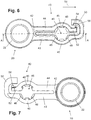
- Fig. 6 shows a schematic representation of the lever 20 of the arrangement 100.
- the ball joint bearing 40 has a base 42.
- the base 42 forms the starting point and the connection point to, for example, the lever 20 Fig. 6
- a base 42 could also be configured in some other way.
- a base 42 always results, however, since the arms 43, 44 extending from the base 42 must be connected in some form to another component.
- the arms 43, 44 extend from the base 42 in a first section parallel to one another and then merge into a section with a bulge 45.
- a bearing point 46 is defined between the opposite bulges 45.
- the bearing point 46 serves to receive a bearing ball 16 of the coupling rod 10.
- a bracket 50 extends from the bulge 45 of the first arm 43 and surrounds an arm section 52 of the second arm 44.
- the bracket 50 is formed spaced apart from the arm section 52.
- the arms 43 and 44 are spring-loaded so that when a bearing ball is inserted into the bearing 46, the arms 43, 44, especially in the region of the bulges 45, can be pressed apart in order to receive a bearing ball 16 in the bearing 46 between the bearing surfaces 48.
- the distance between the bracket 50 and the arm section 52 allows the arms 43, 44 to be spread apart to a certain extent.
- the distance between the arm section 52 and the bracket 50 in a direction orthogonal to a sliding direction 56 also specifies the maximum size of the bearing ball accommodated in the bearing point 46.
- a first undercut 54 is also formed by corresponding surfaces on the bracket 50 and the arm section 52.
- the first undercut 54 prevents them from sliding apart, since the opposite surfaces of the first undercut 54 can come into contact with the arm 50 and the arm section 52.
- the first undercut 54 prevents it from sliding apart in the sliding direction 56.
- bracket 50 and the arm section 52 have a second undercut 58, which is formed by likewise opposite surfaces on the bracket 50 and on the arm section 52 (see here Fig. 7 , 8th ).
- the second undercut 58 is aligned in the mounting direction 59.
- the second undercut 58 is formed by opposite surfaces on the bracket 50 on the arm section 52.
- Fig. 7 shows a further illustration of the lever 20 of the arrangement 100.
- Fig. 7 shows the rear view of the representation of Fig. 6 .
- the surface of the second undercut 58 on the arm section 52 can come into contact with the surface of the second undercut 58 on the bracket 50 when the bearing ball 16 is introduced (see Fig. 6 ). This limits the sliding apart to a maximum.
- the opposing surfaces on the arm section 52 and on the bracket 50 of the second undercut 58 are at a distance from one another. The same applies to the opposite surfaces of the first undercut 54 on the arm section 52 and on the bracket 50.
- the ball joint bearing 40 thus offers tolerance compensation in different directions and also prevents play in the bearing points 46.
- Fig. 8 shows an enlarged representation of the ball joint bearing 40 of the lever 20.
- the representation shows the formation of the second undercut 58 on the arm portion 52 and the formation of the elevations for forming the bearing surfaces 48.
- the bearing surfaces 48 are designed as inclined bearings (see also here Fig. 9 ) and have a curvature for mounting the bearing ball 16.
- the mushroom head 18 is first introduced into the bearing 46 in the mounting direction 59.
- the rounded design of the mushroom head 18 at the outer end facilitates the insertion into the bearing 46 and the widening of the bearing 46, the arm section 52 being bent open until the opposite surfaces of the first undercut 54 abut one another. After the bearing 46 has expanded to the maximum, the mushroom head 18 can emerge from the bearing 46 again.
- the bearing ball 16 While the mushroom head 18 widens the bearing point with its rounded upper side, the bearing ball 16 already reaches the bearing point 46. After the mushroom head 18 has emerged, the bearing ball 16 is therefore received within the bearing point 46 between the bearing surfaces 48. During the insertion of the mushroom head 18 and the bearing ball 16, the opposing surfaces come into contact with the arm section 52 and the bracket 50 of the second undercut 58 and prevent the arms 43, 44 from sliding off flat underside of the mushroom head 18 opposite the bearing 46. The flat underside prevents the bearing ball 16 from disengaging. The bearing ball 16 is securely received within the bearing 46 via the three pairs of opposing bearing surfaces 48 and cannot disengage since the mushroom head 18 prevents disengagement.
- the spring-loaded mounting of the arms 43, 44 also offers play compensation and enables compliance with larger tolerances in the production of the coupling rod 10 and the ball joint bearing 40. Frequent tool changes in injection molding tools are therefore not necessary and simplify the manufacturing process. In particular, this results in enormous cost savings.
- Fig. 9 shows a sectional view of the lever 20 along the sectional plane AA of FIG Fig. 6 .
- the bearing 22 of the lever 20 has an opening 24.
- a pin of a closing flap is received via the opening 24 and locked with the lever 20, so that pivoting of the lever 20 also causes the closing flap to pivot.
- Fig. 9 each shows a bearing surface 48 of the three pairs of opposite bearing surfaces. It can be seen from the illustration that tolerance compensation is provided via the six-point bearing in cooperation with the sprung design of the arms 43, 44, because bearing balls 16 with different diameters are always received in the center of the bearing 46 and the sprung arms 43, 44 center the bearing balls hold.
- Fig. 10 shows a schematic representation of the control wheel 30 of the arrangement 100.
- the ball joint bearing 40 of the control wheel 30 differs from the ball joint bearing 40 of the lever 20 in the orientation of the arm section 52 and the bracket 50 and the specific design of the bulges 45.
- the bulge 45 of the arm 43 extends by a larger amount around the bearing point 46 than the bulge 45 of the second arm 44.
- the mode of action of the ball joint bearing 40 is identical to the ball joint bearing 40 of the lever 20, so that a play compensation and a tolerance compensation are also provided.
- Fig. 11 shows a side view of a bearing ball 16 with pin 19 and mushroom head 18 and a section through the bearing ball 16, pin 19 and mushroom head 18.
- the bearing ball 16 has as in relation to Fig. 5 already indicated three sections.
- the first section I. represents the ideal bearing point diameter in a neutral position of the coupling rod 10.
- the bearing ball 16 has an essentially linear increase.
- the bearing point diameter increases in the second section II.
- the third section III. also have an enlarged bearing diameter.
- the sectional view on the right shows the formation of the transitions and the individual sections I., II. And III.
- the radius R6 indicates the radius of the bearing ball 16 starting from the center of the ball 16.
- the radius R3 indicates the radius in the transition between the first section I and II.
- the contour of the bearing ball 16 essentially runs between the radii R3 and R1 or R5.
- the center points for the radii R1 and R5 lie on an imaginary circle that in Fig. 11 is represented by the schematically indicated small circle (chain line).
- the centers of the radii R2 and R4 lie on an imaginary circle that in Fig. 11 the bearing ball 16 surrounds from the outside (chain line).
- the contour of the bearing ball 16 runs between the two schematically indicated circles, which are designed as dotted lines.
- the contour of the bearing ball 16 differs from conventional bearing balls in that no homogeneous, constant course is provided over the entire surface of the bearing ball.
- the individual sections I., II., III. enable an increase in the bearing point diameter with an alignment of the coupling rod 10, with no tilting.
- the contour for this is decisive and essentially forms a "groove" for the bearing 46 of the ball joint bearings 40. As soon as the bearing 46 arrives outside the optimal position in the first section I, the coupling rod 10 is aligned via the enlarged bearing diameter.
- the bearing ball 16 is designed such that the contour is formed both between a central plane running through the bearing ball 16 and the mushroom head 18 and between this central plane and the pin 19. Furthermore, a further second section II extends over the first section I. This leads to an alignment of the coupling rod 10 being achieved even when the bearing point 46 is deflected upward. The bearing ball 16 therefore enables alignment and centering in both directions and counteracts tipping due to the influence of gravity.
- the contour of the bearing ball 16 can be easily formed by plastic.
- the advantages that can be achieved by the contour are that there is no blockage can come and thus the function of a shutter control is maintained.
Landscapes
- Engineering & Computer Science (AREA)
- General Engineering & Computer Science (AREA)
- Mechanical Engineering (AREA)
- Physics & Mathematics (AREA)
- Thermal Sciences (AREA)
- Pivots And Pivotal Connections (AREA)
Priority Applications (1)
| Application Number | Priority Date | Filing Date | Title |
|---|---|---|---|
| EP21153515.8A EP3832154B1 (fr) | 2018-10-16 | 2019-10-11 | Élément palier pour une rotule et ensemble à rotule avec un élément palier |
Applications Claiming Priority (1)
| Application Number | Priority Date | Filing Date | Title |
|---|---|---|---|
| DE102018125619.1A DE102018125619A1 (de) | 2018-10-16 | 2018-10-16 | Lageranordnung, Kugelgelenklager und Anordnung mit einer Lageranordnung und mindestens einem Kugelgelenklager |
Related Child Applications (2)
| Application Number | Title | Priority Date | Filing Date |
|---|---|---|---|
| EP21153515.8A Division EP3832154B1 (fr) | 2018-10-16 | 2019-10-11 | Élément palier pour une rotule et ensemble à rotule avec un élément palier |
| EP21153515.8A Division-Into EP3832154B1 (fr) | 2018-10-16 | 2019-10-11 | Élément palier pour une rotule et ensemble à rotule avec un élément palier |
Publications (3)
| Publication Number | Publication Date |
|---|---|
| EP3650719A2 true EP3650719A2 (fr) | 2020-05-13 |
| EP3650719A3 EP3650719A3 (fr) | 2020-07-29 |
| EP3650719B1 EP3650719B1 (fr) | 2022-04-20 |
Family
ID=68280812
Family Applications (2)
| Application Number | Title | Priority Date | Filing Date |
|---|---|---|---|
| EP21153515.8A Active EP3832154B1 (fr) | 2018-10-16 | 2019-10-11 | Élément palier pour une rotule et ensemble à rotule avec un élément palier |
| EP19202676.3A Active EP3650719B1 (fr) | 2018-10-16 | 2019-10-11 | Dispositif palier, palier à joint à rotule et dispositif pourvu d'un dispositif palier et d'au moins un palier à billes |
Family Applications Before (1)
| Application Number | Title | Priority Date | Filing Date |
|---|---|---|---|
| EP21153515.8A Active EP3832154B1 (fr) | 2018-10-16 | 2019-10-11 | Élément palier pour une rotule et ensemble à rotule avec un élément palier |
Country Status (3)
| Country | Link |
|---|---|
| EP (2) | EP3832154B1 (fr) |
| CN (1) | CN111059142B (fr) |
| DE (1) | DE102018125619A1 (fr) |
Citations (1)
| Publication number | Priority date | Publication date | Assignee | Title |
|---|---|---|---|---|
| DE102009051297A1 (de) | 2009-01-09 | 2010-07-15 | Volkswagen Ag | Lagerung eines drehbaren Bedienelements an einem Luftausströmer |
Family Cites Families (23)
| Publication number | Priority date | Publication date | Assignee | Title |
|---|---|---|---|---|
| US57061A (en) * | 1866-08-14 | Improvement in pitman-boxes | ||
| DE8314774U1 (de) | 1983-11-10 | K.K.P. Konstruktive Kunststoff-Produkte Handelsgesellschaft Mbh, 8744 Mellrichstadt | Kugelgelenk zum Verbinden von stangen- und/oder hebelförmigen Betätigungselementen | |
| FR1146639A (fr) | 1955-04-20 | 1957-11-13 | Ehrenreich & Cie A | Articulation à rotule, destinée en particulier aux timoneries de direction |
| DE1196434B (de) * | 1959-09-25 | 1965-07-08 | Bosch Gmbh Robert | Kugelgelenk zum Verbinden von Gestaengeteilen |
| DE1625581B2 (de) | 1967-12-07 | 1971-11-25 | Springfix- Befestigungstechnik Gmbh, 7335 Salach | Kugelgelenk zum verbinden von gestaengeteilen |
| IT987181B (it) | 1973-05-03 | 1975-02-20 | Magneti Marelli Spa | Snodo sferico per trasmissioni di limitata potenza in particolare per tergicristallo di autoveicoli |
| DE2420241A1 (de) | 1974-04-26 | 1975-11-06 | Bosch Gmbh Robert | Antriebsgestaengeteil |
| US4360284A (en) * | 1980-10-08 | 1982-11-23 | General Motors Corporation | Ball-joint assembly |
| DE3712460A1 (de) * | 1987-04-11 | 1988-10-20 | Trw Ehrenreich Gmbh | Kugelgelenk |
| JPS63195116U (fr) | 1987-06-02 | 1988-12-15 | ||
| IT1213631B (it) | 1987-09-25 | 1989-12-29 | Pier Giorgio Fumagalli | Snodo sferico a guscio integrale semi aperto e con chiusura ad anello agganciabile, per tiranterie ad ancoraggio ortogonale. |
| WO1995033139A1 (fr) * | 1994-05-31 | 1995-12-07 | Itt Automotive Electrical Systems, Inc. | Rotule d'articulation a chapeau solidaire |
| GB2326190A (en) * | 1997-06-14 | 1998-12-16 | Ford Motor Co | A ball joint |
| CN101421139A (zh) * | 2006-04-10 | 2009-04-29 | 卢克摩擦片和离合器两合公司 | 活塞杆连接装置 |
| CN101408219B (zh) * | 2007-10-12 | 2013-04-24 | 鸿富锦精密工业(深圳)有限公司 | 转动定位结构 |
| JP5704991B2 (ja) * | 2011-03-29 | 2015-04-22 | ダイキョーニシカワ株式会社 | レジスタ |
| DE102013209493A1 (de) * | 2013-05-22 | 2014-11-27 | Behr Gmbh & Co. Kg | Gelenkverbindung |
| DE102014105359B4 (de) * | 2013-06-14 | 2017-07-27 | Dr. Schneider Kunststoffwerke Gmbh | Einrichtung zum Steuern von ausströmender Luft aus einem Luftausströmer |
| KR101584020B1 (ko) * | 2014-12-11 | 2016-01-08 | 주식회사 니프코코리아 | 자동차용 에어벤트 |
| DE202016002952U1 (de) * | 2016-05-10 | 2017-08-11 | GM Global Technology Operations LLC (n. d. Ges. d. Staates Delaware) | Luftfausströmer zur Anordnung im Innenraum eines Kraftfahrzeugs |
| CN206374514U (zh) * | 2016-12-19 | 2017-08-04 | 重庆众科科技有限公司 | 一种空调出风口拨动机构 |
| BR112019013958A2 (pt) * | 2017-01-06 | 2020-02-11 | Robert Bosch Gmbh | Junta esférica com conjunto de soquete esférico de travamento |
| KR20190049290A (ko) * | 2017-11-01 | 2019-05-09 | 현대모비스 주식회사 | 차량용 에어벤트 |
-
2018
- 2018-10-16 DE DE102018125619.1A patent/DE102018125619A1/de not_active Withdrawn
-
2019
- 2019-10-11 EP EP21153515.8A patent/EP3832154B1/fr active Active
- 2019-10-11 EP EP19202676.3A patent/EP3650719B1/fr active Active
- 2019-10-16 CN CN201910981925.1A patent/CN111059142B/zh active Active
Patent Citations (1)
| Publication number | Priority date | Publication date | Assignee | Title |
|---|---|---|---|---|
| DE102009051297A1 (de) | 2009-01-09 | 2010-07-15 | Volkswagen Ag | Lagerung eines drehbaren Bedienelements an einem Luftausströmer |
Also Published As
| Publication number | Publication date |
|---|---|
| CN111059142A (zh) | 2020-04-24 |
| EP3832154A1 (fr) | 2021-06-09 |
| DE102018125619A1 (de) | 2020-04-16 |
| CN111059142B (zh) | 2022-08-02 |
| EP3650719B1 (fr) | 2022-04-20 |
| EP3650719A3 (fr) | 2020-07-29 |
| EP3832154B1 (fr) | 2022-04-13 |
Similar Documents
| Publication | Publication Date | Title |
|---|---|---|
| EP2208633B1 (fr) | Structure en ciseaux pour un siège de véhicule, siège de véhicule, notamment siège de véhicule automobile, et procédé de fabrication d'un bâti d'un siège de véhicule | |
| EP3692269B1 (fr) | Accouplement angulaire | |
| DE202008011318U1 (de) | Befestigungsanordnung mit Toleranzausgleich | |
| DE102009043578B3 (de) | Verschiebegelenk | |
| EP3870465B1 (fr) | Ensemble de paliers et diffuseur d'air comprenant un ensemble de paliers de ce type | |
| EP3381725B1 (fr) | Aérateur | |
| EP3017207B1 (fr) | Élément intérieur et galet de joint homocinétique de type tripode | |
| EP1531290B1 (fr) | Dispositif de sélection de vitesse | |
| EP3832154B1 (fr) | Élément palier pour une rotule et ensemble à rotule avec un élément palier | |
| DE19860336A1 (de) | Vorrichtung zur Steuerung eines Luftstromes insbesondere in einem Kraftfahrzeugkühler | |
| DE19860337A1 (de) | Vorrichtung zur Verbindung von translationsbeweglichen Elementen und Luftstrom-Steuervorrichtung mit einer solchen Verbindungsvorrichtung | |
| DE102018118234B4 (de) | Luftausströmer | |
| DE102020102971B4 (de) | Gelenkteil mit einem Lagerelement | |
| DE10233932A1 (de) | Mechanisches Verbindungselement und Verfahren zu seiner Herstellung | |
| EP1262693B1 (fr) | Tige de commande de fourchettes avec fourchette de commande de changement de vitesses | |
| EP2287484A2 (fr) | Ensemble moyeu-arbre pour la transmission de couple | |
| DE2210177A1 (de) | Schwenklager fuer eine im zuge einer leitung eingesetzte klappe | |
| DE102012209058A1 (de) | Scheibenwischvorrichtung | |
| EP3626491B1 (fr) | Composant palier et dispositif palier doté d'un composant palier notamment pour un clapet d'obturation d'un aérateur | |
| EP3946991A1 (fr) | Dispositif de couplage entre un élément de guidage d'air et un dispositif d'entraînement, et diffuseur d'air doté d'un ensemble de lamelles | |
| EP2581614A2 (fr) | Module de basculement de sphère | |
| DE102014200282A1 (de) | Schnappverbindungsstruktur für eine Scheibenwischergestängeanordnung und Scheibenwischer | |
| DE102008053660B4 (de) | Nabe für einen Beschlag eines Fahrzeugsitzes, Beschlag für einen Fahrzeugsitz und Welle-Nabe-Anordnung für einen Beschlag eines Fahrzeugsitzes | |
| DE102010046887A1 (de) | Verschiebegelenk | |
| DE102018126016A1 (de) | Koppelanordnung und Luftausströmer mit einer Koppelanordnung |
Legal Events
| Date | Code | Title | Description |
|---|---|---|---|
| PUAI | Public reference made under article 153(3) epc to a published international application that has entered the european phase |
Free format text: ORIGINAL CODE: 0009012 |
|
| STAA | Information on the status of an ep patent application or granted ep patent |
Free format text: STATUS: THE APPLICATION HAS BEEN PUBLISHED |
|
| AK | Designated contracting states |
Kind code of ref document: A2 Designated state(s): AL AT BE BG CH CY CZ DE DK EE ES FI FR GB GR HR HU IE IS IT LI LT LU LV MC MK MT NL NO PL PT RO RS SE SI SK SM TR |
|
| AX | Request for extension of the european patent |
Extension state: BA ME |
|
| PUAL | Search report despatched |
Free format text: ORIGINAL CODE: 0009013 |
|
| AK | Designated contracting states |
Kind code of ref document: A3 Designated state(s): AL AT BE BG CH CY CZ DE DK EE ES FI FR GB GR HR HU IE IS IT LI LT LU LV MC MK MT NL NO PL PT RO RS SE SI SK SM TR |
|
| AX | Request for extension of the european patent |
Extension state: BA ME |
|
| RIC1 | Information provided on ipc code assigned before grant |
Ipc: F16C 11/06 20060101AFI20200623BHEP Ipc: B60H 1/34 20060101ALI20200623BHEP |
|
| STAA | Information on the status of an ep patent application or granted ep patent |
Free format text: STATUS: REQUEST FOR EXAMINATION WAS MADE |
|
| 17P | Request for examination filed |
Effective date: 20210126 |
|
| RBV | Designated contracting states (corrected) |
Designated state(s): AL AT BE BG CH CY CZ DE DK EE ES FI FR GB GR HR HU IE IS IT LI LT LU LV MC MK MT NL NO PL PT RO RS SE SI SK SM TR |
|
| GRAP | Despatch of communication of intention to grant a patent |
Free format text: ORIGINAL CODE: EPIDOSNIGR1 |
|
| STAA | Information on the status of an ep patent application or granted ep patent |
Free format text: STATUS: GRANT OF PATENT IS INTENDED |
|
| INTG | Intention to grant announced |
Effective date: 20211206 |
|
| GRAS | Grant fee paid |
Free format text: ORIGINAL CODE: EPIDOSNIGR3 |
|
| GRAA | (expected) grant |
Free format text: ORIGINAL CODE: 0009210 |
|
| STAA | Information on the status of an ep patent application or granted ep patent |
Free format text: STATUS: THE PATENT HAS BEEN GRANTED |
|
| AK | Designated contracting states |
Kind code of ref document: B1 Designated state(s): AL AT BE BG CH CY CZ DE DK EE ES FI FR GB GR HR HU IE IS IT LI LT LU LV MC MK MT NL NO PL PT RO RS SE SI SK SM TR |
|
| REG | Reference to a national code |
Ref country code: GB Ref legal event code: FG4D Free format text: NOT ENGLISH |
|
| REG | Reference to a national code |
Ref country code: CH Ref legal event code: EP |
|
| REG | Reference to a national code |
Ref country code: IE Ref legal event code: FG4D Free format text: LANGUAGE OF EP DOCUMENT: GERMAN |
|
| REG | Reference to a national code |
Ref country code: DE Ref legal event code: R096 Ref document number: 502019004104 Country of ref document: DE |
|
| REG | Reference to a national code |
Ref country code: AT Ref legal event code: REF Ref document number: 1485363 Country of ref document: AT Kind code of ref document: T Effective date: 20220515 |
|
| REG | Reference to a national code |
Ref country code: LT Ref legal event code: MG9D |
|
| REG | Reference to a national code |
Ref country code: NL Ref legal event code: MP Effective date: 20220420 |
|
| PG25 | Lapsed in a contracting state [announced via postgrant information from national office to epo] |
Ref country code: NL Free format text: LAPSE BECAUSE OF FAILURE TO SUBMIT A TRANSLATION OF THE DESCRIPTION OR TO PAY THE FEE WITHIN THE PRESCRIBED TIME-LIMIT Effective date: 20220420 |
|
| PG25 | Lapsed in a contracting state [announced via postgrant information from national office to epo] |
Ref country code: SE Free format text: LAPSE BECAUSE OF FAILURE TO SUBMIT A TRANSLATION OF THE DESCRIPTION OR TO PAY THE FEE WITHIN THE PRESCRIBED TIME-LIMIT Effective date: 20220420 Ref country code: PT Free format text: LAPSE BECAUSE OF FAILURE TO SUBMIT A TRANSLATION OF THE DESCRIPTION OR TO PAY THE FEE WITHIN THE PRESCRIBED TIME-LIMIT Effective date: 20220822 Ref country code: NO Free format text: LAPSE BECAUSE OF FAILURE TO SUBMIT A TRANSLATION OF THE DESCRIPTION OR TO PAY THE FEE WITHIN THE PRESCRIBED TIME-LIMIT Effective date: 20220720 Ref country code: LT Free format text: LAPSE BECAUSE OF FAILURE TO SUBMIT A TRANSLATION OF THE DESCRIPTION OR TO PAY THE FEE WITHIN THE PRESCRIBED TIME-LIMIT Effective date: 20220420 Ref country code: HR Free format text: LAPSE BECAUSE OF FAILURE TO SUBMIT A TRANSLATION OF THE DESCRIPTION OR TO PAY THE FEE WITHIN THE PRESCRIBED TIME-LIMIT Effective date: 20220420 Ref country code: GR Free format text: LAPSE BECAUSE OF FAILURE TO SUBMIT A TRANSLATION OF THE DESCRIPTION OR TO PAY THE FEE WITHIN THE PRESCRIBED TIME-LIMIT Effective date: 20220721 Ref country code: FI Free format text: LAPSE BECAUSE OF FAILURE TO SUBMIT A TRANSLATION OF THE DESCRIPTION OR TO PAY THE FEE WITHIN THE PRESCRIBED TIME-LIMIT Effective date: 20220420 Ref country code: ES Free format text: LAPSE BECAUSE OF FAILURE TO SUBMIT A TRANSLATION OF THE DESCRIPTION OR TO PAY THE FEE WITHIN THE PRESCRIBED TIME-LIMIT Effective date: 20220420 Ref country code: BG Free format text: LAPSE BECAUSE OF FAILURE TO SUBMIT A TRANSLATION OF THE DESCRIPTION OR TO PAY THE FEE WITHIN THE PRESCRIBED TIME-LIMIT Effective date: 20220720 |
|
| PG25 | Lapsed in a contracting state [announced via postgrant information from national office to epo] |
Ref country code: RS Free format text: LAPSE BECAUSE OF FAILURE TO SUBMIT A TRANSLATION OF THE DESCRIPTION OR TO PAY THE FEE WITHIN THE PRESCRIBED TIME-LIMIT Effective date: 20220420 Ref country code: PL Free format text: LAPSE BECAUSE OF FAILURE TO SUBMIT A TRANSLATION OF THE DESCRIPTION OR TO PAY THE FEE WITHIN THE PRESCRIBED TIME-LIMIT Effective date: 20220420 Ref country code: LV Free format text: LAPSE BECAUSE OF FAILURE TO SUBMIT A TRANSLATION OF THE DESCRIPTION OR TO PAY THE FEE WITHIN THE PRESCRIBED TIME-LIMIT Effective date: 20220420 Ref country code: IS Free format text: LAPSE BECAUSE OF FAILURE TO SUBMIT A TRANSLATION OF THE DESCRIPTION OR TO PAY THE FEE WITHIN THE PRESCRIBED TIME-LIMIT Effective date: 20220820 |
|
| REG | Reference to a national code |
Ref country code: DE Ref legal event code: R097 Ref document number: 502019004104 Country of ref document: DE |
|
| PG25 | Lapsed in a contracting state [announced via postgrant information from national office to epo] |
Ref country code: SM Free format text: LAPSE BECAUSE OF FAILURE TO SUBMIT A TRANSLATION OF THE DESCRIPTION OR TO PAY THE FEE WITHIN THE PRESCRIBED TIME-LIMIT Effective date: 20220420 Ref country code: SK Free format text: LAPSE BECAUSE OF FAILURE TO SUBMIT A TRANSLATION OF THE DESCRIPTION OR TO PAY THE FEE WITHIN THE PRESCRIBED TIME-LIMIT Effective date: 20220420 Ref country code: RO Free format text: LAPSE BECAUSE OF FAILURE TO SUBMIT A TRANSLATION OF THE DESCRIPTION OR TO PAY THE FEE WITHIN THE PRESCRIBED TIME-LIMIT Effective date: 20220420 Ref country code: EE Free format text: LAPSE BECAUSE OF FAILURE TO SUBMIT A TRANSLATION OF THE DESCRIPTION OR TO PAY THE FEE WITHIN THE PRESCRIBED TIME-LIMIT Effective date: 20220420 Ref country code: DK Free format text: LAPSE BECAUSE OF FAILURE TO SUBMIT A TRANSLATION OF THE DESCRIPTION OR TO PAY THE FEE WITHIN THE PRESCRIBED TIME-LIMIT Effective date: 20220420 Ref country code: CZ Free format text: LAPSE BECAUSE OF FAILURE TO SUBMIT A TRANSLATION OF THE DESCRIPTION OR TO PAY THE FEE WITHIN THE PRESCRIBED TIME-LIMIT Effective date: 20220420 |
|
| PLBE | No opposition filed within time limit |
Free format text: ORIGINAL CODE: 0009261 |
|
| STAA | Information on the status of an ep patent application or granted ep patent |
Free format text: STATUS: NO OPPOSITION FILED WITHIN TIME LIMIT |
|
| 26N | No opposition filed |
Effective date: 20230123 |
|
| PG25 | Lapsed in a contracting state [announced via postgrant information from national office to epo] |
Ref country code: AL Free format text: LAPSE BECAUSE OF FAILURE TO SUBMIT A TRANSLATION OF THE DESCRIPTION OR TO PAY THE FEE WITHIN THE PRESCRIBED TIME-LIMIT Effective date: 20220420 |
|
| PG25 | Lapsed in a contracting state [announced via postgrant information from national office to epo] |
Ref country code: SI Free format text: LAPSE BECAUSE OF FAILURE TO SUBMIT A TRANSLATION OF THE DESCRIPTION OR TO PAY THE FEE WITHIN THE PRESCRIBED TIME-LIMIT Effective date: 20220420 Ref country code: MC Free format text: LAPSE BECAUSE OF FAILURE TO SUBMIT A TRANSLATION OF THE DESCRIPTION OR TO PAY THE FEE WITHIN THE PRESCRIBED TIME-LIMIT Effective date: 20220420 |
|
| REG | Reference to a national code |
Ref country code: CH Ref legal event code: PL |
|
| REG | Reference to a national code |
Ref country code: BE Ref legal event code: MM Effective date: 20221031 |
|
| PG25 | Lapsed in a contracting state [announced via postgrant information from national office to epo] |
Ref country code: LU Free format text: LAPSE BECAUSE OF NON-PAYMENT OF DUE FEES Effective date: 20221011 |
|
| P01 | Opt-out of the competence of the unified patent court (upc) registered |
Effective date: 20230525 |
|
| PG25 | Lapsed in a contracting state [announced via postgrant information from national office to epo] |
Ref country code: LI Free format text: LAPSE BECAUSE OF NON-PAYMENT OF DUE FEES Effective date: 20221031 Ref country code: CH Free format text: LAPSE BECAUSE OF NON-PAYMENT OF DUE FEES Effective date: 20221031 |
|
| PG25 | Lapsed in a contracting state [announced via postgrant information from national office to epo] |
Ref country code: BE Free format text: LAPSE BECAUSE OF NON-PAYMENT OF DUE FEES Effective date: 20221031 |
|
| PG25 | Lapsed in a contracting state [announced via postgrant information from national office to epo] |
Ref country code: IE Free format text: LAPSE BECAUSE OF NON-PAYMENT OF DUE FEES Effective date: 20221011 |
|
| PG25 | Lapsed in a contracting state [announced via postgrant information from national office to epo] |
Ref country code: IT Free format text: LAPSE BECAUSE OF FAILURE TO SUBMIT A TRANSLATION OF THE DESCRIPTION OR TO PAY THE FEE WITHIN THE PRESCRIBED TIME-LIMIT Effective date: 20220420 |
|
| PG25 | Lapsed in a contracting state [announced via postgrant information from national office to epo] |
Ref country code: HU Free format text: LAPSE BECAUSE OF FAILURE TO SUBMIT A TRANSLATION OF THE DESCRIPTION OR TO PAY THE FEE WITHIN THE PRESCRIBED TIME-LIMIT; INVALID AB INITIO Effective date: 20191011 |
|
| PG25 | Lapsed in a contracting state [announced via postgrant information from national office to epo] |
Ref country code: CY Free format text: LAPSE BECAUSE OF FAILURE TO SUBMIT A TRANSLATION OF THE DESCRIPTION OR TO PAY THE FEE WITHIN THE PRESCRIBED TIME-LIMIT Effective date: 20220420 |
|
| PG25 | Lapsed in a contracting state [announced via postgrant information from national office to epo] |
Ref country code: MK Free format text: LAPSE BECAUSE OF FAILURE TO SUBMIT A TRANSLATION OF THE DESCRIPTION OR TO PAY THE FEE WITHIN THE PRESCRIBED TIME-LIMIT Effective date: 20220420 |
|
| PG25 | Lapsed in a contracting state [announced via postgrant information from national office to epo] |
Ref country code: MT Free format text: LAPSE BECAUSE OF FAILURE TO SUBMIT A TRANSLATION OF THE DESCRIPTION OR TO PAY THE FEE WITHIN THE PRESCRIBED TIME-LIMIT Effective date: 20220420 |
|
| PG25 | Lapsed in a contracting state [announced via postgrant information from national office to epo] |
Ref country code: BG Free format text: LAPSE BECAUSE OF FAILURE TO SUBMIT A TRANSLATION OF THE DESCRIPTION OR TO PAY THE FEE WITHIN THE PRESCRIBED TIME-LIMIT Effective date: 20220420 |
|
| PG25 | Lapsed in a contracting state [announced via postgrant information from national office to epo] |
Ref country code: BG Free format text: LAPSE BECAUSE OF FAILURE TO SUBMIT A TRANSLATION OF THE DESCRIPTION OR TO PAY THE FEE WITHIN THE PRESCRIBED TIME-LIMIT Effective date: 20220420 |
|
| REG | Reference to a national code |
Ref country code: DE Ref legal event code: R081 Ref document number: 502019004104 Country of ref document: DE Owner name: MOTHERSON DRSC DEUTSCHLAND GMBH, DE Free format text: FORMER OWNER: DR. SCHNEIDER KUNSTSTOFFWERKE GMBH, 96317 KRONACH, DE |
|
| REG | Reference to a national code |
Ref country code: GB Ref legal event code: 732E Free format text: REGISTERED BETWEEN 20250724 AND 20250730 |
|
| PG25 | Lapsed in a contracting state [announced via postgrant information from national office to epo] |
Ref country code: TR Free format text: LAPSE BECAUSE OF FAILURE TO SUBMIT A TRANSLATION OF THE DESCRIPTION OR TO PAY THE FEE WITHIN THE PRESCRIBED TIME-LIMIT Effective date: 20220420 |
|
| REG | Reference to a national code |
Ref country code: AT Ref legal event code: MM01 Ref document number: 1485363 Country of ref document: AT Kind code of ref document: T Effective date: 20241011 |
|
| PGFP | Annual fee paid to national office [announced via postgrant information from national office to epo] |
Ref country code: DE Payment date: 20250226 Year of fee payment: 7 |
|
| PGFP | Annual fee paid to national office [announced via postgrant information from national office to epo] |
Ref country code: GB Payment date: 20251024 Year of fee payment: 7 |
|
| PG25 | Lapsed in a contracting state [announced via postgrant information from national office to epo] |
Ref country code: AT Free format text: LAPSE BECAUSE OF NON-PAYMENT OF DUE FEES Effective date: 20241011 |
|
| PGFP | Annual fee paid to national office [announced via postgrant information from national office to epo] |
Ref country code: FR Payment date: 20251027 Year of fee payment: 7 |
|
| PGFP | Annual fee paid to national office [announced via postgrant information from national office to epo] |
Ref country code: AT Payment date: 20260410 Year of fee payment: 5 |