EP3650764A1 - Climatiseur - Google Patents
Climatiseur Download PDFInfo
- Publication number
- EP3650764A1 EP3650764A1 EP19207975.4A EP19207975A EP3650764A1 EP 3650764 A1 EP3650764 A1 EP 3650764A1 EP 19207975 A EP19207975 A EP 19207975A EP 3650764 A1 EP3650764 A1 EP 3650764A1
- Authority
- EP
- European Patent Office
- Prior art keywords
- refrigerant
- air conditioner
- heat exchanger
- channel
- compressor
- Prior art date
- Legal status (The legal status is an assumption and is not a legal conclusion. Google has not performed a legal analysis and makes no representation as to the accuracy of the status listed.)
- Granted
Links
Images




Classifications
-
- F—MECHANICAL ENGINEERING; LIGHTING; HEATING; WEAPONS; BLASTING
- F24—HEATING; RANGES; VENTILATING
- F24F—AIR-CONDITIONING; AIR-HUMIDIFICATION; VENTILATION; USE OF AIR CURRENTS FOR SCREENING
- F24F1/00—Room units for air-conditioning, e.g. separate or self-contained units or units receiving primary air from a central station
- F24F1/06—Separate outdoor units, e.g. outdoor unit to be linked to a separate room comprising a compressor and a heat exchanger
- F24F1/14—Heat exchangers specially adapted for separate outdoor units
- F24F1/16—Arrangement or mounting thereof
-
- F—MECHANICAL ENGINEERING; LIGHTING; HEATING; WEAPONS; BLASTING
- F25—REFRIGERATION OR COOLING; COMBINED HEATING AND REFRIGERATION SYSTEMS; HEAT PUMP SYSTEMS; MANUFACTURE OR STORAGE OF ICE; LIQUEFACTION SOLIDIFICATION OF GASES
- F25B—REFRIGERATION MACHINES, PLANTS OR SYSTEMS; COMBINED HEATING AND REFRIGERATION SYSTEMS; HEAT PUMP SYSTEMS
- F25B41/00—Fluid-circulation arrangements
- F25B41/40—Fluid line arrangements
-
- F—MECHANICAL ENGINEERING; LIGHTING; HEATING; WEAPONS; BLASTING
- F24—HEATING; RANGES; VENTILATING
- F24F—AIR-CONDITIONING; AIR-HUMIDIFICATION; VENTILATION; USE OF AIR CURRENTS FOR SCREENING
- F24F1/00—Room units for air-conditioning, e.g. separate or self-contained units or units receiving primary air from a central station
- F24F1/0003—Room units for air-conditioning, e.g. separate or self-contained units or units receiving primary air from a central station characterised by a split arrangement, wherein parts of the air-conditioning system, e.g. evaporator and condenser, are in separately located units
-
- F—MECHANICAL ENGINEERING; LIGHTING; HEATING; WEAPONS; BLASTING
- F24—HEATING; RANGES; VENTILATING
- F24F—AIR-CONDITIONING; AIR-HUMIDIFICATION; VENTILATION; USE OF AIR CURRENTS FOR SCREENING
- F24F1/00—Room units for air-conditioning, e.g. separate or self-contained units or units receiving primary air from a central station
- F24F1/0007—Indoor units, e.g. fan coil units
- F24F1/0068—Indoor units, e.g. fan coil units characterised by the arrangement of refrigerant piping outside the heat exchanger within the unit casing
-
- F—MECHANICAL ENGINEERING; LIGHTING; HEATING; WEAPONS; BLASTING
- F24—HEATING; RANGES; VENTILATING
- F24F—AIR-CONDITIONING; AIR-HUMIDIFICATION; VENTILATION; USE OF AIR CURRENTS FOR SCREENING
- F24F1/00—Room units for air-conditioning, e.g. separate or self-contained units or units receiving primary air from a central station
- F24F1/06—Separate outdoor units, e.g. outdoor unit to be linked to a separate room comprising a compressor and a heat exchanger
- F24F1/08—Compressors specially adapted for separate outdoor units
-
- F—MECHANICAL ENGINEERING; LIGHTING; HEATING; WEAPONS; BLASTING
- F24—HEATING; RANGES; VENTILATING
- F24F—AIR-CONDITIONING; AIR-HUMIDIFICATION; VENTILATION; USE OF AIR CURRENTS FOR SCREENING
- F24F1/00—Room units for air-conditioning, e.g. separate or self-contained units or units receiving primary air from a central station
- F24F1/06—Separate outdoor units, e.g. outdoor unit to be linked to a separate room comprising a compressor and a heat exchanger
- F24F1/14—Heat exchangers specially adapted for separate outdoor units
-
- F—MECHANICAL ENGINEERING; LIGHTING; HEATING; WEAPONS; BLASTING
- F24—HEATING; RANGES; VENTILATING
- F24F—AIR-CONDITIONING; AIR-HUMIDIFICATION; VENTILATION; USE OF AIR CURRENTS FOR SCREENING
- F24F11/00—Control or safety arrangements
- F24F11/70—Control systems characterised by their outputs; Constructional details thereof
-
- F—MECHANICAL ENGINEERING; LIGHTING; HEATING; WEAPONS; BLASTING
- F24—HEATING; RANGES; VENTILATING
- F24F—AIR-CONDITIONING; AIR-HUMIDIFICATION; VENTILATION; USE OF AIR CURRENTS FOR SCREENING
- F24F11/00—Control or safety arrangements
- F24F11/70—Control systems characterised by their outputs; Constructional details thereof
- F24F11/80—Control systems characterised by their outputs; Constructional details thereof for controlling the temperature of the supplied air
- F24F11/81—Control systems characterised by their outputs; Constructional details thereof for controlling the temperature of the supplied air by controlling the air supply to heat-exchangers or bypass channels
-
- F—MECHANICAL ENGINEERING; LIGHTING; HEATING; WEAPONS; BLASTING
- F25—REFRIGERATION OR COOLING; COMBINED HEATING AND REFRIGERATION SYSTEMS; HEAT PUMP SYSTEMS; MANUFACTURE OR STORAGE OF ICE; LIQUEFACTION SOLIDIFICATION OF GASES
- F25B—REFRIGERATION MACHINES, PLANTS OR SYSTEMS; COMBINED HEATING AND REFRIGERATION SYSTEMS; HEAT PUMP SYSTEMS
- F25B13/00—Compression machines, plants or systems, with reversible cycle
-
- F—MECHANICAL ENGINEERING; LIGHTING; HEATING; WEAPONS; BLASTING
- F25—REFRIGERATION OR COOLING; COMBINED HEATING AND REFRIGERATION SYSTEMS; HEAT PUMP SYSTEMS; MANUFACTURE OR STORAGE OF ICE; LIQUEFACTION SOLIDIFICATION OF GASES
- F25B—REFRIGERATION MACHINES, PLANTS OR SYSTEMS; COMBINED HEATING AND REFRIGERATION SYSTEMS; HEAT PUMP SYSTEMS
- F25B39/00—Evaporators; Condensers
-
- F—MECHANICAL ENGINEERING; LIGHTING; HEATING; WEAPONS; BLASTING
- F25—REFRIGERATION OR COOLING; COMBINED HEATING AND REFRIGERATION SYSTEMS; HEAT PUMP SYSTEMS; MANUFACTURE OR STORAGE OF ICE; LIQUEFACTION SOLIDIFICATION OF GASES
- F25B—REFRIGERATION MACHINES, PLANTS OR SYSTEMS; COMBINED HEATING AND REFRIGERATION SYSTEMS; HEAT PUMP SYSTEMS
- F25B40/00—Subcoolers, desuperheaters or superheaters
-
- F—MECHANICAL ENGINEERING; LIGHTING; HEATING; WEAPONS; BLASTING
- F25—REFRIGERATION OR COOLING; COMBINED HEATING AND REFRIGERATION SYSTEMS; HEAT PUMP SYSTEMS; MANUFACTURE OR STORAGE OF ICE; LIQUEFACTION SOLIDIFICATION OF GASES
- F25B—REFRIGERATION MACHINES, PLANTS OR SYSTEMS; COMBINED HEATING AND REFRIGERATION SYSTEMS; HEAT PUMP SYSTEMS
- F25B41/00—Fluid-circulation arrangements
- F25B41/20—Disposition of valves, e.g. of on-off valves or flow control valves
-
- F—MECHANICAL ENGINEERING; LIGHTING; HEATING; WEAPONS; BLASTING
- F25—REFRIGERATION OR COOLING; COMBINED HEATING AND REFRIGERATION SYSTEMS; HEAT PUMP SYSTEMS; MANUFACTURE OR STORAGE OF ICE; LIQUEFACTION SOLIDIFICATION OF GASES
- F25B—REFRIGERATION MACHINES, PLANTS OR SYSTEMS; COMBINED HEATING AND REFRIGERATION SYSTEMS; HEAT PUMP SYSTEMS
- F25B41/00—Fluid-circulation arrangements
- F25B41/20—Disposition of valves, e.g. of on-off valves or flow control valves
- F25B41/26—Disposition of valves, e.g. of on-off valves or flow control valves of fluid flow reversing valves
-
- F—MECHANICAL ENGINEERING; LIGHTING; HEATING; WEAPONS; BLASTING
- F25—REFRIGERATION OR COOLING; COMBINED HEATING AND REFRIGERATION SYSTEMS; HEAT PUMP SYSTEMS; MANUFACTURE OR STORAGE OF ICE; LIQUEFACTION SOLIDIFICATION OF GASES
- F25B—REFRIGERATION MACHINES, PLANTS OR SYSTEMS; COMBINED HEATING AND REFRIGERATION SYSTEMS; HEAT PUMP SYSTEMS
- F25B43/00—Arrangements for separating or purifying gases or liquids; Arrangements for vaporising the residuum of liquid refrigerant, e.g. by heat
-
- F—MECHANICAL ENGINEERING; LIGHTING; HEATING; WEAPONS; BLASTING
- F24—HEATING; RANGES; VENTILATING
- F24F—AIR-CONDITIONING; AIR-HUMIDIFICATION; VENTILATION; USE OF AIR CURRENTS FOR SCREENING
- F24F11/00—Control or safety arrangements
- F24F11/30—Control or safety arrangements for purposes related to the operation of the system, e.g. for safety or monitoring
-
- F—MECHANICAL ENGINEERING; LIGHTING; HEATING; WEAPONS; BLASTING
- F24—HEATING; RANGES; VENTILATING
- F24F—AIR-CONDITIONING; AIR-HUMIDIFICATION; VENTILATION; USE OF AIR CURRENTS FOR SCREENING
- F24F13/00—Details common to, or for air-conditioning, air-humidification, ventilation or use of air currents for screening
- F24F13/30—Arrangement or mounting of heat-exchangers
-
- F—MECHANICAL ENGINEERING; LIGHTING; HEATING; WEAPONS; BLASTING
- F24—HEATING; RANGES; VENTILATING
- F24F—AIR-CONDITIONING; AIR-HUMIDIFICATION; VENTILATION; USE OF AIR CURRENTS FOR SCREENING
- F24F2140/00—Control inputs relating to system states
- F24F2140/10—Pressure
- F24F2140/12—Heat-exchange fluid pressure
-
- F—MECHANICAL ENGINEERING; LIGHTING; HEATING; WEAPONS; BLASTING
- F25—REFRIGERATION OR COOLING; COMBINED HEATING AND REFRIGERATION SYSTEMS; HEAT PUMP SYSTEMS; MANUFACTURE OR STORAGE OF ICE; LIQUEFACTION SOLIDIFICATION OF GASES
- F25B—REFRIGERATION MACHINES, PLANTS OR SYSTEMS; COMBINED HEATING AND REFRIGERATION SYSTEMS; HEAT PUMP SYSTEMS
- F25B2313/00—Compression machines, plants or systems with reversible cycle not otherwise provided for
- F25B2313/025—Compression machines, plants or systems with reversible cycle not otherwise provided for using multiple outdoor units
- F25B2313/0252—Compression machines, plants or systems with reversible cycle not otherwise provided for using multiple outdoor units with bypasses
- F25B2313/02523—Compression machines, plants or systems with reversible cycle not otherwise provided for using multiple outdoor units with bypasses during heating
-
- F—MECHANICAL ENGINEERING; LIGHTING; HEATING; WEAPONS; BLASTING
- F25—REFRIGERATION OR COOLING; COMBINED HEATING AND REFRIGERATION SYSTEMS; HEAT PUMP SYSTEMS; MANUFACTURE OR STORAGE OF ICE; LIQUEFACTION SOLIDIFICATION OF GASES
- F25B—REFRIGERATION MACHINES, PLANTS OR SYSTEMS; COMBINED HEATING AND REFRIGERATION SYSTEMS; HEAT PUMP SYSTEMS
- F25B2313/00—Compression machines, plants or systems with reversible cycle not otherwise provided for
- F25B2313/025—Compression machines, plants or systems with reversible cycle not otherwise provided for using multiple outdoor units
- F25B2313/0253—Compression machines, plants or systems with reversible cycle not otherwise provided for using multiple outdoor units in parallel arrangements
- F25B2313/02533—Compression machines, plants or systems with reversible cycle not otherwise provided for using multiple outdoor units in parallel arrangements during heating
-
- F—MECHANICAL ENGINEERING; LIGHTING; HEATING; WEAPONS; BLASTING
- F25—REFRIGERATION OR COOLING; COMBINED HEATING AND REFRIGERATION SYSTEMS; HEAT PUMP SYSTEMS; MANUFACTURE OR STORAGE OF ICE; LIQUEFACTION SOLIDIFICATION OF GASES
- F25B—REFRIGERATION MACHINES, PLANTS OR SYSTEMS; COMBINED HEATING AND REFRIGERATION SYSTEMS; HEAT PUMP SYSTEMS
- F25B2313/00—Compression machines, plants or systems with reversible cycle not otherwise provided for
- F25B2313/025—Compression machines, plants or systems with reversible cycle not otherwise provided for using multiple outdoor units
- F25B2313/0254—Compression machines, plants or systems with reversible cycle not otherwise provided for using multiple outdoor units in series arrangements
- F25B2313/02541—Compression machines, plants or systems with reversible cycle not otherwise provided for using multiple outdoor units in series arrangements during cooling
-
- F—MECHANICAL ENGINEERING; LIGHTING; HEATING; WEAPONS; BLASTING
- F25—REFRIGERATION OR COOLING; COMBINED HEATING AND REFRIGERATION SYSTEMS; HEAT PUMP SYSTEMS; MANUFACTURE OR STORAGE OF ICE; LIQUEFACTION SOLIDIFICATION OF GASES
- F25B—REFRIGERATION MACHINES, PLANTS OR SYSTEMS; COMBINED HEATING AND REFRIGERATION SYSTEMS; HEAT PUMP SYSTEMS
- F25B2313/00—Compression machines, plants or systems with reversible cycle not otherwise provided for
- F25B2313/029—Control issues
- F25B2313/0292—Control issues related to reversing valves
-
- F—MECHANICAL ENGINEERING; LIGHTING; HEATING; WEAPONS; BLASTING
- F25—REFRIGERATION OR COOLING; COMBINED HEATING AND REFRIGERATION SYSTEMS; HEAT PUMP SYSTEMS; MANUFACTURE OR STORAGE OF ICE; LIQUEFACTION SOLIDIFICATION OF GASES
- F25B—REFRIGERATION MACHINES, PLANTS OR SYSTEMS; COMBINED HEATING AND REFRIGERATION SYSTEMS; HEAT PUMP SYSTEMS
- F25B2400/00—Component parts or details not otherwise provided for in this subclass
- F25B2400/23—Separators
-
- F—MECHANICAL ENGINEERING; LIGHTING; HEATING; WEAPONS; BLASTING
- F25—REFRIGERATION OR COOLING; COMBINED HEATING AND REFRIGERATION SYSTEMS; HEAT PUMP SYSTEMS; MANUFACTURE OR STORAGE OF ICE; LIQUEFACTION SOLIDIFICATION OF GASES
- F25B—REFRIGERATION MACHINES, PLANTS OR SYSTEMS; COMBINED HEATING AND REFRIGERATION SYSTEMS; HEAT PUMP SYSTEMS
- F25B2500/00—Problems to be solved
- F25B2500/02—Increasing the heating capacity of a reversible cycle during cold outdoor conditions
-
- F—MECHANICAL ENGINEERING; LIGHTING; HEATING; WEAPONS; BLASTING
- F28—HEAT EXCHANGE IN GENERAL
- F28F—DETAILS OF HEAT-EXCHANGE AND HEAT-TRANSFER APPARATUS, OF GENERAL APPLICATION
- F28F2250/00—Arrangements for modifying the flow of the heat exchange media, e.g. flow guiding means; Particular flow patterns
- F28F2250/06—Derivation channels, e.g. bypass
-
- F—MECHANICAL ENGINEERING; LIGHTING; HEATING; WEAPONS; BLASTING
- F28—HEAT EXCHANGE IN GENERAL
- F28F—DETAILS OF HEAT-EXCHANGE AND HEAT-TRANSFER APPARATUS, OF GENERAL APPLICATION
- F28F9/00—Casings; Header boxes; Auxiliary supports for elements; Auxiliary members within casings
- F28F9/02—Header boxes; End plates
- F28F9/026—Header boxes; End plates with static flow control means, e.g. with means for uniformly distributing heat exchange media into conduits
Definitions
- the present invention relates to an air conditioner and more particularly to an air conditioner to be installed in a cold region.
- an air conditioner is a device for cooling or heating indoor air using a refrigerant cycle apparatus comprised of compressor, an outdoor heat exchanger, an expansion device, and an indoor heat exchanger.
- the outdoor heat exchanger functions as a condenser
- the indoor heat exchanger functions as an evaporator
- a refrigerant circulates by passing through the compressor, the outdoor heat exchanger, the expansion device, the indoor heat exchanger, and the compressor in order.
- the outdoor heat exchanger functions as an evaporator
- the indoor heat exchanger functions as a condenser
- a refrigerant circulates by passing through the compressor, the indoor heat exchanger, the expansion device, the outdoor heat exchanger, and the compressor in order.
- the present invention provides an air conditioner capable of improving heating performance in a cold region by reducing a pressure loss of a refrigerant inside an outdoor heat exchanger in a heating operation.
- the present invention also provides an air conditioner capable of improving heating performance in a cold region by reducing a flux of refrigerants inside the outdoor heat exchanger to further reduce pressure loss of refrigerants flowing at a rear end of the outdoor heat exchanger.
- an air conditioner including a compressor, an outdoor heat exchanger, an expansion device, and an indoor heat exchanger.
- the outdoor heat exchanger may include a plurality of unit channels into which a refrigerant channel is partitioned, and a separating device installed in each of the plurality of unit channels and configured to separate a liquid refrigerant component and a vapor refrigerant component in each of the plurality of unit channels in a heating operation.
- the air conditioner may further include a compressor suction channel connecting a heating-operation outlet of the outdoor heat exchanger and an inlet of the compressor, and a bypass pipe connecting the separating device and the compressor suction channel to bypass the vapor refrigerant component separated by the separating device in the heating operation to the compressor suction channel.
- the separating device may be a return pipe that connects two adjacent refrigerant pipes in a plurality of refrigerant pipes respectively provided in the plurality of unit channels.
- the return pipe may include a pair of straight parts arranged in parallel to each other, and an arc-shaped bending part connecting one ends of the straight parts to each other, and the bypass pipe may be connected to the bending part arranged in a longitudinal direction of any one of the straight parts.
- An expansion part having an inner space larger than a remaining space may be formed in any one of the straight parts.
- the return pipe may include a pair of straight parts arranged in parallel to each other, and a spring-shaped bending part connecting one ends of the straight parts to each other; and the bypass pipe may be connected to the bending part arranged in a longitudinal direction of any one of the straight parts.
- the compressor suction channel may include an accumulator for separating the liquid refrigerant component and the vapor refrigerant component, and a compressor inflow pipe connecting an outlet of the accumulator and the inlet of the compressor; and the bypass pipe may connect the separating device and the compressor inflow pipe.
- a flow rate control valve for opening the bypass pipe in a heating operation and closing the bypass pipe in a cooling operation may be installed in the bypass pipe.
- the air conditioner may further include a first parallel connection channel connecting one sides of the plurality of unit channels in parallel to each other, and introducing a refrigerant introduced into the outdoor heat exchanger to the plurality of unit channels, respectively, in the heating operation, a second parallel connection channel connecting the other sides of the plurality of unit channels in parallel to each other, and discharging the refrigerant having passed through the plurality of unit channels to an outside of the outdoor heat exchanger in the heating operation, and a serial connection channel connecting the plurality of unit channels in serial to each other, and bypassing the refrigerant having passed through one unit channel in the plurality of unit channels to an inlet the other unit channel in the cooling operation.
- a backflow preventing valve for preventing the refrigerant having passed through one unit channel in of the plurality of unit channels from backflowing to an outlet of the other unit channel in a cooling operation may be installed in the first parallel connection channel.
- a parallel connection valve for closing the first parallel connection channel in the cooling operation and opening the second parallel connection channel in the heating operation may be installed in the second parallel connection channel.
- a serial connection valve may be installed for opening the serial connection channel in the cooling operation and closing the serial connection channel in the heating operation is installed in the serial connection channel.
- the compressor suction channel may include an accumulator for separating the liquid refrigerant component and the vapor refrigerant component, and a first refrigerant pipe for connecting the heating-operation outlet of the outdoor heat exchanger and an inlet of the accumulator; and the bypass pipe may connect the separating device and the first refrigerant pipe.
- the compressor suction channel may include an accumulator for separating the liquid refrigerant component and the vapor refrigerant component, and the bypass pipe may connect the separating device and the accumulator.
- the air conditioner may further include a supercooling device installed in a second refrigerant pipe connecting a heating-operation outlet of the indoor heat exchanger and a heating-operation inlet of the expansion device.
- the bypass pipe may pass through the supercooling device.
- the compressor unction channel may further include a compressor inflow pipe connecting an outlet of the accumulator and the inlet of the compressor, a supercooling device installed in a second refrigerant pipe connecting a heating-operation outlet of the indoor heat exchanger and a heating-operation inlet of the expansion device, and an auxiliary bypass pipe connecting the accumulator and the compressor inflow pipe and passing through the supercooling device.
- the auxiliary bypass pipe may cause, in the heating operation, the liquid refrigerant component separated in the accumulator to change into a vapor refrigerant component and be then bypassed to the compressor inflow pipe.
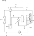
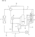
- FIG. 1 is a diagram illustrating a configuration of an air conditioner according to a first embodiment of the present invention.
- an air conditioner may include a compressor 1, an outdoor heat exchanger 2, an expansion device 3, and an indoor heat exchanger 4.
- the compressor 1, the outdoor heat exchanger 2, the expansion device 3, and the indoor heat exchanger 4 may be connected to each other via refrigerant pipes.
- the compressor 1, the outdoor heat exchanger 2, and the expansion device 3 may form an outdoor unit.
- the outdoor unit may include an outdoor blower (not shown) for blowing air toward the outdoor heat exchanger 2. Outdoor air may be introduced into the outdoor unit upon rotation of the outdoor blower, heat-exchanged with the outdoor heat exchanger 2, and then discharged to an outside.
- the indoor heat exchanger 4 may form an indoor unit.
- the indoor unit may further include an indoor blower (not shown) for blowing air toward the indoor heat exchanger 4.
- Indoor air may be introduced into the indoor unit upon rotation of the indoor blower, heat-exchanged with the indoor heat exchanger 4, and then discharged to an inside.
- the outdoor heat exchanger 2 may function as a condenser and the indoor heat exchanger 4 may function as an evaporator.
- a refrigerant may circulate by passing through the compressor 1, the outdoor heat exchanger 2, the expansion device 3, the indoor heat exchanger 4, and then the compressor 1, sequentially.
- the outdoor heat exchanger 2 may function as an evaporator and the indoor heat exchanger 4 may function as a condenser.
- a refrigerant may circulate by passing through the compressor 1, the indoor heat exchanger 4, the expansion device 3, the outdoor heat exchanger 2, and then the compressor 1, sequentially.
- the compressor 1 may compress a refrigerant.
- the condenser may condense a refrigerant having passed through the compressor 1.
- the expansion device 3 may expand a refrigerant having passed through the condenser.
- the evaporator may evaporate a refrigerant having passed through the expansion device 3.
- the air conditioner may be implemented as an air conditioner capable of performing both a cooing operation and a heating operation. However, the air conditioner may be implemented as an air conditioner capable of performing only a heating operation.
- the air conditioner will be described as being implemented as an air conditioner capable of performing both a cooing operation and a heating operation.
- the air conditioner according to an embodiment of the present invention may further include a cooling and heating switch valve 7.
- the cooling and heating switch valve 7 may be included in the outdoor unit.
- the cooling and heating switch valve 7 may switch a flow of refrigerants discharged from the compressor 1 to one of the outdoor heat exchanger 2 and the indoor heat exchanger 4.
- a compressor suction channel 81, 8, 85 may connect a heating-operation outlet of the outdoor heat exchanger 2 and an inlet of the compressor 1.
- the compressor suction channel 81, 8, 85 may include an accumulator 8 for separating a refrigerant into a liquid refrigerant component and a vapor refrigerant component, a first refrigerant pipe 81 connecting the heating-operation outlet of the outdoor heat exchanger 2 and the inlet of the compressor 1, and a compressor inflow pipe 85 connecting an outlet of the accumulator 8 and an inlet of the compressor 1.
- a liquid refrigerant component and a vapor refrigerant component may flow from the outdoor heat exchanger 2 to the accumulator 8 through the first refrigerant pipe 81. Having flown into the accumulator 8, the refrigerant may be separated into a liquid refrigerant component and a vapor refrigerant component.
- the liquid refrigerant component separated in the accumulator 8 may be received in a lower side of the accumulator, and the vapor refrigerant component separated in the accumulator 8 may be positioned above the separated liquid refrigerant.
- the vapor refrigerant component separated in the accumulator 8 may flow to the compressor 1 through the compressor inflow pipe 85, and the liquid refrigerant component separated in the accumulator 8 may remain intact in the accumulator 8.
- a second refrigerant pipe 82 may connect a heating-operation outlet of the indoor heat exchanger 4 and a heating-operation inlet of the expansion device 3.
- a third refrigerant pipe 83 may connect a heating-operation outlet of the expansion device 3 and a heating-operation inlet of the outdoor heat exchanger 2.
- a fourth refrigerant pipe 84 may connect an outlet of the compressor 1 and a heating-operation inlet of the indoor heat exchanger 4.
- the cooling and heating switch valve 7 may be installed in the first refrigerant pipe 81 and the fourth refrigerant pipe 84.
- a refrigerant compressed in the compressor 1 moves to the cooling and heating switch valve through a front portion of the fourth refrigerant pipe 84.
- the refrigerant having moved to the cooling and heating switch valve 7 moves to the indoor heat exchanger 4 through a rear portion of the fourth refrigerant pipe 84.
- the refrigerant pipe having moved to the indoor heat exchanger 4 moves to the expansion device 3 through the second refrigerant pipe 82.
- the refrigerant having moved to the expansion device 3 moves to the outdoor heat exchanger 2 through the third refrigerant pipe 83.
- the refrigerant having moved to the outdoor heat exchanger 2 moves to the cooling and heating switch valve 7 through a front portion of the first refrigerant pipe 81.
- the refrigerant having moved to the cooling and heating switch valve 7 moves to the accumulator 8 through a rear portion of the first refrigerant pipe 81.
- the refrigerant having moved to the accumulator 8 moves to the compressor 1 through the compressor inflow pipe 85. In the heating operation of the air conditioner, the refrigerant repeatedly flow in this manner.
- a refrigerant compressed in the compressor 1 moves to the cooling and heating switch valve 7 through a front portion of the fourth refrigerant pipe 84.
- the refrigerant having moved to the cooling and heating switch valve 7 moves to the outdoor heat exchanger 2 through a front portion of the first refrigerant pipe 81.
- the refrigerant having moved to the outdoor heat exchanger 2 moves to the expansion device 3 through the second refrigerant pipe 82.
- the refrigerant having moved to the expansion device 3 moves to the indoor heat exchanger 4 through the second refrigerant pipe 82.
- the refrigerant having moved to the indoor heat exchanger 4 moves to the cooling and heating switch valve through a rear portion of the fourth refrigerant pipe 84.
- the refrigerant having moved to the cooling and heating switch valve 7 moves to the accumulator 8 through a rear portion of the first refrigerant pipe 81.
- the refrigerant having moved to the accumulator 8 moves to the compressor 1 through the compressor inflow pipe 85. In a cooling operation of the air conditioner, the refrigerant repeatedly flow in this manner.
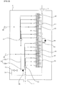
- FIG. 2 is a diagram illustrating a refrigerant flow in an outdoor heat exchanger, shown in FIG. 1 , in a heating operation of the air conditioner according to the first embodiment of the present invention.
- FIG. 3 is a diagram illustrating a refrigerant flow in an outdoor heat exchanger, shown in FIG. 1 , in a cooling operation of the air conditioner according to the first embodiment of the present invention.
- the outdoor heat exchanger 2 may include a plurality of unit channels 20 and 30 into which a refrigerant channel is partitioned.
- a refrigerant channel is partitioned into two unit channels.
- aspects of the present invention are not limited thereto, and the refrigerant channel of the outdoor heat exchanger 2 may be partitioned into three or more unit channels.
- the refrigerant channel of the outdoor heat exchanger 2 is partitioned into a first unit channel 20 and a second unit channel 30.
- first unit channel 20 and one side of the second unit channel 30 are connected in parallel to each other by a first parallel connection channel 50.
- the other side of the first unit channel 20 and the other side of the second unit channel 30 are connected in parallel to each other by a second parallel connection channel 60.
- first distributor 51 corresponding to the first unit channel 20 and a second distributor 52 corresponding to the second unit channel 30 are installed.
- the first distributor 51 plays a role of distributing introduced refrigerants into the first unit channel 20 in a heating operation
- the second distributor 52 plays a role of distributing introduced refrigerants into the second unit channel 30 in the heating operation.
- the first parallel connection channel 50 includes a first distributor connecting channel 50a connecting an outlet of the outdoor heat exchanger 2 and the first distributor 51, and a second distributor connecting channel 50b connecting the outlet of the outdoor heat exchanger 2 and the second distributor 52.
- a first header 61 is installed at a portion corresponding to the first unit channel 20 and a second header 62 is installed at a portion corresponding to the second unit channel 30.
- the distributors 51 and 52 are installed at a side through which a liquid refrigerant component is introduced, and it is advantageous that the headers 61 and 62 are installed at a side through which a vapor refrigerant component is introduced. Accordingly, it is preferable that the distributors 51 and 52 are positioned on the side of a first port 11 through which a two-phase refrigerant are introduced in a heating operation, and that the headers 61 and 62 are positioned on the side of a second port 12 through which a vapor refrigerant component is introduced in a cooling operation.
- the first port 11 serves an inlet through which a refrigerant is introduced, and the second port 12 serves as an outlet through which a refrigerant is discharged.
- the first port 11 serves as an outlet through which a refrigerant is discharged, and the second port 12 serves as an inlet through a refrigerant is introduced.
- the outdoor heat exchanger 2 further includes a channel switching device for switching a channel so that the first parallel connection channel 50, the second parallel connection channel 60, and a serial connection channel 70, described below, may be selectively used.
- the channel switching device may include an opening and closing valve installed in at least one of the first parallel connection channel 50, the second parallel connection channel 60, and the serial connection channel 70 to open and close a channel.
- the channel switching device may include a check valve for allowing a refrigerant to flow only in one direction.
- the channel switching device includes a parallel connection valve 64, a serial connection valve 72, and a backward preventing valve 54, which are described below.
- the parallel connection valve 64 for closing the second parallel connection channel 60 in a cooling operation and opening the second parallel connection channel 60 in a heating operation is installed.
- the parallel connection valve 64 allows the first header 61 and the second header 62 to communicate with each other, so that the second parallel connection channel 60 is opened.
- the parallel connection valve 64 prevents a refrigerant having passed through the first header 61 from being introduced into the second header 62, so that the second parallel connection channel 60 is closed.
- a check valve for allowing a refrigerant to flow only in one direction from the second header 62 toward the first header 61 is used as the parallel connection valve 64.
- the first header 61 and the second header 62 may be installed in the first parallel connection channel 50, and the first distributor 51 and the second distributor 52 may be installed in the second parallel connection channel 60. However, it is more preferable that a distributor rather than a header is installed on the side through which a liquid refrigerant component passes.
- the outdoor heat exchanger 2 may further include the serial connection channel 70 for connecting the first unit channel 20 and the second unit channel 30 in serial in a cooling operation.
- the serial connection channel 70 allows a refrigerant having passed through the first unit channel 20 to be bypassed toward the second unit channel 30. That is, the serial connection channel 70 is bypassed from the first distributor channel 50a and thereby connected to the second header 62.
- the serial connection valve 72 for opening the serial connection channel 70 in the cooling operation and closing the serial connection channel 70 in the heating operation is installed.
- a backflow preventing valve 54 for preventing a refrigerant having passed through the first unit channel 20 from backflowing toward the second unit channel 30 in the cooling operation is installed in the first parallel connection channel 50. That is, the backflow preventing valve 54 may be installed between the first distributor channel 50a and the second distributor channel 50b, and a check valve may be used as the backflow preventing valve 54.
- the outdoor heat exchanger 2 may further include a separating device installed at each of the plurality of unit channels 20 and 30 to separate a refrigerant into a liquid refrigerant component and a vapor refrigerant component in each of the plurality of unit channels 20 and 30 in the heating operation.
- the separating device 90 may separate a refrigerant into a liquid refrigerant component and a vapor refrigerant component at a middle point in a corresponding unit channel of the plurality of unit channels 20 and 30.
- the air conditioner may further include a bypass pipe 86 connecting the separating device 90 and the compressor suction channel 81, 8, 85 to bypass the vapor refrigerant component separated from the separating device 90 toward the compressor suction channel 81, 8, 85 in the heating operation.
- the bypass pipe 86 may connect the separating device and the compressor inflow pipe 85.
- One end of the bypass pipe 86 may be branched into two parts, and the two parts branched from one end of the bypass pipe 86 may be connected to the plurality of unit channels 20 and 30. That is, one of the two parts branched from one end of the bypass pipe 86 may be connected to a separating device 90 provided in the first unit channel 20, and the other one of the two parts may be connected to the separating device 90 provided in a separating device 90 provided in the second unit channel 30.
- the other end of the bypass pipe 86 may be connected to a portion adjacent to the inlet of the compressor 1 in the compressor inflow pipe 85.
- a refrigerant introduced into the bypass pipe 86 from the plurality of unit channels 20 and 30 in a heating operation may be introduced into the compressor 1 through the compressor inflow pipe 85.
- a flow rate control valve 87 for opening the bypass pipe 86 in the heating operation and closing the bypass pipe 86 in the cooling operation may be installed.
- the flow rate control valve 87 may be an opening/closing vale and may control an amount of refrigerants flowing after being introduced from the plurality of unit channels 20 and 30 into the bypass pipe 86.
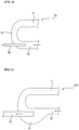
- FIG. 4 is a diagram illustrating a first embodiment of a separating device shown in FIG. 1 .
- the separating device 90 may be a return pipe 90 connecting two adjacent refrigerant pipes among a plurality of refrigerant pipes respectively provided in the plurality of unit channels 20.
- the return pipe 90 may be provided in plural in each of the plurality of unit channels 20 and 30.
- One end of the bypass pipe 86 may be connected to a return pipe 90 positioned in the middle of a plurality of return pipe 90. That is, one of two parts branched from one end of the bypass pipe 86 may be connected to a return pipe 90 positioned in the middle of a plurality of return pipes 90 provided in the first unit channel 20, and the other one of the two parts branched from one end of the bypass pipe 86 may be connected to a return pipe 90 positioned in the middle of a plurality of return pipes 90 provided in the second unit channel 30.
- a return pipe 90 may be formed in a U shape. That is, the return pipe 90 may include a pair of straight parts 91 and 92 arranged in parallel to each other, an arc-shaped bending potion 93 connecting one ends of the straight parts 91 and 92 to each other.
- the pair of straight parts 91 and 92 may include a first straight part 91 and a second straight part 92.
- the bypass pipe 86 may be connected to the bending part positioned in a longitudinal direction of any one of the straight parts 91 and 92. That is, the two parts branched from one end of the bypass pipe 86 may be connected to the bending part 93 positioned in the longitudinal direction of any one of the straight parts 91 and 92. The two parts branched from one end of the bypass pipe 86, branched into two parts may be connected to the bending part 93 positioned in the longitudinal direction of the second straight part 92.
- a diameter of the bypass pipe 86 may be formed smaller than a diameter of the return pipe 90.
- a vapor refrigerant component in a liquid refrigerant component and the vapor refrigerant component separated in the return pipe 90 may flow into the bypass pipe 86 having a diameter smaller than the diameter of the return pipe 90.
- FIG. 5 is a diagram illustrating a second embodiment of a separating device shown in FIG. 1 .
- the same elements as in the first embodiment of the separating device shown in FIG. 4 are indicated by the same reference numerals, and a detailed description of the same elements will be omitted only a difference from the separating device shown in FIG. 4 will be described.
- a return pipe 900 may include a pair of straight parts 91 and 92, and an arch-shaped bending part 93 connecting one ends of the straight parts 91 and 92.
- an expansion part 94 having an inner space larger than the remaining space may be formed.
- an expansion part 94 having an inner space larger than the remaining space of the second straight part 92 may be formed.
- the liquid refrigerant component and the vapor refrigerant component separated in the return pipe 900 the liquid refrigerant component may be stored in the expansion part 94, and the vapor refrigerant component may move to the bypass pipe 86.
- FIG. 6 is a diagram illustrating a third embodiment of a separating device shown in FIG. 1 .
- the same elements as in the first embodiment of the separating device shown in FIG. 4 are indicated by the same reference numerals, and a detailed description of the same elements will be omitted only a difference from the separating device shown in FIG. 4 will be described.
- a return pipe 9000 may include a straight parts 91 and 92 arranged in parallel to each other, and a spring-shaped bending part 95 connecting one end of the straight parts 91 and 92.
- the bypass pipe 86 may be connected to the bending part 95 positioned in a longitudinal direction of any one of the straight parts 91 and 92.
- a refrigerant introduced into the bending part 95 may be separated into a liquid refrigerant component and a vapor refrigerant component while rotating about a virtual straight line vertical to the longitudinal direction of any one of the straight parts 91 and 92.
- Such a separating device may have the same meaning of the return pipes 90, 900, and 9000.
- the separating device will be described with reference numeral 90.
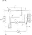
- FIG. 7 is a diagram illustrating a configuration of an air conditioner according to a second embodiment of the present invention.
- the same elements identical to those in the first embodiment of the air conditioner shown in FIG. 1 are indicated by the same reference numerals, and a detailed description of the same elements will be omitted and only a difference from the first embodiment of the air conditioner will be described.
- a bypass pipe 86 may connect a separating device 90 and a first refrigerant pipe 81.
- the bypass refrigerant pipe 86 may be connected to a portion adjacent to an inlet of the accumulator 8 in the first refrigerant pipe 81.
- a refrigerant introduced into the bypass pipe 86 from the plurality of unit channels 20 and 30 may be introduced into the accumulator 8 through the first refrigerant pipe 81 and then separated into a liquid refrigerant component and a vapor refrigerant component.
- the vapor refrigerant component separated in the accumulator 8 may be introduced into the compressor 1 through the compressor inflow pipe 85, and the liquid refrigerant component separated in the accumulator 8 may remain intact in the accumulator 8.
- FIG. 8 is a diagram illustrating a configuration of an air conditioner according to a third embodiment of the present invention.
- the same elements identical to those in the first embodiment of the air conditioner shown in FIG. 1 are indicated by the same reference numerals, and a detailed description of the same elements will be omitted and only a difference from the first embodiment of the air conditioner will be described.
- bypass pipe 86 may connect the separating means 90 and the accumulator 8.
- a refrigerant introduced into the bypass pipe 86 from the plurality of unit channels 20 and 30 may be introduced into the accumulator 8 and then separated into a liquid refrigerant component and a vapor refrigerant component.
- the vapor refrigerant component separated in the accumulator 8 may be introduced into the compressor 1 through the compressor inflow pipe 85, and the liquid refrigerant component separated in the accumulator 8 may remain intact in the accumulator 8.
- FIG. 9 is a diagram illustrating a configuration of an air conditioner according to a fourth embodiment of the present invention.
- the same elements identical to those in the first embodiment of the air conditioner shown in FIG. 1 are indicated by the same reference numerals, and a detailed description of the same elements will be omitted and only a difference from the first embodiment of the air conditioner will be described.
- a supercooling device 9 is further installed in the second refrigerant pipe 82.
- the bypass pipe 86 may pass through the supercooling device 9.
- a refrigerant having passed through the indoor heat exchanger 4 may be introduced into the supercooling device 9 through a front portion of the second refrigerant pipe 82.
- the refrigerant introduced into the supercooling device 9 may become supercooled by performing heat exchange with a refrigerant flowing in the bypass pipe 86 and be then introduced into the expansion device 3 through a rear portion of the second refrigerant pipe 82.
- FIG. 10 is a diagram illustrating a configuration of an air conditioner according to a fifth embodiment of the present invention.
- the same elements identical to those in the third embodiment of the air conditioner shown in FIG. 8 are indicated by the same reference numerals, and a detailed description of the same elements will be omitted and only a difference from the first embodiment of the air conditioner will be described.
- a supercooling device 9 is installed in the second refrigerant pipe 82.
- the air conditioner according to the fifth embodiment further includes an auxiliary bypass pipe 88 connecting the accumulator 8 and the compressor inflow pipe 85 and passing through the supercooling device 9.
- the flow rate control valve 87 may be installed in the auxiliary bypass pipe 88 rather than the bypass pipe 86.
- a refrigerant introduced into the bypass pipe 86 from the plurality of unit channels 20 and 30 may be introduced into the accumulator 8 and then separated into a liquid refrigerant component and a vapor refrigerant component.
- the vapor refrigerant component separated in the accumulator 8 may be introduced into the compressor 1 through the compressor inflow pipe 85.
- the auxiliary bypass pipe 88 may allow the liquid refrigerant component separated in the accumulator 8 to pass through the supercooling device 9 and thereby turned into a vapor refrigerant component and bypassed to the compressor inflow pipe 85.
- the air conditioner according to embodiments of the present invention separates a refrigerant in each of the plurality of unit channels 20 and 30 of the outdoor heat exchanger 2 into a liquid refrigerant component and a vapor refrigerant component in a heating operation in a cold region and bypasses the separated refrigerant to the compressor suction channels 81, 8, 85, it is possible to reduce not just a refrigerant pressure loss in the outdoor heat exchanger 2 but also a refrigerant flow rate in the outdoor heat exchanger 2 to additionally reduce a pressure loss of a refrigerant flowing in a rear portion of the outdoor heat exchanger 2, thereby improving heating performance in the cold region.
- the air conditioner separates a refrigerant in each of the plurality of unit channels of the outdoor heat exchanger into a liquid refrigerant component and a vapor refrigerant component in a heating operation in a cold region and bypasses the separated refrigerant to the compressor suction channels, it is possible to reduce not just a refrigerant pressure loss in the outdoor heat exchanger but also a refrigerant flow rate in the outdoor heat exchanger to additionally reduce a pressure loss of a refrigerant flowing in a rear portion of the outdoor heat exchanger, thereby improving heating performance in the cold region.
Landscapes
- Engineering & Computer Science (AREA)
- Mechanical Engineering (AREA)
- General Engineering & Computer Science (AREA)
- Physics & Mathematics (AREA)
- Chemical & Material Sciences (AREA)
- Thermal Sciences (AREA)
- Combustion & Propulsion (AREA)
- Analytical Chemistry (AREA)
- Power Engineering (AREA)
- Fluid Mechanics (AREA)
- Compression-Type Refrigeration Machines With Reversible Cycles (AREA)
Applications Claiming Priority (1)
| Application Number | Priority Date | Filing Date | Title |
|---|---|---|---|
| KR1020180136693A KR102192386B1 (ko) | 2018-11-08 | 2018-11-08 | 공기조화기 |
Publications (2)
| Publication Number | Publication Date |
|---|---|
| EP3650764A1 true EP3650764A1 (fr) | 2020-05-13 |
| EP3650764B1 EP3650764B1 (fr) | 2021-06-02 |
Family
ID=68501418
Family Applications (1)
| Application Number | Title | Priority Date | Filing Date |
|---|---|---|---|
| EP19207975.4A Active EP3650764B1 (fr) | 2018-11-08 | 2019-11-08 | Climatiseur |
Country Status (3)
| Country | Link |
|---|---|
| US (1) | US11441793B2 (fr) |
| EP (1) | EP3650764B1 (fr) |
| KR (1) | KR102192386B1 (fr) |
Cited By (4)
| Publication number | Priority date | Publication date | Assignee | Title |
|---|---|---|---|---|
| CN112432340A (zh) * | 2020-11-26 | 2021-03-02 | 珠海格力电器股份有限公司 | 空调的控制方法、控制装置、处理器和空调系统 |
| CN113573543A (zh) * | 2021-06-10 | 2021-10-29 | 华为技术有限公司 | 分布式复合制冷系统和数据中心 |
| CN114963345A (zh) * | 2022-06-07 | 2022-08-30 | 深圳市英威腾网能技术有限公司 | 一种多系统空调室外机 |
| CN115507573A (zh) * | 2021-06-22 | 2022-12-23 | Lg电子株式会社 | 包括制冷剂循环的设备 |
Families Citing this family (7)
| Publication number | Priority date | Publication date | Assignee | Title |
|---|---|---|---|---|
| US11105544B2 (en) * | 2016-11-07 | 2021-08-31 | Trane International Inc. | Variable orifice for a chiller |
| US11221151B2 (en) * | 2019-01-15 | 2022-01-11 | Johnson Controls Technology Company | Hot gas reheat systems and methods |
| KR102822341B1 (ko) | 2019-10-23 | 2025-06-19 | 엘지전자 주식회사 | 기액 분리기 및 이를 포함하는 공기 조화기 |
| KR20220028700A (ko) * | 2020-08-31 | 2022-03-08 | 엘지전자 주식회사 | 공기조화기 |
| CN112944453B (zh) * | 2021-02-26 | 2023-03-31 | 青岛海尔空调电子有限公司 | 三管式多联机空调机组的控制方法 |
| CN117006742B (zh) * | 2022-04-29 | 2025-10-31 | 广东美的制冷设备有限公司 | 换热器、换热器的流路控制方法、存储介质及家用电器 |
| KR20250016536A (ko) * | 2023-07-19 | 2025-02-04 | 엘지전자 주식회사 | 열공급장치 |
Citations (4)
| Publication number | Priority date | Publication date | Assignee | Title |
|---|---|---|---|---|
| EP1400765A2 (fr) * | 2002-09-17 | 2004-03-24 | Kabushiki Kaisha Kobe Seiko Sho | Appareil frigorifique à compresseur à vis |
| WO2010117973A2 (fr) * | 2009-04-09 | 2010-10-14 | Carrier Corporation | Système de compression de vapeur de frigorigène avec dérivation de gaz chaud |
| EP2975336A1 (fr) * | 2013-03-12 | 2016-01-20 | Mitsubishi Electric Corporation | Climatiseur |
| US20160054077A1 (en) * | 2014-08-19 | 2016-02-25 | Carrier Corporation | Multipass microchannel heat exchanger |
Family Cites Families (6)
| Publication number | Priority date | Publication date | Assignee | Title |
|---|---|---|---|---|
| JPH09152216A (ja) * | 1995-12-01 | 1997-06-10 | Toshiba Corp | 空気調和機 |
| JP5452367B2 (ja) | 2010-05-26 | 2014-03-26 | 三菱電機株式会社 | 気液分離器および冷凍サイクル装置 |
| KR101233209B1 (ko) * | 2010-11-18 | 2013-02-15 | 엘지전자 주식회사 | 히트 펌프 |
| KR101894440B1 (ko) * | 2012-12-26 | 2018-09-03 | 한온시스템 주식회사 | 차량용 히트펌프 시스템의 실외 열교환기 |
| JP2015010816A (ja) | 2013-07-02 | 2015-01-19 | 三菱電機株式会社 | 冷媒回路および空気調和装置 |
| KR102198311B1 (ko) * | 2017-03-13 | 2021-01-05 | 엘지전자 주식회사 | 공기조화시스템 |
-
2018
- 2018-11-08 KR KR1020180136693A patent/KR102192386B1/ko active Active
-
2019
- 2019-11-08 EP EP19207975.4A patent/EP3650764B1/fr active Active
- 2019-11-08 US US16/678,510 patent/US11441793B2/en active Active
Patent Citations (4)
| Publication number | Priority date | Publication date | Assignee | Title |
|---|---|---|---|---|
| EP1400765A2 (fr) * | 2002-09-17 | 2004-03-24 | Kabushiki Kaisha Kobe Seiko Sho | Appareil frigorifique à compresseur à vis |
| WO2010117973A2 (fr) * | 2009-04-09 | 2010-10-14 | Carrier Corporation | Système de compression de vapeur de frigorigène avec dérivation de gaz chaud |
| EP2975336A1 (fr) * | 2013-03-12 | 2016-01-20 | Mitsubishi Electric Corporation | Climatiseur |
| US20160054077A1 (en) * | 2014-08-19 | 2016-02-25 | Carrier Corporation | Multipass microchannel heat exchanger |
Cited By (10)
| Publication number | Priority date | Publication date | Assignee | Title |
|---|---|---|---|---|
| CN112432340A (zh) * | 2020-11-26 | 2021-03-02 | 珠海格力电器股份有限公司 | 空调的控制方法、控制装置、处理器和空调系统 |
| CN112432340B (zh) * | 2020-11-26 | 2021-11-26 | 珠海格力电器股份有限公司 | 空调的控制方法、控制装置、处理器和空调系统 |
| CN113573543A (zh) * | 2021-06-10 | 2021-10-29 | 华为技术有限公司 | 分布式复合制冷系统和数据中心 |
| CN113573543B (zh) * | 2021-06-10 | 2023-09-29 | 华为数字能源技术有限公司 | 分布式复合制冷系统和数据中心 |
| CN115507573A (zh) * | 2021-06-22 | 2022-12-23 | Lg电子株式会社 | 包括制冷剂循环的设备 |
| EP4109013A1 (fr) * | 2021-06-22 | 2022-12-28 | LG Electronics Inc. | Dispositif ayant un cycle de réfrigérant |
| CN115507573B (zh) * | 2021-06-22 | 2023-12-15 | Lg电子株式会社 | 包括制冷剂循环的设备 |
| US11988424B2 (en) | 2021-06-22 | 2024-05-21 | Lg Electronics Inc. | Device having refrigerant cycle |
| CN114963345A (zh) * | 2022-06-07 | 2022-08-30 | 深圳市英威腾网能技术有限公司 | 一种多系统空调室外机 |
| CN114963345B (zh) * | 2022-06-07 | 2023-11-28 | 深圳市英威腾网能技术有限公司 | 一种多系统空调室外机 |
Also Published As
| Publication number | Publication date |
|---|---|
| KR102192386B1 (ko) | 2020-12-17 |
| US11441793B2 (en) | 2022-09-13 |
| EP3650764B1 (fr) | 2021-06-02 |
| US20200149751A1 (en) | 2020-05-14 |
| KR20200053269A (ko) | 2020-05-18 |
Similar Documents
| Publication | Publication Date | Title |
|---|---|---|
| EP3650764B1 (fr) | Climatiseur | |
| CN109328287B (zh) | 制冷循环装置 | |
| US11466908B2 (en) | Outdoor heat exchanger and air conditioner having the same | |
| EP2623873B1 (fr) | Échangeur de chaleur extérieur et climatiseur comprenant celui-ci | |
| US8424333B2 (en) | Air conditioner | |
| CN106885361A (zh) | 室外换热器以及包含该室外换热器的空调装置 | |
| EP2354723A2 (fr) | Système réfrigérant | |
| US11680740B2 (en) | Gas-liquid separator and air conditioner having the same | |
| KR20180104416A (ko) | 공기조화시스템 | |
| EP3686516A1 (fr) | Climatiseur | |
| KR20180039862A (ko) | 히트펌프식 급탕장치 및 그 제어방법 | |
| EP3892928A1 (fr) | Climatiseur | |
| US9267716B2 (en) | Heat exchanger and an air conditioning system having the same | |
| CN113251473B (zh) | 空调装置 | |
| KR20190088693A (ko) | 멀티형 공기조화기 | |
| CN107499089A (zh) | 一种电动汽车热泵空调系统及其工作方法 | |
| KR102337394B1 (ko) | 공기조화기 | |
| KR101120371B1 (ko) | 냉매시스템 | |
| KR102718100B1 (ko) | 차량용 냉난방 시스템 | |
| CN206019070U (zh) | 换热器、空调室外机、热泵系统及空调器 | |
| EP3578898B1 (fr) | Unité extérieure pour climatiseur | |
| KR102436705B1 (ko) | 공기조화기 | |
| KR20180123270A (ko) | 공기조화기 | |
| JP2000234818A (ja) | 空調装置の冷媒過冷却機構 | |
| CN107975959A (zh) | 一种多联机空调系统及控制方法 |
Legal Events
| Date | Code | Title | Description |
|---|---|---|---|
| PUAI | Public reference made under article 153(3) epc to a published international application that has entered the european phase |
Free format text: ORIGINAL CODE: 0009012 |
|
| STAA | Information on the status of an ep patent application or granted ep patent |
Free format text: STATUS: REQUEST FOR EXAMINATION WAS MADE |
|
| 17P | Request for examination filed |
Effective date: 20191208 |
|
| AK | Designated contracting states |
Kind code of ref document: A1 Designated state(s): AL AT BE BG CH CY CZ DE DK EE ES FI FR GB GR HR HU IE IS IT LI LT LU LV MC MK MT NL NO PL PT RO RS SE SI SK SM TR |
|
| RBV | Designated contracting states (corrected) |
Designated state(s): AL AT BE BG CH CY CZ DE DK EE ES FI FR GB GR HR HU IE IS IT LI LT LU LV MC MK MT NL NO PL PT RO RS SE SI SK SM TR |
|
| GRAP | Despatch of communication of intention to grant a patent |
Free format text: ORIGINAL CODE: EPIDOSNIGR1 |
|
| STAA | Information on the status of an ep patent application or granted ep patent |
Free format text: STATUS: GRANT OF PATENT IS INTENDED |
|
| RIC1 | Information provided on ipc code assigned before grant |
Ipc: F24F 11/30 20180101ALI20201222BHEP Ipc: F24F 1/16 20110101AFI20201222BHEP Ipc: F28F 9/02 20060101ALI20201222BHEP Ipc: F25B 13/00 20060101ALI20201222BHEP Ipc: F24F 140/12 20180101ALI20201222BHEP Ipc: F24F 13/30 20060101ALI20201222BHEP |
|
| INTG | Intention to grant announced |
Effective date: 20210122 |
|
| GRAS | Grant fee paid |
Free format text: ORIGINAL CODE: EPIDOSNIGR3 |
|
| GRAA | (expected) grant |
Free format text: ORIGINAL CODE: 0009210 |
|
| STAA | Information on the status of an ep patent application or granted ep patent |
Free format text: STATUS: THE PATENT HAS BEEN GRANTED |
|
| REG | Reference to a national code |
Ref country code: CH Ref legal event code: EP |
|
| AK | Designated contracting states |
Kind code of ref document: B1 Designated state(s): AL AT BE BG CH CY CZ DE DK EE ES FI FR GB GR HR HU IE IS IT LI LT LU LV MC MK MT NL NO PL PT RO RS SE SI SK SM TR |
|
| REG | Reference to a national code |
Ref country code: GB Ref legal event code: FG4D |
|
| REG | Reference to a national code |
Ref country code: AT Ref legal event code: REF Ref document number: 1398809 Country of ref document: AT Kind code of ref document: T Effective date: 20210615 |
|
| REG | Reference to a national code |
Ref country code: IE Ref legal event code: FG4D |
|
| REG | Reference to a national code |
Ref country code: DE Ref legal event code: R096 Ref document number: 602019005073 Country of ref document: DE |
|
| REG | Reference to a national code |
Ref country code: LT Ref legal event code: MG9D |
|
| PG25 | Lapsed in a contracting state [announced via postgrant information from national office to epo] |
Ref country code: LT Free format text: LAPSE BECAUSE OF FAILURE TO SUBMIT A TRANSLATION OF THE DESCRIPTION OR TO PAY THE FEE WITHIN THE PRESCRIBED TIME-LIMIT Effective date: 20210602 Ref country code: HR Free format text: LAPSE BECAUSE OF FAILURE TO SUBMIT A TRANSLATION OF THE DESCRIPTION OR TO PAY THE FEE WITHIN THE PRESCRIBED TIME-LIMIT Effective date: 20210602 Ref country code: FI Free format text: LAPSE BECAUSE OF FAILURE TO SUBMIT A TRANSLATION OF THE DESCRIPTION OR TO PAY THE FEE WITHIN THE PRESCRIBED TIME-LIMIT Effective date: 20210602 Ref country code: BG Free format text: LAPSE BECAUSE OF FAILURE TO SUBMIT A TRANSLATION OF THE DESCRIPTION OR TO PAY THE FEE WITHIN THE PRESCRIBED TIME-LIMIT Effective date: 20210902 |
|
| REG | Reference to a national code |
Ref country code: NL Ref legal event code: MP Effective date: 20210602 |
|
| REG | Reference to a national code |
Ref country code: AT Ref legal event code: MK05 Ref document number: 1398809 Country of ref document: AT Kind code of ref document: T Effective date: 20210602 |
|
| PG25 | Lapsed in a contracting state [announced via postgrant information from national office to epo] |
Ref country code: PL Free format text: LAPSE BECAUSE OF FAILURE TO SUBMIT A TRANSLATION OF THE DESCRIPTION OR TO PAY THE FEE WITHIN THE PRESCRIBED TIME-LIMIT Effective date: 20210602 Ref country code: LV Free format text: LAPSE BECAUSE OF FAILURE TO SUBMIT A TRANSLATION OF THE DESCRIPTION OR TO PAY THE FEE WITHIN THE PRESCRIBED TIME-LIMIT Effective date: 20210602 Ref country code: NO Free format text: LAPSE BECAUSE OF FAILURE TO SUBMIT A TRANSLATION OF THE DESCRIPTION OR TO PAY THE FEE WITHIN THE PRESCRIBED TIME-LIMIT Effective date: 20210902 Ref country code: RS Free format text: LAPSE BECAUSE OF FAILURE TO SUBMIT A TRANSLATION OF THE DESCRIPTION OR TO PAY THE FEE WITHIN THE PRESCRIBED TIME-LIMIT Effective date: 20210602 Ref country code: SE Free format text: LAPSE BECAUSE OF FAILURE TO SUBMIT A TRANSLATION OF THE DESCRIPTION OR TO PAY THE FEE WITHIN THE PRESCRIBED TIME-LIMIT Effective date: 20210602 |
|
| PG25 | Lapsed in a contracting state [announced via postgrant information from national office to epo] |
Ref country code: ES Free format text: LAPSE BECAUSE OF FAILURE TO SUBMIT A TRANSLATION OF THE DESCRIPTION OR TO PAY THE FEE WITHIN THE PRESCRIBED TIME-LIMIT Effective date: 20210602 Ref country code: EE Free format text: LAPSE BECAUSE OF FAILURE TO SUBMIT A TRANSLATION OF THE DESCRIPTION OR TO PAY THE FEE WITHIN THE PRESCRIBED TIME-LIMIT Effective date: 20210602 Ref country code: SK Free format text: LAPSE BECAUSE OF FAILURE TO SUBMIT A TRANSLATION OF THE DESCRIPTION OR TO PAY THE FEE WITHIN THE PRESCRIBED TIME-LIMIT Effective date: 20210602 Ref country code: CZ Free format text: LAPSE BECAUSE OF FAILURE TO SUBMIT A TRANSLATION OF THE DESCRIPTION OR TO PAY THE FEE WITHIN THE PRESCRIBED TIME-LIMIT Effective date: 20210602 Ref country code: AT Free format text: LAPSE BECAUSE OF FAILURE TO SUBMIT A TRANSLATION OF THE DESCRIPTION OR TO PAY THE FEE WITHIN THE PRESCRIBED TIME-LIMIT Effective date: 20210602 Ref country code: PT Free format text: LAPSE BECAUSE OF FAILURE TO SUBMIT A TRANSLATION OF THE DESCRIPTION OR TO PAY THE FEE WITHIN THE PRESCRIBED TIME-LIMIT Effective date: 20211004 Ref country code: NL Free format text: LAPSE BECAUSE OF FAILURE TO SUBMIT A TRANSLATION OF THE DESCRIPTION OR TO PAY THE FEE WITHIN THE PRESCRIBED TIME-LIMIT Effective date: 20210602 Ref country code: RO Free format text: LAPSE BECAUSE OF FAILURE TO SUBMIT A TRANSLATION OF THE DESCRIPTION OR TO PAY THE FEE WITHIN THE PRESCRIBED TIME-LIMIT Effective date: 20210602 Ref country code: SM Free format text: LAPSE BECAUSE OF FAILURE TO SUBMIT A TRANSLATION OF THE DESCRIPTION OR TO PAY THE FEE WITHIN THE PRESCRIBED TIME-LIMIT Effective date: 20210602 |
|
| REG | Reference to a national code |
Ref country code: DE Ref legal event code: R097 Ref document number: 602019005073 Country of ref document: DE |
|
| PLBE | No opposition filed within time limit |
Free format text: ORIGINAL CODE: 0009261 |
|
| STAA | Information on the status of an ep patent application or granted ep patent |
Free format text: STATUS: NO OPPOSITION FILED WITHIN TIME LIMIT |
|
| PG25 | Lapsed in a contracting state [announced via postgrant information from national office to epo] |
Ref country code: DK Free format text: LAPSE BECAUSE OF FAILURE TO SUBMIT A TRANSLATION OF THE DESCRIPTION OR TO PAY THE FEE WITHIN THE PRESCRIBED TIME-LIMIT Effective date: 20210602 |
|
| 26N | No opposition filed |
Effective date: 20220303 |
|
| PG25 | Lapsed in a contracting state [announced via postgrant information from national office to epo] |
Ref country code: AL Free format text: LAPSE BECAUSE OF FAILURE TO SUBMIT A TRANSLATION OF THE DESCRIPTION OR TO PAY THE FEE WITHIN THE PRESCRIBED TIME-LIMIT Effective date: 20210602 |
|
| PG25 | Lapsed in a contracting state [announced via postgrant information from national office to epo] |
Ref country code: MC Free format text: LAPSE BECAUSE OF FAILURE TO SUBMIT A TRANSLATION OF THE DESCRIPTION OR TO PAY THE FEE WITHIN THE PRESCRIBED TIME-LIMIT Effective date: 20210602 |
|
| PG25 | Lapsed in a contracting state [announced via postgrant information from national office to epo] |
Ref country code: LU Free format text: LAPSE BECAUSE OF NON-PAYMENT OF DUE FEES Effective date: 20211108 Ref country code: BE Free format text: LAPSE BECAUSE OF NON-PAYMENT OF DUE FEES Effective date: 20211130 |
|
| REG | Reference to a national code |
Ref country code: BE Ref legal event code: MM Effective date: 20211130 |
|
| PG25 | Lapsed in a contracting state [announced via postgrant information from national office to epo] |
Ref country code: IE Free format text: LAPSE BECAUSE OF NON-PAYMENT OF DUE FEES Effective date: 20211108 |
|
| PG25 | Lapsed in a contracting state [announced via postgrant information from national office to epo] |
Ref country code: FR Free format text: LAPSE BECAUSE OF NON-PAYMENT OF DUE FEES Effective date: 20211130 |
|
| PG25 | Lapsed in a contracting state [announced via postgrant information from national office to epo] |
Ref country code: CY Free format text: LAPSE BECAUSE OF FAILURE TO SUBMIT A TRANSLATION OF THE DESCRIPTION OR TO PAY THE FEE WITHIN THE PRESCRIBED TIME-LIMIT Effective date: 20210602 |
|
| REG | Reference to a national code |
Ref country code: CH Ref legal event code: PL |
|
| PG25 | Lapsed in a contracting state [announced via postgrant information from national office to epo] |
Ref country code: LI Free format text: LAPSE BECAUSE OF NON-PAYMENT OF DUE FEES Effective date: 20221130 Ref country code: HU Free format text: LAPSE BECAUSE OF FAILURE TO SUBMIT A TRANSLATION OF THE DESCRIPTION OR TO PAY THE FEE WITHIN THE PRESCRIBED TIME-LIMIT; INVALID AB INITIO Effective date: 20191108 Ref country code: GR Free format text: LAPSE BECAUSE OF FAILURE TO SUBMIT A TRANSLATION OF THE DESCRIPTION OR TO PAY THE FEE WITHIN THE PRESCRIBED TIME-LIMIT Effective date: 20210602 Ref country code: CH Free format text: LAPSE BECAUSE OF NON-PAYMENT OF DUE FEES Effective date: 20221130 |
|
| PG25 | Lapsed in a contracting state [announced via postgrant information from national office to epo] |
Ref country code: MK Free format text: LAPSE BECAUSE OF FAILURE TO SUBMIT A TRANSLATION OF THE DESCRIPTION OR TO PAY THE FEE WITHIN THE PRESCRIBED TIME-LIMIT Effective date: 20210602 |
|
| GBPC | Gb: european patent ceased through non-payment of renewal fee |
Effective date: 20231108 |
|
| PG25 | Lapsed in a contracting state [announced via postgrant information from national office to epo] |
Ref country code: MT Free format text: LAPSE BECAUSE OF FAILURE TO SUBMIT A TRANSLATION OF THE DESCRIPTION OR TO PAY THE FEE WITHIN THE PRESCRIBED TIME-LIMIT Effective date: 20210602 |
|
| PG25 | Lapsed in a contracting state [announced via postgrant information from national office to epo] |
Ref country code: GB Free format text: LAPSE BECAUSE OF NON-PAYMENT OF DUE FEES Effective date: 20231108 |
|
| PG25 | Lapsed in a contracting state [announced via postgrant information from national office to epo] |
Ref country code: GB Free format text: LAPSE BECAUSE OF NON-PAYMENT OF DUE FEES Effective date: 20231108 |
|
| PG25 | Lapsed in a contracting state [announced via postgrant information from national office to epo] |
Ref country code: TR Free format text: LAPSE BECAUSE OF FAILURE TO SUBMIT A TRANSLATION OF THE DESCRIPTION OR TO PAY THE FEE WITHIN THE PRESCRIBED TIME-LIMIT Effective date: 20210602 |
|
| PGFP | Annual fee paid to national office [announced via postgrant information from national office to epo] |
Ref country code: DE Payment date: 20251002 Year of fee payment: 7 |
|
| PGFP | Annual fee paid to national office [announced via postgrant information from national office to epo] |
Ref country code: IT Payment date: 20251002 Year of fee payment: 7 |