EP3650816B1 - System und verfahren für magnetischen positionssensor - Google Patents
System und verfahren für magnetischen positionssensor Download PDFInfo
- Publication number
- EP3650816B1 EP3650816B1 EP19207358.3A EP19207358A EP3650816B1 EP 3650816 B1 EP3650816 B1 EP 3650816B1 EP 19207358 A EP19207358 A EP 19207358A EP 3650816 B1 EP3650816 B1 EP 3650816B1
- Authority
- EP
- European Patent Office
- Prior art keywords
- magnetic field
- magnetic
- sensor device
- determining
- sqr
- Prior art date
- Legal status (The legal status is an assumption and is not a legal conclusion. Google has not performed a legal analysis and makes no representation as to the accuracy of the status listed.)
- Active
Links
Images




Classifications
-
- G—PHYSICS
- G01—MEASURING; TESTING
- G01B—MEASURING LENGTH, THICKNESS OR SIMILAR LINEAR DIMENSIONS; MEASURING ANGLES; MEASURING AREAS; MEASURING IRREGULARITIES OF SURFACES OR CONTOURS
- G01B7/00—Measuring arrangements characterised by the use of electric or magnetic techniques
- G01B7/003—Measuring arrangements characterised by the use of electric or magnetic techniques for measuring position, not involving coordinate determination
-
- G—PHYSICS
- G01—MEASURING; TESTING
- G01D—MEASURING NOT SPECIALLY ADAPTED FOR A SPECIFIC VARIABLE; ARRANGEMENTS FOR MEASURING TWO OR MORE VARIABLES NOT COVERED IN A SINGLE OTHER SUBCLASS; TARIFF METERING APPARATUS; MEASURING OR TESTING NOT OTHERWISE PROVIDED FOR
- G01D5/00—Mechanical means for transferring the output of a sensing member; Means for converting the output of a sensing member to another variable where the form or nature of the sensing member does not constrain the means for converting; Transducers not specially adapted for a specific variable
- G01D5/12—Mechanical means for transferring the output of a sensing member; Means for converting the output of a sensing member to another variable where the form or nature of the sensing member does not constrain the means for converting; Transducers not specially adapted for a specific variable using electric or magnetic means
- G01D5/14—Mechanical means for transferring the output of a sensing member; Means for converting the output of a sensing member to another variable where the form or nature of the sensing member does not constrain the means for converting; Transducers not specially adapted for a specific variable using electric or magnetic means influencing the magnitude of a current or voltage
- G01D5/142—Mechanical means for transferring the output of a sensing member; Means for converting the output of a sensing member to another variable where the form or nature of the sensing member does not constrain the means for converting; Transducers not specially adapted for a specific variable using electric or magnetic means influencing the magnitude of a current or voltage using Hall-effect devices
- G01D5/145—Mechanical means for transferring the output of a sensing member; Means for converting the output of a sensing member to another variable where the form or nature of the sensing member does not constrain the means for converting; Transducers not specially adapted for a specific variable using electric or magnetic means influencing the magnitude of a current or voltage using Hall-effect devices influenced by the relative movement between the Hall device and magnetic fields
-
- G—PHYSICS
- G01—MEASURING; TESTING
- G01B—MEASURING LENGTH, THICKNESS OR SIMILAR LINEAR DIMENSIONS; MEASURING ANGLES; MEASURING AREAS; MEASURING IRREGULARITIES OF SURFACES OR CONTOURS
- G01B7/00—Measuring arrangements characterised by the use of electric or magnetic techniques
- G01B7/30—Measuring arrangements characterised by the use of electric or magnetic techniques for measuring angles or tapers; for testing the alignment of axes
-
- G—PHYSICS
- G01—MEASURING; TESTING
- G01R—MEASURING ELECTRIC VARIABLES; MEASURING MAGNETIC VARIABLES
- G01R33/00—Arrangements or instruments for measuring magnetic variables
- G01R33/02—Measuring direction or magnitude of magnetic fields or magnetic flux
- G01R33/022—Measuring gradient
-
- G—PHYSICS
- G01—MEASURING; TESTING
- G01R—MEASURING ELECTRIC VARIABLES; MEASURING MAGNETIC VARIABLES
- G01R33/00—Arrangements or instruments for measuring magnetic variables
- G01R33/02—Measuring direction or magnitude of magnetic fields or magnetic flux
- G01R33/06—Measuring direction or magnitude of magnetic fields or magnetic flux using galvano-magnetic devices
- G01R33/07—Hall effect devices
- G01R33/077—Vertical Hall-effect devices
-
- G—PHYSICS
- G01—MEASURING; TESTING
- G01R—MEASURING ELECTRIC VARIABLES; MEASURING MAGNETIC VARIABLES
- G01R33/00—Arrangements or instruments for measuring magnetic variables
- G01R33/02—Measuring direction or magnitude of magnetic fields or magnetic flux
- G01R33/06—Measuring direction or magnitude of magnetic fields or magnetic flux using galvano-magnetic devices
- G01R33/09—Magnetoresistive devices
Definitions
- the present invention relates in general to the field of magnetic position sensor systems, and more in particular to a position sensor system for determining a position over a relatively large range with relatively high accuracy.
- the present invention also relates to a method of determining such position.
- Magnetic sensor systems in particular linear position sensor systems and angular position sensor systems are known in the art. They offer the advantage of being able to measure a linear or angular position without making physical contact, thus avoiding problems of mechanical wear, scratches, friction, etc.
- position sensor systems exist, solving one or more of the following requirements: using a simple or cheap magnetic structure, using a simple or cheap sensor device, being able to measure over a relatively large range, being able to measure with great accuracy, requiring only simple arithmetic, being able to measure at high speed, being highly robust against positioning errors, being highly robust against an external disturbance field, providing redundancy, being able to detect an error, being able to detect and correct an error, having a good signal-to-noise ratio (SNR), etc.
- SNR signal-to-noise ratio
- WO2018122283(A1 ) discloses a displacement sensor comprising two sensor units that are slidably arranged relative to a magnetic transducer.
- US2011291645 describes a measuring apparatus for the detection of relative movement.
- US2016069708 describes linear position and rotary position magnetic sensors, systems and methods.
- DFT Discrete Fourier-Transform
- FFT Fast Fourier Transform
- DSP Digital Signal Processor
- a position sensor system and by a method for determining a position according to embodiments of the present invention, e.g. a linear or angular position.
- the present invention provides a position sensor system for determining a position of a sensor device relative to a magnetic structure, the system comprising: said magnetic structure comprising a plurality of poles; said sensor device comprising a plurality of magnetic sensors; the magnetic structure being movable relative to the sensor device in a movement direction or along a movement trajectory, or vice versa; wherein a distance between centres of adjacent poles of the magnetic structure varies along the movement direction or along the movement trajectory; the sensor device is adapted: a) for determining one or more first magnetic field components oriented in first direction substantially parallel to said movement direction or tangential to said movement trajectory, and one or more second magnetic field components oriented in a second direction substantially perpendicular to the first direction, and for calculating a coarse signal based on these magnetic field components; and b) for determining a first gradient of the one or more first magnetic field component along the first direction, and a second gradient of the one or more second magnetic field component along the first direction, and for calculating a fine signal based
- the sensor device may comprise a semiconductor substrate, and the sensors may be embedded in said semiconductor substrate.
- the substrate may have a rectangular shape.
- the coarse signal is indicative of the relative position in a first range (e.g. in an overall range).
- the fine signal is indicative of the relative position in a second range which is a subset of the first range.
- this position sensor system uses a combination of a coarse signal and a fine signal, because in this way the fine granularity (high accuracy) can be combined with a large range.
- this position sensor system can be determined using a relatively simple controller and does not require a powerful processor, such as a Digital Signal Processor (DSP), because the mathematics required for determining the position can for example be based on basic operations like additions, subtractions, multiplications, divisions, a goniometric function and/or a look-up table, but does not require for example a Discrete Fourier Transform (DFT). It is noted that also the goniometric function itself can be performed using a look-up table, and optional interpolation.
- DSP Digital Signal Processor
- the fine signal and the coarse signal contain at least some redundancy, in the sense that they allow to determine an inconsistency between the two signals, or the presence of a relatively (too) large disturbance field.
- this information can be used to detect an error condition.
- the sensor device is a semiconductor chip containing a semiconductor substrate comprising said plurality of magnetic sensors.
- the sensor device is oriented such that the semiconductor substrate is oriented perpendicular to the direction of the remanent magnetic field of the magnetic structure.
- a coordinate axis system with three orthogonal axes X,Y,Z can be defined which is fixed to the sensor device, wherein the substrate plane defines the XY-plane.
- the X-direction may be oriented in the movement direction, and the remanent magnetic field may be oriented parallel to the Z-axis, thus perpendicular to the semiconductor substrate.
- the sensor device is oriented such that the semiconductor substrate is oriented parallel to the direction of the remanent magnetic field of the magnetic structure.
- a coordinate axis system with three orthogonal axes U,V,W can be defined which is fixed to the sensor device, wherein the substrate plane defines the UV-plane.
- the U-direction may be oriented in the movement direction, and the remanent magnetic field may be oriented parallel to the V-axis, thus parallel to the semiconductor substrate.
- the magnetic structure has a substantially flat surface or a substantially planar surface (e.g. a surface without grooves) facing the sensor device.
- the magnetic structure has a non-planar surface (e.g. a surface with grooves) facing the sensor device.
- the orientation of the remanent magnetic field inside the magnetic structure is substantially parallel to the second direction.
- the sensor device is movably arranged relative to the magnetic structure at a substantially constant distance from the magnetic structure.
- the magnetic structure comprises at least four, or at least five, or at least six pole pairs.
- the sensor device is adapted for facing at least four, or at least five, etc. poles when moving along its trajectory, but the magnet itself may have for example four axially magnetized pole pairs, only one of which poles (of each pair) can be "seen" by the sensor device.
- the magnetic structure is an assembly of a plurality of discrete permanent magnets.
- the magnetic structure comprises a monolithic magnetic material which is magnetized so as to have multiple poles oriented in opposite directions.
- the magnetic structure has an (overall) elongated shape having a longitudinal axis (e.g. having a linear shape).
- a linear position sensor system In which case the sensor device may be adapted for moving relative to the magnetic structure along a trajectory coinciding with or substantially parallel to said longitudinal axis.
- the magnetic structure has a curved shape having a curved axis (e.g. circular, spiral, elliptical, parabolic, etc).
- the sensor device may be adapted for moving relative to the magnetic structure along a trajectory coinciding with or located at a substantially constant distance from said curved axis.
- the curved axis may, but need not necessarily be closed. It can for example be a circle segment or an arc segment.
- the remanent magnetic field inside the magnetic material is oriented substantially perpendicular to the first (e.g. linear or curved) axis (X,U).
- the remanent magnetic field is (locally) oriented perpendicular to the direction of (local) relative movement.
- said distance between centres of adjacent poles varies strict monotonically along said longitudinal or linear or curved axis.
- the sensor device comprises a first integrated magnetic concentrator and a first and a second horizontal Hall element arranged on opposite sides of the first magnetic concentrator; and a second integrated magnetic concentrator located at a predefined distance from the first magnetic concentrator, and a third and a fourth horizontal Hall element arranged on opposite sides of the second magnetic concentrator; the first, second, third and fourth horizontal Hall element being collinear.
- Such a sensor device can measure Bx1, Bz1 at the first sensor location, and Bx2, Bz2 at the second sensor location, from which dBx/dx and dBz/dx can be derived, for example as shown in FIG. 1 .
- the sensor device comprises a first integrated magnetic concentrator and a first group of four horizontal Hall element arranged near an edge of the first integrated magnetic concentrator, 90° angularly spaced apart; and a second group of four horizontal Hall elements arranged near an edge of the second integrated magnetic concentrator, 90° angularly spaced apart; the second IMC located at a predefined distance ⁇ X from the first magnetic concentrator.
- Such a sensor device can measure Bx1, By1 at the first sensor location, and Bx2, By2 at the second sensor location, from which dBx/dx and dBy/dx can be derived, for example as shown in FIG. 2 .
- the sensor device comprises two horizontal Hall elements spaced over a first distance in the first direction; and comprises two vertical Hall elements spaced over a second distance in the first direction.
- the first distance may be equal to the second distance, but that is not absolutely required.
- the horizontal Hall elements are adapted to measure a magnetic field vector Bz oriented in a direction perpendicular to the sensor plane, at two different locations.
- the two vertical Hall elements are adapted to measure a magnetic field vector Bx oriented in a direciton parallel to the sensor plane, at two different locations.
- this signal substantially gradually increases from one end of the measurement range to the other, in a manner which is substantially insensitive to demagnetization effects.
- the sensor device is adapted for determining said position by determining a plurality of at least two candidate positions based on the fine signal, and then selecting one of these candidate positions based on the coarse signal.
- the second step (selecting) may include selecting the candidate position for which the coarse signal deviates least with a predefined coarse position associated with said fine signal (e.g. choosing point C rather than point D in FIG. 3d ).
- the present invention also provides a method of determining a position of a sensor device relative to a magnetic structure having a plurality of poles, said sensor device comprising a plurality of magnetic sensors, the magnetic structure being movable relative to the sensor device in a movement direction or along a movement trajectory, or vice versa; wherein a distance between centres of adjacent poles of the magnetic structure varies along the movement direction or along the movement trajectory; and the method comprises the steps of: a) determining one or more first magnetic field components oriented in a first direction parallel to said movement direction or tangential to said movement trajectory, and one or more second magnetic field components oriented in a second direction perpendicular to the first direction, and calculating a coarse signal "Sc" based on these magnetic field components; and b) determining a first gradient of the one or more first magnetic field component along the first direction and a second gradient of the one or more second magnetic field component along the first direction, and calculating a fine signal "Sf" based on these gradients; c
- determining the one or more first magnetic field components comprises determining one or more magnetic field components parallel to the semiconductor substrate of the sensor device (also referred to herein as "in-plane magnetic field component"), and determining the one or more second magnetic field components comprises determining one or more magnetic field components perpendicular to the semiconductor substrate of the sensor device (also referred to herein as "out-of-plane magnetic field component").
- determining the one or more first magnetic field components and determining the one or more second magnetic field components comprises determining one or more magnetic field components parallel to the semiconductor substrate of the sensor device (both referred to herein as "in-plane magnetic field component").
- step c) comprises: determining said position by determining a plurality of at least two candidate positions based on the fine signal "Sf", and then selecting one of these candidate positions based on the measured coarse signal "Sc".
- Step c) may comprise: choosing the candidate that shows the smallest deviation from a predetermined coarse signal corresponding to this fine signal, e.g. as determined during a calibration step.
- the sensor device may comprise for example a look-up table with at least three columns, a first column storing values for the fine signal, the second column storing values for the coarse signal, the third column storing values of an actual displacement value along the direction of movement, or along the movement trajectory, and the method may include the step of finding the best matching value, e.g. using interpolation (e.g. linear interpolation).
- the present invention also provides a position sensor device for use in a position sensing system according to the first aspect, the position sensor device comprising: a semiconductor substrate; for determining a first magnetic field component oriented in a first direction substantially parallel to the substrate on at least two different locations spaced apart over a first predefined distance along a first direction, and for determining a second magnetic field component oriented in a second direction substantially perpendicular to the first direction, substantially parallel to the semiconductor substrate or substantially perpendicular to the semiconductor substrate, on at least two different locations spaced apart over a second predefined distance along said first direction; a processing unit adapted for calculating a coarse signal based on at least some of these magnetic field components; the processing unit being further adapted for determining a gradient of the first magnetic field component along the first direction and a gradient of the second magnetic field component along the first direction, and for calculating a fine signal based on these gradients; the processing unit being further adapted for determining said position based on both the coarse signal and on the fine signal.
- the second predefined distance may be the same as the first predefined distance, or different from the first predefined distance.
- the semiconductor substrate may be a silicon substrate or a CMOS substrate.
- magnetic sensor device or “sensor device” refers to a device comprising at least one magnetic “sensor element”.
- the sensor device may be comprised in a package, also called “chip”, although that is not absolutely required.
- the term "sensor element” or “magnetic sensor element” or “sensor” can refer to a component or a group of components or a sub-circuit or a structure capable of measuring a magnetic quantity, such as for example a magneto-resistive element, an XMR element, a horizontal Hall plate, a vertical Hall plate, a Wheatstone-bridge containing at least one (but preferably four) magneto-resistive elements, etc.
- in-plane components of a vector and “projection of the field component in the sensor plane” mean the same. Examples are the Bx component in FIG. 1 , or the Bu component in FIG. 2 to FIG. 4 .
- sensor plane refers to the plane defined by the semiconductor substrate containing the sensor elements.
- spatial derivative or “derivative” or “spatial gradient” or “gradient” are used as synonyms, unless clear from the context that something else was meant.
- the gradient of a component is taken along the direction of movement, for example d/dx in FIG. 1 , d/du which is equal to d/dx in FIG. 2 , d/du in a direction tangential to a circular path in FIG. 3 and FIG. 4 .
- the present invention provides: a position sensor system for determining a position of a sensor device relative to a magnetic structure, the position sensor system comprising: a magnetic structure comprising a plurality of poles; a sensor device comprising a plurality of magnetic sensors; the magnetic structure being movable relative to the sensor device in a movement direction or along a movement trajectory, or the sensor device being movable relative to the magnetic structure in a movement direction or along a movement trajectory; wherein a distance between centres of adjacent poles of the magnetic structure varies along the movement direction or the movement trajectory; and wherein the sensor device is adapted (a) for determining one or more first (e.g.
- in-plane magnetic field components oriented in a first direction parallel to said movement direction or tangential to said movement trajectory, and one or more second (e.g. in-plane or out-of-plane) magnetic field components oriented in a second direction perpendicular to the first direction, and for calculating a coarse signal "Sc" based on these magnetic field components; and (b) for determining a first gradient of the one or more first magnetic field component along the first direction and a second gradient of the one or more second magnetic field component along the first direction, and for calculating a fine signal "Sf" based on these gradients; and (c) for determining the (e.g. linear or angular) position of the sensor device relative to the magnetic structure based on both the coarse signal "Sc" and the fine signal "Sf".
- the sensor system of the present invention makes use of a specific magnetic structure, where a distance between the poles is not constant, but varies.
- This magnetic structure generates a specific magnetic field, having specific properties.
- a magnetic structure and its properties are not known in the art.
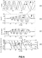
- the present invention is at least partly based on the following insights (see e.g. the waveforms of FIG. 5 applicable to the system of FIG. 1 ):
- the combination of these features provide unique properties to the position sensor system of being highly accurate (fine positioning), having a large measurement range (despite the high accuracy), being robust against an external disturbance field, and being robust against demagnetization.
- FIG. 1(a) is a schematic block-diagram of an exemplary linear position sensor system 100 according to an embodiment of the present invention.
- the sensor device 102 of FIG. 1 is arranged at a substantially constant distance H from the magnetic structure 101, for example in the order of about 0.5 to about 5.0 mm, and can be moved in the X-direction, substantially parallel to a surface of the magnetic structure, hence maintaining a constant distance "H" from the magnetic structure.
- the magnetic structure 101 comprises magnetic material which is magnetised in a particular manner.
- FIG. 1(a) shows a vertical cross-section of the magnetic structure, and the arrows show that the remanent magnetic field inside the magnetic material is oriented either in the positive Z-direction, or the negative Z-direction, hence perpendicular to the direction of movement X.
- the magnetic structure 101 has a plurality of magnetic poles P1, P2, P3, ... which are not located equidistantly, but the distances between centers of adjacent poles vary. Preferably the distances vary strict monotonically, implying inter alia that all distances are different.
- the magnetic structure 101 has 10 magnetic poles P1 .. P10, and in the example of FIG. 1(c) the magnetic structure 101 has seven magnetic poles, but of course the present invention is not limited thereto, and a magnetic structure with a larger or smaller number of poles can also be used, for example any number in the range from 3 to 50, or from 4 to 50, or from 5 to 50, or any number in the range from 3 to 30, or any number in the range from 4 to 20.
- the distance d1 between the first pole P1 and the second pole P2 is smaller than the distance d2 between the second pole P2 and the third pole P3, etc.
- the distance monotonically increases from the left of FIG. 1(a) to the right of FIG. 1(a) , meaning that d1 ⁇ d2 ⁇ d3 ⁇ ... ⁇ d9.
- the inventors found that based on the signals which can be measured by the sensor device 102, the position of the sensor device 102 on the X-axis can be uniquely determined, and with high accuracy (e.g. with a higher accuracy than would be possible if the magnetic structure 101 would contain only two or only three or only four equidistant poles), as will be explained further, when discussing FIG. 5 .
- the distance d[i+1] may be chosen to be substantially equal to the distance d[i] multiplied by a factor F chosen in the range from about 103% to 200%, depending on the application.
- the factor F may be constant over the entire length of the magnetic structure 101, but that is not absolutely required. In other embodiments, the factor F may vary for each pair, or for some of the pairs.
- the factor F is constant and about equal to 111%, but other values could also be used, for example approximately 103% or approximately 104% or approximately 105% or approximately 106% or approximately 107% or approximately 108% or approximately 109% or approximately 110% or approximately 111% or approximately 112% or approximately 114% or approximately 116% or approximately 118% or approximately 120% or approximately 125% or approximately 130% or approximately 135% or approximately 140% or approximately 145% or approximately 150% or approximately 160% or approximately 170% or approximately 180% or approximately 190% or approximately 200%.
- the impact hereof will become clear when discussing FIG. 5 .
- the distance d9 of the magnetic structure shown in FIG. 1(a) is about 2.3 times larger than the distance d1
- the sensor device 102 is oriented such that its semiconductor substrate is substantially perpendicular to the orientation of the remanent magnetic field inside the magnetic structure.
- coordinate axes X, Y, Z can be considered fixedly attached to the magnetic structure.
- the magnetic sensor is preferably configured to measure one or more magnetic field components Bx in the X-direction, oriented parallel to the semiconductor substrate, which can therefore be referred to as "in-plane” magnetic field component(s) for the sensor device of FIG. 1 , and for measuring one or more magnetic field components Bz in the Z-direction, perpendicular to the semiconductor substrate, which can therefore be referred to as "out-of-plane” magnetic field component(s) for the sensor device.
- in-plane magnetic field components
- Bz perpendicular to the semiconductor substrate
- FIG. 1(c) shows a perspective view for a magnetic structure having seven magnet poles, to better illustrate the preferred relative position of the magnetic structure 101 and the sensor device 102.
- FIG. 2 shows a variant of FIG. 1 , where the sensor device 152 is oriented such that its semiconductor substrate is substantially parallel to the remanent magnetic field inside the magnetic structure.
- orthogonal axes X, Y, Z are fixed to the magnetic structure, and assuming that orthogonal axes U, V, W are fixed to the sensor device, the skilled reader will understand that, if the U-axis is parallel to the X-axis, and the V-axis is parallel to the Z-axis, and the W-axis is parallel to the Y-axis, the magnetic field components Bu and Bv correspond to the magnetic field components Bx and Bz, respectively, relative to the magnetic structure.
- the sensor device 152 is configured for measuring in-plane field components Bu1, Bv1, Bu2, Bv2, oriented parallel to the semiconductor substrate, and for calculating a first gradient dBu/du and a second gradient dBv/du.
- the magnetic material is magnetised substantially in the movement direction (e.g. in the direction of the longitudinal axis), e.g. the positive X-axis or the negative X-axis.
- FIG. 3 is a schematic block-diagram of an exemplary angular position sensor system 200 according to an embodiment of the present invention.
- the magnetic structure 201 has a plurality of magnetic poles, in the example of FIG. 3 ten poles, P1, P2, ... P10, which poles P1, P2, .... are not located equidistantly, but the angular distances ⁇ 1, ⁇ 2, ... between centres of adjacent poles vary, such that ⁇ 1 ⁇ ⁇ 2 ⁇ ... ⁇ ⁇ 9 (see also FIG. 11 ).
- the structure may be axially magnetized, or the magnetization may be in-plane (e.g. oriented radially, or oriented tangentially), or the structure may be isotropically magnetized in the Z-direction.
- the inventors found that based on the magnetic signals which can be measured by the sensor device 202, the angular position ⁇ of the sensor device 202 with respect to a reference position of the magnetic structure 201 can be uniquely determined, and with high accuracy (e.g. larger than would be possible if the magnetic structure would contain only three or only four poles).
- the sensor device 202 is located at an "off-axis position" (i.e. not located on the rotation axis, but at a non-zero distance Rs therefrom, larger than 1 mm, e.g. at least 2 mm or at least 3 mm) and is oriented such that its semiconductor substrate is substantially perpendicular to the rotation axis of the magnetic structure.
- a first coordinate system with three orthogonal axes X, Y, Z is fixed to the magnetic structure, and a second coordinate system with three orthogonal axes U, V, W is fixed to the sensor device.
- the sensor device 202 is preferably oriented such that the U-axis is tangential to an imaginary circle around the rotation axis, and such that the W-axis of the sensor device is parallel to the Z-axis of the magnetic structure.
- the magnetic signals Bu and Bw of FIG. 3 are comparable to the signals Bx and Bz of FIG. 1(a) , and likewise, the gradient signals dBu/du and dBw/du are comparable to the signals dBx/dx and dBz/dx of FIG. 1(a) .
- the same sensor elements can be used in the sensor device 202 of FIG. 3 and the sensor device 102 of FIG. 1 , examples of which are illustrated for example in FIG. 6(a) and FIG. 6(b) , but the present invention is not limited hereto, and other sensor elements may also be used.
- FIG. 4 shows a variant of FIG. 3 , where the sensor device 252 is oriented such that its semiconductor substrate is substantially parallel to the remanent magnetic field inside the magnetic structure.
- the sensor device 252 is preferably oriented such that the U-axis is tangential to an imaginary circle around the rotation axis, and such that the V-axis of the sensor device is parallel to the Z-axis of the magnetic structure.
- the magnetic signals Bu and Bv of FIG. 4 are comparable to the signals Bu and Bv of FIG. 2 , and thus the gradient signals derived therefrom are also comparable.
- sensor elements can be used in the sensor device 252 of FIG. 4 and the sensor device 152 of FIG. 2 , an examples of which is illustrated in FIG. 7 , but the present invention is not limited hereto, and other sensor elements may also be used, for example four vertical Hall elements, or a plurality of magneto-resistive elements.
- FIG. 5(a) to FIG. 5(d) shows signals related to the exemplary linear position system of FIG. 1 , illustrating some of the principles of the present invention.
- FIG. 5(a) shows the remanent magnetic field Brx, Brz inside the magnetic material. It is noted that the remanent magnetization can be along Brz and Brx, or along Brz only, or along Brx only.
- FIG. 5(b) shows the magnetic field components Bx (indicated by a black square), Bz (indicated by a black circle) at a predefined distance "H" outside of the magnetic material, as can be measured by the sensor device 102.
- the drawing also shows (in dotted line) the value
- which is calculated here as: B sqrt Bx ⁇ Bx + Bz ⁇ Bz
- is a relatively smooth signal which (at least over a portion of the measurement range) monotonically increases with X (although that is not absolutely required for the present invention to work). It was found that if the centres of the poles are located further apart, the magnetic field strength measured by the sensor device (at a relatively small constant distance H) increases.
- FIG. 5(c) shows the spatial derivative dBx/dx of the in-plane field component Bx (indicated by a black square), and shows the spatial derivative dBz/dx of the out-of-plane magnetic field component Bz (indicated by a black circle).
- FIG. 5(c) shows the spatial derivative dBx/dx of the in-plane field component Bx (indicated by a black square), and shows the spatial derivative dBz/dx of the out-of-plane magnetic field component Bz (indicated by a black circle).
- 5(c) also shows (in dotted line) the value
- which is calculated here as: dB sqrt dBx / dx ⁇ dBx / x + dBz / dx ⁇ dBz / dx
- is also a relatively smooth signal which (at least over a portion of the measurement range) is substantially constant (although that is not absolutely required for the present invention to work).
- the inventors also came to the idea of calculating a first signal "Sc" based on, e.g. as a function of the in-plane magnetic field component Bx and the out-of-plane magnetic field component Bz, more particularly, as the ratio of the signal
- the signal Sf looks like a "sawtooth-function", but with non-constant teeth. This signal can be used as a fine indicator (within each tooth) for the position X of the sensor device 102, but as can be seen, the range of each tooth is only a subrange of the total range.
- a unique position X of the sensor device 102 can be defined on the X-axis, with large accuracy. Moreover, since the signal Sf is based on gradient signals, this position is highly insensitive to a (constant) external disturbance field Bext.
- the point C (white star) corresponds to a value Sc of approximately 0.93
- the point D black star
- the values of Sc for a plurality of positions may be determined during calibration, and may for example be stored in a non-volatile memory, or may be stored as a piecewise linear function, or in any other suitable way.
- the value Sc is slightly sensitive to an external disturbance field, hence the actual value Sc may differ from the stored (or interpolated) value Sc would have at point C or point D, because of the external disturbance field. It is noted however that the external disturbance field needs to be quite high before the algorithm described above "selects the wrong tooth". Hence, the algorithm described above is quite robust against an external disturbance field (of moderate strength).
- the tolerance margin can be appreciated to be equal to about half the step ⁇ . Thus, the larger this step ⁇ , the more tolerant the sensor system is against an external disturbance field. Having the benefit of this disclosure, the skilled person will now understand that, increasing the number of poles (for a given total range) corresponds to decreasing this tolerance against external field disturbances. However, as long as the actual external disturbance field is smaller than this tolerance margin, the sensor provides a highly accurate unique position over a relatively large range (in the example spanning multiple poles).
- the signals on the left end of the magnetic structure and on the right end of the magnetic structure cannot be used, but in practice the skilled person can make the magnetic structure slightly larger than the range to be measured.
- of the magnetic field components increases as the distance between adjacent pole pairs increases (see FIG. 5b ), and the in-plane derivatives of these magnetic field components is substantially constant (see FIG. 5c ), this is not absolutely required, and the invention will also work if d[Bxz]/dx varies without the derivative itself being substantially constant, as long as the combination of the fine signal Sf and the coarse signal Sc, e.g. in the form of two values in the look-up table, are unique, i.e. correspond to a single position. This also means that the invention will still work, even if the coarse signal Sc (see FIG. 5d ) does not monotonically increase, but has a constant portion, or even has a local dip, as long as the combination of the two signals Sf and Sc is unique.
- FIG. 6(a) is a schematic block-diagram showing an exemplary arrangement of sensor elements as can be incorporated in the linear position sensor device 102 of FIG. 1 and/or in the angular position sensor device 202 of FIG. 3 .
- This sensor arrangement shown in FIG. 6(a) contains four collinear horizontal Hall elements (indicated by black squares) and two IMC elements (indicated by gray circles).
- such structures can be used to determine (e.g. measure and/or calculate) an in-plane magnetic field component Bx oriented in a direction parallel to the semiconductor substrate, and an out-of-plane magnetic field component Bz oriented in a direction perpendicular to the semiconductor substrate of the sensor device.
- FIG. 6(b) is a schematic block-diagram showing another exemplary arrangement of sensor elements as can be incorporated in the linear position sensor device 102 of FIG. 1 and/or in the angular position sensor device 202 of FIG. 3 .
- the sensor arrangement shown in FIG. 6(b) contains two horizontal Hall elements HH1, HH2 (without IMC) spaced apart over a distance ⁇ X1, and two vertical Hall elements VH1, VH2 spaced apart over a second distance ⁇ X2, which may be equal to ⁇ X1 or larger than ⁇ X1, or smaller than ⁇ X1.
- the two horizontal Hall elements HH1, HH2 can be used to measure the Bz field at two different positions, and the two vertical Hall elements VH1, VH2 can be used to measure the Bx field at two different locations.
- FIG. 7(a) is a schematic block-diagram showing another exemplary arrangement of sensor elements as can be incorporated in the linear position sensor device 152 of FIG. 2 and/or in the angular position sensor device 252 of FIG. 4 .
- the sensor arrangement shown in FIG. 7 contains two IMC structures, each with four horizontal Hall elements, and can be seen as a variant of the sensor arrangement of FIG. 6(a) , in which:
- FIG. 7(b) shows a sensor arrangement comprises four vertical Hall elements, as can be incorporated in the linear position sensor device 152 of FIG. 2 and/or in the angular position sensor device 252 of FIG. 4 .
- the sensor arrangement comprises:
- FIG. 8 shows an exemplary schematic block diagram of a sensor device 800, as can be used in the linear position sensor system 100 of FIG. 1 , or the angular position sensor system 200 of FIG. 3 .
- the position sensor device 800 shown in FIG. 8 comprises a plurality of four magnetic sensor elements 811, 812, 813, 814, for example four horizontal Hall elements (as shown in FIG. 6a ) or two horizontal Hall elements and two vertical Hall elements (as shown in FIG. 6b ), or four vertical Hall elements (as shown in FIG. 7b ) for providing a first and a second magnetic field component (e.g. Bx and Bz, or Bu and Bv), but the invention is not limited thereto, and the sensor device may comprise more than four magnetic sensor elements, for example eight magnetic sensor elements (e.g. eight horizontal Hall elements, as shown in FIG. 7a ).
- the position sensor device 800 further comprises a processing unit 815 adapted for calculating a coarse signal "Sc" based on said at least first and second magnetic field component, for example using formula [4.11] or [5.11] or [6.11].
- the processing unit 815 is further adapted for determining a first spatial gradient and a second spatial gradient (e.g. dBx/dx and dBz/dx or dBu/du and dBv/du), and for calculating a fine signal "Sf" based on these spatial gradients for example using formula [4.12] or [5.12] or [6.12].
- the processing unit 815 is further adapted for determining said linear position X or said angular position ⁇ based on both the coarse signal Sc and on the fine signal Sf, for example using a look-up table and interpolation, or in any other suitable way.
- the processing unit 815 may comprise a programmable device, adapted for performing a method of determining said linear or angular position, as described above, or as illustrated in FIG. 14 .
- FIG. 9 illustrates a first method of producing a magnetic structure 901 as may be used in the linear position sensor system of FIG. 1 or FIG. 2 .
- This method is based on magnetising a magnetic material using a relatively strong current (a technique known per se in the art, but not for this particular topology).
- a relatively strong current a technique known per se in the art, but not for this particular topology.
- What is shown is a top view of a surface of a structure comprising magnetic material.
- an electrical conductor is positioned as shown, forming a zig-zag, and a relatively large current is injected through the conductor, inducing a large magnetic field, which enters the page of the drawing (indicated by x), and which comes out of the page of the drawing (indicated by •), only a few vectors are shown.
- FIG. 10 illustrates a second method of producing a magnetic structure as may be used in the linear position sensor system of FIG. 1 or FIG. 2 .
- Such a magnet structure can be produced for example by a technique for making bonded magnets. This technique is known per se, albeit for equidistant magnet poles. Typically a mixture known as "feed stock" containing magnetic particles is injected in a cavity of a mold, and one or more permanent magnets are located in close vicinity of, but outside the cavity during molding.
- FIG. 11 illustrates a method of producing a magnetic structure as may be used in the angular position sensor system of FIG. 3 or FIG. 4 , based on magnetising a magnetic material.
- a similar technique as described in FIG. 9 is used here, mutatis mutandis. It is noted that in this drawing it is clearly shown that ⁇ 1 ⁇ ⁇ 2 ⁇ ⁇ 3 ⁇ ... ⁇ ⁇ 9. In this particular example, the number of poles (which can be seen by a sensor device facing one of the ring shaped surfaces, as illustrated in FIG.
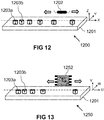
- FIG. 12 illustrates yet another magnetic structure 1201 as may be used in the angular position sensor system of FIG. 1 .
- the magnetic structure comprises a non-magnetic structure functioning as a holder, with a plurality of openings, and in each opening a permanent magnet is inserted.
- the magnets can be axially magnetized, or the magnetization can also be in-plane or isotropic.
- the magnets may be cylindrical magnets, but that is not absolutely required.
- the cylindrical magnets may have a single diameter (as shown), or may have different diameters (not shown). What is important is that the distance between the centers of the magnets varies.
- the sensor device 1202 is oriented such that its semiconductor substrate is perpendicular to the direction of the remanent magnetic field inside the magnets, and such that its internal X-axis (along which the sensor elements are spaced apart, e.g. as illustrated for in FIG. 6a or FIG. 6b , is parallel to the X-direction of the magnetic structure, along which the discrete magnets are located.
- FIG. 13 shows a variant of FIG. 12 , where the sensor device 1252 is oriented such that its semiconductor substrate is parallel to the direction of the remanent magnetic field inside the magnets, and such that its internal U-axis (along which the sensor elements are spaced apart, e.g. as illustrated in FIG. 7a or FIG. 7b , is parallel to the X-direction of the magnetic structure, along which the discrete magnets are located.
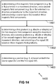
- FIG. 14 illustrates a method 1400 of determining a position of a sensor device (see for example FIG. 8 with a sensor configuration of FIG. 6a or FIG. 6b or FIG. 7a or FIG. 7b ) relative to a magnetic structure (see for example the magnetic structure of FIG. 1 or FIG. 2 or FIG. 3 or FIG. 4 or FIG. 12 or FIG. 13 ) having a plurality of poles, and said sensor device comprising a plurality of magnetic sensors or sensor elements, and wherein the magnetic structure is movable (e.g. linearly or rotationally) relative to the sensor device or vice versa, and wherein a distance (Xpp, ⁇ pp) between centres of adjacent poles varies along a movement direction or along the movement trajectory.
- a distance Xpp, ⁇ pp
- the method comprises the steps of:
Landscapes
- Physics & Mathematics (AREA)
- General Physics & Mathematics (AREA)
- Condensed Matter Physics & Semiconductors (AREA)
- Transmission And Conversion Of Sensor Element Output (AREA)
Claims (15)
- Positionssensorsystem (100; 150; 200; 250; 1200; 1250) zum Bestimmen einer Position (X, α) einer Sensorvorrichtung (102; 152; 202; 252; 1202; 1252) relativ zu einer Magnetstruktur (101; 201; 1201), wobei das System Folgendes umfasst:- die Magnetstruktur (101; 201; 1201), die mehrere Pole umfasst;- die Sensorvorrichtung, die mehrere Magnetsensoren zum Bestimmen einer oder mehrerer Magnetfeldkomponenten und zum Bestimmen eines Magnetfeldgradienten umfasst;- wobei die Magnetstruktur relativ zu der Sensorvorrichtung in einer Bewegungsrichtung oder entlang einer Bewegungstrajektorie beweglich ist (X, a), oder umgekehrt;dadurch gekennzeichnet, dass- eine Distanz (Xpp, αpp) zwischen Zentren von benachbarten Polen der Magnetstruktur entlang der Bewegungsrichtung oder entlang der Bewegungstrajektorie variiert;- die Sensorvorrichtung eingerichtet ist:a) zum Bestimmen einer oder mehrerer erster Magnetfeldkomponenten (Bx1, Bx2), orientiert in einer ersten Richtung (X; U) im Wesentlichen parallel zu der Bewegungsrichtung oder tangential zu der Bewegungstrajektorie, und einer oder mehrerer zweiter Magnetfeldkomponenten (Bz1, Bz2), orientiert in einer zweiten Richtung (Z; V) im Wesentlichen senkrecht zu der ersten Richtung (X; U), und zum Berechnen eines Grobsignals (Sc) basierend auf diesen Magnetfeldkomponenten (Bx1, Bx2, Bz1, Bz2); undb) zum Bestimmen eines ersten Gradienten (dBx/dx; dBu/du) der einen oder der mehreren ersten Magnetfeldkomponenten entlang der ersten Richtung (X; U), und eines zweiten Gradienten (dBz/dx; dBv/du) der einen oder mehreren zweiten Magnetfeldkomponenten (Bz; Bv) entlang der ersten Richtung (X; U), und zum Berechnen eines Feinsignals (Sf) basierend auf diesen Gradienten; undc) zum Bestimmen der Position (X, α) basierend sowohl auf dem Grobsignal (Sc) als auch auf dem Feinsignal (Sf).
- Positionssensorsystem (100; 150; 200; 250; 1200; 1250) nach Anspruch 1, wobei die Sensorvorrichtung relativ zu der Magnetstruktur bei einer im Wesentlichen konstanten Distanz (H) von der Magnetstruktur bewegbar angeordnet ist.
- Positionssensorsystem nach einem der vorhergehenden Ansprüche,
wobei die Magnetstruktur eine Zusammenstellung von mehreren diskreten Permanentmagneten ist; oder
wobei die Magnetstruktur ein monolithisches Magnetmaterial umfasst, dass derart magnetisiert ist, dass es mehrere in entgegengesetzten Richtungen orientierte Pole aufweist. - Positionssensorsystem (100; 150; 1200; 1250) nach einem der vorhergehenden Ansprüche, wobei die Magnetstruktur eine längliche Gestalt aufweist, die eine lineare Achse aufweist.
- Positionssensorsystem nach einem der Ansprüche 1 bis 3, wobei die Magnetstruktur eine gekrümmte Gestalt aufweist, die eine gekrümmte Achse aufweist.
- Positionssensorsystem nach einem der vorhergehenden Ansprüche, wobei das remanente Magnetfeld (Brz) im Innern des Magnetmaterials im Wesentlichen senkrecht zu der ersten Richtung oder im Wesentlichen parallel zu der zweiten Richtung orientiert ist.
- Positionssensorsystem nach einem der Ansprüche 4 bis 6, wobei die Distanz (Xpp, αpp) zwischen Zentren von benachbarten Polen entlang der linearen oder gekrümmten Achse streng monoton variiert.
- Positionssensorsystem nach einem der vorhergehenden Ansprüche,
wobei die Sensorvorrichtung einen ersten integrierten Magnetkonzentrator (IMC1) umfasst und ein erstes und ein zweites horizontales Hall-Element (HP1, HP2), die an entgegengesetzten Seiten des ersten Magnetkonzentrators (IMC1) angeordnet sind, und einen zweiten integrierten Magnetkonzentrator (IMC2), der sich bei einer vordefinierten Distanz (Δx) von dem ersten Magnetkonzentrator (IMC1) befindet, und ein drittes und ein viertes horizontales Hall-Element (HP3, HP4), die an entgegengesetzten Seiten des zweiten Magnetkonzentrators (IMC2) angeordnet sind, wobei das erste, das zweite, das dritte und das vierte horizontale Hall-Element kollinear sind; oder
wobei die Sensorvorrichtung einen ersten integrierten Magnetkonzentrator (IMC1) umfasst und eine erste Gruppe von vier horizontalen Hall-Elementen, die nahe eines Rands des ersten Magnetkonzentrators (IMC1) angeordnet sind, und einen zweiten integrierten Magnetkonzentrator IMC2), der sich bei einer vordefinierten Distanz (Δx) von dem ersten Magnetkonzentrator (IMC1) befindet, und eine zweite Gruppe von vier horizontalen Hall-Elementen, die nahe einem Rand des zweiten Magnetkonzentrators (IMC2) angeordnet sind. - Positionssensorsystem nach einem der Ansprüche 1 bis 7,
wobei die Sensorvorrichtung zwei horizontale Hall-Elemente (HH1, HH2) umfasst, die in der ersten Richtung (X) über eine erste Distanz (Δx1) beabstandet sind;
und zwei vertikale Hall-Elemente (VH1, VH2) umfasst, die in der ersten Richtung (X) über eine zweite Distanz (Δx2) beabstandet sind. - Positionssensorsystem nach einem der vorhergehenden Ansprüche,
wobei die Sensorvorrichtung eingerichtet ist zum Berechnen des Grobsignals (Sc) gemäß einer der folgenden Formeln:

- Positionssensorsystem nach einem der vorhergehenden Ansprüche,
wobei die Sensorvorrichtung eingerichtet ist zum Berechnen des Feinsignals (Sf) gemäß der folgenden Formel:
- Positionssensorsystem nach einem der vorhergehenden Ansprüche,
wobei die Sensorvorrichtung eingerichtet ist zum Bestimmen der Position durch Bestimmen mehrerer von mindestens zwei Kandidatenpositionen (xA, xB), basierend auf dem Feinsignal (Sf), und dann Auswählen einer dieser Kandidatenpositionen (xA, xB), basierend auf dem Grobsignal (Sc). - Verfahren zum Bestimmen einer Position (X, α) einer Sensorvorrichtung (102; 152; 202; 252; 1202; 1252) relativ zu einer Magnetstruktur (101; 201; 1201) die mehrere Pole aufweist, wobei die Sensorvorrichtung mehrere Magnetsensoren zum Bestimmen einer oder mehrerer Magnetfeldkomponenten und zum Bestimmen eines Magnetfeldgradienten umfasst, wobei die Magnetstruktur relativ zu der Sensorvorrichtung in einer Bewegungsrichtung oder entlang einer Bewegungstrajektorie beweglich ist (X, a), oder umgekehrt;
dadurch gekennzeichnet, dass- eine Distanz (Xpp, αpp) zwischen Zentren von benachbarten Polen der Magnetstruktur entlang der Bewegungsrichtung oder entlang der Bewegungstrajektorie variiert;und das Verfahren die folgenden Schritte umfasst:a) Bestimmen einer oder mehrerer erster Magnetfeldkomponenten (Bx1, Bx2), orientiert in einer ersten Richtung (X; U) im Wesentlichen parallel zu der Bewegungsrichtung oder im Wesentlichen tangential zu der Bewegungstrajektorie, und einer oder mehrerer zweiter Magnetfeldkomponenten (Bz1, Bz2), orientiert in einer zweiten Richtung (Z; V) im Wesentlichen senkrecht zu der ersten Richtung (X; U), und Berechnen eines Grobsignals (Sc) basierend auf diesen Magnetfeldkomponenten (Bx1, Bx2, Bz1, Bz2); undb) Bestimmen eines ersten Gradienten (dBx/dx) der einen oder der mehreren ersten Magnetfeldkomponenten entlang der ersten Richtung (X; U) und eines zweiten Gradienten (dBz/dx; dBv/du) der einen oder mehreren zweiten Magnetfeldkomponenten entlang der ersten Richtung (X; U), und Berechnen eines Feinsignals (Sf) basierend auf diesen Gradienten;c) Bestimmen der Position (X, α) basierend sowohl auf dem Grobsignal (Sc) als auch auf dem Feinsignal (Sf). - Verfahren nach Anspruch 13,
wobei Schritt a) Folgendes umfasst: Berechnen des Grobsignals (Sc) gemäß einer der folgenden Formeln:

und/oder wobei Schritt b) Folgendes umfasst: Berechnen des Feinsignals (Sf) gemäß der folgenden Formel:
und/oder wobei Schritt c) Folgendes umfasst: Bestimmen der Position durch Bestimmen mehrerer von mindestens zwei Kandidatenpositionen (xA, xB), basierend auf dem Feinsignal (Sf), und dann Auswählen einer der Kandidatenpositionen (xA, xB), basierend auf dem gemessenen Grobsignal (Sc). - Positionssensorvorrichtung (800), geeignet zur Verwendung in einem Positionssensorsystem nach einem der Ansprüche 1 bis 12, wobei die Positionssensorvorrichtung Folgendes umfasst:- ein Halbleitersubstrat;- mehrere Sensorelemente (811, 812, 813, 814) zum Bestimmen erster Magnetfeldkomponenten (Bx1, Bx2; Bu1, Bu2), orientiert in einer ersten Richtung (X; U) im Wesentlichen parallel zu dem Substrat, an mindestens zwei verschiedenen Stellen (X1, X2) die über eine vorbestimmte Distanz (Δx) entlang der ersten Richtung beabstandet sind, und zum Bestimmen zweiter Magnetfeldkomponenten (Bz1, Bz2; Bv1, Bv2), orientiert in einer zweiten Richtung (Z; V) im Wesentlichen senkrecht zu der ersten Richtung, im Wesentlichen parallel zu dem Substrat oder im Wesentlichen senkrecht zu dem Substrat, an mindestens zwei verschiedenen Stellen, die über eine vorbestimmte Distanz (Δx) entlang der ersten Richtung beabstandet sind;- ein Verarbeitungseinheit (815), eingerichtet zum Berechnen eines Grobsignals (Sc) basierend auf mindestens einigen dieser Magnetfeldkomponenten (Bx1, Bx2, Bz1, Bz2);- wobei die Verarbeitungseinheit ferner eingerichtet ist zum Bestimmen eines ersten Gradienten (dBx/dx; dBu/du) der ersten Magnetfeldkomponente (Bx) entlang der ersten Richtung und eines zweiten Gradienten (dBz/dx; dBv/du) der zweiten Magnetfeldkomponente (Bz; Bv) entlang der ersten Richtung, und zum Berechnen eines Feinsignals (Sf) basierend auf diesen Gradienten;- wobei die Verarbeitungseinheit (815) ferner eingerichtet ist zum Bestimmen der Position (X, α) basierend sowohl auf dem Grobsignal (Sc) als auch auf dem Feinsignal (Sf).
Applications Claiming Priority (1)
| Application Number | Priority Date | Filing Date | Title |
|---|---|---|---|
| EP18205705 | 2018-11-12 |
Publications (2)
| Publication Number | Publication Date |
|---|---|
| EP3650816A1 EP3650816A1 (de) | 2020-05-13 |
| EP3650816B1 true EP3650816B1 (de) | 2021-01-27 |
Family
ID=64277593
Family Applications (1)
| Application Number | Title | Priority Date | Filing Date |
|---|---|---|---|
| EP19207358.3A Active EP3650816B1 (de) | 2018-11-12 | 2019-11-06 | System und verfahren für magnetischen positionssensor |
Country Status (3)
| Country | Link |
|---|---|
| US (1) | US11092461B2 (de) |
| EP (1) | EP3650816B1 (de) |
| CN (1) | CN111174682B (de) |
Families Citing this family (18)
| Publication number | Priority date | Publication date | Assignee | Title |
|---|---|---|---|---|
| US11573072B2 (en) * | 2018-12-13 | 2023-02-07 | Analog Devices International Unlimited Company | Magnetic position determination systems and methods |
| US11326868B2 (en) * | 2019-05-23 | 2022-05-10 | Melexis Technologies Sa | Magnetic position sensor system, device, magnet and method |
| EP3845864B1 (de) * | 2019-12-30 | 2023-11-22 | Melexis Technologies SA | System und verfahren für magnetischen positionssensor |
| US11293784B2 (en) * | 2020-05-06 | 2022-04-05 | Melexis Technologies Sa | Magnetic position sensor system and method |
| EP3919922B1 (de) * | 2020-06-02 | 2024-05-29 | Melexis Technologies SA | Stromsensorsystem |
| EP3955436B1 (de) * | 2020-08-14 | 2024-01-17 | Schneider Electric Industries SAS | Linearmotorsystem und betriebsverfahren für ein solches |
| CN111895900A (zh) * | 2020-08-24 | 2020-11-06 | 杰克缝纫机股份有限公司 | 一种线性位移高精度测量装置及缝纫机 |
| EP4002503B1 (de) * | 2020-11-23 | 2024-04-17 | Melexis Technologies SA | Halbleiterbauelement mit integriertem magnetflusskonzentrator und verfahren zur herstellung davon |
| EP4239295B1 (de) | 2020-12-23 | 2024-11-13 | Melexis Technologies SA | Positionssensorsystem und -verfahren |
| KR20230150302A (ko) * | 2021-02-03 | 2023-10-30 | 모트엑스 엘티디. | 고해상도 절대형 벡터 인코더 |
| EP4105768B1 (de) * | 2021-06-18 | 2024-03-06 | Melexis Technologies SA | Vorrichtung und verfahren zur bestimmung der orientierung eines magneten und joystick |
| DE102021118347B4 (de) | 2021-07-15 | 2026-01-29 | Infineon Technologies Ag | Systeme; vorrichtungen und verfahren zur magnetischen positionserkennung |
| EP4170292B1 (de) | 2021-10-25 | 2024-04-03 | Melexis Technologies SA | Sensorvorrichtung und system mit nichtlinearitätskompensation |
| EP4495552A3 (de) | 2021-11-25 | 2025-04-23 | Melexis Technologies SA | Positionssensor mit haupt- und noniusspuren |
| EP4212828B1 (de) * | 2022-01-13 | 2024-12-04 | Goodix Technology (HK) Company Limited | Lineare positionsdetektoranordnung mit langem hub |
| CN116559735B (zh) * | 2023-05-12 | 2024-05-03 | 苏州纳芯微电子股份有限公司 | 磁传感器、状态检测装置及方法 |
| EP4484987A1 (de) | 2023-06-28 | 2025-01-01 | Melexis Technologies SA | Magnetsensorstruktur, -vorrichtung und -system |
| EP4560267B1 (de) * | 2023-11-21 | 2026-04-29 | Melexis Technologies SA | Lineare magnetische positionssensorschaltung |
Family Cites Families (8)
| Publication number | Priority date | Publication date | Assignee | Title |
|---|---|---|---|---|
| JP5136009B2 (ja) * | 2007-11-13 | 2013-02-06 | 沖電気工業株式会社 | 磁気センサ検出信号の検出方法及び検出装置 |
| US8593136B2 (en) | 2008-11-27 | 2013-11-26 | Micronas Gmbh | Measuring apparatus for the detection of a relative movement |
| EP2256521A1 (de) * | 2009-05-25 | 2010-12-01 | Fraunhofer-Gesellschaft zur Förderung der angewandten Forschung e.V. | Verfahren und Anordnung zur magnetischen Positionsbestimmung |
| US8717010B2 (en) * | 2011-08-19 | 2014-05-06 | Infineon Technologies Ag | Magnetic position sensors, systems and methods |
| DE102011116545A1 (de) * | 2011-10-21 | 2013-04-25 | Micronas Gmbh | Integrierte Magnetfeldmessvorrichtung |
| GB2505226A (en) | 2012-08-23 | 2014-02-26 | Melexis Technologies Nv | Arrangement, method and sensor for measuring an absolute angular position using a multi-pole magnet |
| US9863788B2 (en) | 2014-09-10 | 2018-01-09 | Infineon Technologies Ag | Linear position and rotary position magnetic sensors, systems, and methods |
| DE102017222674A1 (de) | 2016-12-29 | 2018-07-05 | Robert Bosch Gmbh | Wegsensor |
-
2019
- 2019-11-06 EP EP19207358.3A patent/EP3650816B1/de active Active
- 2019-11-08 US US16/678,336 patent/US11092461B2/en active Active
- 2019-11-11 CN CN201911094501.XA patent/CN111174682B/zh active Active
Non-Patent Citations (1)
| Title |
|---|
| None * |
Also Published As
| Publication number | Publication date |
|---|---|
| US11092461B2 (en) | 2021-08-17 |
| US20200149925A1 (en) | 2020-05-14 |
| CN111174682B (zh) | 2022-04-26 |
| CN111174682A (zh) | 2020-05-19 |
| EP3650816A1 (de) | 2020-05-13 |
Similar Documents
| Publication | Publication Date | Title |
|---|---|---|
| EP3650816B1 (de) | System und verfahren für magnetischen positionssensor | |
| US11796305B2 (en) | Magnetic position sensor system, device, magnet and method | |
| EP3321638B1 (de) | Messung einer absoluten winkelposition | |
| US10697800B2 (en) | Multi-dimensional measurement using magnetic sensors and related systems, methods, and integrated circuits | |
| JP6926209B2 (ja) | 距離センサ | |
| EP3588011B1 (de) | Gegenüber störfeldern robustes positionssensorsystem und verfahren | |
| US20170241803A1 (en) | Magnetic position sensor | |
| EP4397939A2 (de) | Magnetisches positionssensorsystem und verfahren | |
| US11293784B2 (en) | Magnetic position sensor system and method | |
| US12352606B2 (en) | Magnetic position sensor system, method and device with error detection | |
| CN103472414A (zh) | 磁传感器装置 | |
| US20230213357A1 (en) | Magnetic position sensor device, method and system, with error detection | |
| EP3407009B1 (de) | Näherungssensor | |
| EP3907475B1 (de) | System und verfahren zur magnetischen positionsbestimmung | |
| US20250102288A1 (en) | Device, method, and system for detecting rotation angle in electronic equipment | |
| CN121261602A (zh) | 云台电机转子角度定位方法、装置、设备及存储介质 | |
| CN119475169A (zh) | 数据处理方法及装置、电子设备、计算机程序产品 | |
| JP2017129432A (ja) | 近接センサ |
Legal Events
| Date | Code | Title | Description |
|---|---|---|---|
| PUAI | Public reference made under article 153(3) epc to a published international application that has entered the european phase |
Free format text: ORIGINAL CODE: 0009012 |
|
| STAA | Information on the status of an ep patent application or granted ep patent |
Free format text: STATUS: THE APPLICATION HAS BEEN PUBLISHED |
|
| AK | Designated contracting states |
Kind code of ref document: A1 Designated state(s): AL AT BE BG CH CY CZ DE DK EE ES FI FR GB GR HR HU IE IS IT LI LT LU LV MC MK MT NL NO PL PT RO RS SE SI SK SM TR |
|
| AX | Request for extension of the european patent |
Extension state: BA ME |
|
| STAA | Information on the status of an ep patent application or granted ep patent |
Free format text: STATUS: REQUEST FOR EXAMINATION WAS MADE |
|
| 17P | Request for examination filed |
Effective date: 20200518 |
|
| RBV | Designated contracting states (corrected) |
Designated state(s): AL AT BE BG CH CY CZ DE DK EE ES FI FR GB GR HR HU IE IS IT LI LT LU LV MC MK MT NL NO PL PT RO RS SE SI SK SM TR |
|
| GRAP | Despatch of communication of intention to grant a patent |
Free format text: ORIGINAL CODE: EPIDOSNIGR1 |
|
| STAA | Information on the status of an ep patent application or granted ep patent |
Free format text: STATUS: GRANT OF PATENT IS INTENDED |
|
| INTG | Intention to grant announced |
Effective date: 20200917 |
|
| GRAS | Grant fee paid |
Free format text: ORIGINAL CODE: EPIDOSNIGR3 |
|
| GRAA | (expected) grant |
Free format text: ORIGINAL CODE: 0009210 |
|
| STAA | Information on the status of an ep patent application or granted ep patent |
Free format text: STATUS: THE PATENT HAS BEEN GRANTED |
|
| AK | Designated contracting states |
Kind code of ref document: B1 Designated state(s): AL AT BE BG CH CY CZ DE DK EE ES FI FR GB GR HR HU IE IS IT LI LT LU LV MC MK MT NL NO PL PT RO RS SE SI SK SM TR |
|
| REG | Reference to a national code |
Ref country code: GB Ref legal event code: FG4D |
|
| REG | Reference to a national code |
Ref country code: CH Ref legal event code: EP |
|
| REG | Reference to a national code |
Ref country code: AT Ref legal event code: REF Ref document number: 1358768 Country of ref document: AT Kind code of ref document: T Effective date: 20210215 |
|
| REG | Reference to a national code |
Ref country code: IE Ref legal event code: FG4D |
|
| REG | Reference to a national code |
Ref country code: DE Ref legal event code: R096 Ref document number: 602019002400 Country of ref document: DE |
|
| REG | Reference to a national code |
Ref country code: NL Ref legal event code: MP Effective date: 20210127 |
|
| REG | Reference to a national code |
Ref country code: LT Ref legal event code: MG9D |
|
| REG | Reference to a national code |
Ref country code: AT Ref legal event code: MK05 Ref document number: 1358768 Country of ref document: AT Kind code of ref document: T Effective date: 20210127 |
|
| PG25 | Lapsed in a contracting state [announced via postgrant information from national office to epo] |
Ref country code: PT Free format text: LAPSE BECAUSE OF FAILURE TO SUBMIT A TRANSLATION OF THE DESCRIPTION OR TO PAY THE FEE WITHIN THE PRESCRIBED TIME-LIMIT Effective date: 20210527 Ref country code: NO Free format text: LAPSE BECAUSE OF FAILURE TO SUBMIT A TRANSLATION OF THE DESCRIPTION OR TO PAY THE FEE WITHIN THE PRESCRIBED TIME-LIMIT Effective date: 20210427 Ref country code: LT Free format text: LAPSE BECAUSE OF FAILURE TO SUBMIT A TRANSLATION OF THE DESCRIPTION OR TO PAY THE FEE WITHIN THE PRESCRIBED TIME-LIMIT Effective date: 20210127 Ref country code: GR Free format text: LAPSE BECAUSE OF FAILURE TO SUBMIT A TRANSLATION OF THE DESCRIPTION OR TO PAY THE FEE WITHIN THE PRESCRIBED TIME-LIMIT Effective date: 20210428 Ref country code: FI Free format text: LAPSE BECAUSE OF FAILURE TO SUBMIT A TRANSLATION OF THE DESCRIPTION OR TO PAY THE FEE WITHIN THE PRESCRIBED TIME-LIMIT Effective date: 20210127 Ref country code: BG Free format text: LAPSE BECAUSE OF FAILURE TO SUBMIT A TRANSLATION OF THE DESCRIPTION OR TO PAY THE FEE WITHIN THE PRESCRIBED TIME-LIMIT Effective date: 20210427 Ref country code: HR Free format text: LAPSE BECAUSE OF FAILURE TO SUBMIT A TRANSLATION OF THE DESCRIPTION OR TO PAY THE FEE WITHIN THE PRESCRIBED TIME-LIMIT Effective date: 20210127 |
|
| PG25 | Lapsed in a contracting state [announced via postgrant information from national office to epo] |
Ref country code: SE Free format text: LAPSE BECAUSE OF FAILURE TO SUBMIT A TRANSLATION OF THE DESCRIPTION OR TO PAY THE FEE WITHIN THE PRESCRIBED TIME-LIMIT Effective date: 20210127 Ref country code: RS Free format text: LAPSE BECAUSE OF FAILURE TO SUBMIT A TRANSLATION OF THE DESCRIPTION OR TO PAY THE FEE WITHIN THE PRESCRIBED TIME-LIMIT Effective date: 20210127 Ref country code: AT Free format text: LAPSE BECAUSE OF FAILURE TO SUBMIT A TRANSLATION OF THE DESCRIPTION OR TO PAY THE FEE WITHIN THE PRESCRIBED TIME-LIMIT Effective date: 20210127 Ref country code: PL Free format text: LAPSE BECAUSE OF FAILURE TO SUBMIT A TRANSLATION OF THE DESCRIPTION OR TO PAY THE FEE WITHIN THE PRESCRIBED TIME-LIMIT Effective date: 20210127 Ref country code: LV Free format text: LAPSE BECAUSE OF FAILURE TO SUBMIT A TRANSLATION OF THE DESCRIPTION OR TO PAY THE FEE WITHIN THE PRESCRIBED TIME-LIMIT Effective date: 20210127 |
|
| PG25 | Lapsed in a contracting state [announced via postgrant information from national office to epo] |
Ref country code: IS Free format text: LAPSE BECAUSE OF FAILURE TO SUBMIT A TRANSLATION OF THE DESCRIPTION OR TO PAY THE FEE WITHIN THE PRESCRIBED TIME-LIMIT Effective date: 20210527 |
|
| REG | Reference to a national code |
Ref country code: DE Ref legal event code: R097 Ref document number: 602019002400 Country of ref document: DE |
|
| PG25 | Lapsed in a contracting state [announced via postgrant information from national office to epo] |
Ref country code: SM Free format text: LAPSE BECAUSE OF FAILURE TO SUBMIT A TRANSLATION OF THE DESCRIPTION OR TO PAY THE FEE WITHIN THE PRESCRIBED TIME-LIMIT Effective date: 20210127 Ref country code: CZ Free format text: LAPSE BECAUSE OF FAILURE TO SUBMIT A TRANSLATION OF THE DESCRIPTION OR TO PAY THE FEE WITHIN THE PRESCRIBED TIME-LIMIT Effective date: 20210127 Ref country code: EE Free format text: LAPSE BECAUSE OF FAILURE TO SUBMIT A TRANSLATION OF THE DESCRIPTION OR TO PAY THE FEE WITHIN THE PRESCRIBED TIME-LIMIT Effective date: 20210127 |
|
| PG25 | Lapsed in a contracting state [announced via postgrant information from national office to epo] |
Ref country code: DK Free format text: LAPSE BECAUSE OF FAILURE TO SUBMIT A TRANSLATION OF THE DESCRIPTION OR TO PAY THE FEE WITHIN THE PRESCRIBED TIME-LIMIT Effective date: 20210127 Ref country code: RO Free format text: LAPSE BECAUSE OF FAILURE TO SUBMIT A TRANSLATION OF THE DESCRIPTION OR TO PAY THE FEE WITHIN THE PRESCRIBED TIME-LIMIT Effective date: 20210127 Ref country code: SK Free format text: LAPSE BECAUSE OF FAILURE TO SUBMIT A TRANSLATION OF THE DESCRIPTION OR TO PAY THE FEE WITHIN THE PRESCRIBED TIME-LIMIT Effective date: 20210127 |
|
| PLBE | No opposition filed within time limit |
Free format text: ORIGINAL CODE: 0009261 |
|
| STAA | Information on the status of an ep patent application or granted ep patent |
Free format text: STATUS: NO OPPOSITION FILED WITHIN TIME LIMIT |
|
| 26N | No opposition filed |
Effective date: 20211028 |
|
| PG25 | Lapsed in a contracting state [announced via postgrant information from national office to epo] |
Ref country code: ES Free format text: LAPSE BECAUSE OF FAILURE TO SUBMIT A TRANSLATION OF THE DESCRIPTION OR TO PAY THE FEE WITHIN THE PRESCRIBED TIME-LIMIT Effective date: 20210127 Ref country code: AL Free format text: LAPSE BECAUSE OF FAILURE TO SUBMIT A TRANSLATION OF THE DESCRIPTION OR TO PAY THE FEE WITHIN THE PRESCRIBED TIME-LIMIT Effective date: 20210127 |
|
| PG25 | Lapsed in a contracting state [announced via postgrant information from national office to epo] |
Ref country code: IT Free format text: LAPSE BECAUSE OF FAILURE TO SUBMIT A TRANSLATION OF THE DESCRIPTION OR TO PAY THE FEE WITHIN THE PRESCRIBED TIME-LIMIT Effective date: 20210127 |
|
| PG25 | Lapsed in a contracting state [announced via postgrant information from national office to epo] |
Ref country code: IS Free format text: LAPSE BECAUSE OF FAILURE TO SUBMIT A TRANSLATION OF THE DESCRIPTION OR TO PAY THE FEE WITHIN THE PRESCRIBED TIME-LIMIT Effective date: 20210527 |
|
| PG25 | Lapsed in a contracting state [announced via postgrant information from national office to epo] |
Ref country code: MC Free format text: LAPSE BECAUSE OF FAILURE TO SUBMIT A TRANSLATION OF THE DESCRIPTION OR TO PAY THE FEE WITHIN THE PRESCRIBED TIME-LIMIT Effective date: 20210127 |
|
| PG25 | Lapsed in a contracting state [announced via postgrant information from national office to epo] |
Ref country code: LU Free format text: LAPSE BECAUSE OF NON-PAYMENT OF DUE FEES Effective date: 20211106 Ref country code: BE Free format text: LAPSE BECAUSE OF NON-PAYMENT OF DUE FEES Effective date: 20211130 |
|
| REG | Reference to a national code |
Ref country code: BE Ref legal event code: MM Effective date: 20211130 |
|
| PG25 | Lapsed in a contracting state [announced via postgrant information from national office to epo] |
Ref country code: IE Free format text: LAPSE BECAUSE OF NON-PAYMENT OF DUE FEES Effective date: 20211106 |
|
| P01 | Opt-out of the competence of the unified patent court (upc) registered |
Effective date: 20230517 |
|
| PG25 | Lapsed in a contracting state [announced via postgrant information from national office to epo] |
Ref country code: CY Free format text: LAPSE BECAUSE OF FAILURE TO SUBMIT A TRANSLATION OF THE DESCRIPTION OR TO PAY THE FEE WITHIN THE PRESCRIBED TIME-LIMIT Effective date: 20210127 |
|
| REG | Reference to a national code |
Ref country code: CH Ref legal event code: PL |
|
| PG25 | Lapsed in a contracting state [announced via postgrant information from national office to epo] |
Ref country code: LI Free format text: LAPSE BECAUSE OF NON-PAYMENT OF DUE FEES Effective date: 20221130 Ref country code: HU Free format text: LAPSE BECAUSE OF FAILURE TO SUBMIT A TRANSLATION OF THE DESCRIPTION OR TO PAY THE FEE WITHIN THE PRESCRIBED TIME-LIMIT; INVALID AB INITIO Effective date: 20191106 Ref country code: CH Free format text: LAPSE BECAUSE OF NON-PAYMENT OF DUE FEES Effective date: 20221130 |
|
| PG25 | Lapsed in a contracting state [announced via postgrant information from national office to epo] |
Ref country code: SI Free format text: LAPSE BECAUSE OF FAILURE TO SUBMIT A TRANSLATION OF THE DESCRIPTION OR TO PAY THE FEE WITHIN THE PRESCRIBED TIME-LIMIT Effective date: 20210127 |
|
| PG25 | Lapsed in a contracting state [announced via postgrant information from national office to epo] |
Ref country code: MK Free format text: LAPSE BECAUSE OF FAILURE TO SUBMIT A TRANSLATION OF THE DESCRIPTION OR TO PAY THE FEE WITHIN THE PRESCRIBED TIME-LIMIT Effective date: 20210127 |
|
| PG25 | Lapsed in a contracting state [announced via postgrant information from national office to epo] |
Ref country code: TR Free format text: LAPSE BECAUSE OF FAILURE TO SUBMIT A TRANSLATION OF THE DESCRIPTION OR TO PAY THE FEE WITHIN THE PRESCRIBED TIME-LIMIT Effective date: 20210127 |
|
| GBPC | Gb: european patent ceased through non-payment of renewal fee |
Effective date: 20231106 |
|
| PG25 | Lapsed in a contracting state [announced via postgrant information from national office to epo] |
Ref country code: MT Free format text: LAPSE BECAUSE OF FAILURE TO SUBMIT A TRANSLATION OF THE DESCRIPTION OR TO PAY THE FEE WITHIN THE PRESCRIBED TIME-LIMIT Effective date: 20210127 |
|
| PG25 | Lapsed in a contracting state [announced via postgrant information from national office to epo] |
Ref country code: GB Free format text: LAPSE BECAUSE OF NON-PAYMENT OF DUE FEES Effective date: 20231106 |
|
| PG25 | Lapsed in a contracting state [announced via postgrant information from national office to epo] |
Ref country code: GB Free format text: LAPSE BECAUSE OF NON-PAYMENT OF DUE FEES Effective date: 20231106 |
|
| PG25 | Lapsed in a contracting state [announced via postgrant information from national office to epo] |
Ref country code: NL Free format text: LAPSE BECAUSE OF FAILURE TO SUBMIT A TRANSLATION OF THE DESCRIPTION OR TO PAY THE FEE WITHIN THE PRESCRIBED TIME-LIMIT Effective date: 20210127 |
|
| PGFP | Annual fee paid to national office [announced via postgrant information from national office to epo] |
Ref country code: DE Payment date: 20251022 Year of fee payment: 7 |
|
| PGFP | Annual fee paid to national office [announced via postgrant information from national office to epo] |
Ref country code: FR Payment date: 20251022 Year of fee payment: 7 |