EP3653363B1 - Utilisation d'un adaptateur de distribution pour un dispositif d'écriture de structures tridimensionnelles par lithographie laser - Google Patents
Utilisation d'un adaptateur de distribution pour un dispositif d'écriture de structures tridimensionnelles par lithographie laser Download PDFInfo
- Publication number
- EP3653363B1 EP3653363B1 EP19202490.9A EP19202490A EP3653363B1 EP 3653363 B1 EP3653363 B1 EP 3653363B1 EP 19202490 A EP19202490 A EP 19202490A EP 3653363 B1 EP3653363 B1 EP 3653363B1
- Authority
- EP
- European Patent Office
- Prior art keywords
- fluid
- lithography
- use according
- space
- lens
- Prior art date
- Legal status (The legal status is an assumption and is not a legal conclusion. Google has not performed a legal analysis and makes no representation as to the accuracy of the status listed.)
- Active
Links
Images

Classifications
-
- B—PERFORMING OPERATIONS; TRANSPORTING
- B29—WORKING OF PLASTICS; WORKING OF SUBSTANCES IN A PLASTIC STATE IN GENERAL
- B29C—SHAPING OR JOINING OF PLASTICS; SHAPING OF MATERIAL IN A PLASTIC STATE, NOT OTHERWISE PROVIDED FOR; AFTER-TREATMENT OF THE SHAPED PRODUCTS, e.g. REPAIRING
- B29C64/00—Additive manufacturing, i.e. manufacturing of three-dimensional [3D] objects by additive deposition, additive agglomeration or additive layering, e.g. by 3D printing, stereolithography or selective laser sintering
- B29C64/10—Processes of additive manufacturing
- B29C64/106—Processes of additive manufacturing using only liquids or viscous materials, e.g. depositing a continuous bead of viscous material
-
- G—PHYSICS
- G02—OPTICS
- G02B—OPTICAL ELEMENTS, SYSTEMS OR APPARATUS
- G02B21/00—Microscopes
- G02B21/02—Objectives
-
- B—PERFORMING OPERATIONS; TRANSPORTING
- B29—WORKING OF PLASTICS; WORKING OF SUBSTANCES IN A PLASTIC STATE IN GENERAL
- B29C—SHAPING OR JOINING OF PLASTICS; SHAPING OF MATERIAL IN A PLASTIC STATE, NOT OTHERWISE PROVIDED FOR; AFTER-TREATMENT OF THE SHAPED PRODUCTS, e.g. REPAIRING
- B29C64/00—Additive manufacturing, i.e. manufacturing of three-dimensional [3D] objects by additive deposition, additive agglomeration or additive layering, e.g. by 3D printing, stereolithography or selective laser sintering
- B29C64/10—Processes of additive manufacturing
- B29C64/106—Processes of additive manufacturing using only liquids or viscous materials, e.g. depositing a continuous bead of viscous material
- B29C64/124—Processes of additive manufacturing using only liquids or viscous materials, e.g. depositing a continuous bead of viscous material using layers of liquid which are selectively solidified
- B29C64/129—Processes of additive manufacturing using only liquids or viscous materials, e.g. depositing a continuous bead of viscous material using layers of liquid which are selectively solidified characterised by the energy source therefor, e.g. by global irradiation combined with a mask
- B29C64/135—Processes of additive manufacturing using only liquids or viscous materials, e.g. depositing a continuous bead of viscous material using layers of liquid which are selectively solidified characterised by the energy source therefor, e.g. by global irradiation combined with a mask the energy source being concentrated, e.g. scanning lasers or focused light sources
-
- B—PERFORMING OPERATIONS; TRANSPORTING
- B29—WORKING OF PLASTICS; WORKING OF SUBSTANCES IN A PLASTIC STATE IN GENERAL
- B29C—SHAPING OR JOINING OF PLASTICS; SHAPING OF MATERIAL IN A PLASTIC STATE, NOT OTHERWISE PROVIDED FOR; AFTER-TREATMENT OF THE SHAPED PRODUCTS, e.g. REPAIRING
- B29C64/00—Additive manufacturing, i.e. manufacturing of three-dimensional [3D] objects by additive deposition, additive agglomeration or additive layering, e.g. by 3D printing, stereolithography or selective laser sintering
- B29C64/20—Apparatus for additive manufacturing; Details thereof or accessories therefor
- B29C64/205—Means for applying layers
- B29C64/209—Heads; Nozzles
-
- B—PERFORMING OPERATIONS; TRANSPORTING
- B29—WORKING OF PLASTICS; WORKING OF SUBSTANCES IN A PLASTIC STATE IN GENERAL
- B29C—SHAPING OR JOINING OF PLASTICS; SHAPING OF MATERIAL IN A PLASTIC STATE, NOT OTHERWISE PROVIDED FOR; AFTER-TREATMENT OF THE SHAPED PRODUCTS, e.g. REPAIRING
- B29C64/00—Additive manufacturing, i.e. manufacturing of three-dimensional [3D] objects by additive deposition, additive agglomeration or additive layering, e.g. by 3D printing, stereolithography or selective laser sintering
- B29C64/20—Apparatus for additive manufacturing; Details thereof or accessories therefor
- B29C64/264—Arrangements for irradiation
- B29C64/268—Arrangements for irradiation using laser beams; using electron beams [EB]
-
- B—PERFORMING OPERATIONS; TRANSPORTING
- B29—WORKING OF PLASTICS; WORKING OF SUBSTANCES IN A PLASTIC STATE IN GENERAL
- B29C—SHAPING OR JOINING OF PLASTICS; SHAPING OF MATERIAL IN A PLASTIC STATE, NOT OTHERWISE PROVIDED FOR; AFTER-TREATMENT OF THE SHAPED PRODUCTS, e.g. REPAIRING
- B29C64/00—Additive manufacturing, i.e. manufacturing of three-dimensional [3D] objects by additive deposition, additive agglomeration or additive layering, e.g. by 3D printing, stereolithography or selective laser sintering
- B29C64/30—Auxiliary operations or equipment
- B29C64/307—Handling of material to be used in additive manufacturing
- B29C64/321—Feeding
-
- B—PERFORMING OPERATIONS; TRANSPORTING
- B29—WORKING OF PLASTICS; WORKING OF SUBSTANCES IN A PLASTIC STATE IN GENERAL
- B29C—SHAPING OR JOINING OF PLASTICS; SHAPING OF MATERIAL IN A PLASTIC STATE, NOT OTHERWISE PROVIDED FOR; AFTER-TREATMENT OF THE SHAPED PRODUCTS, e.g. REPAIRING
- B29C64/00—Additive manufacturing, i.e. manufacturing of three-dimensional [3D] objects by additive deposition, additive agglomeration or additive layering, e.g. by 3D printing, stereolithography or selective laser sintering
- B29C64/30—Auxiliary operations or equipment
- B29C64/307—Handling of material to be used in additive manufacturing
- B29C64/321—Feeding
- B29C64/336—Feeding of two or more materials
-
- B—PERFORMING OPERATIONS; TRANSPORTING
- B29—WORKING OF PLASTICS; WORKING OF SUBSTANCES IN A PLASTIC STATE IN GENERAL
- B29C—SHAPING OR JOINING OF PLASTICS; SHAPING OF MATERIAL IN A PLASTIC STATE, NOT OTHERWISE PROVIDED FOR; AFTER-TREATMENT OF THE SHAPED PRODUCTS, e.g. REPAIRING
- B29C64/00—Additive manufacturing, i.e. manufacturing of three-dimensional [3D] objects by additive deposition, additive agglomeration or additive layering, e.g. by 3D printing, stereolithography or selective laser sintering
- B29C64/30—Auxiliary operations or equipment
- B29C64/35—Cleaning
-
- B—PERFORMING OPERATIONS; TRANSPORTING
- B29—WORKING OF PLASTICS; WORKING OF SUBSTANCES IN A PLASTIC STATE IN GENERAL
- B29C—SHAPING OR JOINING OF PLASTICS; SHAPING OF MATERIAL IN A PLASTIC STATE, NOT OTHERWISE PROVIDED FOR; AFTER-TREATMENT OF THE SHAPED PRODUCTS, e.g. REPAIRING
- B29C64/00—Additive manufacturing, i.e. manufacturing of three-dimensional [3D] objects by additive deposition, additive agglomeration or additive layering, e.g. by 3D printing, stereolithography or selective laser sintering
- B29C64/30—Auxiliary operations or equipment
- B29C64/364—Conditioning of environment
-
- B—PERFORMING OPERATIONS; TRANSPORTING
- B33—ADDITIVE MANUFACTURING TECHNOLOGY
- B33Y—ADDITIVE MANUFACTURING, i.e. MANUFACTURING OF THREE-DIMENSIONAL [3D] OBJECTS BY ADDITIVE DEPOSITION, ADDITIVE AGGLOMERATION OR ADDITIVE LAYERING, e.g. BY 3D PRINTING, STEREOLITHOGRAPHY OR SELECTIVE LASER SINTERING
- B33Y10/00—Processes of additive manufacturing
-
- B—PERFORMING OPERATIONS; TRANSPORTING
- B33—ADDITIVE MANUFACTURING TECHNOLOGY
- B33Y—ADDITIVE MANUFACTURING, i.e. MANUFACTURING OF THREE-DIMENSIONAL [3D] OBJECTS BY ADDITIVE DEPOSITION, ADDITIVE AGGLOMERATION OR ADDITIVE LAYERING, e.g. BY 3D PRINTING, STEREOLITHOGRAPHY OR SELECTIVE LASER SINTERING
- B33Y30/00—Apparatus for additive manufacturing; Details thereof or accessories therefor
-
- B—PERFORMING OPERATIONS; TRANSPORTING
- B33—ADDITIVE MANUFACTURING TECHNOLOGY
- B33Y—ADDITIVE MANUFACTURING, i.e. MANUFACTURING OF THREE-DIMENSIONAL [3D] OBJECTS BY ADDITIVE DEPOSITION, ADDITIVE AGGLOMERATION OR ADDITIVE LAYERING, e.g. BY 3D PRINTING, STEREOLITHOGRAPHY OR SELECTIVE LASER SINTERING
- B33Y40/00—Auxiliary operations or equipment, e.g. for material handling
-
- G—PHYSICS
- G02—OPTICS
- G02B—OPTICAL ELEMENTS, SYSTEMS OR APPARATUS
- G02B21/00—Microscopes
- G02B21/33—Immersion oils, or microscope systems or objectives for use with immersion fluids
-
- G—PHYSICS
- G02—OPTICS
- G02B—OPTICAL ELEMENTS, SYSTEMS OR APPARATUS
- G02B27/00—Optical systems or apparatus not provided for by any of the groups G02B1/00 - G02B26/00, G02B30/00
- G02B27/0006—Optical systems or apparatus not provided for by any of the groups G02B1/00 - G02B26/00, G02B30/00 with means to keep optical surfaces clean, e.g. by preventing or removing dirt, stains, contamination, condensation
-
- G—PHYSICS
- G03—PHOTOGRAPHY; CINEMATOGRAPHY; ANALOGOUS TECHNIQUES USING WAVES OTHER THAN OPTICAL WAVES; ELECTROGRAPHY; HOLOGRAPHY
- G03F—PHOTOMECHANICAL PRODUCTION OF TEXTURED OR PATTERNED SURFACES, e.g. FOR PRINTING, FOR PROCESSING OF SEMICONDUCTOR DEVICES; MATERIALS THEREFOR; ORIGINALS THEREFOR; APPARATUS SPECIALLY ADAPTED THEREFOR
- G03F7/00—Photomechanical, e.g. photolithographic, production of textured or patterned surfaces, e.g. printing surfaces; Materials therefor, e.g. comprising photoresists; Apparatus specially adapted therefor
- G03F7/16—Coating processes; Apparatus therefor
-
- G—PHYSICS
- G03—PHOTOGRAPHY; CINEMATOGRAPHY; ANALOGOUS TECHNIQUES USING WAVES OTHER THAN OPTICAL WAVES; ELECTROGRAPHY; HOLOGRAPHY
- G03F—PHOTOMECHANICAL PRODUCTION OF TEXTURED OR PATTERNED SURFACES, e.g. FOR PRINTING, FOR PROCESSING OF SEMICONDUCTOR DEVICES; MATERIALS THEREFOR; ORIGINALS THEREFOR; APPARATUS SPECIALLY ADAPTED THEREFOR
- G03F7/00—Photomechanical, e.g. photolithographic, production of textured or patterned surfaces, e.g. printing surfaces; Materials therefor, e.g. comprising photoresists; Apparatus specially adapted therefor
- G03F7/20—Exposure; Apparatus therefor
- G03F7/2051—Exposure without an original mask, e.g. using a programmed deflection of a point source, by scanning, by drawing with a light beam, using an addressed light or corpuscular source
- G03F7/2053—Exposure without an original mask, e.g. using a programmed deflection of a point source, by scanning, by drawing with a light beam, using an addressed light or corpuscular source using a laser
-
- G—PHYSICS
- G03—PHOTOGRAPHY; CINEMATOGRAPHY; ANALOGOUS TECHNIQUES USING WAVES OTHER THAN OPTICAL WAVES; ELECTROGRAPHY; HOLOGRAPHY
- G03F—PHOTOMECHANICAL PRODUCTION OF TEXTURED OR PATTERNED SURFACES, e.g. FOR PRINTING, FOR PROCESSING OF SEMICONDUCTOR DEVICES; MATERIALS THEREFOR; ORIGINALS THEREFOR; APPARATUS SPECIALLY ADAPTED THEREFOR
- G03F7/00—Photomechanical, e.g. photolithographic, production of textured or patterned surfaces, e.g. printing surfaces; Materials therefor, e.g. comprising photoresists; Apparatus specially adapted therefor
- G03F7/70—Microphotolithographic exposure; Apparatus therefor
- G03F7/70416—2.5D lithography
-
- B—PERFORMING OPERATIONS; TRANSPORTING
- B29—WORKING OF PLASTICS; WORKING OF SUBSTANCES IN A PLASTIC STATE IN GENERAL
- B29K—INDEXING SCHEME ASSOCIATED WITH SUBCLASSES B29B, B29C OR B29D, RELATING TO MOULDING MATERIALS OR TO MATERIALS FOR MOULDS, REINFORCEMENTS, FILLERS OR PREFORMED PARTS, e.g. INSERTS
- B29K2995/00—Properties of moulding materials, reinforcements, fillers, preformed parts or moulds
- B29K2995/0037—Other properties
- B29K2995/0072—Roughness, e.g. anti-slip
- B29K2995/0073—Roughness, e.g. anti-slip smooth
Definitions
- the invention relates to a use of a dispenser attachment for lenses in the field of laser lithography.
- laser lithography is also known as stereo lithography or direct laser typing.
- structures are written using a writing beam into a usually initially liquid, photosensitive substance, which is referred to in this context as lithography fluid.
- the laser radiation of the writing beam triggers a local solidification effect in the lithography fluid. Solidification occurs, for example, due to local polymerization of the lithography fluid induced by photon absorption.
- lithography fluids are also referred to as photoresists.
- the technology of laser lithography or direct laser writing is advantageously used in the production of micro- or nanostructures when a high level of precision is desired and at the same time freedom of design and flexibility in shaping are to be maintained.
- different structures can be written without the structure being predetermined by a mask or something similar.
- the desired overall structure is created by sequentially writing a series of substructures, which then add up to form the desired structure.
- the overall structures are usually written layer by layer or slice by slice.
- the writing beam hits the surface of a volume of lithography fluid and leads to local solidification on the surface.
- an additional layer of lithography fluid is applied in an application step after a layer has been written. This can be achieved, for example, by gradually lowering a substrate with the structure to be written onto it into a bath of lithography fluid and structuring the surface using the writing beam.
- Another approach exploits the physical principle of two-photon polymerization or generally multi-photon polymerization to achieve solidification of lithography fluid even within a volume of lithography fluid, i.e. also below the surface.
- the writing beam and the lithography fluid are coordinated in such a way that a solidification effect occurs with the help of non-linear effects.
- the writing beam is a spectral range that cannot normally trigger a solidification effect in the lithography fluid.
- the lithography fluid and the writing beam can be coordinated in such a way that induced solidification can only occur through radiation that has a wavelength that corresponds to a fraction (in particular an integer fraction) of the wavelength of the writing beam actually used.
- a solidification process is only possible with the simultaneous absorption of two or more photons of the writing beam (two-photon polymerization or multi-photon polymerization).
- multi-photon polymerization refers to induced polymerization through the simultaneous absorption of two or more than two photons.
- multi-photon absorption for the present description also includes the process of "two-photon absorption".
- the conditions required for multi-photon polymerization are usually only achieved in a zone of increased intensity. This zone of increased intensity is provided in a focus area of the writing beam.
- the focus area is a beam waist of the writing beam, which is created by suitable optics (e.g. beam guidance optics, beam shaping optics and/or a lens).
- suitable optics e.g. beam guidance optics, beam shaping optics and/or a lens.
- the focus area can then be moved through a volume of lithography fluid in accordance with geometry description data and locally trigger a solidification process.
- a corresponding technology is used, for example, in the DE 101 11 422 A1 which shows 3D laser lithography using multi-photon polymerization within a bath of lithography material in a container.
- the device described here has an exit optic for focusing the laser beam on a focus area within the container.
- Other lithography processes using multi-photon polymerization are known from US 6 713 772 B2 and US 2012/0218535 A1 known.
- immersion oil dispensers in the form of an attachment for microscopy objectives are known.
- immersion oil dispensers in the form of an attachment for microscopy objectives.
- these dispensers have a housing which, when attached to an objective, defines a fluid chamber which opens into an exit slit which usually surrounds the lens of the objective in a ring-like manner.
- Immersion oil is then provided in the fluid space and can exit through the exit slit.
- Immersion in immersion oil is carried out in the field of microscopy for the purpose of improving the image quality and resolution. From the US 9 927 702 B2 A semi-submersible microscopy objective is also known.
- the task is to release the lithography fluid in a suitable manner during laser lithography or direct laser writing and to supply it if necessary.
- the dispenser attachment is used in a device for writing three-dimensional structures using laser lithography in a lithography fluid.
- a device comprises a laser beam source for emitting a writing beam and usually a substrate on which a volume of lithography fluid can be received and made available.
- the lithography fluid can be locally solidified by means of the writing beam to produce a structure.
- the device also comprises various optical components, for example a beam guidance and steering device and an objective for guiding the writing beam and for forming a focus area of the writing beam in the lithography fluid.
- the objective is particularly important.
- the objective comprises an objective housing with an end lens through which the writing beam exits the objective.
- the term end lens generally refers to the optical element which forms the transition from the objective to the environment.
- the end lens can be a lens in the true sense of the word (e.g. converging lens). However, the end lens does not necessarily have to have an optical lens effect, but can also be designed as a end window, for example.
- the dispenser attachment used comprises a particularly cap-like dispenser housing, which is designed to be placed on the lens or on the lens housing.
- the dispenser housing is designed in such a way that when placed on, a fluid space is formed between the lens housing and the dispenser housing.
- the fluid space opens into an outlet gap, which is formed between the dispenser housing and the lens's end lens. Fluid can flow from the fluid space into a space in front of the end lens through the outlet gap.
- the dispenser housing has an opening in the area of the closure lens such that an annular gap is formed between an opening edge and the closure lens.
- the dispenser attachment also comprises a fluid access into the fluid space for supplying fluids into the fluid space so that fluid can continuously exit through the exit gap.
- a lithography fluid is provided which is matched to the laser beam source in such a way that solidification can only take place in the focus area and only using a two-photon process or, more generally, a multi-photon process.
- the lithography fluid is then fed into the fluid space through the fluid access.
- the use then comprises the step of applying a volume of lithography fluid through the exit gap.
- the application is to be understood here as the application of lithography fluid through the exit gap into an external spatial area.
- the volume of lithography fluid is applied to the substrate or to an already existing volume of lithography fluid.
- the writing beam or more specifically the focus area of the writing beam, is introduced through the lens into the volume of lithography fluid.
- the laser lithography device is expanded and improved in such a way that structures can be produced continuously.
- the use described offers the advantage, for example, that after a structure has been written on a substrate, this can be removed and a new substrate can be provided. In particular, it is not necessary to apply a layer or volume of lithography fluid to the substrate before writing a structure. In this respect, pretreatment steps can be reduced and simplified. This enables a production process with a high throughput rate with the laser lithography devices of the type mentioned.
- the lithography fluid can be stored in a separate reservoir, which is connected to the fluid chamber via a fluid line. If necessary, a fluid pump can be provided which pumps the fluid from the reservoir into the fluid chamber. This largely prevents exposure of the lithography fluid to the ambient atmosphere. This can reduce contamination of the lithography fluid and undesirable degradation of the lithography fluid. This improves the quality of the written structures.
- microscopy objectives such as those available as standard components for microscopes.
- a dispenser attachment can then be used, such as is used in the field of microscopy for the application of immersion oil with the aim of improving optical properties.
- the invention therefore relates to the use of a dispenser of the type mentioned for the purpose of applying lithography fluid.
- the focus area is positioned in particular in the area between a surface of the substrate and the final lens of the objective.
- the step of applying lithography fluid is carried out in such a way that the lithography fluid remains in contact with the end lens and the writing beam is introduced into the lithography fluid while it is still in contact with the end lens.
- the focus area is divided into a the final lens touching volume of lithography fluid is introduced. Since the local solidification of the lithography fluid in the focus area only takes place using a two-photon process or, more generally, a multi-photon process, the solidification in the focus area takes place at a distance from the final lens and not directly in the area of the lithography fluid volume that adheres to the final lens. This prevents the final lens from sticking due to solidified lithography fluid.
- the lithography fluid adheres directly to the final lens, an optical interface in the beam path between the final lens and the focus area is avoided (as would occur, for example, at a transition between air and lithography fluid or lens and air). This can reduce imaging errors that can lead to quality losses and inaccuracies in the written structure).
- the lithography fluid is made available in situ using the procedure described. The steps of applying and writing the structure can be carried out one after the other without interruption. To write extensive structures, for example, a drop of lithography fluid can first be applied, then writing can be done in the drop, and then lithography fluid can be added, thus creating more space for further structure sections.
- the application step is carried out in such a way that the lithography fluid is in contact with the substrate on the one hand and with the final lens on the other hand. Contact remains and the writing beam is introduced into the lithography fluid while the lithography fluid is in contact with the end lens and the substrate.
- the lithography fluid fills the space between the end lens and the substrate. A continuous drop is formed between the end lens and the substrate, which stabilizes the volume of liquid and the structures written in it.
- continuous writing of large structures is made possible by continuously moving the lens away from the substrate and continuously supplying lithography fluid. In particular, it can be prevented that the drop of lithography fluid breaks off from the lens.
- a first lithography fluid is provided and applied through the fluid space and the exit gap, and then - if necessary with the interposition of further steps - a second lithography fluid is provided and applied through the fluid space and the exit gap.
- the first lithography fluid and the second lithography fluid are different materials with, in particular, different material properties.
- a first structure can then be written in the lithography fluid with the writing beam.
- the second lithography fluid can then be applied and a second Substructures can be written. In this way, multi-material structures can be produced using this procedure.
- the two different lithography fluids can be applied one after the other and mixed with one another.
- the writing beam is then preferably introduced into a volume of mixed first lithography fluid and second lithography fluid.
- the procedure described thus makes it possible to specifically adapt material properties, for example by using different mixing ratios.
- the two lithography fluids can be mixed in various ways, for example by an intrinsic diffusion process or with the aid of mixing aids (for example a compressed air jet).
- a developer fluid is provided and the developer fluid is fed through the fluid access into the fluid space.
- the developer fluid is designed in particular to expose and/or harden the written three-dimensional structure.
- the developer fluid can be a solvent which is matched to the lithography fluid in such a way that only non-solidified lithography fluid is dissolved and solidified lithography fluid remains.
- the procedure described can be further developed by supplying a compressed gas to the fluid chamber.
- a step can then be provided in which the compressed gas exits through the outlet gap.
- This step can be provided at different times, for example before the first application of lithography fluid.
- impurities can be removed from the substrate.
- the compressed gas exits through the outlet gap after a volume of lithography fluid has been applied in order to distribute or displace the lithography fluid on the substrate.
- a cleaning fluid can be provided and fed into the fluid space and optionally expelled through the exit gap.
- the cleaning fluid is designed in particular in such a way that both unsolidified (liquid) and solidified lithography fluid is dissolved.
- the cleaning fluid is expelled through the exit gap in particular in such a way that the end lens is wetted with the cleaning fluid.
- the fluid space can be used to generate additional functionalities.
- light can be introduced into the fluid space, e.g. by means of a light guide that opens into the fluid space.
- the light then exits through the exit gap, depending on the design, and can be used to illuminate the substrate and/or an already applied volume of lithography fluid and/or an already written three-dimensional structure.
- This is advantageous because in direct laser writing methods, in situ image monitoring of the written structure is generally desirable. It is also conceivable that an image of the illuminated structure and/or the substrate is also recorded using the lens used for writing.
- the introduction of light can, for example, take place after the lithography fluid has been fed into the fluid space through the fluid access. In this case, the lithography fluid can contribute to the light being guided out of the fluid space through the exit gap.
- the penetration of light can, for example, take place through the fluid access or through a separate access into the fluid space.
- an immersion objective can be used as an objective.
- Such immersion objectives are known, for example, as accessories in microscopy and are used there to achieve better imaging qualities.
- an immersion objective is used which has a configuration that is adapted to the refractive index of the lithography fluid used.
- An advantageous dispenser attachment or an advantageous system comprising a dispenser attachment and a lens has a housing, in particular a cap-like housing, which is designed to be placed on the lens or the lens housing in such a way that a fluid space is formed and an exit gap is formed between the dispenser housing and the lens's end lens.
- a dispenser attachment also has a fluid access for supplying fluids into the fluid space.
- a particularly suitable dispenser attachment results from the fact that the dispenser housing is adapted to the lens in such a way that the exit gap is an annular gap around the end lens, the annular gap being delimited by a peripheral edge of the dispenser housing in such a way that the end lens protrudes beyond the dispenser housing. In particular, the end lens protrudes beyond the dispenser housing in the direction of the writing beam. When used as described above, this prevents structures that have already been written from colliding with the dispenser housing and thus becoming damaged when the lens is moved.
- a dispenser attachment or a system comprising a dispenser attachment and a lens that is particularly suitable for the use described also results from the fact that the dispenser housing has an inner wall and an outer wall that runs around the inner wall, so that the inner wall faces the lens housing and the fluid space is formed between the inner wall and the outer wall.
- the inner wall then preferably has a transmission window made of a fluid-tight and optically transparent material that faces the end lens.
- the transmission window is positioned opposite the end lens in the beam direction.
- the exit gap is preferably formed between the exit window and the outer wall.
- such a dispenser attachment has a double-walled dispenser housing and the fluid is guided between the inner wall and the outer wall. The transmission window prevents the end lens from coming into direct contact with the lithography fluid.
- the inner wall also prevents the lens housing and/or optical components of the lens from coming into contact with the lithography fluid. This prevents contamination.
- the inner wall and outer wall are preferably designed as essentially circular-cylindrical walls.
- the outer wall preferably runs coaxially around the inner wall.
- the beam path through the lens and dispenser attachment is preferably concentric through these walls.
- An advantageously usable dispenser attachment or an advantageously usable system comprising a dispenser attachment and a lens also results from the fact that the dispenser housing has at least one additional access to the fluid space.
- the additional access is in particular designed separately from the fluid access. Additional functions can be introduced into the fluid space through this access.
- the access can be designed to supply fluids (e.g. printing fluid) or different lithography fluids) or to supply light into the fluid space.
- the access can comprise a light guide, by means of which light from a preferably external light source can be introduced into the fluid space.
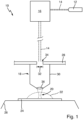
- the Figure 1 shows a sketched representation of a device 10 for writing three-dimensional structures using laser lithography in a lithography fluid, referred to as a laser lithography device 10 for short.
- the device 10 comprises a laser beam source 12 for emitting a writing beam 14 made of laser light.
- the writing beam 14 passes through, for example, a beam guiding and steering device 16, which forms a writing beam suitable for the purposes of laser lithography from the light emitted by the laser beam source 12 and, for example, deflects or moves the writing beam in accordance with geometry description data of a desired structure.
- the beam guiding and steering device 16 can interact with a control device (not shown).
- the writing beam 14 is converted into an output beam with a focus area 20 by means of an objective 18.
- the focus area 20 is designed in particular in the manner of a beam waist of the writing beam 14.
- the focus area 20 is introduced into a volume of lithography fluid 22 and, if necessary, moved in the volume according to the geometry description data for the desired structure.
- the writing beam 14 triggers a solidification reaction in the lithography fluid 22. So that the solidification reaction can also take place within the volume of the lithography fluid 22, i.e. below a surface of the lithography fluid 22, for the purposes of the present invention the lithography fluid 22 is matched to the writing beam 14 in such a way that the solidification can only take place in the focus area 20 and only by utilizing multi-photon absorption processes.
- the volume of lithography fluid 22 is applied to a substrate 24 in drop-like fashion.
- the volume of lithography fluid 22 can also be provided in a container or, as explained below, provided in the form of a drop that is in contact with the lens 18.
- the substrate 24 can be fixed to a substrate holder 26, which is designed to be displaceable in a writing plane, for example.
- the lens 18 can, for example, be mounted on a head plate 28 of the device 10. It is conceivable that the head plate 28 is also designed to be slightly displaceable with corresponding actuators.
- the design of the device 12 allows the focus region 20 to be displaced in three spatial directions within the volume of lithography fluid 22.
- the lens 18 comprises a lens housing 30, which is preferably mounted on the head plate 28 in such a way that an entrance aperture 32 of the lens 18 corresponds to a corresponding opening 34 of the head plate 28.
- the writing beam 14 is radiated through the opening 34 and the entrance aperture 32 in a beam direction.
- the lens 18 also comprises a closing lens 36, through which the writing beam 14 exits and forms the focus area 20.
- FIG. 1 The use of a dispenser attachment 38 in a device according to the type of Figure 1 is based on the Figures 2 to 4 These figures each show an example of a section of a device 10 of the Figure 1 shown type with detailed view in the area of the head plate 28 and the lens 18.
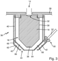
- the Figure 2 shows a dispenser attachment 38 with a dispenser housing 40, which can be placed on the lens 18 in such a way that the dispenser housing 40 surrounds the lens 18 at least in some areas.
- a fluid space 42 is delimited by the dispenser housing 40 or by the dispenser housing together with wall areas of the lens housing 30.
- the dispenser housing 40 has an opening pointing downwards (ie away from the head plate 28) such that an exit gap 44 is formed with the lens 18.
- the exit gap 44 is preferably designed such that it runs around the end lens 36, in particular in a ring-like manner.
- the exit gap 44 preferably borders directly on an edge of the end lens 36.
- the fluid space 42 thus opens into the environment through the exit gap 44.
- the volume of the fluid space 42 inside the dispenser housing 40 is limited and sealed by a sealing projection 46 pointing radially inward from the walls of the dispenser housing 40, such that when the dispenser housing 40 is placed on the lens 18, the sealing projection 46 rests against the lens housing 30 and thereby seals the fluid space 42.
- a corresponding ring seal 48 can be arranged in the sealing projection 46 to improve the tightness.
- the dispenser attachment 38 also comprises a fluid access 50 for supplying fluid into the fluid chamber 42.
- a fluid line 52 can be led through a corresponding sealing section 54 on the dispenser housing 40 and open into the fluid chamber 42.
- the lens 18 and the dispenser attachment 38 form a coordinated system.
- the lens 18 and the dispenser attachment 38 are mounted on a print head of the device 10 using coordinated mounting means.
- the head plate 28 can have a double-threaded ring 56, wherein the lens housing 30 is screwed into an internal thread of the double-threaded ring 56, and the dispenser housing 40 is screwed onto the opposite external thread of the double-threaded ring 56.
- the objective 18 and the dispenser attachment 38 are matched to one another in such a way that the end lens 36 of the objective 18 projects beyond the dispenser housing 40 in the region of a peripheral edge 58 in the direction of propagation of the writing beam 14 (cf. Figure 2 ).
- the use of the dispenser attachment with the lens 18 in the device 10 is then carried out by first providing a lithography fluid 22 and feeding it to the fluid chamber 42 through the fluid access 50.
- the lithography fluid is fed through the fluid access 50 with a corresponding pressure, so that the lithography fluid is distributed as evenly as possible in the fluid chamber 42 and is pressed out of the fluid chamber 42 in the direction of the exit gap 44.
- This enables an application of a volume of lithography fluid through the exit gap 44, for example in the manner of a drop on the substrate 24 (cf. Figure 1 ).
- a volume of lithography fluid 22 adheres to the end lens 36 of the objective 18 after the lithography fluid 22 has exited through the exit gap 44. It can also be advantageous if so much lithography fluid 22 is applied that it fills a gap between the end lens 36 and the substrate 24. In this respect, with a suitable design of the objective 18, the end lens 38 can immerse itself in the applied volume of lithography fluid 22 (in the manner of an immersion objective).
- lithography fluid 22 can then be supplied, namely by supplying lithography fluid 22 through the fluid access 50 into the fluid space 42 and through the exit gap 44.
- the dispenser attachment 38 can be designed with double walls and thus have an inner wall 60 and an outer wall 62 running concentrically around it.
- the fluid space 42 is formed between the inner wall 60 and the outer wall 62.
- both the inner wall 60 and also outer wall 62 the lens housing 30 coaxially, for example in the manner of circular cylindrical shell surfaces.
- the inner wall 60 facing the lens 18 can have a transmission window 64 which, when the dispenser attachment 38 is mounted, faces the end lens 36, so that the writing beam 14 exiting through the end lens 36 exits through the transmission window 64.
- the inner wall 60 and transmission window 64 are designed such that a closed air space 66 is formed around the lens housing 30 and the end lens 36, which is separated from the fluid space 42 by the inner wall 60 and/or the transmission window 64.
- lithography fluid 22 is fed into the fluid chamber 42 through the fluid access 50 and does not come into contact with the end lens 36 of the objective 18.
- the exit gap 44 is then formed between the transmission window 64 and the outer wall 62 of the dispenser attachment 38.
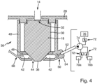
- the dispenser attachment 38 enables various additional functions (see Figure 4 ).
- the dispenser housing 40 can be designed in such a way that an additional access 68 is provided into the fluid chamber 42.
- a light guide (not shown in detail) can be guided through the additional access 68, by means of which light can be introduced into the fluid space 42, for example in order to illuminate the area in front of the end lens 36.
- compressed gas or other fluids are introduced into the fluid space 42 through the additional access 68, as described above.
- lithography fluids 22 can be provided for this purpose in separate fluid reservoirs 70a, 70b. Via corresponding switching valves 72, fluid can then be selectively conveyed from the reservoir 70a or 70b (for example by means of a fluid pump 74) through the fluid line 52 into the fluid chamber 42.
- a developer fluid or a cleaning fluid is provided in at least one further reservoir 76, which in turn can be selectively supplied to the fluid chamber 42 via a switching valve 72 and possibly via a fluid pump 74.
Landscapes
- Chemical & Material Sciences (AREA)
- Physics & Mathematics (AREA)
- Engineering & Computer Science (AREA)
- Materials Engineering (AREA)
- Optics & Photonics (AREA)
- Manufacturing & Machinery (AREA)
- Mechanical Engineering (AREA)
- General Physics & Mathematics (AREA)
- Analytical Chemistry (AREA)
- Health & Medical Sciences (AREA)
- Toxicology (AREA)
- Oil, Petroleum & Natural Gas (AREA)
- Plasma & Fusion (AREA)
- Environmental & Geological Engineering (AREA)
- Exposure And Positioning Against Photoresist Photosensitive Materials (AREA)
Claims (15)
- Utilisation d'un adaptateur de distributeur (38), en particulier d'un adaptateur de distributeur (38) pour des objectifs de microscopie, dans un dispositif (10) d'écriture de structures tridimensionnelles au moyen de lithographie laser dans un fluide de lithographie (22) qui peut être solidifié par irradiation avec de la lumière laser,le dispositif (10) comprenant:- une source de faisceau laser (12) pour émettre un faisceau d'écriture (14);- un substrat (24) pour recevoir du fluide de lithographie (22),- un objectif (18) pour former une zone de focalisation (20) du faisceau d'écriture (14) dans le fluide de lithographie (22), l'objectif (18) comprenant un boîtier d'objectif (30) et une lentille terminale (36) ;ledit adaptateur de distributeur (38) comprenant:- un boîtier de distributeur (40) qui est conçu pour être placé sur l'objectif (18) de telle sorte qu'un espace de fluide (42) est formé entre le boîtier d'objectif (30) et le boîtier de distributeur (40) et qu'une fente de sortie (44) est formée entre le boîtier de distributeur (40) et la lentille terminale (36),- et un accès de fluide (50) dans ledit espace de fluide (42);dans lequel pour l'utilisation sont réalisées les étapes suivantes consistant à:- fournir un fluide de lithographie (22) qui est adapté à la source de faisceau laser (12) de telle sorte que la solidification a lieu uniquement dans la zone de focalisation (20) et en utilisant un processus multiphotonique;- amener le fluide de lithographie (22) par l'accès de fluide (50) dans l'espace de fluide (42);- appliquer un volume de fluide de lithographie (22) par la fente de sortie (44);- introduire le faisceau d'écriture (14) par l'objectif (18) dans le volume de fluide de lithographie (22) et solidifier localement le fluide de lithographie (22) dans la zone de focalisation (20) par un processus multiphotonique d'écriture de la structure tridimensionnelle.
- Utilisation selon la revendication 1, dans laquelle l'étape d'application se fait de telle sorte que le fluide de lithographie (22) reste en contact avec la lentille terminale (36) et le faisceau d'écriture (14) est introduit dans le fluide de lithographie (22) tandis que le fluide de lithographie (22) est en contact avec la lentille terminale (36).
- Utilisation selon la revendication 1 ou 2, dans laquelle l'étape d'application se fait de telle sorte que le fluide de lithographie (22) reste en contact avec le substrat (24) d'une part et avec la lentille terminale (36) d'autre part.
- Utilisation selon l'une quelconque des revendications précédentes, dans laquelle un premier fluide de lithographie (22) est fourni, est amené par l'accès de fluide (50) dans l'espace de fluide (42), et un premier volume du premier fluide de lithographie (22) est appliqué par la fente de sortie (44),
et dans lequel un deuxième fluide de lithographie (22) est ensuite fourni, est amené par l'accès de fluide (50) dans l'espace de fluide (42) et un deuxième volume du deuxième fluide de lithographie (22) est appliqué par la fente de sortie (44). - Utilisation selon la revendication 4, dans laquelle le premier fluide de lithographie (22) et le deuxième fluide de lithographie (22) sont des matériaux différents ayant des propriétés matérielles différentes.
- Utilisation selon la revendication 4 ou 5, dans laquelle, après avoir appliqué le premier fluide de lithographie (22) et avant d'appliquer le deuxième fluide de lithographie (22), au moins une étape consistant à introduire le faisceau d'écriture (14) dans le volume de premier fluide de lithographie (22) et une solidification locale du premier fluide de lithographie (22) ont lieu.
- Utilisation selon la revendication 4 ou 5, dans laquelle d'abord le premier fluide de lithographie (22) est appliqué et puis le deuxième fluide de lithographie (22) est appliqué, et ensuite le premier fluide de lithographie et le deuxième fluide de lithographie sont mélangés.
- Utilisation selon l'une quelconque des revendications précédentes, dans laquelle après l'étape d'introduction du faisceau d'écriture (14) et de solidification locale du fluide de lithographie (22), les étapes suivantes sont mises en oeuvre:- fournir un fluide révélateur pour exposer et/ou durcir la structure tridimensionnelle écrite;- amener le fluide révélateur par l'accès de fluide (50) dans l'espace de fluide (42);- appliquer un volume de fluide révélateur par la fente de sortie.
- Utilisation selon l'une quelconque des revendications précédentes, comprenant l'étape suivante consistant à:- fournir et amener du gaz comprimé par l'accès de fluide (50) ou par un accès supplémentaire (68) dans l'espace de fluide (42).
- Utilisation selon l'une quelconque des revendications précédentes, comprenant l'étape suivante consistant à:- fournir un fluide de nettoyage qui est conçu pour dissoudre du fluide de lithographie (22) non solidifié et solidifié;- amener le fluide de nettoyage par l'accès de fluide (50) ou par un accès supplémentaire (68) dans l'espace de fluide (42);- évacuer du liquide de nettoyage par la fente de sortie (44).
- Utilisation selon l'une quelconque des revendications précédentes, comprenant l'étape suivante consistant à:- introduire de la lumière dans l'espace de fluide (42), en particulier au moyen d'un guide de lumière débouchant dans l'espace de fluide (42).
- Utilisation selon l'une quelconque des revendications précédentes, dans laquelle un objectif à immersion est utilisée comme objectif (18).
- Utilisation selon l'une quelconque des revendications précédentes, caractérisé par le fait que le boîtier de distributeur (40) est conçu de telle sorte que la fente de sortie (44) est une fente annulaire autour de la lentille terminale (36), dans laquelle la fente annulaire est délimitée par un bord périphérique (58) du boîtier de distributeur (40) de telle sorte que la lentille terminale (36) dépasse du boîtier du distributeur (40).
- Utilisation selon l'une quelconque des revendications 1 à 12, caractérisée par le fait que le boîtier de distributeur (40) présente une paroi intérieure (60) et une paroi extérieure (62) entourant la paroi intérieure (60) de sorte que la paroi intérieure (60) montre en direction du boîtier d'objectif (30), et que ledit espace de fluide (42) est formé entre la paroi intérieure (60) et la paroi extérieure (62), et que la paroi intérieure (60) présente une fenêtre de transmission (64) constituée d'un matériau étanche aux fluides et optiquement transparent, qui montre en direction de la lentille terminale (36), dans laquelle la fente de sortie (44) est formée entre la fenêtre de transmission (64) et la paroi extérieure (62).
- Utilisation selon l'une quelconque des revendications précédentes, caractérisée par le fait que le boîtier de distributeur (40) présente au moins un accès supplémentaire (68) dans l'espace de fluide (42), dans laquelle l'accès supplémentaire (68) est conçu pour amener des fluides ou de la lumière dans l'espace de fluide (42).
Applications Claiming Priority (1)
| Application Number | Priority Date | Filing Date | Title |
|---|---|---|---|
| DE102018128418.7A DE102018128418B3 (de) | 2018-11-13 | 2018-11-13 | Verwendung eines Dispenser-Aufsatzes und Dispenser-Aufsatz für eine Vorrichtung zum Schreiben von 3D-Strukturen mittels Laserlithografie |
Publications (3)
| Publication Number | Publication Date |
|---|---|
| EP3653363A1 EP3653363A1 (fr) | 2020-05-20 |
| EP3653363C0 EP3653363C0 (fr) | 2024-09-04 |
| EP3653363B1 true EP3653363B1 (fr) | 2024-09-04 |
Family
ID=68280722
Family Applications (1)
| Application Number | Title | Priority Date | Filing Date |
|---|---|---|---|
| EP19202490.9A Active EP3653363B1 (fr) | 2018-11-13 | 2019-10-10 | Utilisation d'un adaptateur de distribution pour un dispositif d'écriture de structures tridimensionnelles par lithographie laser |
Country Status (5)
| Country | Link |
|---|---|
| US (1) | US20200147865A1 (fr) |
| EP (1) | EP3653363B1 (fr) |
| JP (1) | JP2020078927A (fr) |
| CN (1) | CN111175955B (fr) |
| DE (1) | DE102018128418B3 (fr) |
Families Citing this family (5)
| Publication number | Priority date | Publication date | Assignee | Title |
|---|---|---|---|---|
| DE102020111715A1 (de) * | 2020-04-29 | 2021-11-04 | Carl Zeiss Microscopy Gmbh | Immersionsobjektiv und verfahren zur immersionsmikroskopie |
| US11694031B2 (en) * | 2020-11-30 | 2023-07-04 | International Business Machines Corporation | Identifying routine communication content |
| DE102022129094B4 (de) * | 2022-11-03 | 2024-06-27 | push4impact GmbH | Mikroskopobjektiv sowie Objektivrevolver und Mikroskop umfassend ein solches Mikroskopobjektiv |
| DE102023104751A1 (de) * | 2023-02-27 | 2024-08-29 | Nanoscribe Holding Gmbh | Laserlithografie-Vorrichtung und Verfahren zum Erzeugen einer dreidimensionalen Struktur |
| WO2025141307A1 (fr) | 2023-12-28 | 2025-07-03 | Vital3D Technologies | Micro-impression 3d multi-matériaux dans un écoulement laminaire |
Citations (2)
| Publication number | Priority date | Publication date | Assignee | Title |
|---|---|---|---|---|
| US20100027109A1 (en) * | 2006-09-07 | 2010-02-04 | Leica Microsystems Cms Gmbh | Immersion objective, apparatus for forming an immersion film and method |
| US20120218535A1 (en) * | 2011-02-25 | 2012-08-30 | Nanoscribe Gmbh | Method and device for a spatially resolved introduction of an intensity pattern comprising electro-magnetic radiation into a photosensitive substance as well as applications thereof |
Family Cites Families (14)
| Publication number | Priority date | Publication date | Assignee | Title |
|---|---|---|---|---|
| US3837731A (en) | 1973-06-22 | 1974-09-24 | Corning Glass Works | Oil dispenser for microscope objective |
| CA2326322C (fr) * | 1998-04-21 | 2011-03-01 | University Of Connecticut | Nanofabrication a structure libre utilisant une excitation multiphotonique |
| DE10111422A1 (de) | 2001-03-09 | 2002-09-26 | Hannover Laser Zentrum | Verfahren und Vorrichtung zur Herstellung eines Formkörpers aus einem durch Bestrahlung zu verfestigenden flüssigen Material |
| EP1524558A1 (fr) * | 2003-10-15 | 2005-04-20 | ASML Netherlands B.V. | Appareil lithographique et procédé pour la production d'un dispositif |
| JP4253592B2 (ja) * | 2004-01-06 | 2009-04-15 | オリンパス株式会社 | 液浸対物レンズ、蛍光分析装置および倒立型顕微鏡。 |
| US8339572B2 (en) * | 2008-01-25 | 2012-12-25 | Asml Netherlands B.V. | Lithographic apparatus and device manufacturing method |
| NL2005610A (en) * | 2009-12-02 | 2011-06-06 | Asml Netherlands Bv | Lithographic apparatus and surface cleaning method. |
| DE102010020158A1 (de) * | 2010-05-11 | 2011-11-17 | Fraunhofer-Gesellschaft zur Förderung der angewandten Forschung e.V. | Vorrichtung sowie Verfahren zur Erzeugung dreidimensionaler Strukturen |
| WO2014138503A1 (fr) * | 2013-03-06 | 2014-09-12 | Roller Bearing Company Of America, Inc. | Appareil de couplage avec une tête asymétrique à faible encombrement |
| DE102013107297B4 (de) * | 2013-07-10 | 2025-04-24 | Carl Zeiss Microscopy Gmbh | Anordnung zur Lichtblattmikroskopie |
| DE102013011544A1 (de) * | 2013-07-11 | 2015-01-15 | Carl Zeiss Microscopy Gmbh | Vorrichtung zum Ausbilden eines Immersionfilmes |
| CN105793758A (zh) * | 2013-12-06 | 2016-07-20 | 3M创新有限公司 | 具有保护元件的半潜式显微镜物镜和物镜在多光子成像方法中的用途 |
| JP6775760B2 (ja) * | 2015-07-06 | 2020-10-28 | 株式会社リコー | 立体造形用液体セット、立体造形物の製造方法、立体造形物の製造装置、及びハイドロゲル造形体 |
| EP3287263A1 (fr) * | 2016-08-26 | 2018-02-28 | Multiphoton Optics Gmbh | Dispositif et procede de traitement par laser de corps ou de surfaces |
-
2018
- 2018-11-13 DE DE102018128418.7A patent/DE102018128418B3/de active Active
-
2019
- 2019-10-10 EP EP19202490.9A patent/EP3653363B1/fr active Active
- 2019-10-29 US US16/667,803 patent/US20200147865A1/en not_active Abandoned
- 2019-11-01 JP JP2019199611A patent/JP2020078927A/ja active Pending
- 2019-11-12 CN CN201911098492.1A patent/CN111175955B/zh active Active
Patent Citations (2)
| Publication number | Priority date | Publication date | Assignee | Title |
|---|---|---|---|---|
| US20100027109A1 (en) * | 2006-09-07 | 2010-02-04 | Leica Microsystems Cms Gmbh | Immersion objective, apparatus for forming an immersion film and method |
| US20120218535A1 (en) * | 2011-02-25 | 2012-08-30 | Nanoscribe Gmbh | Method and device for a spatially resolved introduction of an intensity pattern comprising electro-magnetic radiation into a photosensitive substance as well as applications thereof |
Also Published As
| Publication number | Publication date |
|---|---|
| EP3653363C0 (fr) | 2024-09-04 |
| DE102018128418B3 (de) | 2019-11-14 |
| CN111175955A (zh) | 2020-05-19 |
| CN111175955B (zh) | 2022-12-20 |
| EP3653363A1 (fr) | 2020-05-20 |
| US20200147865A1 (en) | 2020-05-14 |
| JP2020078927A (ja) | 2020-05-28 |
Similar Documents
| Publication | Publication Date | Title |
|---|---|---|
| EP3653363B1 (fr) | Utilisation d'un adaptateur de distribution pour un dispositif d'écriture de structures tridimensionnelles par lithographie laser | |
| DE102011012484B4 (de) | Verfahren und Vorrichtung zum ortsaufgelösten Einbringen eines Intensitätsmusters aus elektromagnetischer Strahlung in eine photosensitive Substanz sowie Verwendung hiervon | |
| DE102013215040B4 (de) | Kompakte Vorrichtung zur Herstellung eines dreidimensionalen Objekts durch Verfestigen eines fotohärtenden Materials | |
| DE102015012980B4 (de) | Verfahren zur Herstellung von Mikrostrukturen auf optischen Fasern | |
| DE4018135B4 (de) | Verfahren und Vorrichtung zur Reparatur von Fehlern in Emulsionsmasken | |
| EP4032688A1 (fr) | Procédé et dispositif de fabrication d'un objet tridimensionnel dans une matière de base optiquement réactive | |
| DD221563A1 (de) | Immersionsobjektiv fuer die schrittweise projektionsabbildung einer maskenstruktur | |
| DE202013103446U1 (de) | Kompakte Vorrichtung zur Herstellung eines dreidimensionalen Objekts durch Verfestigen eines fotohärtenden Materials | |
| EP3494440A1 (fr) | Procédé et dispositif de génération lithographique d'une structure cible sur une structure initiale non plane | |
| DE10297658T5 (de) | Verfahren und System zum Reparieren defekter Photomasken | |
| DE102014220168B4 (de) | Optisches System zur lithografischen Strukturerzeugung und Verfahren zur Bestimmung von Relativkoordinaten | |
| EP3162549A1 (fr) | Procede et dispositif de fabrication d'un element optique ayant au moins une zone fonctionnelle, et utilisation du dispositif | |
| WO2020249171A1 (fr) | Dispositif pour traiter ou inspecter un matériau, utilisation du dispositif | |
| EP3894928B1 (fr) | Dispositif et procédé pour le traitement optique d'un objet | |
| DE102024116622A1 (de) | Bauteil mit einer in einem Bauteilmaterial ausgebildeten Hohlstruktur zum Führen von Fluiden | |
| DE202014011053U1 (de) | Lithografieeinrichtung zum Herstellen einer Struktur | |
| WO2024038126A1 (fr) | Dispositif de reproduction pour reproduire des hologrammes dans des photopolymères liquides | |
| DE102006043548A1 (de) | Optische Messvorrichtung | |
| DE102011123139B4 (de) | Verfahren und Vorrichtung zum ortsaufgelösten Einbringen eines Intensitätsmusters aus elektromagnetischer Strahlung in eine photosensitive Substanz sowie Verwendung hiervon | |
| EP4420859A1 (fr) | Dispositif de lithographie laser et procédé de génération d'une structure tridimensionnelle | |
| DE102016218744A1 (de) | Projektionsbelichtungsanlage mit Flüssigkeitsschicht zur Wellenfrontkorrektur | |
| DE102020132417B4 (de) | Verfahren und Vorrichtung zur Herstellung von mikroskopischen dreidimensionalen Multimaterialstrukturen | |
| DE202013105209U1 (de) | Auffüll-Apparatur für Immersionsflüssigkeiten und Inspektionsmaschine für Wafer-Ritz-Linien mit Auffüll-Apparatur für Immersionsflüssigkeiten | |
| AT520718A4 (de) | Verfahren zur herstellung eines formeinsatzes mit (sub-)mikrostrukturen sowie werkstück mit (sub-)mikrostrukturen | |
| DE102009033823A1 (de) | Verfahren zur Immersionslithographie und Vorrichtung zur Durchführung des Verfahrens |
Legal Events
| Date | Code | Title | Description |
|---|---|---|---|
| PUAI | Public reference made under article 153(3) epc to a published international application that has entered the european phase |
Free format text: ORIGINAL CODE: 0009012 |
|
| STAA | Information on the status of an ep patent application or granted ep patent |
Free format text: STATUS: THE APPLICATION HAS BEEN PUBLISHED |
|
| AK | Designated contracting states |
Kind code of ref document: A1 Designated state(s): AL AT BE BG CH CY CZ DE DK EE ES FI FR GB GR HR HU IE IS IT LI LT LU LV MC MK MT NL NO PL PT RO RS SE SI SK SM TR |
|
| AX | Request for extension of the european patent |
Extension state: BA ME |
|
| STAA | Information on the status of an ep patent application or granted ep patent |
Free format text: STATUS: REQUEST FOR EXAMINATION WAS MADE |
|
| 17P | Request for examination filed |
Effective date: 20201106 |
|
| RBV | Designated contracting states (corrected) |
Designated state(s): AL AT BE BG CH CY CZ DE DK EE ES FI FR GB GR HR HU IE IS IT LI LT LU LV MC MK MT NL NO PL PT RO RS SE SI SK SM TR |
|
| RAP3 | Party data changed (applicant data changed or rights of an application transferred) |
Owner name: NANOSCRIBE HOLDING GMBH |
|
| STAA | Information on the status of an ep patent application or granted ep patent |
Free format text: STATUS: EXAMINATION IS IN PROGRESS |
|
| 17Q | First examination report despatched |
Effective date: 20220217 |
|
| GRAP | Despatch of communication of intention to grant a patent |
Free format text: ORIGINAL CODE: EPIDOSNIGR1 |
|
| STAA | Information on the status of an ep patent application or granted ep patent |
Free format text: STATUS: GRANT OF PATENT IS INTENDED |
|
| INTG | Intention to grant announced |
Effective date: 20240422 |
|
| GRAS | Grant fee paid |
Free format text: ORIGINAL CODE: EPIDOSNIGR3 |
|
| GRAA | (expected) grant |
Free format text: ORIGINAL CODE: 0009210 |
|
| STAA | Information on the status of an ep patent application or granted ep patent |
Free format text: STATUS: THE PATENT HAS BEEN GRANTED |
|
| AK | Designated contracting states |
Kind code of ref document: B1 Designated state(s): AL AT BE BG CH CY CZ DE DK EE ES FI FR GB GR HR HU IE IS IT LI LT LU LV MC MK MT NL NO PL PT RO RS SE SI SK SM TR |
|
| REG | Reference to a national code |
Ref country code: GB Ref legal event code: FG4D Free format text: NOT ENGLISH |
|
| REG | Reference to a national code |
Ref country code: CH Ref legal event code: EP |
|
| REG | Reference to a national code |
Ref country code: IE Ref legal event code: FG4D Free format text: LANGUAGE OF EP DOCUMENT: GERMAN |
|
| REG | Reference to a national code |
Ref country code: DE Ref legal event code: R096 Ref document number: 502019012031 Country of ref document: DE |
|
| U01 | Request for unitary effect filed |
Effective date: 20240913 |
|
| U07 | Unitary effect registered |
Designated state(s): AT BE BG DE DK EE FI FR IT LT LU LV MT NL PT RO SE SI Effective date: 20241009 |
|
| U20 | Renewal fee for the european patent with unitary effect paid |
Year of fee payment: 6 Effective date: 20241022 |
|
| PG25 | Lapsed in a contracting state [announced via postgrant information from national office to epo] |
Ref country code: NO Free format text: LAPSE BECAUSE OF FAILURE TO SUBMIT A TRANSLATION OF THE DESCRIPTION OR TO PAY THE FEE WITHIN THE PRESCRIBED TIME-LIMIT Effective date: 20241204 |
|
| PG25 | Lapsed in a contracting state [announced via postgrant information from national office to epo] |
Ref country code: PL Free format text: LAPSE BECAUSE OF FAILURE TO SUBMIT A TRANSLATION OF THE DESCRIPTION OR TO PAY THE FEE WITHIN THE PRESCRIBED TIME-LIMIT Effective date: 20240904 Ref country code: GR Free format text: LAPSE BECAUSE OF FAILURE TO SUBMIT A TRANSLATION OF THE DESCRIPTION OR TO PAY THE FEE WITHIN THE PRESCRIBED TIME-LIMIT Effective date: 20241205 |
|
| PG25 | Lapsed in a contracting state [announced via postgrant information from national office to epo] |
Ref country code: HR Free format text: LAPSE BECAUSE OF FAILURE TO SUBMIT A TRANSLATION OF THE DESCRIPTION OR TO PAY THE FEE WITHIN THE PRESCRIBED TIME-LIMIT Effective date: 20240904 |
|
| PG25 | Lapsed in a contracting state [announced via postgrant information from national office to epo] |
Ref country code: ES Free format text: LAPSE BECAUSE OF FAILURE TO SUBMIT A TRANSLATION OF THE DESCRIPTION OR TO PAY THE FEE WITHIN THE PRESCRIBED TIME-LIMIT Effective date: 20240904 Ref country code: RS Free format text: LAPSE BECAUSE OF FAILURE TO SUBMIT A TRANSLATION OF THE DESCRIPTION OR TO PAY THE FEE WITHIN THE PRESCRIBED TIME-LIMIT Effective date: 20241204 |
|
| PG25 | Lapsed in a contracting state [announced via postgrant information from national office to epo] |
Ref country code: RS Free format text: LAPSE BECAUSE OF FAILURE TO SUBMIT A TRANSLATION OF THE DESCRIPTION OR TO PAY THE FEE WITHIN THE PRESCRIBED TIME-LIMIT Effective date: 20241204 Ref country code: PL Free format text: LAPSE BECAUSE OF FAILURE TO SUBMIT A TRANSLATION OF THE DESCRIPTION OR TO PAY THE FEE WITHIN THE PRESCRIBED TIME-LIMIT Effective date: 20240904 Ref country code: NO Free format text: LAPSE BECAUSE OF FAILURE TO SUBMIT A TRANSLATION OF THE DESCRIPTION OR TO PAY THE FEE WITHIN THE PRESCRIBED TIME-LIMIT Effective date: 20241204 Ref country code: HR Free format text: LAPSE BECAUSE OF FAILURE TO SUBMIT A TRANSLATION OF THE DESCRIPTION OR TO PAY THE FEE WITHIN THE PRESCRIBED TIME-LIMIT Effective date: 20240904 Ref country code: GR Free format text: LAPSE BECAUSE OF FAILURE TO SUBMIT A TRANSLATION OF THE DESCRIPTION OR TO PAY THE FEE WITHIN THE PRESCRIBED TIME-LIMIT Effective date: 20241205 Ref country code: ES Free format text: LAPSE BECAUSE OF FAILURE TO SUBMIT A TRANSLATION OF THE DESCRIPTION OR TO PAY THE FEE WITHIN THE PRESCRIBED TIME-LIMIT Effective date: 20240904 |
|
| PG25 | Lapsed in a contracting state [announced via postgrant information from national office to epo] |
Ref country code: IS Free format text: LAPSE BECAUSE OF FAILURE TO SUBMIT A TRANSLATION OF THE DESCRIPTION OR TO PAY THE FEE WITHIN THE PRESCRIBED TIME-LIMIT Effective date: 20250104 |
|
| PG25 | Lapsed in a contracting state [announced via postgrant information from national office to epo] |
Ref country code: SM Free format text: LAPSE BECAUSE OF FAILURE TO SUBMIT A TRANSLATION OF THE DESCRIPTION OR TO PAY THE FEE WITHIN THE PRESCRIBED TIME-LIMIT Effective date: 20240904 |
|
| PG25 | Lapsed in a contracting state [announced via postgrant information from national office to epo] |
Ref country code: CZ Free format text: LAPSE BECAUSE OF FAILURE TO SUBMIT A TRANSLATION OF THE DESCRIPTION OR TO PAY THE FEE WITHIN THE PRESCRIBED TIME-LIMIT Effective date: 20240904 |
|
| PG25 | Lapsed in a contracting state [announced via postgrant information from national office to epo] |
Ref country code: SK Free format text: LAPSE BECAUSE OF FAILURE TO SUBMIT A TRANSLATION OF THE DESCRIPTION OR TO PAY THE FEE WITHIN THE PRESCRIBED TIME-LIMIT Effective date: 20240904 |
|
| REG | Reference to a national code |
Ref country code: CH Ref legal event code: PL |
|
| PG25 | Lapsed in a contracting state [announced via postgrant information from national office to epo] |
Ref country code: MC Free format text: LAPSE BECAUSE OF FAILURE TO SUBMIT A TRANSLATION OF THE DESCRIPTION OR TO PAY THE FEE WITHIN THE PRESCRIBED TIME-LIMIT Effective date: 20240904 |
|
| PLBE | No opposition filed within time limit |
Free format text: ORIGINAL CODE: 0009261 |
|
| STAA | Information on the status of an ep patent application or granted ep patent |
Free format text: STATUS: NO OPPOSITION FILED WITHIN TIME LIMIT |
|
| PG25 | Lapsed in a contracting state [announced via postgrant information from national office to epo] |
Ref country code: CH Free format text: LAPSE BECAUSE OF NON-PAYMENT OF DUE FEES Effective date: 20241031 |
|
| 26N | No opposition filed |
Effective date: 20250605 |
|
| GBPC | Gb: european patent ceased through non-payment of renewal fee |
Effective date: 20241204 |
|
| PG25 | Lapsed in a contracting state [announced via postgrant information from national office to epo] |
Ref country code: GB Free format text: LAPSE BECAUSE OF NON-PAYMENT OF DUE FEES Effective date: 20241204 |
|
| PG25 | Lapsed in a contracting state [announced via postgrant information from national office to epo] |
Ref country code: IE Free format text: LAPSE BECAUSE OF NON-PAYMENT OF DUE FEES Effective date: 20241010 |
|
| U20 | Renewal fee for the european patent with unitary effect paid |
Year of fee payment: 7 Effective date: 20251027 |
|
| PG25 | Lapsed in a contracting state [announced via postgrant information from national office to epo] |
Ref country code: CY Free format text: LAPSE BECAUSE OF FAILURE TO SUBMIT A TRANSLATION OF THE DESCRIPTION OR TO PAY THE FEE WITHIN THE PRESCRIBED TIME-LIMIT; INVALID AB INITIO Effective date: 20191010 |
|
| PG25 | Lapsed in a contracting state [announced via postgrant information from national office to epo] |
Ref country code: HU Free format text: LAPSE BECAUSE OF FAILURE TO SUBMIT A TRANSLATION OF THE DESCRIPTION OR TO PAY THE FEE WITHIN THE PRESCRIBED TIME-LIMIT; INVALID AB INITIO Effective date: 20191010 |