EP3653444B1 - Support de pied de porteur de charge - Google Patents
Support de pied de porteur de charge Download PDFInfo
- Publication number
- EP3653444B1 EP3653444B1 EP19209222.9A EP19209222A EP3653444B1 EP 3653444 B1 EP3653444 B1 EP 3653444B1 EP 19209222 A EP19209222 A EP 19209222A EP 3653444 B1 EP3653444 B1 EP 3653444B1
- Authority
- EP
- European Patent Office
- Prior art keywords
- load carrier
- holder
- carrier bracket
- bracket
- trough
- Prior art date
- Legal status (The legal status is an assumption and is not a legal conclusion. Google has not performed a legal analysis and makes no representation as to the accuracy of the status listed.)
- Active
Links
Images






Classifications
-
- B—PERFORMING OPERATIONS; TRANSPORTING
- B60—VEHICLES IN GENERAL
- B60R—VEHICLES, VEHICLE FITTINGS, OR VEHICLE PARTS, NOT OTHERWISE PROVIDED FOR
- B60R9/00—Supplementary fittings on vehicle exterior for carrying loads, e.g. luggage, sports gear or the like
- B60R9/04—Carriers associated with vehicle roof
- B60R9/058—Carriers associated with vehicle roof characterised by releasable attaching means between carrier and roof
Definitions
- a load carrier foot for supporting a load bar on a vehicle comprises a holder adapted to receive a load carrier bracket for coupling the load carrier foot to the vehicle.
- the holder comprises a sleeve portion defining an accommodating space which is configured to partially accommodate the load carrier bracket.
- the sleeve portion creates a 3D structure that better withstands forces acting on the system. Since the holder comprises a sleeve portion, the overall strength of the bracket is enhanced. Thus, the holder is able to withstand higher forces. Therefore, the holder can be used for transferring higher forces on other elements like the load carrier bracket. In this way, it is possible to transfer all forces necessary for tightening the load carrier bracket via the holder.
- the sleeve portion can comprise a box-like shape and can comprise an outer wall, an inner wall and two side walls.
- the strength of the holder can be increased without using additional components.
- the sleeve portion comprises a coupling portion formed in the inner wall.
- the coupling portion can be formed as an accommodating recess configured to support a tightening member for applying a pushing force on the coupling portion.
- the accommodating recess can comprise a supporting surface.
- the supporting surface can be a curved surface.
- the accommodating recess can comprise an opening for passing a portion of the tightening member through the inner wall.
- the supporting surface can be configured to directly support the tightening member. It is also possible to indirectly support the tightening member on the supporting surface using an intermediate member.
- the locking mechanism can be configured to clamp the load bar on a supporting portion of the load carrier foot, which can be a portion of the rear cover.
- the supporting portion can be an integral part of the rear cover of the load carrier foot.
- the rear cover can also be referred to as support member for supporting the load bar thereon.
- the supporting portion can comprise a supporting surface formed in the rear cover. Accordingly, the rear cover can acts as a support for supporting the load bar.
- the load bar can be supported on an upper portion of the rear cover.
- the rear cover can be supported on the foot pad. More precisely, the rear cover can comprise a coupling portion which is engaged with the foot pad.
- the foot pad can be adapted to contact the vehicle roof and for transferring a load onto the vehicle roof.
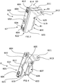
- the holder 6 comprises a sleeve portion 600 which is formed in a lower portion 67 of the holder 6.
- the sleeve portion 600 comprises a box-like shape and comprises an outer wall 602, an inner wall 603 and two side walls 605 connecting the inner wall 603 with the outer wall 602.
- the holder 6 is integrally formed by bending a metal sheet into the described shape.
- the outer wall 602 is defined by an overlap section 601 which is formed by two joining sections 612, 614 of the metal sheet.
- the joining sections 612, 614 are arranged parallel and in contact with each other. More precisely, the joining sections 612, 614 are joined with each other by press-forming them together. In the present case, the joining sections 612, 614 are clinched together at four joining portions 604. Accordingly, the outer wall 602 is reinforced by using two layers of sheet metal that are joined to each other. As is visible in Figs. 9 and 13 , the joining sections 612, 614, which can also be referred to as overlapping flanges, can extend across the entire width of the holder.
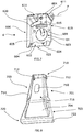
- the outer wall 602 comprises an access opening 650 providing access to the accommodating space 630 from a front side of the load carrier foot 2.
- This access opening 650 is designed such that a tool for operating the tightening member 8 can be inserted into the accommodating space 630.
- the holder 6 comprises an upper portion 63 which comprises a coupling portion 64.
- the coupling portion 64 comprises two arms 611 each having an opening 613 for accommodating a pivot pin 610 therein.
- the pivot pin 610 is shown in Fig. 12 and defines a pivot axis P.
- the pivot axis P extends through the centers of the openings 613.
- the holder 6 is configured for a pivoting movement about pivot axis P.
- the holder 6 comprises a coupling section 61 for supporting the tightening member 8.
- the tightening member 8 is an element which transfers a pushing force on the coupling portion 61 upon operation of the same.
- the coupling portion 61 comprises an accommodating recess 607 which is formed in the inner wall 603.
- the accommodating recess 607 comprises a supporting surface 608 which is formed in a spherical manner.
- An opening 609 is provided in the supporting surface 608 allowing to pass a portion of the tightening member through the inner wall 603.
- the opening is an elongate opening extending along the longitudinal direction of the sleeve portion 600.
- the elongate opening can have an extension length allowing to insert the tightening member via the lower opening 622.
- the urging member 640 is configured to apply an urging force on an inserted load carrier bracket 700 in order to urge the load carrier bracket towards the inner wall 603.
- the urging member can be made from plastics and can be integrally formed with the intermediate member 642 as described before.
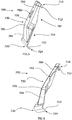
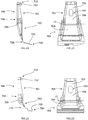
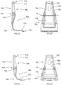
- the load carrier bracket 700 comprises a vehicle engaging section 720 and a trough-shaped coupling portion 730.
- the vehicle engaging section 720 is configured to securely grab a portion of a vehicle body.
- the vehicle engaging portion 720 is specifically designed so as to fit to a specific vehicle body.
- the vehicle engaging section 720 is a bent or angled portion which is coupled to the trough-shaped coupling portion 730 at one end.
- the vehicle engaging section 720 comprises a free end 724 which protrudes in a direction which is angled with respect to or substantially perpendicular to a longitudinal extension direction of the trough-shaped coupling portion 730.
- a contact surface 722 is provided which, when the load carrier foot is clamped on the vehicle roof, is pushed against the vehicle body.
- the vehicle engaging section 720 is configured, such that the free end 724 can be inserted into a suitable space provided on the vehicle, a space between a closed vehicle door and the vehicle body for instance.
- the trough-shaped coupling portion 730 extends from the vehicle engaging section 720 in the longitudinal direction of the load carrier bracket 700. Furthermore, the trough-shaped coupling portion 730 comprises a holder engaging portion 710 which is engageable with the holder 6 of a load carrier foot 2. The trough-shaped coupling portion 730 is funnel-shaped wherein the holder engaging portion 710 is formed at an narrow end of the trough-shaped coupling portion 730.
- the load carrier bracket can be formed symmetrical with respect to a middle plane at least in sections. Since the load carrier bracket has to fit to different types of vehicles, it is necessary to form the vehicle engaging section 720 according to the vehicle body of the vehicle. Accordingly, a lower portion 703 of the load carrier bracket 700 has to be formed corresponding to the vehicle body type. On the other hand, the configuration of the load carrier foot 700 remains the same for different vehicles at least regarding the fixation and engagement of the load carrier bracket 700. Therefore, an upper portion 701 of the load carrier bracket 700 which is inserted into the holder 6 can always be formed in the same manner. In practice, it turned out that the section-wise forming of the load carrier bracket 700, i.e. the separate forming of the upper portion 701 and the lower portion 703, is cost efficient as it allows the use of one and the same tool for forming the upper portion 701. In this way, only a respective specific smaller tool have to be provided for forming the lower portion 703.
- the trough-shaped coupling portion 730 extends substantially over the entire length of the bracket 700 and is uninterrupted. In other words, only a single trough-shaped coupling portion is provided. Furthermore, the trough-shaped coupling portion 730 at least partially comprises a box-like shape. More precisely, the trough-shaped coupling portion 730 comprises two side walls 714 and a bottom wall 716 which is arranged substantially perpendicular to the side walls 714. The bottom wall 716 and, consequently, the outer surface 702 is convexly shaped giving the overall load carrier bracket 700 a convex shape when viewed from the side. In other words, the trough-shaped coupling portion 730 provides a bulging in only one direction.
- the bulging is provided on a side of the load carrier bracket 700 opposite to the side where the free end 724 of the vehicle engaging section 720 is provided.
- the bottom wall 716 comprises a curved section 705 arranged between two substantially flat sections 704, 706 so that the overall configuration is curved in only one direction. In other words, the bottom wall 716 does not comprise a portion which is curved in the opposite direction.
- the holder engaging section 710 is configured such that the load carrier bracket 700 can be hooked on the holder 6.
- the holder engaging section 710 comprises two hooks 712 which are arranged at a distance to each other in lateral direction of the load carrier bracket 700.
- the hooks 712 are configured such that they can be engaged with the upper edge portion 619 of the sleeve portion 600 of the holder 6.
- the hooks 712 and the free end 724 of the vehicle engaging section 720 can be referred to as protrusions of the load carrier bracket 700 which protrude from the same side of the load carrier bracket 700.
- the hooks 712 and the free end 724 protrude towards the vehicle.
- the load carrier bracket 700 is inserted into the holder 6 such that the hooks 712 are located on the side of the inner wall 603 of the holder.
- the load carrier bracket 700 is inserted into the holder 6 from below.
- the upper portion 701 of the load carrier bracket 700 is inserted into the sleeve portion 600 through the lower opening 622 up to a position where the holder engaging portion 710 partially protrudes from the upper opening 615. More precisely, the load carrier bracket 700 is brought into a position in which the hooks 712 are located above the upper edge portion 619 so that the hooks 712 can be brought in contact with the supporting surface 620 of the upper edge portion 619.
- the holder 6 comprises the urging member 640.
- the urging member 640 comes into contact with the upper portion 701 of the load carrier bracket 700 and pushes the holder engaging portion 710 inward, i.e. towards the upper edge portion 619 so that the hooks 712 are brought into position for an engagement with the upper edge portion 619 and are held there. Accordingly, the load carrier bracket is securely held on the upper edge portion 619 and can only be removed when the load carrier bracket 700 is moved such that the holder engaging portion 710 is moved against the urging force of the urging member 640.
- the upper edge portion 619 is convexly curved and the hooks 712 are arranged at a distance with respect to each other.
- the load carrier bracket 700 is supported on the upper edge portion at two different points.
- the upper edge portion is wider than the width of the holder engaging section 710 leading to a configuration in which the hooks can slide on the surface 620.
- the upper portion 701 of the load carrier bracket 700 is formed such that the load carrier bracket is hingedly held on the upper edge portion 619. This allows a pivoting movement of the load carrier bracket 700 about the center of the curvature of the surface 620. In this way, the load carrier bracket can orient itself according to the shape of the vehicle body when the same is tightened by moving the holder 6.
- the holder 6 can be rotated about the pivot axis P in counterclockwise direction in Fig. 3 in order to tighten the load carrier bracket 700.
- the rotation of the holder 6 is effected by an operation of the tightening member 8 which is supported on the inner wall 603 of the holder 6.
- the load carrier bracket 700 is clamped between the holder 6 and the vehicle body.
- the lower edge portion 621 of the holder 6 is moved towards the vehicle when the tightening member is tightened which leads to a state in which the lower edge portion 621 contacts the outer surface 702 of the load carrier bracket 700 such that the lower edge portion 621 contacts the outer surface 702 right above the curved section 705 in order to push the load carrier bracket towards the vehicle.
- the holder 6 is held such that the pivot axis P also moves upward during the tightening process. Since the load carrier bracket 700 is supported on the upper edge portion 619 of the holder, a movement of the holder in the upward direction pulls the load carrier bracket in the upward direction so that the contact surface 722 is moved upwards and brought into firm contact with the vehicle body. Due to the shape of the holder and the shape of the bracket, it is possible to generate a higher clamping force.
- the load carrier bracket 700 comprises an access opening 750.
- the access opening 750 is provided such that when the load carrier bracket 700 is hooked into the holder 6 in the above described way, the access opening 750 is aligned with the access opening 650 of the holder 6. Since both openings are aligned, it is possible to reach the operating portion 81 of the tightening member 8 from the outside by passing a tool through the openings. Due to this configuration, it is possible to support the tightening member on the inner wall 603 of the holder 6. Furthermore, it is possible to insert the tightening member 8 into the holder 6 prior to the insertion of the load carrier bracket 700.
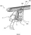
- the load carrier comprises a load bar 300 which is coupled to a load carrier foot 2.
- the load carrier foot 2 comprises the above described holder 6.
- the above described load carrier bracket 700 is inserted in the holder 6.
- the load carrier foot 2 comprises a foot pad 3 which is brought in contact with the roof of a vehicle when the load carrier is mounted.
- the holder 6 is operatively coupled with a tightening mechanism 500 of the load carrier foot 2.
- the tightening mechanism 500 is operated by the tightening member 8.
- the tightening mechanism 500 is configured to effect a movement of the holder 6 in the above described way about the pivot axis P and to operate a locking mechanism 200 for securely locking the load bar 300 to the load carrier foot 2 when the tightening member 8 is operated.
- the tightening member 8 is threadedly engaged with a pin 515 which is pivotably held in a force distribution member of the tightening mechanism 500.
- the force distribution member transfers an input force on two application sections.
- the load bar 300 is supported on an upper portion of the rear cover 4.
- the rear cover 4 is supported on the foot pad 3. More precisely, the rear cover 4 comprises a coupling portion 41 which is engaged with the foot pad 3. This coupling portion is shown in Figs. 12 and 14 .
- the foot pad 3 is adapted to contact the vehicle roof and for transferring a load onto the vehicle roof.
- the rear cover can be movably, e.g. rotatably, supported on the foot pad. More precisely, a lower portion of the rear cover can be specifically designed to be supported on an upper side of the foot pad 3.
- the rear cover 4 is able to transfer a load received from a load bar 300 onto the foot pad 3. In this way, a major part of a normal force applied on the load carrier foot 2 by the load bar 300 is directly transferred to the foot pad 3 by means of the rear cover.
- the configuration is such that the foot pad 3 only receives forces from the rear cover.
- the lower portion 703 is different in every embodiment. More precisely, the lower portion 703 is respectively adapted to fit to different vehicles.
- Example shapes of the load carrier bracket 700 i.e. specific shapes of the lower portion 703 are shown in Figs. 17 to 28 .
- the shapes vary in the lower portion 703, for example regarding the trough-shaped portion in formed in the lower portion 703 and regarding the vehicle engaging section 720. Most of the shapes follow the above general shape as described before and are convexly shaped.
- Fig. 23 a comparative example is shown in which the curved section 705 is bent in opposite direction compared to other embodiments.
Landscapes
- Engineering & Computer Science (AREA)
- Mechanical Engineering (AREA)
- Fittings On The Vehicle Exterior For Carrying Loads, And Devices For Holding Or Mounting Articles (AREA)
Claims (7)
- Patte de dispositif porte-charge (700) pour le couplage d'un pied de dispositif porte-charge (2) à un véhicule, ladite patte de dispositif porte-charge (700) comprenant une section (720) de mise en prise avec un véhicule et une partie de couplage en forme de goulotte (730), ladite partie de couplage en forme de goulotte (730) s'étendant de ladite section (720) de mise en prise avec un véhicule dans la direction longitudinale de la patte de dispositif porte-charge (700) et comprenant une section (710) de mise en prise avec un support qui est configurée pour être mise en prise de manière libérable avec un support (6) dudit pied de dispositif porte-charge (2), caractérisée en ce que ladite partie de couplage en forme de goulotte (730) est formée de façon convexe en continu dans sa direction longitudinale de telle sorte qu'il est possible d'appliquer des forces plus élevées sur une surface externe (702) de ladite partie de couplage en forme de goulotte (730).
- Patte de dispositif porte-charge (700) selon l'une des revendications précédentes, dans laquelle ladite partie de couplage en forme de goulotte (730) est en forme d'entonnoir, ladite section (710) de mise en prise avec un support étant formée au niveau d'une extrémité étroite.
- Patte de dispositif porte-charge (700) selon l'une des revendications précédentes, dans laquelle ladite partie de couplage en forme de goulotte (730) s'étend sensiblement sur toute la longueur de la patte (700) et/ou comprend au moins partiellement une forme de type boîte, avec de préférence deux parois latérales (714) et une paroi inférieure (716) qui est disposée sensiblement perpendiculairement auxdites parois latérales (714).
- Patte de dispositif porte-charge (700) selon l'une des revendications précédentes, dans laquelle une extrémité libre (724) de la section (720) de mise en prise avec un véhicule fait saillie depuis ladite patte de dispositif porte-charge (700) sur un côté dans une direction qui est inclinée par rapport à, ou est sensiblement perpendiculaire à, une direction d'extension longitudinale de la partie de couplage en forme de goulotte (730) et dans laquelle ladite partie de couplage en forme de goulotte (730) fournit un renflement qui est situé sur un côté de ladite patte de dispositif porte-charge (700) opposé au côté où ladite extrémité libre (724) de la section (720) de mise en prise avec un véhicule fait saillie depuis ladite patte de dispositif porte-charge, et/ou dans laquelle ladite partie de couplage en forme de goulotte (730) fournit ledit renflement dans une seule direction, ledit renflement étant de préférence un renflement continu et/ou ininterrompu.
- Patte de dispositif porte-charge (700) selon l'une des revendications précédentes, dans laquelle ladite section (710) de mise en prise avec un support est configurée de sorte que ladite patte de dispositif porte-charge (700) peut être accrochée sur ledit support (6) et dans laquelle ladite section (710) de mise en prise avec le support comprend de préférence deux crochets (712).
- Patte de dispositif porte-charge (700) selon la revendication 5, dans laquelle lesdits crochets (712) et une extrémité libre (724) de ladite section (720) de mise en prise avec un véhicule font saillie depuis le même côté de ladite patte de dispositif porte-charge (700) et/ou dans laquelle lesdits crochets (712) sont configurés de sorte qu'ils peuvent être mis en prise avec une partie de bord supérieur (619) d'une partie manchon (600), dans laquelle les crochets peuvent de préférence être mis en contact avec une surface de support (620) de ladite partie de bord supérieur (619).
- Patte de dispositif porte-charge (700) selon l'une des revendications 5 et 6, comprenant en outre une partie supérieure (701) pouvant être insérée dans un support dudit pied de dispositif porte-charge (6), dans laquelle ladite partie supérieure (701) est configurée pour recevoir une force de poussée pour pousser ladite partie (710) de mise en prise avec le support dans une direction pour amener lesdits crochets (712) en position pour une mise en prise avec ledit support (6).
Priority Applications (1)
| Application Number | Priority Date | Filing Date | Title |
|---|---|---|---|
| EP19209222.9A EP3653444B1 (fr) | 2017-12-19 | 2017-12-19 | Support de pied de porteur de charge |
Applications Claiming Priority (2)
| Application Number | Priority Date | Filing Date | Title |
|---|---|---|---|
| EP17208327.1A EP3501903B1 (fr) | 2017-12-19 | 2017-12-19 | Pied support de charge |
| EP19209222.9A EP3653444B1 (fr) | 2017-12-19 | 2017-12-19 | Support de pied de porteur de charge |
Related Parent Applications (2)
| Application Number | Title | Priority Date | Filing Date |
|---|---|---|---|
| EP17208327.1A Division-Into EP3501903B1 (fr) | 2017-12-19 | 2017-12-19 | Pied support de charge |
| EP17208327.1A Division EP3501903B1 (fr) | 2017-12-19 | 2017-12-19 | Pied support de charge |
Publications (2)
| Publication Number | Publication Date |
|---|---|
| EP3653444A1 EP3653444A1 (fr) | 2020-05-20 |
| EP3653444B1 true EP3653444B1 (fr) | 2020-10-14 |
Family
ID=60673933
Family Applications (2)
| Application Number | Title | Priority Date | Filing Date |
|---|---|---|---|
| EP19209222.9A Active EP3653444B1 (fr) | 2017-12-19 | 2017-12-19 | Support de pied de porteur de charge |
| EP17208327.1A Active EP3501903B1 (fr) | 2017-12-19 | 2017-12-19 | Pied support de charge |
Family Applications After (1)
| Application Number | Title | Priority Date | Filing Date |
|---|---|---|---|
| EP17208327.1A Active EP3501903B1 (fr) | 2017-12-19 | 2017-12-19 | Pied support de charge |
Country Status (1)
| Country | Link |
|---|---|
| EP (2) | EP3653444B1 (fr) |
Family Cites Families (4)
| Publication number | Priority date | Publication date | Assignee | Title |
|---|---|---|---|---|
| GB927818A (en) * | 1961-02-15 | 1963-06-06 | Bela Barenyi | Improvements relating to supporting frameworks primarily adapted for attachment to the roofs of motor vehicles |
| EP2380777B1 (fr) * | 2010-04-22 | 2013-01-30 | Thule Sweden AB | Pied support de charge et agencement de grille pour véhicule |
| DE102013000460B3 (de) * | 2013-01-14 | 2014-02-13 | Audi Ag | Dachgrundträger für ein Kraftfahrzeug |
| EP2905179B1 (fr) * | 2014-02-07 | 2017-07-12 | Thule Sweden AB | Pied de porte-charge |
-
2017
- 2017-12-19 EP EP19209222.9A patent/EP3653444B1/fr active Active
- 2017-12-19 EP EP17208327.1A patent/EP3501903B1/fr active Active
Non-Patent Citations (1)
| Title |
|---|
| None * |
Also Published As
| Publication number | Publication date |
|---|---|
| EP3501903B1 (fr) | 2020-02-05 |
| EP3501903A1 (fr) | 2019-06-26 |
| EP3653444A1 (fr) | 2020-05-20 |
Similar Documents
| Publication | Publication Date | Title |
|---|---|---|
| AU2020201302B2 (en) | Load carrier foot | |
| JP5551826B2 (ja) | 車両用荷物キャリアフットおよび車両ラック装置 | |
| US7490388B2 (en) | Pipe clamp with spring nut | |
| US6508442B1 (en) | Mounting clamp for a tubular part | |
| US7905694B2 (en) | Securing assembly | |
| US12241501B2 (en) | Channel fastener with torque inducing element | |
| RU2457957C2 (ru) | Шарнирное и/или опорное устройство | |
| US20040117938A1 (en) | Wiper arm of a wiper apparatus for windows of motor vehicles | |
| EP1584521A2 (fr) | Système de fixation ensemble d'airbag | |
| EP1415863A1 (fr) | Attache pour la fixation de tapis de sol et du faisceau de cables à une base de caisse | |
| CN105143687B (zh) | 用于支承通道组件的凸缘 | |
| EP2149462A1 (fr) | Dispositif pour la connexion d'une enveloppe de soufflet et du châssis de véhicules articulés | |
| CN101395756A (zh) | 天线支架 | |
| US10767714B2 (en) | Disk brake having a pad-retaining clip and a securing device, and brake pad set | |
| US20110308682A1 (en) | Anti-skid device for a tyre of a vehicle wheel | |
| CN108884681A (zh) | 弹性固定元件以及包括其和踢脚板的踢脚板固定系统 | |
| EP3653444B1 (fr) | Support de pied de porteur de charge | |
| EP3501902B1 (fr) | Pied support de charge | |
| US5615457A (en) | Spring band clamp | |
| EP1536980B1 (fr) | Dispositif de porte-bagages destine a des vehicules | |
| CN109720416B (zh) | 车辆顶棚连接装置 | |
| US9663176B1 (en) | Strut fixing device | |
| US6098940A (en) | Device for screwless mounting of an accessory | |
| CN108930893A (zh) | 安装装置 | |
| JP3751079B2 (ja) | 長尺体支持具 |
Legal Events
| Date | Code | Title | Description |
|---|---|---|---|
| PUAI | Public reference made under article 153(3) epc to a published international application that has entered the european phase |
Free format text: ORIGINAL CODE: 0009012 |
|
| STAA | Information on the status of an ep patent application or granted ep patent |
Free format text: STATUS: REQUEST FOR EXAMINATION WAS MADE |
|
| GRAP | Despatch of communication of intention to grant a patent |
Free format text: ORIGINAL CODE: EPIDOSNIGR1 |
|
| STAA | Information on the status of an ep patent application or granted ep patent |
Free format text: STATUS: GRANT OF PATENT IS INTENDED |
|
| 17P | Request for examination filed |
Effective date: 20191114 |
|
| AC | Divisional application: reference to earlier application |
Ref document number: 3501903 Country of ref document: EP Kind code of ref document: P |
|
| AK | Designated contracting states |
Kind code of ref document: A1 Designated state(s): AL AT BE BG CH CY CZ DE DK EE ES FI FR GB GR HR HU IE IS IT LI LT LU LV MC MK MT NL NO PL PT RO RS SE SI SK SM TR |
|
| INTG | Intention to grant announced |
Effective date: 20200518 |
|
| RIN1 | Information on inventor provided before grant (corrected) |
Inventor name: ANDERSSON, STEFAN Inventor name: LARSSON, FREDRIK |
|
| GRAS | Grant fee paid |
Free format text: ORIGINAL CODE: EPIDOSNIGR3 |
|
| GRAA | (expected) grant |
Free format text: ORIGINAL CODE: 0009210 |
|
| STAA | Information on the status of an ep patent application or granted ep patent |
Free format text: STATUS: THE PATENT HAS BEEN GRANTED |
|
| AC | Divisional application: reference to earlier application |
Ref document number: 3501903 Country of ref document: EP Kind code of ref document: P |
|
| AK | Designated contracting states |
Kind code of ref document: B1 Designated state(s): AL AT BE BG CH CY CZ DE DK EE ES FI FR GB GR HR HU IE IS IT LI LT LU LV MC MK MT NL NO PL PT RO RS SE SI SK SM TR |
|
| REG | Reference to a national code |
Ref country code: GB Ref legal event code: FG4D |
|
| REG | Reference to a national code |
Ref country code: AT Ref legal event code: REF Ref document number: 1323258 Country of ref document: AT Kind code of ref document: T Effective date: 20201015 Ref country code: CH Ref legal event code: EP |
|
| REG | Reference to a national code |
Ref country code: DE Ref legal event code: R096 Ref document number: 602017025691 Country of ref document: DE |
|
| REG | Reference to a national code |
Ref country code: IE Ref legal event code: FG4D |
|
| REG | Reference to a national code |
Ref country code: AT Ref legal event code: MK05 Ref document number: 1323258 Country of ref document: AT Kind code of ref document: T Effective date: 20201014 |
|
| REG | Reference to a national code |
Ref country code: NL Ref legal event code: MP Effective date: 20201014 |
|
| PG25 | Lapsed in a contracting state [announced via postgrant information from national office to epo] |
Ref country code: GR Free format text: LAPSE BECAUSE OF FAILURE TO SUBMIT A TRANSLATION OF THE DESCRIPTION OR TO PAY THE FEE WITHIN THE PRESCRIBED TIME-LIMIT Effective date: 20210115 Ref country code: NO Free format text: LAPSE BECAUSE OF FAILURE TO SUBMIT A TRANSLATION OF THE DESCRIPTION OR TO PAY THE FEE WITHIN THE PRESCRIBED TIME-LIMIT Effective date: 20210114 Ref country code: FI Free format text: LAPSE BECAUSE OF FAILURE TO SUBMIT A TRANSLATION OF THE DESCRIPTION OR TO PAY THE FEE WITHIN THE PRESCRIBED TIME-LIMIT Effective date: 20201014 Ref country code: RS Free format text: LAPSE BECAUSE OF FAILURE TO SUBMIT A TRANSLATION OF THE DESCRIPTION OR TO PAY THE FEE WITHIN THE PRESCRIBED TIME-LIMIT Effective date: 20201014 Ref country code: PT Free format text: LAPSE BECAUSE OF FAILURE TO SUBMIT A TRANSLATION OF THE DESCRIPTION OR TO PAY THE FEE WITHIN THE PRESCRIBED TIME-LIMIT Effective date: 20210215 |
|
| REG | Reference to a national code |
Ref country code: LT Ref legal event code: MG4D |
|
| PG25 | Lapsed in a contracting state [announced via postgrant information from national office to epo] |
Ref country code: ES Free format text: LAPSE BECAUSE OF FAILURE TO SUBMIT A TRANSLATION OF THE DESCRIPTION OR TO PAY THE FEE WITHIN THE PRESCRIBED TIME-LIMIT Effective date: 20201014 Ref country code: AT Free format text: LAPSE BECAUSE OF FAILURE TO SUBMIT A TRANSLATION OF THE DESCRIPTION OR TO PAY THE FEE WITHIN THE PRESCRIBED TIME-LIMIT Effective date: 20201014 Ref country code: SE Free format text: LAPSE BECAUSE OF FAILURE TO SUBMIT A TRANSLATION OF THE DESCRIPTION OR TO PAY THE FEE WITHIN THE PRESCRIBED TIME-LIMIT Effective date: 20201014 Ref country code: IS Free format text: LAPSE BECAUSE OF FAILURE TO SUBMIT A TRANSLATION OF THE DESCRIPTION OR TO PAY THE FEE WITHIN THE PRESCRIBED TIME-LIMIT Effective date: 20210214 Ref country code: LV Free format text: LAPSE BECAUSE OF FAILURE TO SUBMIT A TRANSLATION OF THE DESCRIPTION OR TO PAY THE FEE WITHIN THE PRESCRIBED TIME-LIMIT Effective date: 20201014 Ref country code: BG Free format text: LAPSE BECAUSE OF FAILURE TO SUBMIT A TRANSLATION OF THE DESCRIPTION OR TO PAY THE FEE WITHIN THE PRESCRIBED TIME-LIMIT Effective date: 20210114 |
|
| PG25 | Lapsed in a contracting state [announced via postgrant information from national office to epo] |
Ref country code: HR Free format text: LAPSE BECAUSE OF FAILURE TO SUBMIT A TRANSLATION OF THE DESCRIPTION OR TO PAY THE FEE WITHIN THE PRESCRIBED TIME-LIMIT Effective date: 20201014 Ref country code: NL Free format text: LAPSE BECAUSE OF FAILURE TO SUBMIT A TRANSLATION OF THE DESCRIPTION OR TO PAY THE FEE WITHIN THE PRESCRIBED TIME-LIMIT Effective date: 20201014 |
|
| REG | Reference to a national code |
Ref country code: DE Ref legal event code: R097 Ref document number: 602017025691 Country of ref document: DE |
|
| PG25 | Lapsed in a contracting state [announced via postgrant information from national office to epo] |
Ref country code: EE Free format text: LAPSE BECAUSE OF FAILURE TO SUBMIT A TRANSLATION OF THE DESCRIPTION OR TO PAY THE FEE WITHIN THE PRESCRIBED TIME-LIMIT Effective date: 20201014 Ref country code: SM Free format text: LAPSE BECAUSE OF FAILURE TO SUBMIT A TRANSLATION OF THE DESCRIPTION OR TO PAY THE FEE WITHIN THE PRESCRIBED TIME-LIMIT Effective date: 20201014 Ref country code: SK Free format text: LAPSE BECAUSE OF FAILURE TO SUBMIT A TRANSLATION OF THE DESCRIPTION OR TO PAY THE FEE WITHIN THE PRESCRIBED TIME-LIMIT Effective date: 20201014 Ref country code: RO Free format text: LAPSE BECAUSE OF FAILURE TO SUBMIT A TRANSLATION OF THE DESCRIPTION OR TO PAY THE FEE WITHIN THE PRESCRIBED TIME-LIMIT Effective date: 20201014 Ref country code: LT Free format text: LAPSE BECAUSE OF FAILURE TO SUBMIT A TRANSLATION OF THE DESCRIPTION OR TO PAY THE FEE WITHIN THE PRESCRIBED TIME-LIMIT Effective date: 20201014 |
|
| REG | Reference to a national code |
Ref country code: CH Ref legal event code: PL |
|
| PLBE | No opposition filed within time limit |
Free format text: ORIGINAL CODE: 0009261 |
|
| STAA | Information on the status of an ep patent application or granted ep patent |
Free format text: STATUS: NO OPPOSITION FILED WITHIN TIME LIMIT |
|
| PG25 | Lapsed in a contracting state [announced via postgrant information from national office to epo] |
Ref country code: MC Free format text: LAPSE BECAUSE OF FAILURE TO SUBMIT A TRANSLATION OF THE DESCRIPTION OR TO PAY THE FEE WITHIN THE PRESCRIBED TIME-LIMIT Effective date: 20201014 Ref country code: DK Free format text: LAPSE BECAUSE OF FAILURE TO SUBMIT A TRANSLATION OF THE DESCRIPTION OR TO PAY THE FEE WITHIN THE PRESCRIBED TIME-LIMIT Effective date: 20201014 |
|
| REG | Reference to a national code |
Ref country code: BE Ref legal event code: MM Effective date: 20201231 |
|
| 26N | No opposition filed |
Effective date: 20210715 |
|
| PG25 | Lapsed in a contracting state [announced via postgrant information from national office to epo] |
Ref country code: LU Free format text: LAPSE BECAUSE OF NON-PAYMENT OF DUE FEES Effective date: 20201219 Ref country code: IE Free format text: LAPSE BECAUSE OF NON-PAYMENT OF DUE FEES Effective date: 20201219 Ref country code: AL Free format text: LAPSE BECAUSE OF FAILURE TO SUBMIT A TRANSLATION OF THE DESCRIPTION OR TO PAY THE FEE WITHIN THE PRESCRIBED TIME-LIMIT Effective date: 20201014 |
|
| PG25 | Lapsed in a contracting state [announced via postgrant information from national office to epo] |
Ref country code: CH Free format text: LAPSE BECAUSE OF NON-PAYMENT OF DUE FEES Effective date: 20201231 Ref country code: SI Free format text: LAPSE BECAUSE OF FAILURE TO SUBMIT A TRANSLATION OF THE DESCRIPTION OR TO PAY THE FEE WITHIN THE PRESCRIBED TIME-LIMIT Effective date: 20201014 Ref country code: LI Free format text: LAPSE BECAUSE OF NON-PAYMENT OF DUE FEES Effective date: 20201231 |
|
| PG25 | Lapsed in a contracting state [announced via postgrant information from national office to epo] |
Ref country code: IS Free format text: LAPSE BECAUSE OF FAILURE TO SUBMIT A TRANSLATION OF THE DESCRIPTION OR TO PAY THE FEE WITHIN THE PRESCRIBED TIME-LIMIT Effective date: 20210214 Ref country code: TR Free format text: LAPSE BECAUSE OF FAILURE TO SUBMIT A TRANSLATION OF THE DESCRIPTION OR TO PAY THE FEE WITHIN THE PRESCRIBED TIME-LIMIT Effective date: 20201014 Ref country code: MT Free format text: LAPSE BECAUSE OF FAILURE TO SUBMIT A TRANSLATION OF THE DESCRIPTION OR TO PAY THE FEE WITHIN THE PRESCRIBED TIME-LIMIT Effective date: 20201014 Ref country code: CY Free format text: LAPSE BECAUSE OF FAILURE TO SUBMIT A TRANSLATION OF THE DESCRIPTION OR TO PAY THE FEE WITHIN THE PRESCRIBED TIME-LIMIT Effective date: 20201014 |
|
| PG25 | Lapsed in a contracting state [announced via postgrant information from national office to epo] |
Ref country code: MK Free format text: LAPSE BECAUSE OF FAILURE TO SUBMIT A TRANSLATION OF THE DESCRIPTION OR TO PAY THE FEE WITHIN THE PRESCRIBED TIME-LIMIT Effective date: 20201014 |
|
| PG25 | Lapsed in a contracting state [announced via postgrant information from national office to epo] |
Ref country code: BE Free format text: LAPSE BECAUSE OF NON-PAYMENT OF DUE FEES Effective date: 20201231 |
|
| PGFP | Annual fee paid to national office [announced via postgrant information from national office to epo] |
Ref country code: GB Payment date: 20221220 Year of fee payment: 6 |
|
| P01 | Opt-out of the competence of the unified patent court (upc) registered |
Effective date: 20230528 |
|
| GBPC | Gb: european patent ceased through non-payment of renewal fee |
Effective date: 20231219 |
|
| PG25 | Lapsed in a contracting state [announced via postgrant information from national office to epo] |
Ref country code: GB Free format text: LAPSE BECAUSE OF NON-PAYMENT OF DUE FEES Effective date: 20231219 |
|
| PG25 | Lapsed in a contracting state [announced via postgrant information from national office to epo] |
Ref country code: GB Free format text: LAPSE BECAUSE OF NON-PAYMENT OF DUE FEES Effective date: 20231219 |
|
| PGFP | Annual fee paid to national office [announced via postgrant information from national office to epo] |
Ref country code: IT Payment date: 20251218 Year of fee payment: 9 |
|
| PGFP | Annual fee paid to national office [announced via postgrant information from national office to epo] |
Ref country code: FR Payment date: 20251223 Year of fee payment: 9 |
|
| PGFP | Annual fee paid to national office [announced via postgrant information from national office to epo] |
Ref country code: CZ Payment date: 20251215 Year of fee payment: 9 |
|
| PGFP | Annual fee paid to national office [announced via postgrant information from national office to epo] |
Ref country code: PL Payment date: 20251208 Year of fee payment: 9 |
|
| PGFP | Annual fee paid to national office [announced via postgrant information from national office to epo] |
Ref country code: DE Payment date: 20251229 Year of fee payment: 9 |