EP3654741A1 - Unité d'alimentation électrique pour extérieurs - Google Patents
Unité d'alimentation électrique pour extérieurs Download PDFInfo
- Publication number
- EP3654741A1 EP3654741A1 EP19208993.6A EP19208993A EP3654741A1 EP 3654741 A1 EP3654741 A1 EP 3654741A1 EP 19208993 A EP19208993 A EP 19208993A EP 3654741 A1 EP3654741 A1 EP 3654741A1
- Authority
- EP
- European Patent Office
- Prior art keywords
- power supply
- supply unit
- unit according
- electronic board
- resin
- Prior art date
- Legal status (The legal status is an assumption and is not a legal conclusion. Google has not performed a legal analysis and makes no representation as to the accuracy of the status listed.)
- Withdrawn
Links
- 239000002131 composite material Substances 0.000 claims abstract description 22
- 229920005989 resin Polymers 0.000 claims abstract description 20
- 239000011347 resin Substances 0.000 claims abstract description 20
- 239000007787 solid Substances 0.000 claims abstract description 20
- 239000000463 material Substances 0.000 claims abstract description 18
- 230000001681 protective effect Effects 0.000 claims abstract description 7
- 239000003795 chemical substances by application Substances 0.000 claims abstract description 3
- 238000006243 chemical reaction Methods 0.000 claims description 9
- 238000001914 filtration Methods 0.000 claims description 5
- 229910052500 inorganic mineral Inorganic materials 0.000 claims description 5
- 239000011707 mineral Substances 0.000 claims description 5
- VYPSYNLAJGMNEJ-UHFFFAOYSA-N silicon dioxide Inorganic materials O=[Si]=O VYPSYNLAJGMNEJ-UHFFFAOYSA-N 0.000 claims description 5
- 229920001187 thermosetting polymer Polymers 0.000 claims description 5
- 239000010453 quartz Substances 0.000 claims description 3
- 238000011144 upstream manufacturing Methods 0.000 claims description 3
- 239000004593 Epoxy Substances 0.000 claims description 2
- 239000004575 stone Substances 0.000 claims description 2
- 239000000843 powder Substances 0.000 abstract description 7
- 238000004519 manufacturing process Methods 0.000 description 3
- 239000007769 metal material Substances 0.000 description 3
- 235000012239 silicon dioxide Nutrition 0.000 description 3
- 230000002547 anomalous effect Effects 0.000 description 2
- 239000003990 capacitor Substances 0.000 description 2
- 239000000919 ceramic Substances 0.000 description 2
- 238000013021 overheating Methods 0.000 description 2
- 230000000295 complement effect Effects 0.000 description 1
- 239000004020 conductor Substances 0.000 description 1
- 238000004132 cross linking Methods 0.000 description 1
- 239000011353 cycloaliphatic epoxy resin Substances 0.000 description 1
- 239000010433 feldspar Substances 0.000 description 1
- 239000010438 granite Substances 0.000 description 1
- 239000004579 marble Substances 0.000 description 1
- 239000002184 metal Substances 0.000 description 1
- 238000006116 polymerization reaction Methods 0.000 description 1
- 239000000377 silicon dioxide Substances 0.000 description 1
- 230000001960 triggered effect Effects 0.000 description 1
- XLYOFNOQVPJJNP-UHFFFAOYSA-N water Substances O XLYOFNOQVPJJNP-UHFFFAOYSA-N 0.000 description 1
Images
Classifications
-
- H—ELECTRICITY
- H05—ELECTRIC TECHNIQUES NOT OTHERWISE PROVIDED FOR
- H05K—PRINTED CIRCUITS; CASINGS OR CONSTRUCTIONAL DETAILS OF ELECTRIC APPARATUS; MANUFACTURE OF ASSEMBLAGES OF ELECTRICAL COMPONENTS
- H05K5/00—Casings, cabinets or drawers for electric apparatus
- H05K5/0026—Casings, cabinets or drawers for electric apparatus provided with connectors and printed circuit boards [PCB], e.g. automotive electronic control units
- H05K5/003—Casings, cabinets or drawers for electric apparatus provided with connectors and printed circuit boards [PCB], e.g. automotive electronic control units having an integrally preformed housing
-
- H—ELECTRICITY
- H05—ELECTRIC TECHNIQUES NOT OTHERWISE PROVIDED FOR
- H05K—PRINTED CIRCUITS; CASINGS OR CONSTRUCTIONAL DETAILS OF ELECTRIC APPARATUS; MANUFACTURE OF ASSEMBLAGES OF ELECTRICAL COMPONENTS
- H05K5/00—Casings, cabinets or drawers for electric apparatus
- H05K5/06—Hermetically-sealed casings
- H05K5/065—Hermetically-sealed casings sealed by encapsulation, e.g. waterproof resin forming an integral casing, injection moulding
-
- H—ELECTRICITY
- H02—GENERATION; CONVERSION OR DISTRIBUTION OF ELECTRIC POWER
- H02M—APPARATUS FOR CONVERSION BETWEEN AC AND AC, BETWEEN AC AND DC, OR BETWEEN DC AND DC, AND FOR USE WITH MAINS OR SIMILAR POWER SUPPLY SYSTEMS; CONVERSION OF DC OR AC INPUT POWER INTO SURGE OUTPUT POWER; CONTROL OR REGULATION THEREOF
- H02M7/00—Conversion of AC power input into DC power output; Conversion of DC power input into AC power output
- H02M7/003—Constructional details, e.g. physical layout, assembly, wiring or busbar connections
-
- H—ELECTRICITY
- H02—GENERATION; CONVERSION OR DISTRIBUTION OF ELECTRIC POWER
- H02M—APPARATUS FOR CONVERSION BETWEEN AC AND AC, BETWEEN AC AND DC, OR BETWEEN DC AND DC, AND FOR USE WITH MAINS OR SIMILAR POWER SUPPLY SYSTEMS; CONVERSION OF DC OR AC INPUT POWER INTO SURGE OUTPUT POWER; CONTROL OR REGULATION THEREOF
- H02M7/00—Conversion of AC power input into DC power output; Conversion of DC power input into AC power output
- H02M7/02—Conversion of AC power input into DC power output without possibility of reversal
- H02M7/04—Conversion of AC power input into DC power output without possibility of reversal by static converters
-
- H—ELECTRICITY
- H05—ELECTRIC TECHNIQUES NOT OTHERWISE PROVIDED FOR
- H05K—PRINTED CIRCUITS; CASINGS OR CONSTRUCTIONAL DETAILS OF ELECTRIC APPARATUS; MANUFACTURE OF ASSEMBLAGES OF ELECTRICAL COMPONENTS
- H05K5/00—Casings, cabinets or drawers for electric apparatus
- H05K5/0026—Casings, cabinets or drawers for electric apparatus provided with connectors and printed circuit boards [PCB], e.g. automotive electronic control units
- H05K5/0069—Casings, cabinets or drawers for electric apparatus provided with connectors and printed circuit boards [PCB], e.g. automotive electronic control units having connector relating features for connecting the connector pins with the PCB or for mounting the connector body with the housing
-
- H—ELECTRICITY
- H05—ELECTRIC TECHNIQUES NOT OTHERWISE PROVIDED FOR
- H05K—PRINTED CIRCUITS; CASINGS OR CONSTRUCTIONAL DETAILS OF ELECTRIC APPARATUS; MANUFACTURE OF ASSEMBLAGES OF ELECTRICAL COMPONENTS
- H05K7/00—Constructional details common to different types of electric apparatus
- H05K7/14—Mounting supporting structure in casing or on frame or rack
- H05K7/1422—Printed circuit boards receptacles, e.g. stacked structures, electronic circuit modules or box like frames
- H05K7/1427—Housings
- H05K7/1432—Housings specially adapted for power drive units or power converters
- H05K7/14322—Housings specially adapted for power drive units or power converters wherein the control and power circuits of a power converter are arranged within the same casing
Definitions
- the invention relates to a power supply unit for exteriors.
- the invention relates to a switching power supply unit for exteriors, which is adapted to supply electric energy to LED lighting apparatuses for exteriors.
- a switching power supply unit for exteriors which is adapted to supply electric energy to LED lighting apparatuses for exteriors.
- switching power supply units for exteriors are AD/DC converters that are adapted to be interposed between a single-phase electrical mains and a generic LED lighting apparatus or any other type of electrical load requiring direct-current power supply; that are capable of converting the alternating-current electric energy coming from the electrical mains into a direct-current electric energy suitable to power the aforementioned electrical load; and that, finally, are specifically structured to be installed and to operate outdoors, resisting bad weather.
- the switching power supply units for exteriors currently available on the market basically consist of a rigid, nearly parallelepiped-shaped, box-like outer shell or covering which is usually made of metal material; of an electronic board that accommodates all components needed to carry out an AC/DC conversion of the electric energy and is located inside the box-like shell nearly at the centre thereof; and of a semi-solid and semi-rigid core made of a thermally conductive and electrically insulating silicone-gel, which completely fills the space inside the box-like shell incorporating the electronic board inside itself, so as to immobilize the electronic board inside the shell and, at the same time, electrically insulate the electronic board from the outside.
- the box-like shell made of metal material protects the electronic board against impacts and mechanical stresses, whereas the core made of insulating silicone-gel prevents water and humidity from reaching the electronic board.
- the above-mentioned switching power supply units are finally provided with two input connectors that are arranged on the outside of the box-like shell and are electrically connected to the electronic board so as to connect the electronic board to the external electrical mains; and with two output connectors that are arranged on the outside of the box-like shell, usually on the opposite side relative to the two input connectors, and are electrically connected to the electronic board so as to connect the electronic board to the LED lighting apparatus to be powered.
- Aim of the present invention is to eliminate the local overheating problems described above, while reducing at the same time the manufacturing costs of the switching power supply units for exteriors.
- a power supply unit for exteriors as defined in Claim 1 and preferably, though not necessarily, in any one of the claims depending on it.
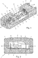
- number 1 denotes as a whole a power supply unit for exteriors that can advantageously be used for powering LED lighting apparatuses for exteriors.
- the power supply unit 1 is adapted to be interposed between a known single-phase electrical mains and a generic LED lighting apparatus or the like, and is capable of converting the alternating-current electric energy coming from the electrical mains into direct-current electric energy suitable for powering a LED lighting apparatus or any other electrical load that needs direct-current stabilized power supply.
- Power supply unit 1 in addition, is specifically structured to be installed and continuously operate outdoors, resisting bad weather.
- power supply unit 1 is basically made up of an electronic board 2, which is structured so as to receive at input the alternating-current electric energy preferably coming from a generic external single-phase electrical mains, and to provide at output direct-current electric energy preferably with a constant (stabilized) voltage and/or current; and of a protective outer casing which is hard and rigid and surrounds and protects the electronic board 2 from impacts and atmospheric agents.
- Clearly power supply unit 1 can also be used indoors, i.e. inside buildings and the like.
- the outer protecting casing basically consists of, or anyway comprises, a solid and compact composite-material block 3 with a monolithic structure, which is made of a resin loaded with grains and, optionally, also powders of one or more inert materials of mineral type, with sizes of the grains preferably smaller than 5 mm (millimetres); and electronic board 2 is completely embedded inside said solid and compact composite-material block 3.
- the amount of grains and, optionally, also powders of mineral-type inert material/s is furthermore greater than 30% and, optionally, also greater than 50% of the overall weight of the composite material that forms the solid and compact composite-material block 3.
- the resin is preferably a thermosetting resin and is preferably loaded with grains and, optionally, also powders of quartz (silicon dioxide), feldspar or other mineral.
- the composite material can also comprise grains and/or powders of marble and/or granite and/or other stone materials.
- the sizes of the inert-material grains embedded in the resin preferably are less than 3 mm (millimetres). Preferably, the sizes of the inert-material grains embedded in the resin are furthermore greater than 25 ⁇ m (micrometres).
- the sizes of the inert-material grains preferably range from 25 ⁇ m (micrometres) to 3 mm (millimetres).
- the solid and compact composite-material block 3 is preferably substantially parallelepiped in shape, and the electronic board 2 is preferably arranged substantially at centre of the solid and compact composite-material block 3.
- the solid and compact composite-material block 3 is preferably shaped like an ingot, and is preferably made of a thermosetting resin loaded with quartz grains and powders with sizes preferably ranging from 25 ⁇ m (micrometres) to 3 mm (millimetres).
- thermosetting resin is furthermore an epoxy-based resin. More in detail, the thermosetting resin is preferably a cycloaliphatic epoxy resin.
- the electronic board 2 comprises a printed circuit 4 preferably substantially rectangular in shape, and a series of known electric/electronic components that are suitably fixed on the printed circuit 4.
- the assembly of electric/electronic components is adapted to convert the alternating-current electric energy coming from the external electrical mains into a direct-current electric energy suitable for powering LED lighting apparatuses or any other electrical load requiring direct-current power supply.
- electronic board 2 preferably comprises: an AC/DC conversion module 5 of the switching type, which is adapted to convert the alternating-current electric energy coming from the external electrical mains into a direct-current electric energy, and which is preferably arranged in the central area of the printed circuit 4; and two filtering circuits 6 and 7, which are located on the printed circuit 4 upstream and downstream, respectively, of the AC/DC conversion module 5 and are structured to reduce/minimise high-frequency noises that occur at the input and at the output, respectively, of the AC/DC conversion module 5.
- the AC/DC conversion module 5 in turn comprises: a small shell-type transformer 9; a MOSFET switch 10; a rectifier 11; and a microprocessor (not shown in the figures) which commands the MOSFET switch 10.
- the filtering circuit 6 preferably comprises a passive EMI filter 13 and a series of preferably electrolytic and/or ceramic, capacitors 14 that are suitably connected to one another.
- the filtering circuit 7 preferably comprises a series of preferably electrolytic and/or ceramic, capacitors 15 that are suitably connected to one another.
- the electronic board 2 finally also comprises an overvoltage protection circuit 16 that is located upstream of the AC/DC conversion module 5 or of the filtering circuit 6, and is adapted to prevent that possible overvoltages arriving from the single-phase electrical mains may irreparably damage the electronic board 2.
- the power supply unit 1 is finally provided with input connectors 17 that are located on the outside of the solid and compact composite-material block 3 and are electrically connected to the input terminals of electronic board 2, so as to connect the electronic board 2 to the external electrical mains; and with output connectors 18 that are located on the outside of the solid and compact composite-material block 3, preferably on the opposite side relative to the input connectors 17, and are electrically connected to the output terminals of electronic board 2, so as to connect the electronic board 2 to the LED lighting apparatus or other electrical load requiring direct-current power supply.
- input connectors 17 and output connectors 18 are preferably located at the two axial ends of the substantially ingot-shaped, solid and compact composite-material block 3.
- the solid and compact composite-material block 3 is made of a hard and rigid material which is electrically insulating and also waterproof.
- the power supply unit 1 has relatively low manufacturing costs.
- the production of power supply unit 1 involves, in sequence, the steps of pouring the resin loaded with grains and, optionally, also powders of one or more inert-type mineral materials into a mould which is complementary in shaped to the solid and compact composite-material block 3, and which already accommodates the electronic board 2; and then subjecting the mould and the content thereof to a thermal baking cycle causes the polymerization/cross-linking and hardening of the resin.
- the power supply unit 1 does not need any more an protective outer shell made of metal material.
- the solid and compact composite-material block 3 is capable of protecting the electronic board 2 against impacts and bad weather, ensuring at same time an ideal dissipation of the heat that is normally produced by the electronic board 2.
- the particular monolithic structure of the solid and compact composite-material block 3 has a thermal resistance significantly lower than the overall thermal resistance of the silicone-gel and metal combination, thus improving dissipation of the heat produced by electronic board 2.
- the electronic board 2 may comprise two or more printed circuits 4 arranged beside and electrically connected to one another, and the electric/electronic components are suitably spread among the two or more printed circuits 4.
- the electronic board 2 may also receive, at input, direct-current electric energy coming, for example, from a known high-voltage and/or high-capacity battery pack, always providing, at output, direct-current electric energy preferably with a constant voltage and/or current.
Landscapes
- Engineering & Computer Science (AREA)
- Microelectronics & Electronic Packaging (AREA)
- Power Engineering (AREA)
- Dc-Dc Converters (AREA)
- Prostheses (AREA)
- Brushes (AREA)
Applications Claiming Priority (1)
| Application Number | Priority Date | Filing Date | Title |
|---|---|---|---|
| IT102018000010294A IT201800010294A1 (it) | 2018-11-13 | 2018-11-13 | Unita' di alimentazione per esterni |
Publications (1)
| Publication Number | Publication Date |
|---|---|
| EP3654741A1 true EP3654741A1 (fr) | 2020-05-20 |
Family
ID=65496875
Family Applications (1)
| Application Number | Title | Priority Date | Filing Date |
|---|---|---|---|
| EP19208993.6A Withdrawn EP3654741A1 (fr) | 2018-11-13 | 2019-11-13 | Unité d'alimentation électrique pour extérieurs |
Country Status (4)
| Country | Link |
|---|---|
| EP (1) | EP3654741A1 (fr) |
| KR (1) | KR20190001790U (fr) |
| CN (1) | CN210405107U (fr) |
| IT (1) | IT201800010294A1 (fr) |
Cited By (1)
| Publication number | Priority date | Publication date | Assignee | Title |
|---|---|---|---|---|
| WO2023046757A1 (fr) * | 2021-09-23 | 2023-03-30 | Vitesco Technologies Germany Gmbh | Module à semi-conducteur de puissance et chaîne cinématique pour un véhicule présentant un module à semi-conducteur de puissance de ce type |
Citations (4)
| Publication number | Priority date | Publication date | Assignee | Title |
|---|---|---|---|---|
| US20110013365A1 (en) * | 2009-07-16 | 2011-01-20 | Denso Corporation | Electronic control unit |
| US20120014059A1 (en) * | 2010-07-15 | 2012-01-19 | Jian-Hong Zeng | Power module |
| US8358514B2 (en) * | 2008-10-20 | 2013-01-22 | Denso Corporation | Electronic control device |
| EP3208902A1 (fr) * | 2014-10-15 | 2017-08-23 | Mitsuba Corporation | Commande et procédé de fabrication d'une commande |
-
2018
- 2018-11-13 IT IT102018000010294A patent/IT201800010294A1/it unknown
-
2019
- 2019-06-14 CN CN201920902781.1U patent/CN210405107U/zh not_active Expired - Fee Related
- 2019-06-24 KR KR2020190002630U patent/KR20190001790U/ko not_active Withdrawn
- 2019-11-13 EP EP19208993.6A patent/EP3654741A1/fr not_active Withdrawn
Patent Citations (4)
| Publication number | Priority date | Publication date | Assignee | Title |
|---|---|---|---|---|
| US8358514B2 (en) * | 2008-10-20 | 2013-01-22 | Denso Corporation | Electronic control device |
| US20110013365A1 (en) * | 2009-07-16 | 2011-01-20 | Denso Corporation | Electronic control unit |
| US20120014059A1 (en) * | 2010-07-15 | 2012-01-19 | Jian-Hong Zeng | Power module |
| EP3208902A1 (fr) * | 2014-10-15 | 2017-08-23 | Mitsuba Corporation | Commande et procédé de fabrication d'une commande |
Cited By (1)
| Publication number | Priority date | Publication date | Assignee | Title |
|---|---|---|---|---|
| WO2023046757A1 (fr) * | 2021-09-23 | 2023-03-30 | Vitesco Technologies Germany Gmbh | Module à semi-conducteur de puissance et chaîne cinématique pour un véhicule présentant un module à semi-conducteur de puissance de ce type |
Also Published As
| Publication number | Publication date |
|---|---|
| IT201800010294A1 (it) | 2020-05-13 |
| CN210405107U (zh) | 2020-04-24 |
| KR20190001790U (ko) | 2019-07-12 |
Similar Documents
| Publication | Publication Date | Title |
|---|---|---|
| US20250055048A1 (en) | Mobile Energy Supply System With Battery Modules, Battery Module and Method for Operating a Mobile Energy Supply System | |
| CN1224131C (zh) | 电池组件及其制造方法 | |
| JP7091878B2 (ja) | パワーモジュール、電力変換装置、及びパワーモジュールの製造方法 | |
| EP1104025B1 (fr) | Dispositif a semi-conducteur | |
| CN102315699B (zh) | 无线充电的实现装置 | |
| JP7345621B2 (ja) | 電力変換装置および電力変換装置の製造方法 | |
| KR20220160248A (ko) | 인버터 파워모듈 | |
| EP3654741A1 (fr) | Unité d'alimentation électrique pour extérieurs | |
| EP2792045A1 (fr) | Procédé pour la fabrication de chargeurs de batterie pour véhicules et chargeurs de batterie pouvant être obtenus ainsi | |
| WO2021086125A1 (fr) | Appareil de charge sans fil et moyen de locomotion le comprenant | |
| JP2017212774A (ja) | 電力変換器 | |
| JP6817560B2 (ja) | 電池管理システム | |
| JP2004087735A (ja) | 半導体装置 | |
| WO2016047174A1 (fr) | Dispositif de conversion de puissance | |
| WO2022227498A1 (fr) | Structure d'emballage de dispositif électronique de puissance appropriée pour un environnement de brouillard salin lourd | |
| US20250112170A1 (en) | Transformer Packages Providing Magnetostriction Management | |
| CN108885940B (zh) | 模块 | |
| CN118232190A (zh) | 配电箱及其制作方法 | |
| EP4654422A1 (fr) | Chargeur embarqué et véhicule | |
| CN116437561A (zh) | 模块化电路及电子设备 | |
| CN203104246U (zh) | 一种位置传感器内置的开关磁阻电机 | |
| CN209643069U (zh) | 一种双面陶瓷线路板 | |
| CN201194373Y (zh) | 变频发电机逆变电源模块 | |
| CN209199924U (zh) | 高压功率模块封装结构 | |
| CN207460681U (zh) | 一种采用新型灌封黑胶来灌封的电源 |
Legal Events
| Date | Code | Title | Description |
|---|---|---|---|
| PUAI | Public reference made under article 153(3) epc to a published international application that has entered the european phase |
Free format text: ORIGINAL CODE: 0009012 |
|
| STAA | Information on the status of an ep patent application or granted ep patent |
Free format text: STATUS: THE APPLICATION HAS BEEN PUBLISHED |
|
| AK | Designated contracting states |
Kind code of ref document: A1 Designated state(s): AL AT BE BG CH CY CZ DE DK EE ES FI FR GB GR HR HU IE IS IT LI LT LU LV MC MK MT NL NO PL PT RO RS SE SI SK SM TR |
|
| AX | Request for extension of the european patent |
Extension state: BA ME |
|
| STAA | Information on the status of an ep patent application or granted ep patent |
Free format text: STATUS: REQUEST FOR EXAMINATION WAS MADE |
|
| 17P | Request for examination filed |
Effective date: 20201120 |
|
| RBV | Designated contracting states (corrected) |
Designated state(s): AL AT BE BG CH CY CZ DE DK EE ES FI FR GB GR HR HU IE IS IT LI LT LU LV MC MK MT NL NO PL PT RO RS SE SI SK SM TR |
|
| STAA | Information on the status of an ep patent application or granted ep patent |
Free format text: STATUS: EXAMINATION IS IN PROGRESS |
|
| 17Q | First examination report despatched |
Effective date: 20220315 |
|
| STAA | Information on the status of an ep patent application or granted ep patent |
Free format text: STATUS: THE APPLICATION IS DEEMED TO BE WITHDRAWN |
|
| 18D | Application deemed to be withdrawn |
Effective date: 20220726 |