EP3655290B1 - Kostengünstige kamera - Google Patents
Kostengünstige kamera Download PDFInfo
- Publication number
- EP3655290B1 EP3655290B1 EP18844249.5A EP18844249A EP3655290B1 EP 3655290 B1 EP3655290 B1 EP 3655290B1 EP 18844249 A EP18844249 A EP 18844249A EP 3655290 B1 EP3655290 B1 EP 3655290B1
- Authority
- EP
- European Patent Office
- Prior art keywords
- view
- field
- vehicle
- lens
- image sensor
- Prior art date
- Legal status (The legal status is an assumption and is not a legal conclusion. Google has not performed a legal analysis and makes no representation as to the accuracy of the status listed.)
- Active
Links
Images


Classifications
-
- B—PERFORMING OPERATIONS; TRANSPORTING
- B60—VEHICLES IN GENERAL
- B60R—VEHICLES, VEHICLE FITTINGS, OR VEHICLE PARTS, NOT OTHERWISE PROVIDED FOR
- B60R11/00—Arrangements for holding or mounting articles, not otherwise provided for
- B60R11/04—Mounting of cameras operative during drive; Arrangement of controls thereof relative to the vehicle
-
- B—PERFORMING OPERATIONS; TRANSPORTING
- B60—VEHICLES IN GENERAL
- B60Q—ARRANGEMENT OF SIGNALLING OR LIGHTING DEVICES, THE MOUNTING OR SUPPORTING THEREOF OR CIRCUITS THEREFOR, FOR VEHICLES IN GENERAL
- B60Q9/00—Arrangement or adaptation of signal devices not provided for in one of main groups B60Q1/00 - B60Q7/00, e.g. haptic signalling
- B60Q9/008—Arrangement or adaptation of signal devices not provided for in one of main groups B60Q1/00 - B60Q7/00, e.g. haptic signalling for anti-collision purposes
-
- B—PERFORMING OPERATIONS; TRANSPORTING
- B60—VEHICLES IN GENERAL
- B60R—VEHICLES, VEHICLE FITTINGS, OR VEHICLE PARTS, NOT OTHERWISE PROVIDED FOR
- B60R1/00—Optical viewing arrangements; Real-time viewing arrangements for drivers or passengers using optical image capturing systems, e.g. cameras or video systems specially adapted for use in or on vehicles
- B60R1/20—Real-time viewing arrangements for drivers or passengers using optical image capturing systems, e.g. cameras or video systems specially adapted for use in or on vehicles
- B60R1/22—Real-time viewing arrangements for drivers or passengers using optical image capturing systems, e.g. cameras or video systems specially adapted for use in or on vehicles for viewing an area outside the vehicle, e.g. the exterior of the vehicle
- B60R1/23—Real-time viewing arrangements for drivers or passengers using optical image capturing systems, e.g. cameras or video systems specially adapted for use in or on vehicles for viewing an area outside the vehicle, e.g. the exterior of the vehicle with a predetermined field of view
- B60R1/24—Real-time viewing arrangements for drivers or passengers using optical image capturing systems, e.g. cameras or video systems specially adapted for use in or on vehicles for viewing an area outside the vehicle, e.g. the exterior of the vehicle with a predetermined field of view in front of the vehicle
-
- B—PERFORMING OPERATIONS; TRANSPORTING
- B60—VEHICLES IN GENERAL
- B60R—VEHICLES, VEHICLE FITTINGS, OR VEHICLE PARTS, NOT OTHERWISE PROVIDED FOR
- B60R1/00—Optical viewing arrangements; Real-time viewing arrangements for drivers or passengers using optical image capturing systems, e.g. cameras or video systems specially adapted for use in or on vehicles
- B60R1/20—Real-time viewing arrangements for drivers or passengers using optical image capturing systems, e.g. cameras or video systems specially adapted for use in or on vehicles
- B60R1/22—Real-time viewing arrangements for drivers or passengers using optical image capturing systems, e.g. cameras or video systems specially adapted for use in or on vehicles for viewing an area outside the vehicle, e.g. the exterior of the vehicle
- B60R1/23—Real-time viewing arrangements for drivers or passengers using optical image capturing systems, e.g. cameras or video systems specially adapted for use in or on vehicles for viewing an area outside the vehicle, e.g. the exterior of the vehicle with a predetermined field of view
- B60R1/26—Real-time viewing arrangements for drivers or passengers using optical image capturing systems, e.g. cameras or video systems specially adapted for use in or on vehicles for viewing an area outside the vehicle, e.g. the exterior of the vehicle with a predetermined field of view to the rear of the vehicle
-
- B—PERFORMING OPERATIONS; TRANSPORTING
- B60—VEHICLES IN GENERAL
- B60R—VEHICLES, VEHICLE FITTINGS, OR VEHICLE PARTS, NOT OTHERWISE PROVIDED FOR
- B60R1/00—Optical viewing arrangements; Real-time viewing arrangements for drivers or passengers using optical image capturing systems, e.g. cameras or video systems specially adapted for use in or on vehicles
- B60R1/20—Real-time viewing arrangements for drivers or passengers using optical image capturing systems, e.g. cameras or video systems specially adapted for use in or on vehicles
- B60R1/22—Real-time viewing arrangements for drivers or passengers using optical image capturing systems, e.g. cameras or video systems specially adapted for use in or on vehicles for viewing an area outside the vehicle, e.g. the exterior of the vehicle
- B60R1/28—Real-time viewing arrangements for drivers or passengers using optical image capturing systems, e.g. cameras or video systems specially adapted for use in or on vehicles for viewing an area outside the vehicle, e.g. the exterior of the vehicle with an adjustable field of view
-
- B—PERFORMING OPERATIONS; TRANSPORTING
- B60—VEHICLES IN GENERAL
- B60R—VEHICLES, VEHICLE FITTINGS, OR VEHICLE PARTS, NOT OTHERWISE PROVIDED FOR
- B60R1/00—Optical viewing arrangements; Real-time viewing arrangements for drivers or passengers using optical image capturing systems, e.g. cameras or video systems specially adapted for use in or on vehicles
- B60R1/20—Real-time viewing arrangements for drivers or passengers using optical image capturing systems, e.g. cameras or video systems specially adapted for use in or on vehicles
- B60R1/29—Real-time viewing arrangements for drivers or passengers using optical image capturing systems, e.g. cameras or video systems specially adapted for use in or on vehicles for viewing an area inside the vehicle, e.g. for viewing passengers or cargo
-
- B—PERFORMING OPERATIONS; TRANSPORTING
- B60—VEHICLES IN GENERAL
- B60W—CONJOINT CONTROL OF VEHICLE SUB-UNITS OF DIFFERENT TYPE OR DIFFERENT FUNCTION; CONTROL SYSTEMS SPECIALLY ADAPTED FOR HYBRID VEHICLES; ROAD VEHICLE DRIVE CONTROL SYSTEMS FOR PURPOSES NOT RELATED TO THE CONTROL OF A PARTICULAR SUB-UNIT
- B60W50/00—Details of control systems for road vehicle drive control not related to the control of a particular sub-unit, e.g. process diagnostic or vehicle driver interfaces
- B60W50/08—Interaction between the driver and the control system
- B60W50/14—Means for informing the driver, warning the driver or prompting a driver intervention
-
- G—PHYSICS
- G02—OPTICS
- G02B—OPTICAL ELEMENTS, SYSTEMS OR APPARATUS
- G02B13/00—Optical objectives specially designed for the purposes specified below
- G02B13/16—Optical objectives specially designed for the purposes specified below for use in conjunction with image converters or intensifiers, or for use with projectors, e.g. objectives for projection TV
-
- G—PHYSICS
- G02—OPTICS
- G02B—OPTICAL ELEMENTS, SYSTEMS OR APPARATUS
- G02B26/00—Optical devices or arrangements for the control of light using movable or deformable optical elements
- G02B26/004—Optical devices or arrangements for the control of light using movable or deformable optical elements based on a displacement or a deformation of a fluid
- G02B26/005—Optical devices or arrangements for the control of light using movable or deformable optical elements based on a displacement or a deformation of a fluid based on electrowetting
-
- G—PHYSICS
- G06—COMPUTING OR CALCULATING; COUNTING
- G06V—IMAGE OR VIDEO RECOGNITION OR UNDERSTANDING
- G06V20/00—Scenes; Scene-specific elements
- G06V20/50—Context or environment of the image
- G06V20/56—Context or environment of the image exterior to a vehicle by using sensors mounted on the vehicle
-
- G—PHYSICS
- G06—COMPUTING OR CALCULATING; COUNTING
- G06V—IMAGE OR VIDEO RECOGNITION OR UNDERSTANDING
- G06V20/00—Scenes; Scene-specific elements
- G06V20/50—Context or environment of the image
- G06V20/56—Context or environment of the image exterior to a vehicle by using sensors mounted on the vehicle
- G06V20/58—Recognition of moving objects or obstacles, e.g. vehicles or pedestrians; Recognition of traffic objects, e.g. traffic signs, traffic lights or roads
-
- H—ELECTRICITY
- H04—ELECTRIC COMMUNICATION TECHNIQUE
- H04N—PICTORIAL COMMUNICATION, e.g. TELEVISION
- H04N23/00—Cameras or camera modules comprising electronic image sensors; Control thereof
- H04N23/50—Constructional details
- H04N23/55—Optical parts specially adapted for electronic image sensors; Mounting thereof
-
- H—ELECTRICITY
- H04—ELECTRIC COMMUNICATION TECHNIQUE
- H04N—PICTORIAL COMMUNICATION, e.g. TELEVISION
- H04N23/00—Cameras or camera modules comprising electronic image sensors; Control thereof
- H04N23/58—Means for changing the camera field of view without moving the camera body, e.g. nutating or panning of optics or image sensors
-
- H—ELECTRICITY
- H04—ELECTRIC COMMUNICATION TECHNIQUE
- H04N—PICTORIAL COMMUNICATION, e.g. TELEVISION
- H04N23/00—Cameras or camera modules comprising electronic image sensors; Control thereof
- H04N23/60—Control of cameras or camera modules
- H04N23/69—Control of means for changing angle of the field of view, e.g. optical zoom objectives or electronic zooming
-
- H—ELECTRICITY
- H04—ELECTRIC COMMUNICATION TECHNIQUE
- H04N—PICTORIAL COMMUNICATION, e.g. TELEVISION
- H04N23/00—Cameras or camera modules comprising electronic image sensors; Control thereof
- H04N23/60—Control of cameras or camera modules
- H04N23/695—Control of camera direction for changing a field of view, e.g. pan, tilt or based on tracking of objects
-
- H—ELECTRICITY
- H04—ELECTRIC COMMUNICATION TECHNIQUE
- H04N—PICTORIAL COMMUNICATION, e.g. TELEVISION
- H04N23/00—Cameras or camera modules comprising electronic image sensors; Control thereof
- H04N23/60—Control of cameras or camera modules
- H04N23/698—Control of cameras or camera modules for achieving an enlarged field of view, e.g. panoramic image capture
-
- B—PERFORMING OPERATIONS; TRANSPORTING
- B60—VEHICLES IN GENERAL
- B60R—VEHICLES, VEHICLE FITTINGS, OR VEHICLE PARTS, NOT OTHERWISE PROVIDED FOR
- B60R2300/00—Details of viewing arrangements using cameras and displays, specially adapted for use in a vehicle
- B60R2300/10—Details of viewing arrangements using cameras and displays, specially adapted for use in a vehicle characterised by the type of camera system used
- B60R2300/101—Details of viewing arrangements using cameras and displays, specially adapted for use in a vehicle characterised by the type of camera system used using cameras with adjustable capturing direction
-
- G—PHYSICS
- G02—OPTICS
- G02B—OPTICAL ELEMENTS, SYSTEMS OR APPARATUS
- G02B7/00—Mountings, adjusting means, or light-tight connections, for optical elements
- G02B7/02—Mountings, adjusting means, or light-tight connections, for optical elements for lenses
- G02B7/04—Mountings, adjusting means, or light-tight connections, for optical elements for lenses with mechanism for focusing or varying magnification
- G02B7/08—Mountings, adjusting means, or light-tight connections, for optical elements for lenses with mechanism for focusing or varying magnification adapted to co-operate with a remote control mechanism
Definitions
- the present invention generally relates to imaging systems (cameras) used in vehicles.
- FR 3 041 458 A1 describes an imaging device including an image sensor, a lens, a control module designed to trigger a plurality of shots by the image sensor at successive instants, so as to acquire a respective plurality of images having a given spatial resolution, and an analysis module designed to produce a super-resolved image presenting a spatial resolution greater than the given spatial resolution of the separate images.
- WO 2006/002746 A1 discloses a shooting method comprising, in response to a shot release: - the capture of a first image, according to a first shooting field, using a camera equipped with a variable focus lens set to a first focal length, - the automatic search in the first image of interest zones, and when at least one interest zone is found, - the automatic modification of the focal length to tighten the shooting field around the interest zone, - the automatic capture of at least one second image according to the tightened shooting field, and - the automatic creation of a composite image by combining the first image and the second image.
- US 6 369 954 B1 discloses a variable focus lens comprising a chamber filled with a first liquid, a drop of a second liquid being disposed at rest on a region of a first surface of an insulating wall of the chamber, the first and second liquids being non miscible, of different optical indexes and of substantially same density.
- the first liquid is conductive and the second liquid is insulating.
- the lens further comprises means for applying a voltage between the conductor liquid and an electrode placed on the second surface of said wall; and centering means for maintaining the centering of the edge of the drop while the voltage is applied and for controlling the shape thereof.
- US 2015/0237326 A1 describes a 3D image capture apparatus that uses digital images of an object from multiple view points, which can be used to generate a 3D image of the object.
- the apparatus includes an image sensor, a lens adjacent the image sensor, and an active optical component adjacent the lens and opposite the image sensor.
- An aperture component is located between the active optical component and the lens, and the aperture component has an aperture for allowing passage of light to the image sensor.
- the active optical component is changeable between first and second shapes.
- the first shape provides a first optical wavefront through the aperture and lens to the image sensor from a first view angle of an object
- the second shape provides a second optical wavefront through the aperture and lens to the image sensor from a second view angle of the object.
- the second optical wavefront is shifted by the active optical component on the image sensor with respect to the first optical wavefront in order to provide multiple view-angle images along a single optical channel.
- WO 2013/032165 A1 describes a network camera and a photographing method thereof.
- the network camera includes a lens module comprising a plurality of lenses having incident paths different from each other, a prism reflecting light incident through the lens module, a prism driving module rotating the prism, and a controller controlling the prism through the prism driving module.
- the prism reflects lights incident through the incident paths different from each other by performing a rotation operation according to a control of the prism driving module.
- ATSUSHI TAKEI ET AL "Angle-Tunable Liquid Wedge Prism Driven by Electrowetting", JOURNAL OF MICROELECTROMECHANICAL SYSTEMS, IEEE SERVICE CENTER, US, vol. 16, no. 6, 1 December 2007 (2007-12-01), pages 1537-1542, ISSN: 1057-7157, DOI: 10.1109/JMEMS.2007.906074 describes a tunable wedge prism by electrowetting actuation.
- the prism can shift the field of view to the left or to the right and is useful for small cameras and endoscopes because its field of view can be changed without the need for large instruments. It consists of two plates that face each other, and a liquid is sandwiched between them.
- the liquid and plates form a wedge when the angle between the plates is changed. Electrowetting is used to change the angle between the plates.
- the wedge prism is small because the liquid driven by electrowetting works as a prism.
- the prism produces a clear field of view because its optical flatness is determined by the flatness of the plates.
- Automotive cameras are used for a wide variety of functions in a vehicle. Such uses include control of vehicle equipment to supplementing a driver's vision of the environment surrounding the vehicle. Cameras that supplement a driver's vision include rearward-facing cameras such as a camera for a reverse camera display (RCD) system and a camera for a full display mirror (FDM) system. Cameras for RCD systems and FDM systems may be aimed in approximately the same direction but have different fields of view (FOV) and focal points. Thus, in a vehicle that provides both RCD and FDM systems, two cameras have been mounted to the rear of the vehicle with each camera providing images for different ones of the two systems.
- RCD reverse camera display
- FDM full display mirror
- Automotive cameras tend to be much lower resolution than consumer products due to reliability requirements. For example, the latest automotive-grade parts are 2MP, with recent announcements of 7.5MP sensors coming in 2018. The reason for the increase in resolution is to handle the NCAP requirements for 2021 in Europe where forward-facing sensors must have enough resolution to see pedestrians at the side of the vehicle and still have enough resolution in the center. A similar problem exists in the rearward direction where requirements of 170 ppi over 50 degrees, with 1600 pixels wide, implies a 24MP sensor necessary for 180° FOV surround system with a standard fixed-focus lens. Thus, digital high definition (HD) cameras have been used to provide these higher resolutions. However, these digital HD cameras require expensive serializer/deserializer pairs and associated connectors (coaxial connectors). As used herein an HD camera/image sensor has a signal to noise ratio of at least about 90dB.
- Analog HD cameras provide the benefit of not requiring expensive serializer/deserializer pairs and associated connectors of their digital counterparts. Thus, less expensive twisted pair cables and conventional crimp and snap connector systems may be used.
- a suitable analog encoder is available from Techpoint Inc. of San Jose, California.
- Fig. 1 shows an example of an imaging system 10 having a HD image sensor 20, a variable focus lens such as an electrowetting lens 30 positioned in front of the image sensor 20 and configured to change at least one optical characteristic in response to an electrical stimulus so as to change a field of view of the image sensor 20, and a controller 40 coupled to the variable focus lens 30 and configured to select a field of view of the image sensor 20 by selecting the electrical stimulus to be applied to the variable focus lens 30.
- the variable focus lens 30 may also be used for auto-focusing.
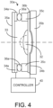
- variable focus lens 30 may take any form known in the art including the forms shown in Figs. 1 and 4 .
- the variable focus lens 30 is an electrowetting lens, which includes an oil lens 32 that may take various shapes to form a variable lens in response to the application of an electrical stimulus such as the application of a selected voltage to one or more electrodes 34 within the electrowetting lens 30.
- the lens 30 may include two glass substrates 35a and 35b that combine with electrodes 34a, 34b and insulating member 36a to form a chamber in which the oil lens 32 is disposed. The remainder of the chamber in which the oil lens 32 is located is filled with another fluid such as water 33 that does not mix with the oil lens 32.
- the electrode 34b that contacts the oil lens 32 may be coated with an insulator material.
- Figs. 2A, 2B, and 2C show three examples of the shapes the oil lens 32 may form in response to two different voltages applied to electrodes 34a and 34b.
- the oil lens 32 takes the shape of a convex glass lens and the electrowetting lens 30 functions as a bi-convex lens.
- the oil lens 32 takes the shape of a concave glass lens and the electrowetting lens 30 functions as a bi-concave lens.
- Fig. 1 the oil lens 32 takes the shape of a convex glass lens and the electrowetting lens 30 functions as a bi-concave lens.
- the oil lens 32 takes a tilted or rotated shape so that the electrowetting lens 30 shifts the field of view to one direction (i.e., left, right, up, or down).
- the focal length may be changed as may the direction of the optical axis.
- the electrowetting lens 30 may be used to change the field of view of the image sensor 20 as well as to pan the field of view across the imaging surface of the image sensor 20.
- the electrowetting lens 30a shown in Fig. 4 is similar to that shown in Fig. 1 except that the configuration of electrode 34b is different and rear glass substrate 35b includes a spherical recess with the electrode 34b coated over the entire surface of substrate 35b.
- An insulating layer 36b is provided across the entire surface of electrode 34b and fills the electrode-coated spherical recess in substrate 35b.
- an annular glass ring 35c may be provided about the periphery of the chamber between substrates 35a and 35b. In this lens configuration, a drop of oil is centered by a gradient in the electric field applied through electrodes 34a and 34b to form oil lens 32.
- FIG. 3A and 3B One example of an application for imaging system 10 not encompassed by the claimed invention would be a rear vision camera 10a of a vehicle 18 as shown in Figs. 3A and 3B .
- the field of view 15a of the rear vision camera 10a could be dynamically changed without reducing the resolution of the image output from the rear vision camera 10a.
- the field of view could be shifted to keep the image of any detected vehicle within the image.
- the field of view could be widened or narrowed as shown in Figs. 3A and 3B depending upon whether the vehicle was in reverse (for RCD) or driving forward (for FDM), or depending upon the forward speed of the vehicle or the type of road upon which the vehicle is traveling.
- a single camera may be used for both RCD and FDM applications.
- the rear vision camera 10a may be located at the rear of the vehicle or at the sides of the vehicle as cameras 10a' and 10a" with respective variable fields of view 15a' and 15a".
- the images captured by the rear vision cameras 10a, 10a', and 10a" may be displayed on a display located in the rearview mirror 16 or other location in the instrument panel or console. Additionally or alternatively, the images may be processed for use in autonomous vehicle control or a driver assist function, such as parking assist, blind spot detection, rear collision warning, lane departure warning, lane keeping assist, etc.
- FIG. 3A Another example of a vehicle application for imaging system 10 not encompassed by the claimed invention would be as a forward vision camera 10b as shown in Fig. 3A .
- Such forward vision cameras 10b may be mounted at or near the rearview mirror 16 to capture images forward of the vehicle through its windshield. Images captured by the forward vision camera 10b may be used for a number of different driver assist functions or autonomous vehicle control functions. For example, the images may be used for headlamp control, lane departure warning, parking assist, adaptive cruise control, lane keeping assist, forward collision warning, object detection, pedestrian detection, and traffic sign recognition. However, it may be desirable to use a wider or narrower field of view 15b for each of these functions so as to limit the information in the captured images to that information that is relevant for the particular function.
- the provision of the electrowetting lens 30 in a forward vision camera 10b provides the advantage of changing the field of view for a selected function without a loss in resolution. Further, the ability of the electrowetting lens to shift the field of view 15b left or right allows the forward vision camera 10b to look in the direction of an upcoming turn.
- the forward vision camera 10b may advantageously maintain a high pixel count per degree of field of view when the field of view is narrowed to focus on distant objects. This allows for more accurate detection of vehicles and other objects at greater distances. Likewise, the field of view may be changed to look ahead in the direction of an upcoming turn so that vehicles on the turn may be detected more quickly and accurately.
- FIG. 3A Another example of a vehicle application for imaging system 10 according to the claimed invention is an interior vision camera 10c as shown in Fig. 3A .
- Such interior vision cameras 10c may be mounted at or near the rearview mirror 16, an upper console, or reading light assembly in order to capture images inside the vehicle and display the images to the driver or other occupants.
- a camera 10c may be mounted to view back seat passengers and display the images to the driver on a display that may be mounted in the rearview mirror 16 or other location in the instrument panel or console. This is particularly useful if one of the passengers is a baby and even more advantageous if the baby is in a car seat facing rearward.
- the field of view 15c may be shifted around the interior of the vehicle so as to view a particular passenger or location in the vehicle.
- the field of view 15c may also be widened or narrowed to capture front seat passengers or focus on rear seat passengers.
- Automated control may be used for video conferences so as to shift the field of view to whichever vehicle occupant is speaking.
- variable focus lens 30 By using the variable focus lens 30 in imaging systems 10 used in a vehicle, one can avoid having to only rely upon digital zooming for changing a field of view, which results in a reduction in the resolution of the images captured by the system. Further, to the extent one intends to avoid this by providing a mechanical zoom lens, such a mechanical zoom lens is much more complex to make and subject to breakage.
- variable focus lens 30, 30a was oscillated between two or more images or fields of view, a first image stream having a first field of view could be supplied to a first display 50a and a second image stream having a different second field of view may be supplied to a second display 50b and thus two or more different image streams could be captured and displayed in real time.
- the different image streams could also be displayed in different display areas of one display 50a.
- Using one camera to collect multiple images is an advantage over using multiple cameras. For example, if the camera was set to oscillate between two images at 30Hz, one could update two different images on two different displays or two different display zones at 15Hz.
- the imaging system 10 may also find advantageous application in security cameras, particularly for those applications where two separate image sensors are used to capture retinal images of both a person's eyes.
- the field of view may be shifted from one eye to the other and thereby eliminate the need for two separate cameras.
- the field of view may be initially set to wide to capture a person's face and identify the location of their eyes and then zoom in on each eye. This would make it more practical to implement biometric screening security measures (particularly retinal imaging) in mobile devices, which typically only have one camera aimed in any one direction.
- Security cameras having an electrowetting lens with a variable field of view may be used in home security systems as well as in smoke detectors and strobe light fixtures.
- a vehicle camera such as camera 10c may be used for security purposes to scan the irises of the driver prior to starting the vehicle.
- the imaging system may also be used for scanning of a person's face for a facial recognition system.
- imaging system 10 is shown as having just an electrowetting lens 30 in front of image sensor 20, additional conventional lenses may be used in combination with the electrowetting lens 30 to obtain the desired fields of view and focus. Further, other forms of variable focus lenses may be used in combination with the HD image sensor 20.
- An example of an electrowetting lens that may be used is available from Invenios of Santa Barbara, California. Such a lens can provide a 130° FOV for RCD applications and a 50° FOV for FDM applications with crisp images.
- controller 40 may include various forms of control logic and image processing circuitry.
- a dewarp engine may be provided in controller 40.
- an analog HD image sensor 20 one may want to lower the resolution transmitted so that image signal processing (ISP) may be performed in the camera module (HDR reconstruct, windowing, etc.). Therefore, an ISP processor with dewarp, e.g. GEO Semi GW5, may be provided in the camera module portion of the imaging system 10, which would include HD image sensor 20, variable focus lens 30, and controller 40, with an analog output from the camera.
- ISP image signal processing
Landscapes
- Engineering & Computer Science (AREA)
- Multimedia (AREA)
- Mechanical Engineering (AREA)
- Physics & Mathematics (AREA)
- Signal Processing (AREA)
- General Physics & Mathematics (AREA)
- Optics & Photonics (AREA)
- Theoretical Computer Science (AREA)
- Automation & Control Theory (AREA)
- Human Computer Interaction (AREA)
- Transportation (AREA)
- Studio Devices (AREA)
Claims (5)
- Ein Fahrzeug, das ein Bildgebungssystem (10) umfasst, wobei das Bildgebungssystem (10) Folgendes umfasst:einen Bildsensor (20);eine Elektrobenetzungslinse (30; 30a), die vor dem Bildsensor (20) positioniert ist und dazu konfiguriert ist, mindestens eine optische Eigenschaft als Reaktion auf einen elektrischen Reiz zu ändern, um so ein Sichtfeld des Bildsensors zu ändern; undeine Steuerung (40), die mit der Elektrobenetzungslinse (30; 30a) gekoppelt ist und konfiguriert ist, um ein Sichtfeld (15c) des Bildsensors (20) durch Auswahl des an die Elektrobenetzungslinse (30; 30a) anzulegenden elektrischen Stimulus auszuwählen,wobei das Bildgebungssystem (10) dadurch gekennzeichnet ist, dassdas Bildgebungssystem (10) eine Innenraumkamera (10c) des Fahrzeugs ist, wobei die Steuerung (40) zwei verschiedene elektrische Stimuli auswählt, um das Sichtfeld des Bildsensors (20) abwechselnd hin- und herzubewegen, um einen ersten Bildstrom mit einem ersten Sichtfeld und einen zweiten Bildstrom mit einem zweiten Sichtfeld zu erhalten,wobei die Steuerung (40) entweder den ersten Bildstrom an eine erste Anzeige (50a) und den zweiten Bildstrom an eine zweite Anzeige (50b) liefert oder den ersten Bildstrom und den zweiten Bildstrom an die erste Anzeige (50a) liefert, um sie gleichzeitig in verschiedenen Anzeigebereichen der ersten Anzeige (50a) anzuzeigen,wobei die Innenraumkamera (10c) konfiguriert ist, um Bilder im Inneren des Fahrzeugs zu erfassen und den ersten Bildstrom und den zweiten Bildstrom einem Fahrer oder Insassen des Fahrzeugs anzuzeigen, undwobei eine Änderung des Sichtfeldes (15c) durch automatische Steuerung bewirkt wird.
- Das Fahrzeug nach Anspruch 1, wobei die Steuerung (40) den an die Elektrobenetzungslinse (30; 30a) anzulegenden elektrischen Reiz variiert, um dadurch zu bewirken, dass das Sichtfeld verschoben wird.
- Das Fahrzeug nach irgendeinem der Ansprüche 1 bis 2, wobei die Steuerung (40) den an die Elektrobenetzungslinse (30; 30a) anzulegenden elektrischen Reiz variiert, um dadurch zu bewirken, dass das Sichtfeld (15c) verengt oder erweitert wird.
- Das Fahrzeug nach irgendeinem der Ansprüche von 1 bis 3, wobei der elektrische Reiz mindestens einer von einer angelegten Spannung und einem elektrischen Feldgradienten ist.
- Das Fahrzeug nach irgendeinem der Ansprüche von 1 bis 4, wobei die Ausgabe des Bildsensors ein analoges Format ist.
Applications Claiming Priority (2)
| Application Number | Priority Date | Filing Date | Title |
|---|---|---|---|
| US201762543421P | 2017-08-10 | 2017-08-10 | |
| PCT/US2018/046274 WO2019033000A1 (en) | 2017-08-10 | 2018-08-10 | LOW COST CAMERA |
Publications (3)
| Publication Number | Publication Date |
|---|---|
| EP3655290A1 EP3655290A1 (de) | 2020-05-27 |
| EP3655290A4 EP3655290A4 (de) | 2020-08-26 |
| EP3655290B1 true EP3655290B1 (de) | 2024-11-27 |
Family
ID=65271792
Family Applications (1)
| Application Number | Title | Priority Date | Filing Date |
|---|---|---|---|
| EP18844249.5A Active EP3655290B1 (de) | 2017-08-10 | 2018-08-10 | Kostengünstige kamera |
Country Status (4)
| Country | Link |
|---|---|
| US (1) | US20190047488A1 (de) |
| EP (1) | EP3655290B1 (de) |
| CN (1) | CN110785321B (de) |
| WO (1) | WO2019033000A1 (de) |
Families Citing this family (3)
| Publication number | Priority date | Publication date | Assignee | Title |
|---|---|---|---|---|
| US11320830B2 (en) | 2019-10-28 | 2022-05-03 | Deere & Company | Probabilistic decision support for obstacle detection and classification in a working area |
| CN117584856A (zh) * | 2023-11-21 | 2024-02-23 | 北京集度科技有限公司 | 监控系统、车辆、监控方法和计算机程序产品 |
| WO2025178907A1 (en) * | 2024-02-19 | 2025-08-28 | Regents Of The University Of Colorado A Body Corporate | Methods and apparatus for laterally shifting widefield images |
Citations (1)
| Publication number | Priority date | Publication date | Assignee | Title |
|---|---|---|---|---|
| WO2013032165A1 (en) * | 2011-08-31 | 2013-03-07 | Lg Innotek Co., Ltd. | Network camera and photographing method thereof |
Family Cites Families (21)
| Publication number | Priority date | Publication date | Assignee | Title |
|---|---|---|---|---|
| FR2769375B1 (fr) * | 1997-10-08 | 2001-01-19 | Univ Joseph Fourier | Lentille a focale variable |
| JP4185468B2 (ja) * | 2004-03-29 | 2008-11-26 | 富士フイルム株式会社 | 露光装置及び撮影画像の補正方法 |
| FR2872661B1 (fr) * | 2004-07-05 | 2006-09-22 | Eastman Kodak Co | Procede et dispositif de prise de vue a resolution multiplie |
| JP2006217131A (ja) * | 2005-02-02 | 2006-08-17 | Matsushita Electric Ind Co Ltd | 撮像装置 |
| JP2009515213A (ja) * | 2005-11-02 | 2009-04-09 | コーニンクレッカ フィリップス エレクトロニクス エヌ ヴィ | 3次元表示のための光学システム |
| JP5170961B2 (ja) * | 2006-02-01 | 2013-03-27 | ソニー株式会社 | 画像処理システム、画像処理装置および方法、プログラム、並びに記録媒体 |
| US7310190B2 (en) * | 2006-02-09 | 2007-12-18 | Delphi Technologies, Inc. | Vehicle imaging system with windshield condition determination |
| US9304305B1 (en) * | 2008-04-30 | 2016-04-05 | Arete Associates | Electrooptical sensor technology with actively controllable optics, for imaging |
| KR101071362B1 (ko) * | 2011-03-25 | 2011-10-07 | 위재영 | 차량의 물체 거리 인식 시스템 및 작동 방법 |
| KR101832266B1 (ko) * | 2011-03-31 | 2018-02-27 | 삼성전자주식회사 | 입체 영상 표시 장치 |
| US8408765B2 (en) * | 2011-05-12 | 2013-04-02 | Delphi Technologies, Inc. | Light distribution pattern control using object detection and electrowetting lenses |
| US8503088B2 (en) * | 2011-12-21 | 2013-08-06 | Delphi Technologies, Inc. | Windshield display system using electrowetting lenses |
| KR101984701B1 (ko) * | 2012-11-13 | 2019-05-31 | 삼성전자주식회사 | 전기습윤 렌즈 어레이를 포함하는 3차원 영상 디스플레이 장치 및 3차원 영상 획득 장치 |
| US9389342B2 (en) * | 2013-03-07 | 2016-07-12 | Wisconsin Alumni Research Foundation | Variable focus lens system |
| US20160107576A1 (en) * | 2013-11-05 | 2016-04-21 | Delphi Technologies, Inc. | Multiple imager vehicle optical sensor system |
| US20150237326A1 (en) * | 2014-02-14 | 2015-08-20 | 3M Innovative Properties Company | Sole channel 3d image capture apparatus |
| WO2016120874A1 (en) * | 2015-01-28 | 2016-08-04 | Edelstein Eliezer | Vision system |
| US10040394B2 (en) * | 2015-06-17 | 2018-08-07 | Geo Semiconductor Inc. | Vehicle vision system |
| FR3041458B1 (fr) * | 2015-09-18 | 2020-02-28 | Valeo Schalter Und Sensoren Gmbh | Dispositif d'imagerie, vehicule automobile equipe d'un tel dispositif d'imagerie, et procede associe |
| KR101822895B1 (ko) * | 2016-04-07 | 2018-01-29 | 엘지전자 주식회사 | 차량 운전 보조 장치 및 차량 |
| TWI781985B (zh) * | 2017-03-09 | 2022-11-01 | 美商康寧公司 | 具有自動對焦與光學圖像穩定功能的相機模組 |
-
2018
- 2018-08-10 EP EP18844249.5A patent/EP3655290B1/de active Active
- 2018-08-10 WO PCT/US2018/046274 patent/WO2019033000A1/en not_active Ceased
- 2018-08-10 CN CN201880040903.9A patent/CN110785321B/zh active Active
- 2018-08-10 US US16/101,086 patent/US20190047488A1/en not_active Abandoned
Patent Citations (1)
| Publication number | Priority date | Publication date | Assignee | Title |
|---|---|---|---|---|
| WO2013032165A1 (en) * | 2011-08-31 | 2013-03-07 | Lg Innotek Co., Ltd. | Network camera and photographing method thereof |
Non-Patent Citations (1)
| Title |
|---|
| ATSUSHI TAKEI ET AL: "Angle-Tunable Liquid Wedge Prism Driven by Electrowetting", JOURNAL OF MICROELECTROMECHANICAL SYSTEMS, IEEE SERVICE CENTER, US, vol. 16, no. 6, 1 December 2007 (2007-12-01), pages 1537 - 1542, XP011197415, ISSN: 1057-7157, DOI: 10.1109/JMEMS.2007.906074 * |
Also Published As
| Publication number | Publication date |
|---|---|
| WO2019033000A1 (en) | 2019-02-14 |
| EP3655290A1 (de) | 2020-05-27 |
| CN110785321B (zh) | 2023-08-18 |
| EP3655290A4 (de) | 2020-08-26 |
| CN110785321A (zh) | 2020-02-11 |
| US20190047488A1 (en) | 2019-02-14 |
Similar Documents
| Publication | Publication Date | Title |
|---|---|---|
| US10071688B2 (en) | Multi-focus optical system | |
| US10447948B2 (en) | Imaging system and display system | |
| US11310461B2 (en) | Imaging apparatus, imaging system, and display system | |
| US6967569B2 (en) | Active night vision with adaptive imaging | |
| US10116873B1 (en) | System and method to adjust the field of view displayed on an electronic mirror using real-time, physical cues from the driver in a vehicle | |
| US10908417B2 (en) | Vehicle vision system with virtual retinal display | |
| US20150156383A1 (en) | Vehicle vision system with camera having liquid lens optic | |
| CN109219769B (zh) | 成像系统 | |
| US11587419B2 (en) | Methods and systems providing an intelligent camera system | |
| EP3499864B1 (de) | Abbildungsvorrichtung und abbildungssystem | |
| US20260089289A1 (en) | Cameras with scanning optical path folding elements for automotive or surveillance applications | |
| US20180015879A1 (en) | Side-view mirror camera system for vehicle | |
| EP3493537B1 (de) | Fahrzeuganzeigesteuerungsvorrichtung, fahrzeuganzeigesystem, fahrzeuganzeigesteuerungsverfahren und programm | |
| US10893183B1 (en) | On-vehicle imaging system | |
| US20180338095A1 (en) | Imaging system and moving body control system | |
| US20190047488A1 (en) | Low cost camera | |
| JP2019014286A (ja) | 車載用撮像装置及び車両 | |
| US20170359520A1 (en) | Imaging systems having an electrowetting lens | |
| US9662979B2 (en) | Method for presenting safety information, driver assistance system and motor vehicle | |
| WO2017158829A1 (ja) | 表示制御装置および表示制御方法 | |
| US20250071232A1 (en) | Imaging apparatus and imaging system | |
| CN121989684A (zh) | 用于车辆的侧视镜系统 | |
| JP6649063B2 (ja) | 車両後方表示装置及び表示制御装置 | |
| US20240253565A1 (en) | Image processing system, movable apparatus, image processing method, and storage medium |
Legal Events
| Date | Code | Title | Description |
|---|---|---|---|
| STAA | Information on the status of an ep patent application or granted ep patent |
Free format text: STATUS: THE INTERNATIONAL PUBLICATION HAS BEEN MADE |
|
| PUAI | Public reference made under article 153(3) epc to a published international application that has entered the european phase |
Free format text: ORIGINAL CODE: 0009012 |
|
| STAA | Information on the status of an ep patent application or granted ep patent |
Free format text: STATUS: REQUEST FOR EXAMINATION WAS MADE |
|
| 17P | Request for examination filed |
Effective date: 20200220 |
|
| AK | Designated contracting states |
Kind code of ref document: A1 Designated state(s): AL AT BE BG CH CY CZ DE DK EE ES FI FR GB GR HR HU IE IS IT LI LT LU LV MC MK MT NL NO PL PT RO RS SE SI SK SM TR |
|
| AX | Request for extension of the european patent |
Extension state: BA ME |
|
| A4 | Supplementary search report drawn up and despatched |
Effective date: 20200724 |
|
| RIC1 | Information provided on ipc code assigned before grant |
Ipc: H04N 5/232 20060101ALI20200720BHEP Ipc: B60R 1/00 20060101AFI20200720BHEP Ipc: H04N 5/225 20060101ALI20200720BHEP Ipc: H04N 7/18 20060101ALI20200720BHEP |
|
| DAV | Request for validation of the european patent (deleted) | ||
| DAX | Request for extension of the european patent (deleted) | ||
| STAA | Information on the status of an ep patent application or granted ep patent |
Free format text: STATUS: EXAMINATION IS IN PROGRESS |
|
| 17Q | First examination report despatched |
Effective date: 20220405 |
|
| P01 | Opt-out of the competence of the unified patent court (upc) registered |
Effective date: 20230503 |
|
| REG | Reference to a national code |
Ref country code: DE Ref legal event code: R079 Free format text: PREVIOUS MAIN CLASS: B60R0001000000 Ipc: H04N0023695000 Ref country code: DE Ref legal event code: R079 Ref document number: 602018077067 Country of ref document: DE Free format text: PREVIOUS MAIN CLASS: B60R0001000000 Ipc: H04N0023695000 |
|
| GRAP | Despatch of communication of intention to grant a patent |
Free format text: ORIGINAL CODE: EPIDOSNIGR1 |
|
| STAA | Information on the status of an ep patent application or granted ep patent |
Free format text: STATUS: GRANT OF PATENT IS INTENDED |
|
| RIC1 | Information provided on ipc code assigned before grant |
Ipc: H04N 23/695 20230101AFI20240610BHEP |
|
| INTG | Intention to grant announced |
Effective date: 20240711 |
|
| GRAS | Grant fee paid |
Free format text: ORIGINAL CODE: EPIDOSNIGR3 |
|
| GRAA | (expected) grant |
Free format text: ORIGINAL CODE: 0009210 |
|
| STAA | Information on the status of an ep patent application or granted ep patent |
Free format text: STATUS: THE PATENT HAS BEEN GRANTED |
|
| AK | Designated contracting states |
Kind code of ref document: B1 Designated state(s): AL AT BE BG CH CY CZ DE DK EE ES FI FR GB GR HR HU IE IS IT LI LT LU LV MC MK MT NL NO PL PT RO RS SE SI SK SM TR |
|
| REG | Reference to a national code |
Ref country code: GB Ref legal event code: FG4D |
|
| REG | Reference to a national code |
Ref country code: CH Ref legal event code: EP |
|
| REG | Reference to a national code |
Ref country code: IE Ref legal event code: FG4D |
|
| REG | Reference to a national code |
Ref country code: DE Ref legal event code: R096 Ref document number: 602018077067 Country of ref document: DE |
|
| REG | Reference to a national code |
Ref country code: LT Ref legal event code: MG9D |
|
| REG | Reference to a national code |
Ref country code: NL Ref legal event code: MP Effective date: 20241127 |
|
| PG25 | Lapsed in a contracting state [announced via postgrant information from national office to epo] |
Ref country code: IS Free format text: LAPSE BECAUSE OF FAILURE TO SUBMIT A TRANSLATION OF THE DESCRIPTION OR TO PAY THE FEE WITHIN THE PRESCRIBED TIME-LIMIT Effective date: 20250327 Ref country code: PT Free format text: LAPSE BECAUSE OF FAILURE TO SUBMIT A TRANSLATION OF THE DESCRIPTION OR TO PAY THE FEE WITHIN THE PRESCRIBED TIME-LIMIT Effective date: 20250327 Ref country code: HR Free format text: LAPSE BECAUSE OF FAILURE TO SUBMIT A TRANSLATION OF THE DESCRIPTION OR TO PAY THE FEE WITHIN THE PRESCRIBED TIME-LIMIT Effective date: 20241127 |
|
| PG25 | Lapsed in a contracting state [announced via postgrant information from national office to epo] |
Ref country code: FI Free format text: LAPSE BECAUSE OF FAILURE TO SUBMIT A TRANSLATION OF THE DESCRIPTION OR TO PAY THE FEE WITHIN THE PRESCRIBED TIME-LIMIT Effective date: 20241127 Ref country code: NL Free format text: LAPSE BECAUSE OF FAILURE TO SUBMIT A TRANSLATION OF THE DESCRIPTION OR TO PAY THE FEE WITHIN THE PRESCRIBED TIME-LIMIT Effective date: 20241127 |
|
| REG | Reference to a national code |
Ref country code: AT Ref legal event code: MK05 Ref document number: 1746904 Country of ref document: AT Kind code of ref document: T Effective date: 20241127 |
|
| PG25 | Lapsed in a contracting state [announced via postgrant information from national office to epo] |
Ref country code: BG Free format text: LAPSE BECAUSE OF FAILURE TO SUBMIT A TRANSLATION OF THE DESCRIPTION OR TO PAY THE FEE WITHIN THE PRESCRIBED TIME-LIMIT Effective date: 20241127 |
|
| PG25 | Lapsed in a contracting state [announced via postgrant information from national office to epo] |
Ref country code: ES Free format text: LAPSE BECAUSE OF FAILURE TO SUBMIT A TRANSLATION OF THE DESCRIPTION OR TO PAY THE FEE WITHIN THE PRESCRIBED TIME-LIMIT Effective date: 20241127 |
|
| PG25 | Lapsed in a contracting state [announced via postgrant information from national office to epo] |
Ref country code: NO Free format text: LAPSE BECAUSE OF FAILURE TO SUBMIT A TRANSLATION OF THE DESCRIPTION OR TO PAY THE FEE WITHIN THE PRESCRIBED TIME-LIMIT Effective date: 20250227 |
|
| PG25 | Lapsed in a contracting state [announced via postgrant information from national office to epo] |
Ref country code: LV Free format text: LAPSE BECAUSE OF FAILURE TO SUBMIT A TRANSLATION OF THE DESCRIPTION OR TO PAY THE FEE WITHIN THE PRESCRIBED TIME-LIMIT Effective date: 20241127 Ref country code: AT Free format text: LAPSE BECAUSE OF FAILURE TO SUBMIT A TRANSLATION OF THE DESCRIPTION OR TO PAY THE FEE WITHIN THE PRESCRIBED TIME-LIMIT Effective date: 20241127 Ref country code: GR Free format text: LAPSE BECAUSE OF FAILURE TO SUBMIT A TRANSLATION OF THE DESCRIPTION OR TO PAY THE FEE WITHIN THE PRESCRIBED TIME-LIMIT Effective date: 20250228 |
|
| PG25 | Lapsed in a contracting state [announced via postgrant information from national office to epo] |
Ref country code: PL Free format text: LAPSE BECAUSE OF FAILURE TO SUBMIT A TRANSLATION OF THE DESCRIPTION OR TO PAY THE FEE WITHIN THE PRESCRIBED TIME-LIMIT Effective date: 20241127 |
|
| PG25 | Lapsed in a contracting state [announced via postgrant information from national office to epo] |
Ref country code: RS Free format text: LAPSE BECAUSE OF FAILURE TO SUBMIT A TRANSLATION OF THE DESCRIPTION OR TO PAY THE FEE WITHIN THE PRESCRIBED TIME-LIMIT Effective date: 20250227 |
|
| PG25 | Lapsed in a contracting state [announced via postgrant information from national office to epo] |
Ref country code: SM Free format text: LAPSE BECAUSE OF FAILURE TO SUBMIT A TRANSLATION OF THE DESCRIPTION OR TO PAY THE FEE WITHIN THE PRESCRIBED TIME-LIMIT Effective date: 20241127 |
|
| PG25 | Lapsed in a contracting state [announced via postgrant information from national office to epo] |
Ref country code: DK Free format text: LAPSE BECAUSE OF FAILURE TO SUBMIT A TRANSLATION OF THE DESCRIPTION OR TO PAY THE FEE WITHIN THE PRESCRIBED TIME-LIMIT Effective date: 20241127 |
|
| PG25 | Lapsed in a contracting state [announced via postgrant information from national office to epo] |
Ref country code: EE Free format text: LAPSE BECAUSE OF FAILURE TO SUBMIT A TRANSLATION OF THE DESCRIPTION OR TO PAY THE FEE WITHIN THE PRESCRIBED TIME-LIMIT Effective date: 20241127 |
|
| PG25 | Lapsed in a contracting state [announced via postgrant information from national office to epo] |
Ref country code: RO Free format text: LAPSE BECAUSE OF FAILURE TO SUBMIT A TRANSLATION OF THE DESCRIPTION OR TO PAY THE FEE WITHIN THE PRESCRIBED TIME-LIMIT Effective date: 20241127 |
|
| PG25 | Lapsed in a contracting state [announced via postgrant information from national office to epo] |
Ref country code: SK Free format text: LAPSE BECAUSE OF FAILURE TO SUBMIT A TRANSLATION OF THE DESCRIPTION OR TO PAY THE FEE WITHIN THE PRESCRIBED TIME-LIMIT Effective date: 20241127 |
|
| PG25 | Lapsed in a contracting state [announced via postgrant information from national office to epo] |
Ref country code: CZ Free format text: LAPSE BECAUSE OF FAILURE TO SUBMIT A TRANSLATION OF THE DESCRIPTION OR TO PAY THE FEE WITHIN THE PRESCRIBED TIME-LIMIT Effective date: 20241127 |
|
| PG25 | Lapsed in a contracting state [announced via postgrant information from national office to epo] |
Ref country code: IT Free format text: LAPSE BECAUSE OF FAILURE TO SUBMIT A TRANSLATION OF THE DESCRIPTION OR TO PAY THE FEE WITHIN THE PRESCRIBED TIME-LIMIT Effective date: 20241127 |
|
| REG | Reference to a national code |
Ref country code: DE Ref legal event code: R097 Ref document number: 602018077067 Country of ref document: DE |
|
| PG25 | Lapsed in a contracting state [announced via postgrant information from national office to epo] |
Ref country code: SE Free format text: LAPSE BECAUSE OF FAILURE TO SUBMIT A TRANSLATION OF THE DESCRIPTION OR TO PAY THE FEE WITHIN THE PRESCRIBED TIME-LIMIT Effective date: 20241127 |
|
| PLBE | No opposition filed within time limit |
Free format text: ORIGINAL CODE: 0009261 |
|
| STAA | Information on the status of an ep patent application or granted ep patent |
Free format text: STATUS: NO OPPOSITION FILED WITHIN TIME LIMIT |
|
| REG | Reference to a national code |
Ref country code: CH Ref legal event code: L10 Free format text: ST27 STATUS EVENT CODE: U-0-0-L10-L00 (AS PROVIDED BY THE NATIONAL OFFICE) Effective date: 20251008 |
|
| PGFP | Annual fee paid to national office [announced via postgrant information from national office to epo] |
Ref country code: DE Payment date: 20250724 Year of fee payment: 8 |
|
| PGFP | Annual fee paid to national office [announced via postgrant information from national office to epo] |
Ref country code: GB Payment date: 20250725 Year of fee payment: 8 |
|
| PGFP | Annual fee paid to national office [announced via postgrant information from national office to epo] |
Ref country code: FR Payment date: 20250725 Year of fee payment: 8 |
|
| 26N | No opposition filed |
Effective date: 20250828 |
|
| REG | Reference to a national code |
Ref country code: CH Ref legal event code: H13 Free format text: ST27 STATUS EVENT CODE: U-0-0-H10-H13 (AS PROVIDED BY THE NATIONAL OFFICE) Effective date: 20260324 |
|
| PG25 | Lapsed in a contracting state [announced via postgrant information from national office to epo] |
Ref country code: MC Free format text: LAPSE BECAUSE OF FAILURE TO SUBMIT A TRANSLATION OF THE DESCRIPTION OR TO PAY THE FEE WITHIN THE PRESCRIBED TIME-LIMIT Effective date: 20241127 |
|
| PG25 | Lapsed in a contracting state [announced via postgrant information from national office to epo] |
Ref country code: LU Free format text: LAPSE BECAUSE OF NON-PAYMENT OF DUE FEES Effective date: 20250810 |
|
| PG25 | Lapsed in a contracting state [announced via postgrant information from national office to epo] |
Ref country code: CH Free format text: LAPSE BECAUSE OF NON-PAYMENT OF DUE FEES Effective date: 20250831 |
|
| REG | Reference to a national code |
Ref country code: BE Ref legal event code: MM Effective date: 20250831 |
|
| PG25 | Lapsed in a contracting state [announced via postgrant information from national office to epo] |
Ref country code: LT Free format text: LAPSE BECAUSE OF FAILURE TO SUBMIT A TRANSLATION OF THE DESCRIPTION OR TO PAY THE FEE WITHIN THE PRESCRIBED TIME-LIMIT Effective date: 20241127 |
|
| PG25 | Lapsed in a contracting state [announced via postgrant information from national office to epo] |
Ref country code: IE Free format text: LAPSE BECAUSE OF NON-PAYMENT OF DUE FEES Effective date: 20250810 Ref country code: BE Free format text: LAPSE BECAUSE OF NON-PAYMENT OF DUE FEES Effective date: 20250831 |