EP3655351B1 - Installation de préparation de commandes pour la préparation de différentes marchandises commandées pouvant en particulier être transportées en suspension, ainsi que procédé pour faire fonctionner ladite installation de préparation de commandes - Google Patents
Installation de préparation de commandes pour la préparation de différentes marchandises commandées pouvant en particulier être transportées en suspension, ainsi que procédé pour faire fonctionner ladite installation de préparation de commandes Download PDFInfo
- Publication number
- EP3655351B1 EP3655351B1 EP18743739.7A EP18743739A EP3655351B1 EP 3655351 B1 EP3655351 B1 EP 3655351B1 EP 18743739 A EP18743739 A EP 18743739A EP 3655351 B1 EP3655351 B1 EP 3655351B1
- Authority
- EP
- European Patent Office
- Prior art keywords
- goods
- order
- conveyor
- store
- picking
- Prior art date
- Legal status (The legal status is an assumption and is not a legal conclusion. Google has not performed a legal analysis and makes no representation as to the accuracy of the status listed.)
- Active
Links
Images


Classifications
-
- B—PERFORMING OPERATIONS; TRANSPORTING
- B65—CONVEYING; PACKING; STORING; HANDLING THIN OR FILAMENTARY MATERIAL
- B65G—TRANSPORT OR STORAGE DEVICES, e.g. CONVEYORS FOR LOADING OR TIPPING, SHOP CONVEYOR SYSTEMS OR PNEUMATIC TUBE CONVEYORS
- B65G47/00—Article or material-handling devices associated with conveyors; Methods employing such devices
- B65G47/34—Devices for discharging articles or materials from conveyor
- B65G47/46—Devices for discharging articles or materials from conveyor and distributing, e.g. automatically, to desired points
- B65G47/51—Devices for discharging articles or materials from conveyor and distributing, e.g. automatically, to desired points according to unprogrammed signals, e.g. influenced by supply situation at destination
- B65G47/5104—Devices for discharging articles or materials from conveyor and distributing, e.g. automatically, to desired points according to unprogrammed signals, e.g. influenced by supply situation at destination for articles
- B65G47/5109—Devices for discharging articles or materials from conveyor and distributing, e.g. automatically, to desired points according to unprogrammed signals, e.g. influenced by supply situation at destination for articles first In - First Out systems: FIFO
- B65G47/5145—Devices for discharging articles or materials from conveyor and distributing, e.g. automatically, to desired points according to unprogrammed signals, e.g. influenced by supply situation at destination for articles first In - First Out systems: FIFO with recirculation means
-
- B—PERFORMING OPERATIONS; TRANSPORTING
- B65—CONVEYING; PACKING; STORING; HANDLING THIN OR FILAMENTARY MATERIAL
- B65G—TRANSPORT OR STORAGE DEVICES, e.g. CONVEYORS FOR LOADING OR TIPPING, SHOP CONVEYOR SYSTEMS OR PNEUMATIC TUBE CONVEYORS
- B65G47/00—Article or material-handling devices associated with conveyors; Methods employing such devices
- B65G47/34—Devices for discharging articles or materials from conveyor
- B65G47/46—Devices for discharging articles or materials from conveyor and distributing, e.g. automatically, to desired points
- B65G47/51—Devices for discharging articles or materials from conveyor and distributing, e.g. automatically, to desired points according to unprogrammed signals, e.g. influenced by supply situation at destination
- B65G47/5104—Devices for discharging articles or materials from conveyor and distributing, e.g. automatically, to desired points according to unprogrammed signals, e.g. influenced by supply situation at destination for articles
- B65G47/5109—Devices for discharging articles or materials from conveyor and distributing, e.g. automatically, to desired points according to unprogrammed signals, e.g. influenced by supply situation at destination for articles first In - First Out systems: FIFO
-
- B—PERFORMING OPERATIONS; TRANSPORTING
- B07—SEPARATING SOLIDS FROM SOLIDS; SORTING
- B07C—POSTAL SORTING; SORTING INDIVIDUAL ARTICLES, OR BULK MATERIAL FIT TO BE SORTED PIECE-MEAL, e.g. BY PICKING
- B07C5/00—Sorting according to a characteristic or feature of the articles or material being sorted, e.g. by control effected by devices which detect or measure such characteristic or feature; Sorting by manually actuated devices, e.g. switches
- B07C5/36—Sorting apparatus characterised by the means used for distribution
- B07C5/38—Collecting or arranging articles in groups
-
- B—PERFORMING OPERATIONS; TRANSPORTING
- B65—CONVEYING; PACKING; STORING; HANDLING THIN OR FILAMENTARY MATERIAL
- B65G—TRANSPORT OR STORAGE DEVICES, e.g. CONVEYORS FOR LOADING OR TIPPING, SHOP CONVEYOR SYSTEMS OR PNEUMATIC TUBE CONVEYORS
- B65G1/00—Storing articles, individually or in orderly arrangement, in warehouses or magazines
- B65G1/02—Storage devices
- B65G1/04—Storage devices mechanical
- B65G1/0457—Storage devices mechanical with suspended load carriers
-
- B—PERFORMING OPERATIONS; TRANSPORTING
- B65—CONVEYING; PACKING; STORING; HANDLING THIN OR FILAMENTARY MATERIAL
- B65G—TRANSPORT OR STORAGE DEVICES, e.g. CONVEYORS FOR LOADING OR TIPPING, SHOP CONVEYOR SYSTEMS OR PNEUMATIC TUBE CONVEYORS
- B65G1/00—Storing articles, individually or in orderly arrangement, in warehouses or magazines
- B65G1/02—Storage devices
- B65G1/04—Storage devices mechanical
- B65G1/0478—Storage devices mechanical for matrix-arrangements
-
- B—PERFORMING OPERATIONS; TRANSPORTING
- B65—CONVEYING; PACKING; STORING; HANDLING THIN OR FILAMENTARY MATERIAL
- B65G—TRANSPORT OR STORAGE DEVICES, e.g. CONVEYORS FOR LOADING OR TIPPING, SHOP CONVEYOR SYSTEMS OR PNEUMATIC TUBE CONVEYORS
- B65G1/00—Storing articles, individually or in orderly arrangement, in warehouses or magazines
- B65G1/02—Storage devices
- B65G1/04—Storage devices mechanical
- B65G1/06—Storage devices mechanical with means for presenting articles for removal at predetermined position or level
- B65G1/08—Storage devices mechanical with means for presenting articles for removal at predetermined position or level the articles being fed by gravity
-
- B—PERFORMING OPERATIONS; TRANSPORTING
- B65—CONVEYING; PACKING; STORING; HANDLING THIN OR FILAMENTARY MATERIAL
- B65G—TRANSPORT OR STORAGE DEVICES, e.g. CONVEYORS FOR LOADING OR TIPPING, SHOP CONVEYOR SYSTEMS OR PNEUMATIC TUBE CONVEYORS
- B65G1/00—Storing articles, individually or in orderly arrangement, in warehouses or magazines
- B65G1/02—Storage devices
- B65G1/04—Storage devices mechanical
- B65G1/137—Storage devices mechanical with arrangements or automatic control means for selecting which articles are to be removed
- B65G1/1371—Storage devices mechanical with arrangements or automatic control means for selecting which articles are to be removed with data records
-
- B—PERFORMING OPERATIONS; TRANSPORTING
- B65—CONVEYING; PACKING; STORING; HANDLING THIN OR FILAMENTARY MATERIAL
- B65G—TRANSPORT OR STORAGE DEVICES, e.g. CONVEYORS FOR LOADING OR TIPPING, SHOP CONVEYOR SYSTEMS OR PNEUMATIC TUBE CONVEYORS
- B65G1/00—Storing articles, individually or in orderly arrangement, in warehouses or magazines
- B65G1/02—Storage devices
- B65G1/04—Storage devices mechanical
- B65G1/137—Storage devices mechanical with arrangements or automatic control means for selecting which articles are to be removed
- B65G1/1373—Storage devices mechanical with arrangements or automatic control means for selecting which articles are to be removed for fulfilling orders in warehouses
- B65G1/1378—Storage devices mechanical with arrangements or automatic control means for selecting which articles are to be removed for fulfilling orders in warehouses the orders being assembled on fixed commissioning areas remote from the storage areas
-
- B—PERFORMING OPERATIONS; TRANSPORTING
- B65—CONVEYING; PACKING; STORING; HANDLING THIN OR FILAMENTARY MATERIAL
- B65G—TRANSPORT OR STORAGE DEVICES, e.g. CONVEYORS FOR LOADING OR TIPPING, SHOP CONVEYOR SYSTEMS OR PNEUMATIC TUBE CONVEYORS
- B65G17/00—Conveyors having an endless traction element, e.g. a chain, transmitting movement to a continuous or substantially-continuous load-carrying surface or to a series of individual load-carriers; Endless-chain conveyors in which the chains form the load-carrying surface
- B65G17/20—Conveyors having an endless traction element, e.g. a chain, transmitting movement to a continuous or substantially-continuous load-carrying surface or to a series of individual load-carriers; Endless-chain conveyors in which the chains form the load-carrying surface comprising load-carriers suspended from overhead traction chains
-
- B—PERFORMING OPERATIONS; TRANSPORTING
- B65—CONVEYING; PACKING; STORING; HANDLING THIN OR FILAMENTARY MATERIAL
- B65G—TRANSPORT OR STORAGE DEVICES, e.g. CONVEYORS FOR LOADING OR TIPPING, SHOP CONVEYOR SYSTEMS OR PNEUMATIC TUBE CONVEYORS
- B65G37/00—Combinations of mechanical conveyors of the same kind, or of different kinds, of interest apart from their application in particular machines or use in particular manufacturing processes
- B65G37/02—Flow-sheets for conveyor combinations in warehouses, magazines or workshops
-
- B—PERFORMING OPERATIONS; TRANSPORTING
- B65—CONVEYING; PACKING; STORING; HANDLING THIN OR FILAMENTARY MATERIAL
- B65G—TRANSPORT OR STORAGE DEVICES, e.g. CONVEYORS FOR LOADING OR TIPPING, SHOP CONVEYOR SYSTEMS OR PNEUMATIC TUBE CONVEYORS
- B65G47/00—Article or material-handling devices associated with conveyors; Methods employing such devices
- B65G47/34—Devices for discharging articles or materials from conveyor
- B65G47/46—Devices for discharging articles or materials from conveyor and distributing, e.g. automatically, to desired points
- B65G47/51—Devices for discharging articles or materials from conveyor and distributing, e.g. automatically, to desired points according to unprogrammed signals, e.g. influenced by supply situation at destination
- B65G47/5104—Devices for discharging articles or materials from conveyor and distributing, e.g. automatically, to desired points according to unprogrammed signals, e.g. influenced by supply situation at destination for articles
- B65G47/5109—Devices for discharging articles or materials from conveyor and distributing, e.g. automatically, to desired points according to unprogrammed signals, e.g. influenced by supply situation at destination for articles first In - First Out systems: FIFO
- B65G47/5113—Devices for discharging articles or materials from conveyor and distributing, e.g. automatically, to desired points according to unprogrammed signals, e.g. influenced by supply situation at destination for articles first In - First Out systems: FIFO using endless conveyors
-
- B—PERFORMING OPERATIONS; TRANSPORTING
- B65—CONVEYING; PACKING; STORING; HANDLING THIN OR FILAMENTARY MATERIAL
- B65G—TRANSPORT OR STORAGE DEVICES, e.g. CONVEYORS FOR LOADING OR TIPPING, SHOP CONVEYOR SYSTEMS OR PNEUMATIC TUBE CONVEYORS
- B65G47/00—Article or material-handling devices associated with conveyors; Methods employing such devices
- B65G47/52—Devices for transferring articles or materials between conveyors i.e. discharging or feeding devices
- B65G47/60—Devices for transferring articles or materials between conveyors i.e. discharging or feeding devices to or from conveyors of the suspended, e.g. trolley, type
- B65G47/61—Devices for transferring articles or materials between conveyors i.e. discharging or feeding devices to or from conveyors of the suspended, e.g. trolley, type for articles
-
- B—PERFORMING OPERATIONS; TRANSPORTING
- B65—CONVEYING; PACKING; STORING; HANDLING THIN OR FILAMENTARY MATERIAL
- B65G—TRANSPORT OR STORAGE DEVICES, e.g. CONVEYORS FOR LOADING OR TIPPING, SHOP CONVEYOR SYSTEMS OR PNEUMATIC TUBE CONVEYORS
- B65G2201/00—Indexing codes relating to handling devices, e.g. conveyors, characterised by the type of product or load being conveyed or handled
- B65G2201/02—Articles
- B65G2201/0229—Clothes, clothes hangers
Definitions
- the present invention relates to the field of logistics. It concerns a picking system for picking various goods, particularly those that can be transported in a suspended manner, according to the preamble of claim 1.
- the printed matter DE 4335637 C1 discloses a sorting system for sorting individual items via collection zones and accumulation lines connected to a continuous conveyor device, with a reader as part of a control device for reading an identification number encoding specific identification features on an individual item to be sorted; diverting devices upstream of the accumulation lines and one or more discharge points within a discharge device downstream of the collection zones, characterized by the following features: (a) an assignment device as part of a control device for assigning the identification number to a placeholder number containing the desired position in the flow of individual items in the following collection zones, accumulation lines and discharge points; (b) a first collection zone adapted to the batch size(s) of the individual items to be sorted for receiving all individual items of one or more batches provided with a placeholder number, wherein the first collection zone contains m accumulation lines for the individual items according to a first component of the placeholder number, which is a pre-sorting feature, wherein each accumulation line has a storage capacity q for the item to be sorted and m and q are integers;
- the printed matter EP 582224 A1 shows a method for sorting a plurality of individually conveyed objects in a suspended conveyor device, wherein the objects circulate unsorted on a first conveyor circuit and from there are transferred individually and automatically to at least one second conveyor path and arranged into groups, wherein the second conveyor path is designed as a second conveyor circuit on which the objects circulate, and wherein an automatically switchable switch is arranged between the first and the second conveyor circuit.
- the printed matter DE 9406061 U1 discloses a sorting system for sorting individually conveyed objects, in particular an overhead conveyor system, with two counter-rotating conveyor circuits that convey the objects to be sorted in sequence, between which an automatically switchable switch arrangement is provided, with which the objects can be transferred individually from one conveyor circuit to the other.
- the two conveyor circuits are arranged as a pair of conveyor circuits on either side of an additional conveyor line, the conveying direction of which coincides with that of the conveyor circuits at the level of the switch arrangement, and the switch arrangement is designed to transfer the objects selectively from the conveyor line to each of the conveyor circuits and from each of the conveyor circuits to the conveyor line.
- objects arriving unsorted on the conveyor line can be selectively and optionally transferred via the switch arrangement to one of the two conveyor circuits and collected there, for example, in groups. After that, the groups are sorted one after the other and transferred back to the conveyor line.
- groups are sorted one after the other and transferred back to the conveyor line.
- the printed matter DE 10039394 C1 describes a sorting system for sorting a plurality of objects in at least three sorting runs, comprising: an input station for inputting the objects to be sorted into the sorting system; an output station for outputting the objects to be sorted from the sorting system; and a plurality of accumulation sections on which the objects are accumulated until a respective sorting run is completed.
- It is characterized by a division of the accumulation sections into a first and a second block of accumulation sections; a first transport section which connects the input station to the first block of accumulation sections in such a way that they can be filled by the input station in a first sorting step; a second transport section which connects the first block to the second block in such a way that the objects are transferred directly from the first block to the second block in a second sorting run; and a third transport section which connects the second block to the first block in such a way that the objects are transferred directly from the second block back to the first block in a third sorting run.
- the printed matter DE 20103664 U1 discloses a conveyor system for articles in a warehouse that can be moved on slide rails on hooked supports, in particular coat hangers, with an intermediate storage area for newly delivered articles and a sorting system for sorting the articles into individual collection points according to any criteria.
- the intermediate storage area is formed by at least one sorting buffer with an endless, closed, ring-shaped conveyor line.
- the printed matter EP 2581329 A1 shows an overhead conveyor system for picking orders with at least one item of goods assigned to a respective order and/or for returns management, with trolleys, as well as with loading stations, a batch buffer with multiple lines, and packing stations.
- the loading stations, the batch buffer, and the packing stations are connected to one another by overhead conveyor rails, and the trolleys and the goods have identification devices.
- the overhead conveyor system has a management system for identifying and temporarily linking a trolley to a product. Identification detection devices for a trolley and the goods are arranged in the area of the loading station and the packing station, and the identification detection devices are connected to the management system.
- the known distribution system is composed of a few, technically simple conveyor elements, in particular exclusively straight lines, curves, and "simple" switches. Of course, differences in height can be overcome by means of lifts or similar devices.
- the distribution system is very compact. The distances between individual sections of the storage roundabouts and between the Accumulator roundabouts themselves can be very small. The investment costs are lower than with conventional systems, particularly because standard components are used.
- the system is driven in a rotating manner. It requires no incline or decline sections and is therefore extremely space-saving in its preferably vertical orientation. It also features 180° bends, but unlike the current technology, these also function as switches.
- the well-known distribution device is often used in order picking systems, for example.
- the order picking system can have a goods receipt, a warehouse, the distribution device, an optional sorter, and a goods issue. These components of the order picking system are connected to each other via a conveyor system.
- Picking orders are processed.
- the term "picking” refers to the assembly of piece goods into a (picking) order.
- the goal of picking is to assemble partial quantities from a total quantity of goods (assortment) based on requirements (orders).
- An order consists of one or more order items, also referred to as order lines.
- An order line specifies the respective quantity of an item.
- An "order batch" is a combination of several orders into a processing lot.
- the printed matter WO 2017/027897 A1 describes a picking system for picking articles from storage containers into order containers, with a control computer for managing and processing picking orders and with at least one picking station according to the goods-to-person principle, at which a number of articles predetermined by the control computer can be picked from the storage containers into conveyor pockets and with an overhead conveyor system for transporting the conveyor pockets and with a packing station for packing articles assigned to a picking order, removed from the conveyor pockets, into the order container assigned to the picking order, wherein an order container conveyor system for transporting order containers, in particular boxes, is provided at the picking station, and wherein the control computer is designed to process a first picking order to specify the number of articles to be picked at the picking station in such a way that the number of articles required to pick the first picking order are picked into the order container assigned to the first picking order and further articles contained in the storage container are picked into at least one conveyor pocket for later picking of further picking orders at the packing station.
- a further object of the invention is to provide a method for operating such an order picking system.
- the at least one intermediate storage device comprises a dynamic storage device for the intermediate storage of the goods provided for order picking and a retrieval storage device connected downstream of the dynamic storage device for storing goods retrieved from the dynamic storage device and pre-sorted in the process, which are arranged within a common circulating conveyor and are connected to one another via the common circulating conveyor.
- a circulating conveyor is a conveyor that can transport goods in a closed circuit or loop. Actuable or switchable switches can be provided at various points along the circulating conveyor, allowing new goods to be selectively introduced into the circuit or removed from circulating goods.
- the goods are divided into transport units, each of which can be moved independently and added to or removed from the circuit.
- the goods circulating in the circuit and stored in the dynamic storage are arranged in a specific order, which is usually based on the staggered removal of goods from the warehouse, but does not correspond to the batches of goods specified by orders.
- the goods are already grouped together in a configuration corresponding to the orders, so that a subsequent matrix sorter is relieved of sorting work and can be dimensioned accordingly smaller or eliminated entirely.
- An embodiment of the order-picking system according to the invention is characterized in that a matrix sorter is arranged between the intermediate storage area and the shipping station for further sorting.
- a matrix sorter is particularly desirable when the goods of an order are to be delivered to the shipping station in a specific order.
- the order-picking system according to the invention is characterized in that the circulating conveyor has a plurality of conveyor lines, and that the dynamic storage and the retrieval storage are each formed by a plurality of storage lines extending as branches from predetermined conveyor lines of the circulating conveyor.
- This configuration contributes to the compactness of the system and enables short connections between the storage lines and storage sections of the intermediate storage facility.
- the storage sections each have an inlet and an outlet, and the storage sections are each connected with the inlet to a first conveyor section and with the outlet to a second conveyor section.
- the conveying directions of the first and second conveying sections are opposite.
- the storage sections are connected to the associated conveyor sections of the circulating conveyor on the input side via an operable exit switch and on the output side via an operable entry switch.
- the first conveyor sections can run at a first height and the second conveyor sections at a second height, with the first height being greater than the second height.
- the height difference must be selected so that the resulting gradient is maintained even at low
- the weight of the goods enables safe and sufficiently fast movement of the goods on the gravity track.
- At least one return line with an associated output switch can also be provided at the exit of the dynamic storage to the retrieval storage, via which goods can be selectively conveyed back from the second conveyor line to the first conveyor line on the way from the dynamic storage to the retrieval storage.
- the goods to be picked can be transported in the circulating conveyor suspended on individual carriages along a guide rail, whereby the carriages in the circulating conveyor are moved by a driven conveyor chain guided parallel to the guide rail in its own rail, which is in releasable engagement with the carriages.
- Suitable carriages and guide rails are described, for example, in the publication WO 2016/030275 A1 It is also conceivable to arrange a conveyor chain laterally, as described in the publication WO 2016/030273 A1 is shown.
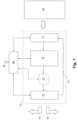
- FIG. 1 A schematic representation of a picking system 10 suitable for implementing the present invention is shown.
- the picking system 10 typically obtains the goods to be picked from a warehouse 16, which can be configured, for example, as a high-bay warehouse. However, other types of warehouses are also conceivable.
- the goods retrieved from the warehouse 16 are transported from the loading station 11 to a buffer 12, where they are temporarily stored for further order processing.
- the dispatch station 14 usually comprises a plurality of individual dispatch stations working in parallel (40 in Figure 7 ).
- the goods are assembled in such a way that one order A can be completely processed at one shipping location.
- a matrix sorter 13 can be used - especially if the goods of an order are to be presented in a specific order (in Fig. 1 and 2 (shown in dashed lines as an option), to which the goods are fed from the intermediate storage 12, and which forwards the goods in groups to the shipping locations in the shipping station 14.
- the basic structure of the picking system changes as in Figure 2
- the order picking system 10' of the Figure 2 differs from the order picking system 10 of the Figure 1
- the goods processed in the two loading stations 11a and 11b are reunited at the exit of the loading stations and then processed together in any order.
- This further processing can take place in a single buffer, but can also, as Figure 2 shows, are carried out in two parallel operating buffers 12.1 and 12.2, which then, if necessary, work again on a common matrix sorter 13 at the output.
- several complete picking lines operating in parallel can also be provided in the picking system.
- the (empty) trolleys must be returned to the loading station 11 or to the loading stations 11a and 11b for reloading after the goods have been picked up at the shipping station 14.
- the Figure 1 a return 17 is provided.
- two return lines 17a and 17b are used, which are assigned to the different loading stations 11a and 11b.
- the invention provides for a special pre-sorting of the goods in the intermediate storage 12.
- a special structure of the intermediate storage 12, or 12.1 and 12.2 serves - as explained below.
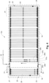
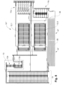
- the buffer 12a of the Figure 3 comprises a circulating conveyor 20, which in the example shown has a (essentially horizontal) rectangular basic shape with two opposite long sides (conveyor tracks 20a and 20c) and two opposite short sides (conveyor tracks 20b and 20d). As indicated by the arrows, the goods conveyed by the circulating conveyor 20 move clockwise around the rectangle on the conveyor tracks 20a-d.
- the rectangular basic shape of the circulating conveyor 20 is now divided into a first area UF1 (right) and a second area UF2 (left).
- a dynamic buffer 18 is arranged, which contains a plurality of storage sections 23, which are grouped into a total of five storage sections 21, each comprising eight parallel storage sections.
- the storage sections 23 run as right-angled branches between the conveyor section 20a and the conveyor section 20c of the circulating conveyor 20.
- Each storage section 23 has a (in Figure 3 entrance and one (in Figure 3 below) exit, so that the goods are transported in the direction indicated by the arrow (from top to bottom).
- an actuatable exit switch 22 is arranged, which, when actuated, ensures that goods conveyed on the conveyor section 20a are diverted from the conveyor section 20a into the storage section 23.
- an actuatable entry switch 24 is arranged, which, when actuated, ensures that goods are diverted from the storage section 23 into the conveyor section 20c of the circulating conveyor 20. For this purpose, it is also necessary to separate the goods on the storage section 23 before the entry switch 24 and to convey them out of the storage section 23 via the entry switch 24.
- a pre-buffer 19 is arranged, which contains a total of five parallel storage sections 26 in a group.
- the storage sections 26 run as right-angled branches between the conveyor section 20c and the conveyor section 20a of the circulating conveyor 20.
- Each storage section 26 has a (in Figure 3 entrance below and one (in Figure 3 (top) exit, so that the goods are transported therein in the direction indicated by the arrow (from bottom to top).
- the transport direction on the storage lines 26 is thus opposite to the transport direction on the storage lines 23.
- each storage section 26 there is an actuatable exit switch 25 which, when actuated, ensures that the goods transported on the conveyor section 20c Goods are diverted from the conveyor line 20c into the storage line 26.
- an actuatable entry switch 27 is arranged, which, when actuated, ensures that a piece of goods is diverted from the storage line 26 into the conveyor line 20a of the circulating conveyor 20. For this purpose, it is also necessary to separate the goods on the storage line 26 in front of the entry switch 27 and to transport them out of the storage line 26 via the entry switch 27.
- the dynamic storage 18 and the retrieval storage 19 are thus closely connected to one another in terms of transport technology via the circulating conveyor 20.
- a gap is left between the dynamic storage 18 and the retrieval storage 19, in which several conveying lines 30, 31, 32 lead away from the circulating conveyor 20 and towards the circulating conveyor 20.
- Goods arriving from the loading station 11 are fed into the circulating conveyor 20 via a feed line 30 and a corresponding entry switch and then temporarily stored in the dynamic storage 18 and its storage sections 23.
- the goods pre-sorted and stored in the retrieval storage 19 are removed from the circulating conveyor 20 via an exit switch via a discharge line 31 and forwarded to the matrix sorter 13 (or directly to the dispatch station 14).
- a further discharge line 32 with a corresponding exit switch can be used to transport empty carrier bags to the shipping station 14.
- the storage sections 23 and 26 are designed as passive gravity sections, which have a gradient from the inlet to the outlet and on which the conveyed goods (e.g. hanging on the previously mentioned carriages) move automatically due to gravity (i.e. without the intervention of a conveyor chain or the like) from the entrance to the exit.
- the conveyor section 20a in the first area UF1 of the circulating conveyor 20 is higher than the conveyor section 20c.
- the conveyor section 20c in the second area UF2 of the circulating conveyor 20 must be higher than the conveyor section 20a in order to create a counter-directional gradient.
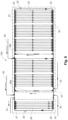
- Figure 4 shows a opposite Figure 3 A slightly modified embodiment of an intermediate storage device according to the invention.
- the difference in the intermediate storage device 12b is that instead of the single return path 28, two parallel return paths 28a and 28b are now provided, with corresponding ascending conveyors 29a and 29b and exit switches 57a and 57b, which further facilitate or accelerate the rearrangement or re-sorting of the goods on the way from the dynamic storage device 18 to the retrieval storage device 19.
- Figure 5 shows a opposite Figure 3 A slightly modified embodiment of an intermediate storage device according to the invention.
- the difference in the intermediate storage device 12c is that a return line 33 branches off from the circulating conveyor 20 before the return line 28, via which goods can be transported back from the circulating conveyor 20 to the loading station 11 if necessary.
- Figure 6 shows a opposite Figure 3 slightly modified embodiment of a buffer according to the invention.
- the difference in the buffer 12d consists in the fact that an additional return line 28c is installed in the central part of the dynamic storage 18, and a further feed line 34 is provided at this point.
- the dynamic storage 18 is divided into two partial storage areas, which can be filled separately and from which goods can be rearranged separately.
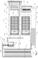
- the picking system 10 which can be designed, for example, for throughputs in the order of several thousand transport units or goods per hour, comprises a first loading station 11a with a total of six parallel loading stations 35, at each of which clothing can be loaded onto hangers for transport within the picking system ("Garment On Hanger" GOH).
- a second loading station 11b also with six loading stations 36, serves to fill goods that cannot be hung on a hanger into transport bags ("bags").
- two parallel operating intermediate storage units 12.1 and 12.2 are provided, each of which has an internal structure as shown by way of example in Figures 3 to 6.
- a matrix sorter 13 is arranged behind the intermediate storage units 12.1 and 12.2, with two successive sorting stages 13a and 13b. From the output of the matrix sorter 13, the goods reach the dispatch station 14 with a total of 28 individual, parallel working dispatch stations 40.
- the transport of the goods between the individual system sections takes place via distribution rings VR1 to VR9, with the distribution ring VR8 Order-sorted goods are brought to the individual shipping locations 40, and the distribution ring VR9 collects the empty transport vehicles for return via the empty return lines 38 and 39 to the corresponding loading stations 11a and 11b.
- An empty storage unit 37 is inserted into the empty return line 39 for the empty transport bags, in which the empty transport bags can be collected and temporarily stored.
- the distribution ring VR6 collects the pre-sorted goods from both intermediate storage units 12.1 and 12.2 and passes them on to the matrix sorter 13. It can be seen that the matrix sorter 13 can be designed very small with 5 lines each in the two sorting stages 13a and 13b due to the pre-sorting in the intermediate storage units 12.1 and 12.2.
- Distribution ring VR7 connects the two sorting stages 13a and 13b.
- Distribution ring VR4 distributes the returned empty transport devices (without the goods hanging on coat hangers) to the individual loading locations 35 of loading station 11a, while distribution ring VR3 distributes the empty transport bags to the loading locations 36 of loading station 11b.
- the transport devices filled with goods are collected by distribution rings VR1, VR2, and VR5 for input into the buffers 12.1 and 12.2.
- the goods belonging to a plurality of orders are first stored in a largely random manner in the dynamic memory of the intermediate storage devices 12.1 and 12.2, then pre-sorted by means of the retrieval memory and subsequently forwarded via the matrix sorter 13 to the transferred to the individual shipping locations 40 in the shipping station 14 so that all goods belonging to an order are present at the respective shipping location 40 in a predetermined sequence. If, in particular, a predetermined sequence is not necessary (e.g., when the order is placed by an end user), the matrix sorter can be dispensed with entirely. Pre-sorting takes place with the aid of the circulating conveyor 20 within the intermediate storage areas 12.1 and 12.2 by targeted exchange of the goods between the dynamic storage area 18 and the retrieval storage area 19, including the return lines 28 and 28a-c, respectively.
- Figure 8 shows a Figure 7 comparable embodiment with a picking system 10′′′, which differs from the picking system 10" only in that an empty storage area 37' is also planned in the empty return line 38 for the empty transport means (without the goods hanging on hangers).
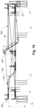
- FIGS 9 and 10 show in different subfigures different views of a buffer of the Figures 3-6 shown type, which - as already mentioned above - works with gravitational paths as storage paths.
- gradient sections 42b and 42d are installed in the short lateral conveyor sections 20b and 20d of the circulating conveyor 20 for the height change, while in the long Conveyor sections 20a and 20c between the dynamic storage 18 and the retrieval storage 19 are provided with inclined sections 42a and 42c.
- Figures 9(c) and 9(f) show the (linear) gradient of the storage sections 23 and 26, respectively, while figure 9(b) shows the return section 28 with the (necessary) inclined conveyor 29.
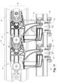
- FIG 11 shows a section of an exemplary embodiment of a circulating conveyor, as can be used in the intermediate storage 12 or 12.1, 12.2 or 12a-e.
- the circulating conveyor 20 comprises a conveyor chain 46, which is guided with its chain links 47 in a rail in the running direction or conveying direction marked with an arrow.
- a guide rail 44 is held parallel by support elements 45, in which individual carriages 50 are mounted so as to be movable in the running direction.
- the guide rail 44 with the carriages 50 is also part of the storage sections 23 and 26 in the intermediate storage areas.
- the chain links 47 of the conveyor chain 46 engage with the carriages 50 via downwardly projecting drivers 48 and 49 and a bolt-shaped engagement element 52 on the carriage 50, so that a conveying movement of the conveyor chain 46 causes a corresponding movement of the engaged carriages 50.
- a connecting element 51 is provided on each of the carriages 50, by means of which, for example, a carrying bag or a coat hanger can be suspended from the carriage 50.
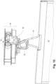
- Figure 12 shows an exemplary carriage 50 of a circulating conveyor according to Figure 11 with attached carrying bag 55.
- the carrying bag 55 hangs on a carrying handle 54, which is designed as a hanger in the middle and is an eyelet 53 on the carriage 50, which, due to its spatial shape, enables the stable hanging of the carrying bag both transversely and parallel to the longitudinal direction of the guide rail 44.
Landscapes
- Engineering & Computer Science (AREA)
- Mechanical Engineering (AREA)
- Physics & Mathematics (AREA)
- Mathematical Physics (AREA)
Claims (12)
- Installation de préparation de commandes (10, 10', 10'', 10‴) pour la préparation de commandes de différentes marchandises, en particulier de marchandises pouvant être transportées à l'état suspendu, ladite installation de préparation de commandes (10, 10', 10", 10‴) comprenant au moins une station de remplissage (11) ayant une pluralité du places de remplissage (35, 36) qui sont disposés en parallèle pour fournir les marchandises à préparer à l'installation de préparation des commandes (10, 10', 10", 10‴), ainsi qu'au moins une station d'expédition (14) comportant plusieurs places d'expédition (40) qui sont disposés en parallèle pour distribuer les marchandises préparées pour l'expédition, dans lequel au moins un stockage intermédiaire (12 ; 12.1, 12.2 ; 12a-d) est prévu pour la préparation des commandes entre la station de remplissage (11) et la station d'expédition (14), dans lequel au moins un magasin temporaire (12 ; 12.1, 12.2 ; 12a-d) comporte un magasin dynamique (18) pour le stockage temporaire des marchandises fournies pour la préparation des commandes, et un magasin de réserve (19), en aval du magasin dynamique (18), pour le stockage des marchandises qui sont extraites du magasin dynamique (18) et donc pré-triées, et qui sont disposées à l'intérieur d'un convoyeur à circulation commun (20) et reliées les unes aux autres par l'intermédiaire du convoyeur à circulation commun (20), le convoyeur à circulation (20) comportant plusieurs sections de convoyeur (20a-d), et en ce que le magasin dynamique (18) et le magasin de réserve (19) sont chacun formés par une pluralité de sections de stockage (23, 26) qui, en tant que branches, partent de sections de transport pré-définies (20a, 20c) du convoyeur à circulation (20), qui comprennent chacune une entrée et une sortie, et en ce que les sections de stockage (23, 26) par l'entrée sont chacune reliées à une première section de transport (20a, ou 20c, respectivement), et par la sortie sont dans chaque cas reliées à une deuxième section de convoyeur (20c, ou 20a, respectivement), dans laquelle les directions de transport de la première (20a respectivement 20c) et de la deuxième (20c respectivement 20a) section de convoyeur sont mutuellement opposées et dans laquelle chacune des sections de stockage (23, 26) est reliée aux sections de convoyeur associées (20a, 20c) du convoyeur à circulation (20) à l'entrée au moyen d'un aiguillage de sortie activable (22, 25) et à la sortie au moyen d'un aiguillage d'accès activable (24, 27), caractérisées en ce que les sections de stockage (23, 26) sont dans chaque cas configurées comme des sections de gravité qui comprennent une pente de l'entrée à la sortie, et sur lesquelles les marchandises transportées se déplacent en vertu de la gravité de manière autonome de l'entrée à la sortie.
- Installation de préparation de commandes selon la revendication 1, caractérisée par le fait qu'une unité de tri matriciel (13) pour un tri supplémentaire est disposée entre le magasin temporaire (12 ; 12.1, 12.2 ; 12a-d) et la station d'expédition (14).
- Installation de préparation de commandes selon la revendication 1, caractérisée par le fait que le convoyeur à circulation (20) est subdivisé en deux régions (UF1 , UF2), que le magasin dynamique (18) est disposé dans l'une des deux régions (UF1, UF2) et que le magasin de réserve (19) est disposé dans l'autre des deux régions (UF1, UF2), et par le fait que le convoyeur à circulation (20) est prévu pour transporter les marchandises du magasin dynamique (18) au magasin de réserve (18).
- Installation de préparation de commandes selon la revendication 1, caractérisée par le fait que les marchandises à préparer en vue d'un stockage temporaire et d'un pré-tri entre les deux zones (UF1, UF2) du convoyeur à circulation (20) au moyen d'une ligne d'alimentation (30) peuvent être introduites dans le convoyeur à circulation (20) et, au moyen d'une ligne de sortie (31), peuvent également être récupérées dans un état de pré-tri à partir du magasin de réserve (19).
- Installation de préparation de commandes selon la revendication 1, caractérisée par le fait qu'au moins une section de retour (18 ; 18a-c) ayant un aiguillage de sortie associé (57 ; 57a) est prévue à la sortie du magasin dynamique (18) vers le magasin de réserve (19), les marchandises en transit du magasin dynamique (18) vers le magasin de réserve (19) par le biais de ladite section de retour (18 ; 18a-c) pouvant être sélectivement transportées de la deuxième section de convoyeur (20c) vers la première section de convoyeur (20a).
- Installation de préparation de commandes selon la revendication 1, caractérisée par le fait que le convoyeur à circulation (20) comprend un convoyeur suspendu et par le fait que les marchandises à préparer dans le convoyeur à circulation (20) sont de préférence transportées de manière suspendue sur des chariots individuels (50) le long d'un rail de roulement (44), et que les chariots (50) du convoyeur à circulation (20) sont déplacés par une chaîne de convoyeur entraînée (46) qui, pour être parallèle au rail de roulement (44), est guidée dans un rail dédié (43) et qui s'engage de manière amovible avec les chariots (50).
- Installation de préparation de commandes selon la revendication 1, caractérisée par le fait que plusieurs magasins temporaires (12.1, 12.2) fonctionnant en parallèle sont prévus dans l'installation de préparation de commandes (10').
- Installation de préparation de commandes selon la revendication 6, caractérisée par le fait qu'un retour (17) des chariots (50) non chargés de marchandises de la station d'expédition (14) à la station de remplissage (11) est prévu et en ce que, de préférence, au moins un magasin vide (37, 37') pour les chariots (50) non chargés de marchandises est prévu dans le retour (17).
- Installation de préparation de commandes selon la revendication 1, caractérisée par le fait qu'un contrôleur (56) est prévu pour le fonctionnement de l'installation de préparation de commandes (10, 10', 10", 10‴), ledit contrôleur (56) assemblant les marchandises respectives par commande comme stipulé par les commandes entrantes, et dirigeant lesdites marchandises sous la forme assemblée vers les places d'expédition (40) dans la station d'expédition (14).
- Méthode d'exploitation d'une installation de préparation de commandes selon l'une des revendications 1 à 9, caractérisé par le fait que les marchandises associées à une pluralité de commandes sont d'abord stockées dans le magasin dynamique (18) d'au moins un magasin temporaire ( 12 ; 12.1, 12.2 ; 12a-d), puis pré-triées dans le magasin de réserve (19), et ensuite transférées vers les différents places d'expédition (40) dans la station d'expédition (14) de sorte que toutes les marchandises associées à une commande soient présentes à l'emplacement d'expédition respectif (40).
- Méthode selon la revendication 10, caractérisée par le fait que les marchandises sont pré-triées lorsqu'elles sont en transit entre le magasin dynamique (18) et le magasin de réserve (19), de préférence les marchandises qui doivent être pré-triées à partir du magasin dynamique (18) sont renvoyées sélectivement au magasin dynamique (18) ou acheminées vers le magasin de réserve (19).
- Méthode selon la revendication 11, caractérisé par le fait que le retour sélectif des marchandises vers le magasin dynamique (18) s'effectue au moyen d'au moins une section de retour (28 ; 28a-c) qui, au moyen d'un aiguillage de sortie contrôlable (57 ; 57a,b), est reliée au convoyeur à circulation (20).
Applications Claiming Priority (2)
| Application Number | Priority Date | Filing Date | Title |
|---|---|---|---|
| CH00947/17A CH714004A1 (de) | 2017-07-20 | 2017-07-20 | Kommissionieranlage zum Kommissionieren von unterschiedlichen, insbesondere hängend transportierbaren Waren, sowie Verfahren zum Betrieb einer solchen Kommissionieranlage. |
| PCT/EP2018/069214 WO2019016120A1 (fr) | 2017-07-20 | 2018-07-16 | Installation de préparation de commandes pour la préparation de différentes marchandises commandées pouvant en particulier être transportées en suspension, ainsi que procédé pour faire fonctionner ladite installation de préparation de commandes |
Publications (3)
| Publication Number | Publication Date |
|---|---|
| EP3655351A1 EP3655351A1 (fr) | 2020-05-27 |
| EP3655351C0 EP3655351C0 (fr) | 2025-03-12 |
| EP3655351B1 true EP3655351B1 (fr) | 2025-03-12 |
Family
ID=62986086
Family Applications (1)
| Application Number | Title | Priority Date | Filing Date |
|---|---|---|---|
| EP18743739.7A Active EP3655351B1 (fr) | 2017-07-20 | 2018-07-16 | Installation de préparation de commandes pour la préparation de différentes marchandises commandées pouvant en particulier être transportées en suspension, ainsi que procédé pour faire fonctionner ladite installation de préparation de commandes |
Country Status (5)
| Country | Link |
|---|---|
| US (1) | US10934102B2 (fr) |
| EP (1) | EP3655351B1 (fr) |
| CN (1) | CN111183102B (fr) |
| CH (1) | CH714004A1 (fr) |
| WO (1) | WO2019016120A1 (fr) |
Families Citing this family (24)
| Publication number | Priority date | Publication date | Assignee | Title |
|---|---|---|---|---|
| AT520281B1 (de) * | 2017-08-08 | 2021-12-15 | Knapp Ag | Hängefördersystem zum Sortieren von Produkten |
| CH714814A1 (de) | 2018-03-20 | 2019-09-30 | Ferag Ag | Fördervorrichtung zum Eintakten von Transporteinheiten. |
| DE102018209268A1 (de) * | 2018-06-11 | 2019-12-12 | Dürkopp Fördertechnik GmbH | Verfahren und Vorrichtung zum Erstellen von Aufträgen aus Einzelwaren |
| CH715719A1 (de) | 2019-01-09 | 2020-07-15 | Ferag Ag | Pufferspeicheranlage für Hängefördersysteme. |
| ES2961353T3 (es) | 2019-02-11 | 2024-03-11 | Tgw Logistics Group Gmbh | Sistema de almacenamiento y preparación de pedidos con prestaciones de almacenamiento mejoradas y procedimiento de funcionamiento del mismo |
| DE102019215304B3 (de) | 2019-10-04 | 2020-08-13 | Dürkopp Fördertechnik GmbH | Vorrichtung und Verfahren zum Aufgeben von Hängefördergut in eine Hängeförderanlage sowie Hängeförderanlage mit einer derartigen Vorrichtung |
| CN115812064B (zh) * | 2020-03-03 | 2026-03-10 | 詹森瑞典公司 | 服装操纵装置、传送器系统以及用于将空的服装衣架定位在个性化的安装位置中的方法 |
| CN111646084B (zh) * | 2020-06-28 | 2022-01-14 | 浙江工业大学之江学院 | 一种基于悬挂式货架的数字化柔性仓储装置及方法 |
| CN111908054B (zh) * | 2020-08-10 | 2021-08-17 | 宁波圣瑞思工业自动化有限公司 | 一种吊挂系统及控制方法 |
| WO2022198316A1 (fr) * | 2021-03-22 | 2022-09-29 | Planiform Conveyors Inc. | Système de récupération et de stockage de vêtements automatisé |
| AT525183B1 (de) | 2021-06-24 | 2023-06-15 | Tgw Logistics Group Gmbh | Verteilersystem und Verfahren zum Fördern von Waren in einem Lager- und Kommissioniersystem |
| CN115780275B (zh) * | 2021-09-10 | 2026-02-06 | 浙江衣拿智能科技股份有限公司 | 无固定货架分拣系统 |
| DE102021211484A1 (de) * | 2021-10-12 | 2023-04-13 | Dürkopp Fördertechnik GmbH | Verfahren und Anlage zum Kommissionieren und Packen von hängend geförderten Einzelwaren |
| DE102022203414B3 (de) * | 2022-04-06 | 2023-08-03 | Vanderlande Industries B.V. | Transporttasche, Traghaken, Transportvorrichtung und Hängefördersystem |
| CN114789145B (zh) * | 2022-04-21 | 2024-06-04 | 湖北普罗格科技股份有限公司 | 一种输送线结构智能拣选工作站及其拣选方法 |
| DE102022205210A1 (de) * | 2022-05-24 | 2023-11-30 | Dürkopp Fördertechnik GmbH | Förderverfahren und Fördervorrichtung für Waren mehrerer Aufträge |
| DE102022205209A1 (de) * | 2022-05-24 | 2023-11-30 | Dürkopp Fördertechnik GmbH | Fördervorrichtung und Förderverfahren für Waren |
| DE102022205211A1 (de) * | 2022-05-24 | 2023-11-30 | Dürkopp Fördertechnik GmbH | Förderverfahren und Fördervorrichtung für Waren |
| WO2024098087A1 (fr) * | 2022-11-08 | 2024-05-16 | Tgw Mechanics Gmbh | Système de préparation de commandes et procédé de préparation de commandes |
| CH720472A1 (de) | 2023-02-03 | 2024-08-15 | Ferag Ag | Abstandsoptimierungsvorrichtung für ein Fördersystem, Verfahren zur Förderung von Hängetransportelementen und Hängefördersystem |
| EP4446255B1 (fr) * | 2023-04-12 | 2025-09-24 | BEUMER Group GmbH & Co. KG | Convoyeur aérien pour assembler des articles en ordre de tri et procédé correspondant |
| CH720733A1 (de) | 2023-04-25 | 2024-10-31 | Ferag Ag | Kommissionieranlage |
| CH721462A1 (de) | 2023-12-22 | 2025-06-30 | Ferag Ag | Anlage und Verfahren zum Sortieren und Zwischenspeichern von Stückgütern |
| CN118663590B (zh) * | 2024-07-19 | 2024-11-22 | 丸三浩联科技(浙江)有限公司 | 一种净衣分配出单系统及其净衣分配出单方法 |
Family Cites Families (26)
| Publication number | Priority date | Publication date | Assignee | Title |
|---|---|---|---|---|
| US5072822A (en) * | 1990-06-20 | 1991-12-17 | Fabri-Check, Inc. | Article sorting system |
| DE4211682C2 (de) * | 1992-04-07 | 1994-03-24 | Banss Kg Maschf | Verfahren und Vorrichtung zum Zwischenlagern von Förderobjekten, insbesondere Schlachttierkörpern oder Schlachttierkörperteilen, in einer Stapelgleisanordnung |
| DE4226066A1 (de) | 1992-08-06 | 1994-02-10 | Rsl Logistik Gmbh & Co | Verfahren zum Sortieren |
| EP0627371B1 (fr) * | 1993-06-04 | 1997-12-10 | Ferag AG | Procédé pour la préparation de commandes et dispositif de mise en oeuvre de ce système |
| DE4335637C1 (de) * | 1993-10-13 | 1995-06-22 | Dietrich Prof Lux | Verfahren zum Sortieren von Einzelstücken und Sortieranlage dafür |
| DE9406061U1 (de) | 1994-04-12 | 1995-08-10 | Mts Modulare Transport Systeme Gmbh, Vomp | Sortieranlage zum Sortieren von einzeln geförderten Gegenständen |
| US6050421A (en) * | 1997-09-11 | 2000-04-18 | Jensen Usa, Inc. | Automatic laundry tie-off apparatus and method |
| JP3895443B2 (ja) * | 1997-11-26 | 2007-03-22 | 株式会社ダイフク | 自動倉庫 |
| SE516221C2 (sv) | 1999-12-23 | 2001-12-03 | Acg Nystroem Ab | Lager- och transportsystem samt transportvagn därför |
| DE10039394C1 (de) | 2000-08-11 | 2001-09-13 | Mts Modulare Transp Systeme Gm | Sortierverfahren, Sortieranlage und Sortiersystem |
| DE20103664U1 (de) | 2001-03-02 | 2001-06-13 | PEP Fördertechnik GmbH, 33609 Bielefeld | Fördersystem |
| DE10145606A1 (de) * | 2001-09-15 | 2003-04-03 | Duerkopp Adler Ag | Verfahren zum Einlagern von Fördergut-Teilen in einen Speicher und zur Ausgabe von ausgewählten Fördergut-Teilen |
| DE10149910A1 (de) * | 2001-10-10 | 2003-04-24 | Wf Logistik Gmbh | Sortiereinrichtung für insbesondere hängend gefördertes Fördergut und Verfahren zum Betrieb einer solchen |
| DE102011103194A1 (de) | 2011-05-31 | 2012-12-06 | SSI Schäfer PEEM GmbH | Verteileinrichtung und Verfahren zum Zusammenstellen einer Gruppe von Fördergütern |
| CH705451A1 (de) * | 2011-08-30 | 2013-03-15 | Ferag Ag | Verfahren, Anlage und Fördereinheit zum Bereitstellen von Gruppen von Produkten. |
| DE102012101198A1 (de) | 2011-10-11 | 2013-04-11 | Rsl Logistik Gmbh & Co. Kg | Verfahren zum Kommissionieren von Aufträgen und Hängebahnanlage |
| DE102012019717A1 (de) | 2012-10-02 | 2014-04-03 | SSI Schäfer PEEM GmbH | Fördertechnik-Anlage aus portablen Transport-Modulen |
| DE102013206240A1 (de) * | 2013-04-09 | 2014-10-09 | Dürkopp Fördertechnik GmbH | Vorrichtung und Verfahren zum auftragsorientierten Bereitstellen von Einzelwaren für mehrere Aufträge aus einem Warenlager |
| DK2886494T5 (en) * | 2013-12-23 | 2017-07-10 | Dematic Logistics Gmbh | TRANSPORTING DEVICE FOR TRANSPORTING HANGING TOPICS |
| CH710023A1 (de) | 2014-08-27 | 2016-02-29 | Ferag Ag | Förderanlage für den Transport von Gegenständen, insbesondere Waren, entlang einer vorgegebenen Strecke. |
| CH710022A1 (de) | 2014-08-27 | 2016-02-29 | Ferag Ag | Laufwagen für ein Fördersystem, insbesondere für einen Schwerkraftförderer, Fördersystem und Verfahren zum Betrieb eines Fördersystems. |
| AT14694U1 (de) | 2015-08-19 | 2016-04-15 | Knapp Ag | Kommissionierplatz zum Kommissionieren von Artikeln in Auftragsbehälter und Fördertaschen zur Auftrags- und Batchkommissionierung |
| EP3214024B1 (fr) * | 2016-03-01 | 2018-06-27 | EWAB Engineering AB | Système de transporteur autonome |
| JP6743750B2 (ja) * | 2017-04-14 | 2020-08-19 | 株式会社ダイフク | 物品搬送設備 |
| CH714814A1 (de) * | 2018-03-20 | 2019-09-30 | Ferag Ag | Fördervorrichtung zum Eintakten von Transporteinheiten. |
| DE102018219583C5 (de) * | 2018-11-15 | 2025-09-11 | Dürkopp Fördertechnik GmbH | Förderanlage und Verfahren zum Fördern von Waren |
-
2017
- 2017-07-20 CH CH00947/17A patent/CH714004A1/de unknown
-
2018
- 2018-07-16 CN CN201880047907.XA patent/CN111183102B/zh active Active
- 2018-07-16 US US16/631,792 patent/US10934102B2/en active Active
- 2018-07-16 EP EP18743739.7A patent/EP3655351B1/fr active Active
- 2018-07-16 WO PCT/EP2018/069214 patent/WO2019016120A1/fr not_active Ceased
Also Published As
| Publication number | Publication date |
|---|---|
| US10934102B2 (en) | 2021-03-02 |
| EP3655351C0 (fr) | 2025-03-12 |
| CH714004A1 (de) | 2019-01-31 |
| CN111183102A (zh) | 2020-05-19 |
| EP3655351A1 (fr) | 2020-05-27 |
| WO2019016120A1 (fr) | 2019-01-24 |
| CN111183102B (zh) | 2022-03-01 |
| US20200172346A1 (en) | 2020-06-04 |
Similar Documents
| Publication | Publication Date | Title |
|---|---|---|
| EP3655351B1 (fr) | Installation de préparation de commandes pour la préparation de différentes marchandises commandées pouvant en particulier être transportées en suspension, ainsi que procédé pour faire fonctionner ladite installation de préparation de commandes | |
| EP3592668B1 (fr) | Procédé de préparation de commandes d'articles et dispositif de préparation de commandes pour la mise en oeuvre de ce procédé | |
| DE102018114026B4 (de) | Zweistufige Kommissionierung mittels Sorter mit hochdynamischen Sorterschalen | |
| EP2714552B1 (fr) | Dispositif de distribution pour rassembler un groupe de produits transportés | |
| EP3575243B1 (fr) | Installation de préparation de commandes et procédé de fonctionnement d'une installation de préparation de commandes | |
| EP2297005B2 (fr) | Système de stockage et procédé pour le faire fonctionner | |
| EP0457158B1 (fr) | Dispositif pour rassembler et préparer des articles | |
| EP2173644B1 (fr) | Système et procédé pour manipuler des marchandises de retour dans une installation de préparation de commandes | |
| DE4335637C1 (de) | Verfahren zum Sortieren von Einzelstücken und Sortieranlage dafür | |
| DE102008036564A1 (de) | Skalierbarer Versandpuffer mit integrierter Sortierfunktion und Verfahren dazu | |
| WO2013004712A1 (fr) | Système de stockage et de préparation de commandes et procédé de préparation de commandes automatique au moyen d'un stock à canaux | |
| EP4194366B1 (fr) | Système et procédé de traitement d'une pluralité de commandes de préparation de commandes comprenant plusieurs articles | |
| AT510745A1 (de) | Kommissionierverfahren und -system | |
| DE68927706T2 (de) | Zulieferungssystem | |
| WO2024224357A1 (fr) | Système de préparation de commandes et procédé de préparation de commandes de marchandises à la pièce | |
| EP4166482A1 (fr) | Technique de transport suspendu et procédé de transport des adaptateurs de suspension, ainsi qu'installation de transport suspendu dotée d'une telle technique de transport suspendu | |
| DE1556616A1 (de) | Verfahren zum Kommissionieren unter Anwendung eines Sortierfoerderers | |
| DE102023123292B4 (de) | Hängefördersystem und Verfahren zum Betreiben eines Hängefördersystems | |
| EP4282786B1 (fr) | Dispositif et procédé de transport de marchandises | |
| DE10149910A1 (de) | Sortiereinrichtung für insbesondere hängend gefördertes Fördergut und Verfahren zum Betrieb einer solchen | |
| CH721462A1 (de) | Anlage und Verfahren zum Sortieren und Zwischenspeichern von Stückgütern |
Legal Events
| Date | Code | Title | Description |
|---|---|---|---|
| STAA | Information on the status of an ep patent application or granted ep patent |
Free format text: STATUS: UNKNOWN |
|
| STAA | Information on the status of an ep patent application or granted ep patent |
Free format text: STATUS: THE INTERNATIONAL PUBLICATION HAS BEEN MADE |
|
| PUAI | Public reference made under article 153(3) epc to a published international application that has entered the european phase |
Free format text: ORIGINAL CODE: 0009012 |
|
| STAA | Information on the status of an ep patent application or granted ep patent |
Free format text: STATUS: REQUEST FOR EXAMINATION WAS MADE |
|
| 17P | Request for examination filed |
Effective date: 20200120 |
|
| AK | Designated contracting states |
Kind code of ref document: A1 Designated state(s): AL AT BE BG CH CY CZ DE DK EE ES FI FR GB GR HR HU IE IS IT LI LT LU LV MC MK MT NL NO PL PT RO RS SE SI SK SM TR |
|
| AX | Request for extension of the european patent |
Extension state: BA ME |
|
| DAV | Request for validation of the european patent (deleted) | ||
| DAX | Request for extension of the european patent (deleted) | ||
| STAA | Information on the status of an ep patent application or granted ep patent |
Free format text: STATUS: EXAMINATION IS IN PROGRESS |
|
| 17Q | First examination report despatched |
Effective date: 20220720 |
|
| P01 | Opt-out of the competence of the unified patent court (upc) registered |
Effective date: 20230507 |
|
| REG | Reference to a national code |
Ref country code: DE Ref legal event code: R079 Free format text: PREVIOUS MAIN CLASS: B65G0037020000 Ipc: B65G0047510000 Ref country code: DE Ref legal event code: R079 Ref document number: 502018015642 Country of ref document: DE Free format text: PREVIOUS MAIN CLASS: B65G0037020000 Ipc: B65G0047510000 |
|
| GRAP | Despatch of communication of intention to grant a patent |
Free format text: ORIGINAL CODE: EPIDOSNIGR1 |
|
| STAA | Information on the status of an ep patent application or granted ep patent |
Free format text: STATUS: GRANT OF PATENT IS INTENDED |
|
| RIC1 | Information provided on ipc code assigned before grant |
Ipc: B07C 5/36 20060101ALI20240918BHEP Ipc: B65G 1/04 20060101ALI20240918BHEP Ipc: B65G 37/02 20060101ALI20240918BHEP Ipc: B65G 1/137 20060101ALI20240918BHEP Ipc: B65G 47/51 20060101AFI20240918BHEP |
|
| INTG | Intention to grant announced |
Effective date: 20241014 |
|
| GRAS | Grant fee paid |
Free format text: ORIGINAL CODE: EPIDOSNIGR3 |
|
| GRAA | (expected) grant |
Free format text: ORIGINAL CODE: 0009210 |
|
| STAA | Information on the status of an ep patent application or granted ep patent |
Free format text: STATUS: THE PATENT HAS BEEN GRANTED |
|
| AK | Designated contracting states |
Kind code of ref document: B1 Designated state(s): AL AT BE BG CH CY CZ DE DK EE ES FI FR GB GR HR HU IE IS IT LI LT LU LV MC MK MT NL NO PL PT RO RS SE SI SK SM TR |
|
| REG | Reference to a national code |
Ref country code: GB Ref legal event code: FG4D Free format text: NOT ENGLISH |
|
| REG | Reference to a national code |
Ref country code: CH Ref legal event code: EP |
|
| REG | Reference to a national code |
Ref country code: DE Ref legal event code: R096 Ref document number: 502018015642 Country of ref document: DE |
|
| REG | Reference to a national code |
Ref country code: IE Ref legal event code: FG4D Free format text: LANGUAGE OF EP DOCUMENT: GERMAN |
|
| P04 | Withdrawal of opt-out of the competence of the unified patent court (upc) registered |
Free format text: CASE NUMBER: APP_13438/2025 Effective date: 20250318 |
|
| U01 | Request for unitary effect filed |
Effective date: 20250314 |
|
| U07 | Unitary effect registered |
Designated state(s): AT BE BG DE DK EE FI FR IT LT LU LV MT NL PT RO SE SI Effective date: 20250321 |
|
| PG25 | Lapsed in a contracting state [announced via postgrant information from national office to epo] |
Ref country code: RS Free format text: LAPSE BECAUSE OF FAILURE TO SUBMIT A TRANSLATION OF THE DESCRIPTION OR TO PAY THE FEE WITHIN THE PRESCRIBED TIME-LIMIT Effective date: 20250612 |
|
| PG25 | Lapsed in a contracting state [announced via postgrant information from national office to epo] |
Ref country code: ES Free format text: LAPSE BECAUSE OF FAILURE TO SUBMIT A TRANSLATION OF THE DESCRIPTION OR TO PAY THE FEE WITHIN THE PRESCRIBED TIME-LIMIT Effective date: 20250312 |
|
| PG25 | Lapsed in a contracting state [announced via postgrant information from national office to epo] |
Ref country code: NO Free format text: LAPSE BECAUSE OF FAILURE TO SUBMIT A TRANSLATION OF THE DESCRIPTION OR TO PAY THE FEE WITHIN THE PRESCRIBED TIME-LIMIT Effective date: 20250612 |
|
| PG25 | Lapsed in a contracting state [announced via postgrant information from national office to epo] |
Ref country code: HR Free format text: LAPSE BECAUSE OF FAILURE TO SUBMIT A TRANSLATION OF THE DESCRIPTION OR TO PAY THE FEE WITHIN THE PRESCRIBED TIME-LIMIT Effective date: 20250312 |
|
| PG25 | Lapsed in a contracting state [announced via postgrant information from national office to epo] |
Ref country code: GR Free format text: LAPSE BECAUSE OF FAILURE TO SUBMIT A TRANSLATION OF THE DESCRIPTION OR TO PAY THE FEE WITHIN THE PRESCRIBED TIME-LIMIT Effective date: 20250613 |
|
| U20 | Renewal fee for the european patent with unitary effect paid |
Year of fee payment: 8 Effective date: 20250728 |
|
| PG25 | Lapsed in a contracting state [announced via postgrant information from national office to epo] |
Ref country code: SM Free format text: LAPSE BECAUSE OF FAILURE TO SUBMIT A TRANSLATION OF THE DESCRIPTION OR TO PAY THE FEE WITHIN THE PRESCRIBED TIME-LIMIT Effective date: 20250312 |
|
| PG25 | Lapsed in a contracting state [announced via postgrant information from national office to epo] |
Ref country code: PL Free format text: LAPSE BECAUSE OF FAILURE TO SUBMIT A TRANSLATION OF THE DESCRIPTION OR TO PAY THE FEE WITHIN THE PRESCRIBED TIME-LIMIT Effective date: 20250312 |
|
| PGFP | Annual fee paid to national office [announced via postgrant information from national office to epo] |
Ref country code: CH Payment date: 20250801 Year of fee payment: 8 |
|
| PG25 | Lapsed in a contracting state [announced via postgrant information from national office to epo] |
Ref country code: CZ Free format text: LAPSE BECAUSE OF FAILURE TO SUBMIT A TRANSLATION OF THE DESCRIPTION OR TO PAY THE FEE WITHIN THE PRESCRIBED TIME-LIMIT Effective date: 20250312 |
|
| PG25 | Lapsed in a contracting state [announced via postgrant information from national office to epo] |
Ref country code: SK Free format text: LAPSE BECAUSE OF FAILURE TO SUBMIT A TRANSLATION OF THE DESCRIPTION OR TO PAY THE FEE WITHIN THE PRESCRIBED TIME-LIMIT Effective date: 20250312 |
|
| PG25 | Lapsed in a contracting state [announced via postgrant information from national office to epo] |
Ref country code: IS Free format text: LAPSE BECAUSE OF FAILURE TO SUBMIT A TRANSLATION OF THE DESCRIPTION OR TO PAY THE FEE WITHIN THE PRESCRIBED TIME-LIMIT Effective date: 20250712 |
|
| PLBE | No opposition filed within time limit |
Free format text: ORIGINAL CODE: 0009261 |
|
| STAA | Information on the status of an ep patent application or granted ep patent |
Free format text: STATUS: NO OPPOSITION FILED WITHIN TIME LIMIT |
|
| REG | Reference to a national code |
Ref country code: CH Ref legal event code: L10 Free format text: ST27 STATUS EVENT CODE: U-0-0-L10-L00 (AS PROVIDED BY THE NATIONAL OFFICE) Effective date: 20260121 |
|
| 26N | No opposition filed |
Effective date: 20251215 |
|
| GBPC | Gb: european patent ceased through non-payment of renewal fee |
Effective date: 20250716 |
|
| REG | Reference to a national code |
Ref country code: CH Ref legal event code: R18 Free format text: ST27 STATUS EVENT CODE: U-0-0-R10-R18 (AS PROVIDED BY THE NATIONAL OFFICE) Effective date: 20260408 |
|
| PG25 | Lapsed in a contracting state [announced via postgrant information from national office to epo] |
Ref country code: GB Free format text: LAPSE BECAUSE OF NON-PAYMENT OF DUE FEES Effective date: 20250716 |