EP3655598B1 - Panneaux dotés d'une lèvre saillante détachable pour des revêtements destinés à être posés sur des murs, des plafonds ou des sols - Google Patents
Panneaux dotés d'une lèvre saillante détachable pour des revêtements destinés à être posés sur des murs, des plafonds ou des sols Download PDFInfo
- Publication number
- EP3655598B1 EP3655598B1 EP17742224.3A EP17742224A EP3655598B1 EP 3655598 B1 EP3655598 B1 EP 3655598B1 EP 17742224 A EP17742224 A EP 17742224A EP 3655598 B1 EP3655598 B1 EP 3655598B1
- Authority
- EP
- European Patent Office
- Prior art keywords
- panel
- protruding lip
- panels
- vertical
- horizontal locking
- Prior art date
- Legal status (The legal status is an assumption and is not a legal conclusion. Google has not performed a legal analysis and makes no representation as to the accuracy of the status listed.)
- Active
Links
Images


Classifications
-
- E—FIXED CONSTRUCTIONS
- E04—BUILDING
- E04F—FINISHING WORK ON BUILDINGS, e.g. STAIRS, FLOORS
- E04F13/00—Coverings or linings, e.g. for walls or ceilings
- E04F13/07—Coverings or linings, e.g. for walls or ceilings composed of covering or lining elements; Sub-structures therefor; Fastening means therefor
- E04F13/08—Coverings or linings, e.g. for walls or ceilings composed of covering or lining elements; Sub-structures therefor; Fastening means therefor composed of a plurality of similar covering or lining elements
- E04F13/0889—Coverings or linings, e.g. for walls or ceilings composed of covering or lining elements; Sub-structures therefor; Fastening means therefor composed of a plurality of similar covering or lining elements characterised by the joints between neighbouring elements, e.g. with joint fillings or with tongue and groove connections
- E04F13/0894—Coverings or linings, e.g. for walls or ceilings composed of covering or lining elements; Sub-structures therefor; Fastening means therefor composed of a plurality of similar covering or lining elements characterised by the joints between neighbouring elements, e.g. with joint fillings or with tongue and groove connections with tongue and groove connections
-
- E—FIXED CONSTRUCTIONS
- E04—BUILDING
- E04F—FINISHING WORK ON BUILDINGS, e.g. STAIRS, FLOORS
- E04F15/00—Flooring
- E04F15/02—Flooring or floor layers composed of a number of similar elements
- E04F15/02038—Flooring or floor layers composed of a number of similar elements characterised by tongue and groove connections between neighbouring flooring elements
-
- E—FIXED CONSTRUCTIONS
- E04—BUILDING
- E04F—FINISHING WORK ON BUILDINGS, e.g. STAIRS, FLOORS
- E04F2201/00—Joining sheets or plates or panels
- E04F2201/01—Joining sheets, plates or panels with edges in abutting relationship
- E04F2201/0138—Joining sheets, plates or panels with edges in abutting relationship by moving the sheets, plates or panels perpendicular to the main plane
- E04F2201/0146—Joining sheets, plates or panels with edges in abutting relationship by moving the sheets, plates or panels perpendicular to the main plane with snap action of the edge connectors
-
- E—FIXED CONSTRUCTIONS
- E04—BUILDING
- E04F—FINISHING WORK ON BUILDINGS, e.g. STAIRS, FLOORS
- E04F2201/00—Joining sheets or plates or panels
- E04F2201/02—Non-undercut connections, e.g. tongue and groove connections
- E04F2201/023—Non-undercut connections, e.g. tongue and groove connections with a continuous tongue or groove
-
- E—FIXED CONSTRUCTIONS
- E04—BUILDING
- E04F—FINISHING WORK ON BUILDINGS, e.g. STAIRS, FLOORS
- E04F2201/00—Joining sheets or plates or panels
- E04F2201/04—Other details of tongues or grooves
- E04F2201/041—Tongues or grooves with slits or cuts for expansion or flexibility
-
- E—FIXED CONSTRUCTIONS
- E04—BUILDING
- E04F—FINISHING WORK ON BUILDINGS, e.g. STAIRS, FLOORS
- E04F2201/00—Joining sheets or plates or panels
- E04F2201/04—Other details of tongues or grooves
- E04F2201/042—Other details of tongues or grooves with grooves positioned on the rear-side of the panel
-
- E—FIXED CONSTRUCTIONS
- E04—BUILDING
- E04F—FINISHING WORK ON BUILDINGS, e.g. STAIRS, FLOORS
- E04F2201/00—Joining sheets or plates or panels
- E04F2201/04—Other details of tongues or grooves
- E04F2201/043—Other details of tongues or grooves with tongues and grooves being formed by projecting or recessed parts of the panel layers
-
- E—FIXED CONSTRUCTIONS
- E04—BUILDING
- E04F—FINISHING WORK ON BUILDINGS, e.g. STAIRS, FLOORS
- E04F2201/00—Joining sheets or plates or panels
- E04F2201/04—Other details of tongues or grooves
- E04F2201/044—Other details of tongues or grooves with tongues or grooves comprising elements which are not manufactured in one piece with the sheets, plates or panels but which are permanently fixedly connected to the sheets, plates or panels, e.g. at the factory
-
- E—FIXED CONSTRUCTIONS
- E04—BUILDING
- E04F—FINISHING WORK ON BUILDINGS, e.g. STAIRS, FLOORS
- E04F2201/00—Joining sheets or plates or panels
- E04F2201/05—Separate connectors or inserts, e.g. pegs, pins, keys or strips
- E04F2201/0523—Separate tongues; Interlocking keys, e.g. joining mouldings of circular, square or rectangular shape
- E04F2201/0547—Separate tongues; Interlocking keys, e.g. joining mouldings of circular, square or rectangular shape adapted to be moved perpendicular to the joint edge
-
- E—FIXED CONSTRUCTIONS
- E04—BUILDING
- E04F—FINISHING WORK ON BUILDINGS, e.g. STAIRS, FLOORS
- E04F2201/00—Joining sheets or plates or panels
- E04F2201/07—Joining sheets or plates or panels with connections using a special adhesive material
-
- E—FIXED CONSTRUCTIONS
- E04—BUILDING
- E04F—FINISHING WORK ON BUILDINGS, e.g. STAIRS, FLOORS
- E04F2290/00—Specially adapted covering, lining or flooring elements not otherwise provided for
Definitions
- the present invention relates to panels with a detachable protruding lip for wall-, ceiling- or floor coverings. Furthermore, it relates to a method for manufacturing wall-, ceiling- or floor coverings comprising or consisting of a plurality of such panels.
- EP 1 282 752 A1 relates to panels of a laminate floor, comprising coupling elements which enable a form-fitting connection between the panels.
- a first and a second panel have coupling elements on one side in each case, whereby the first panel can be connected form-fittingly to the second panel by a rotary movement.
- the first and second panels additionally have on a further side in each case coupling elements which are so configured that the second panel is connectable form-fittingly to the first panel by lowering said second panel with respect to the first panel.
- the first panel includes a projecting edge positioned laterally on its underside as an additional coupling element serving to connect the panels by lowering.
- the second panel includes a projecting edge positioned laterally on its upper side and serves to connect the panels by lowering, which projecting edge projects further in comparison to lateral portions of this panel located below said projecting edge.
- the projecting edge of the second panel has on its underside a first projecting locking element which in the assembled state of the two panels engages in a corresponding first recess in the projecting edge on the underside of the first panel.
- the first recess is openly accessible when the first panel rests with its underside on a floor.
- the two panels include further coupling elements serving to connect the panels by lowering, which lock the two panels form-fittingly in a vertical direction with respect to the surface of the panels.
- the further coupling elements serving to join the panels by lowering are located below the edge projecting on the upper side.
- a plurality of gaps between the coupling elements of the first and second panels serving to connect the panels by lowering are present at the locations which are not used for mechanical connection.
- the gaps are provided between the coupling elements in such a way that no free play remains at the connecting joint between the two panels.
- WO 97/047834 A1 refers to a floor covering, consisting of hard floor panels which, at least at the edges of two opposite sides, are provided with coupling parts, cooperating with each other, substantially in the form of a tongue and a groove, characterized in that the coupling parts are provided with integrated mechanical locking means which prevent the drifting apart of two coupled floor panels into a direction perpendicular to the related edges and parallel to the underside of the coupled floor panels.
- WO 03/025307 A1 relates to floorboards for installation of floors in herringbone pattern which are formed with two opposite sides inverted relative to each other.
- WO 04/63491 A1 refers to a floor covering, of the type consisting of hard floor panels, which are manufactured of a plate material and which, at least at a number of sides, are provided with coupling parts, characterized in that the floor panels are configured such that, in joined condition, they represent a herringbone pattern, whereby the sides of the floor panels coincide with transition edges of the herringbone pattern.
- WO 01/066877 A1 relates to a vertically joined flooring material comprising floor elements with a mainly triangular, square, rectangular, rhomboidal or polygonal shape.
- the floor elements are provided with edges which are provided with joining members, a lower side and a decorative top surface.
- the flooring material comprises a combination of at least two types of floor elements, which types comprise female floor elements and male floor elements.
- the female floor element is provided with a female joining member on at least half of the number of its edges and a male joining member on less than half of the number of its edges.
- the male floor element is provided with a male joining member on at least two thirds of the number of its edges and a female joining member on less than one third of the number of its edges.
- An optional joining profile possibly constitutes a junction between two adjacent male joining members of two adjacent floor elements.
- WO2007/142589 A1 refers to a connection member for massive dynamic bodies comprising a longitudinal body having a cross section that includes two base plates aligned in opposite directions adapted to extend along the bottom sides of two adjacent dynamic bodies, wherein the base plates are provided with projections directed upwards; an upright shank with two shank legs, the shank legs transforming into the respective base plates; two spring arms extending out from the upper body of the shank essentially parallel to the base plates, wherein the spring arms are bent upwards and bent inwards towards the shank such that a lower section is essentially parallel to an upper section, each respective upper section of the spring arms being provided with a projection directed upwards; and a supporting head arranged on top of the upper body of the shank in a mounted position, and a method of connecting dynamic bodies such as wood pieces where at least two wood pieces having circumferential recesses are connected to at least one connecting member.
- US 2010/0031594 A1 relates to a hardwood floor system with press down locking mechanism.
- Each floor board is equipped with both male and female locking mechanisms.
- the male locking mechanism of a floor bard can be locked into the female locking mechanism of an adjacent floor board by simply exerting downward force on the floor board.
- the female locking mechanism is equipped with a spring slot that enables easy engagement of male and female locking mechanisms.
- EP 1 730 366 A1 refers to a panel element for laying on floors, walls and/or ceilings, comprising a rectangular basic body.
- the basic body has a first head edge, a second head edge opposed to the first head edge, a first longitudinal edge extending perpendicularly to the first head edge, and a second longitudinal edge opposed to the first longitudinal edge.
- Both head edges and both longitudinal edges are contoured so as to allow a connection with an adjacent panel element at each edge, and wherein the first longitudinal edge has a groove and the second longitudinal edge has a corresponding tongue.
- a shorter upper leg and longer lower leg are provided on the first longitudinal edge, wherein the contours of the head edges each have an undercut so as to allow an engagement of the tongue of the second longitudinal edge in the contour of each head edge of an adjacent, identical panel element.
- a step is provided on each head edge adjoining the undercut and an engagement facility is provided between the lower leg of the first longitudinal edge and the step so as to allow a connection between the groove of the first longitudinal edge and each head edge of an adjacent, identical panel element.
- DE 19601 322 A1 discloses a panel according to the preamble of claim 1. It is directed to an assembly that involves boards which have at the back at least one rebate set along a long or transverse side. Connecting tongues are placed in the groove formed by the rebates of two adjoining boards so that the latter are connected together. The tongues can be stuck in by hot sealing adhesive.
- the connecting tongue has on its top side at least one spigot strip running along a long side to engage in a guide groove provided in the rebate of one board.
- the tongues can be made of wood or plastics.
- WO 2015/155312 A1 is describes a construction and methods of assembly and construction of boards, e.g. floor boards, are described.
- the boards have a peripheral connection arrangement for interconnecting of one board to another, a core layer e.g. made from a wood or fibre based material and a top layer applied to the core layer which may be decorative and may include or provide a wear layer.
- a further bottom layer may be applied to the underside of the core layer and is designed to be in contact with the floor or an underlay can be applied when in use.
- the connection arrangement includes interconnecting hooking tongues and corresponding catches which co-operate to produce both vertical and horizontal locking.
- EP 1 279 778 A2 is directed to a panel that comprises a first projecting profile at one edge.
- the profile is open towards the top and has an undercut.
- the panel further comprises a second profile which has projecting lug on its opposite edge.
- the lug is open towards the bottom and engages the same profile in the undercut.
- At least one of the profiles is elastically yielding in its longitudinal direction.
- EP 1 650 375 A1 describes floor panels which are provided with a mechanical locking system consisting of a flexible tongue in a sliding groove which during a vertical folding motion is displaced. Moreover, a tongue blank, a production method and an installation method are shown.
- the panel elements known in the prior art have the disadvantage that especially for herringbone patterns they provide little or no locking at all in a vertical direction away from laying the plane. Often locking systems are employed on rather thin panels, so that complicated machining of delicate profile elements with many undercuts is difficult and expensive and delicate locking elements are often damaged and deformed, especially when they are used for flooring.
- the objective of the present invention was the provision of a panel with a locking system which is stable in locking, simple to manufacture with only a low risk for damaging the locking elements, allows for easy and interesting installations and allows laying any desired pattern.
- This objective is achieved by the panel for wall-, ceiling- or floor coverings according to claim 1.
- This panel comprises an upper side, a lower side, and front ends, defining a circumference of the panel in the installed state and at least one front is protruded with respect to the circumference by a detachable protruding lip formed at the lower side, wherein the panel further comprises one horizontal locking groove at the lower side.
- At least two detachable protruding lips are fixed at the panel at opposite sides of the panel, the protruding lip has a predetermined break-off surface, and the protruding lip comprises at least one horizontal locking element, being suitable for engaging in the horizontal locking groove (6) of a neighbored panel, when the protruding lip (5) of said neighbored panel has been removed.
- Claim 12 of the present invention further relates to a method for manufacturing wall-, ceiling- and/or floor coverings comprising or consisting of a plurality of panels according to the present invention.
- a first panel at its front end is connected with the corresponding front end of the neighbored panel by removing the protruding lip at the predetermined break-off surface and by joining the protruding lip of the first panel with the neighbored panel.
- Claims 13 and 14 relate to preferred embodiments of said method.
- claim 15 of the present invention relates to a further method for manufacturing wall-, ceiling- and/or floor coverings comprising or consisting of a plurality of panels according to one of claims 1 to 3.
- an adhesive or a glue is provided onto at least a part of the surface of the protruding lip for providing a locking function in the vertical direction or the adhesive or a glue is provided onto at least a part of the front end.
- panels are rectangular and have a regular shape.
- regular shapes have sides that are all equal and interior (inside) angles that are all equal, whereas irregular shapes have sides and angles of any length and size.
- the invention is not limited to rectangular panels having a regular shape, but the inventive concept is also applicable to panels having an irregular shape.
- the predetermined break-off surface is formed by one or more start notches, one or more cuttings, preferably laser cuttings, one or more drillings, one or more milled slots, a density gradient within the panel, by means of introducing a film, adhesives, binders and/or primers and/or by using different materials in the area of the predetermined break-off surface.
- the protruding lip comprises at least one horizontal locking element, being suitable for engaging in the horizontal locking groove of a neighbored panel, when the protruding lip of said neighbored panel has been removed.
- a horizontal locking element according to the present invention has a locking effect in horizontal direction, whereas a vertical locking element has a locking effect in vertical direction.
- the horizontal direction is the laying direction of the panels and the vertical direction is the direction at right angle to the laying direction.
- At least two detachable protruding lips are fixed at the panel at opposite sides of the panel.
- the panel has four sides and is rectangular and protruding lips are fixed at all four sides of the panel.
- all front ends are protruded with respect to the circumference by a detachable protruding lip formed at the lower side.
- the horizontal locking element additionally retains the neighbored panel in vertical and/or horizontal direction.
- a vertical locking groove is incorporated in the front end.
- the vertical looking groove can accommodate vertical locking means.
- MDF medium density fiber board
- HDF high density fiber board
- cork high density fiber board
- OSB oriented strand board
- solid wood plywood
- PVC polyvinylidene chloride
- the panel consists of laminate floorboards made of MDF or HDF or PVC or mixtures thereof.
- PVC polyvinyl styrene
- the PVC is free of softeners.
- the front end comprises at the upper side a vertical locking groove over the whole length of the front end or at least over parts of the length of the front end.
- a further preferred embodiment envisages that a vertical looking groove is formed at the horizontal locking element.
- the protruding lip comprises a trough.
- Said embodiment is in particular preferred when joining is carried out by applying an adhesive or a glue.
- the trough is suitable for the accommodation of the adhesive or the glue and since the user can dose the amount of the adhesive or glue, oozing of said adhesive or glue oozes over the edges during the joining process is prevented. Furthermore, it is possible to fix a double-sided adhesive in the trough during the manufacturing process of the protruding lip.
- the predetermined break-off surface is formed by one start notch and one end notch. Said embodiment is in particular preferred when the panel with the protruding lip both consists of MDF or HDF.
- the one end notch is preferably arranged in the horizontal locking groove.
- the panel has a rectangular shape.
- the length of the panel is an integer multiple of the width, such as 1:1, 1:2, 1:3, 1:4, 1:5, 1:6, 1:7, 1:8, 1:9, 1:10, 1:11, 1:12 etc., preferably 1:6.
- a herringbone pattern cannot be obtained.
- the protruding lip comprises a trough, more preferably said through comprises a double-sided adhesive tape.
- the protruding lip and the core of the panel consist of different materials.
- Cheap materials like e.g. plastics are preferred for the protruding lip.
- the protruding lip comprises, preferably consists of a material selected from the group consisting of MDF, HDF or plastics and the core comprises, preferably consists of a material selected from the group consisting of MDF, HDF or plastics, preferably PVC more preferably the protruding lip consists of plastic and the core consists of MDF or HDF or PVC or mixtures thereof.
- Another preferred embodiment of the present invention envisages that the bend surface of the protruding lip is beveled. This embodiment has the advantage that the risk of damaging the panel during the laying process is reduced.
- start notch is oriented in a vertical distance in the range from 0,1 to 10 mm above the upper lip surface for forming a crack gap.
- Said crack gap can accommodate any irregular break off surface.
- a decorative layer and/ or an abrasion resistant layer is arranged on the upper side.
- a layer for insulating footstep sounds and/or a counterdraw layer is oriented below the lower side. More preferably the panel comprises an abrasion resistant layer, a decorative layer, a counterdraw laver and a layer for insulating footstep sounds.
- the protruding lip can in principle be fixed to the panel by all fixing techniques known in the arts, preferably by gluing or adhering.
- the present invention further relates to two methods for manufacturing wall-, ceiling- and/or floor coverings comprising or consisting of a plurality of panels according to claim 1.
- the locking function in vertical direction is achieved by mechanical means, whereas no mechanical means are required for locking in vertical direction by the second method.
- the protruding lip of the first panel comprises at least one horizontal locking element being suitable for engagement in the horizontal locking groove of the neighbored panel, whose protruding lip has been removed, wherein during joining the horizontal locking groove is incorporated in the horizontal locking groove.
- the first panel and the neighbored panel each have a vertical locking groove at their front end and during joining an insertable locking element connecting the vertical locking grooves is introduced in the vertical locking grooves.
- the protruding lip preferably comprises a trough for the accommodation of an adhesive or the through comprises a double-sided adhesive tape.
- the laying pattern Independent on the method chosen for laying the panel, there is no limitation regarding the laying pattern. Both methods allow laying the panels parallels to each other or laying the panels vertically to each other, as needed for herringbone patterns or other complex patterns.
- Figure 1 shows a side view of a cut off panel (1), focusing on the locking system according to the present invention.
- a horizontal locking element (9) is mounted on a protruding lip (5).
- the horizontal locking element is designed in such a way, that it fits into a horizontal locking groove (6) of a neighboring panel (1') and thereby provides locking in a horizontal direction.
- the panel (1) has an upper side (2), which may or may not be decorated or covered by an additional abrasion resistant surface. Furthermore, the panel (1) may or may not have a decorative bevel (20) at its edge. With the embodiment shown in Figure 1 , a start notch (8) is created in the panel (1).
- Figure 2 shows another side view of a cut off panel (1) according to the invention.
- Figure 2 shows how the protruding lip (5) with the horizontal locking element (9) is detached from the panel (1) along a predetermined break off surface (7, 7').
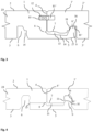
- Figure 3 shows a side view of two panels (1, 1') which are now joined together.
- the horizontal locking element (9) on the protruding lip (5) of a first panel (1) is fitted into the horizontal locking groove (6') of a second panel (1') and thereby prevents any movement in the horizontal direction.
- the protruding lip (5) of the second panel (1') has been removed by detachment along the predetermined break off surface (7) in order to achieve said horizontal locking.
- vertical locking is simultaneously achieved in several ways: Firstly, vertical locking against a movement of both panels (1,1') towards the lower side of the panels (3,3') is prevented by the substrate onto which the panels (1,1') are mounted, which is the floor, the wall, the ceiling or any further coverings thereof.
- an insertable locking element (12) is provided which is inserted into the vertical locking grooves (10,10') of both panels (1,1').
- This insertable locking element (12) together with the locking grooves (10,10') prevent vertical movement of both panels in both vertical directions, towards the lower sides (3,3') and the upper sides (2,2').
- the insertable locking element may either be inserted into the right groove by the person installing the panels, or by being pre-mounted in the factory.
- the predetermined break-off surface (7) is always a smooth and straight, perfect surface.
- panel materials such as e.g. wood based fiber boards known as MDF/HDF laminate
- a generally irregular break-off surface (7) is rather to be expected.
- the geometry of the break off surface (7) can only be predetermined within limits. This is why it is important to choose the start notch (8) at some vertical distance above the upper lip surface (14). By this measure, a crack gap (13) is achieved, which can accommodate any irregular break off surface (7).
- abutment surfaces (16,16') are intended to touch in the horizontal plane and not the upper lip surface (14) somewhere at the irregular break off surface (7), as this would result in panels which have their respective upper sides (2,2') in different planes thereby resulting in an irregular paneled surface. It is also important to add a well defined end notch surface (15) into which the crack will exit because it enables the crack to travel the shortest available distance.
- a slightly inclined contact surface (18) is chosen, which enables horizontal locking.
- the inclination of the locking surface (18) enables to pull two panels (1,1') towards each other in the final laying stage and is chosen to be 40 to 80 degrees to laying plane.
- a further inclined surface on the horizontal locking element (9) between the locking surface (18) and the abutment surface (16) additionally also serves as a guiding surface (19) to help to align the panels during laying.
- the thickness of the protruding lip (5) is carefully chosen and a further inclined bend surface (17) is added below the horizontal locking element (9) so that when a second panel (1') is joined by generally pushing it downward, the protruding lip (5) can be elastically deformed to some degree, thereby providing a slight snapping action which further holds the panels together.
- FIG. 4 shows a side view of two cut off panels (1, 1') joined by an alternative embodiment of the locking system according to the invention.
- vertical locking is achieved by a vertical locking element (11) which interacts with a vertical locking groove (10) on the horizontal locking element (9).
- a vertical locking element (11) which interacts with a vertical locking groove (10) on the horizontal locking element (9).
- Such a solution can be chosen e.g. for ceramic panels or tiles with a protruding lip (5) made of a plastic material.
- Figure 5 shows a side view of a panel (1) with another alternative embodiment of the locking system according to the invention.
- no mechanical means are provided for locking in the vertical direction away from the laying plane.
- an adhesive or a glue may be provided onto the upper lip surface to provide the locking function in the vertical direction away from the laying plane.
Landscapes
- Engineering & Computer Science (AREA)
- Architecture (AREA)
- Civil Engineering (AREA)
- Structural Engineering (AREA)
- Floor Finish (AREA)
- Finishing Walls (AREA)
- Panels For Use In Building Construction (AREA)
Claims (15)
- Panneau (1) pour revêtements de mur, de plafond ou de sol, comprenantun côté supérieur (2), un côté inférieur (3) et des extrémités avant (4), définissant une circonférence du panneau à l'état installé, etau moins une extrémité avant (4) est en saillie par rapport à la circonférence par l'intermédiaire d'une lèvre en saillie amovible (5) formée au niveau du côté inférieur (3),une rainure de verrouillage horizontale (6) étant prévue sur le côté inférieur (3),caractérisé en ce que,au moins deux lèvres en saillie amovibles (5) sont fixées au niveau du panneau (1) sur des côtés opposés du panneau (1),les lèvres en saillie (5) présentant une surface de rupture prédéterminée (7), etles lèvres en saillie (5) comprenant au moins un élément de verrouillage horizontal (9), étant adapté pour venir en prise dans la rainure de verrouillage horizontale (6) d'un panneau voisin (1'), lorsque la lèvre en saillie (5) dudit panneau voisin (1') a été retirée.
- Panneau (1) selon la revendication 1, caractérisé en ce que la surface de rupture prédéterminée (7) est formée par une ou plusieurs encoches de départ (8), une ou plusieurs découpes, de préférence des découpes au laser, un ou plusieurs perçages, une ou plusieurs fentes fraisées, un gradient de densité à l'intérieur du panneau (1), au moyen de l'introduction d'un film, d'adhésifs, de liants et/ou d'apprêts et/ou en utilisant différents matériaux dans la zone de la surface de rupture prédéterminée (7).
- Panneau (1) selon l'une quelconque des revendications précédentes, caractérisé en ce que l'élément de verrouillage horizontal (9) retient le panneau voisin (1') dans la direction verticale et/ou horizontale.
- Panneau (1) selon l'une quelconque des revendications précédentes, caractérisé en ce quetoutes les extrémités avant (4) sont en saillie par rapport à la circonférence par l'intermédiaire d'une lèvre en saillie amovible (5) formée au niveau du côté inférieur (3) et/ouune rainure de verrouillage verticale (10) est incorporée dans l'extrémité avant (4).
- Panneau (1) selon l'une quelconque des revendications précédentes, caractérisé en ce que le panneau (1) comprend, de préférence, un matériau choisi dans le groupe comprenant MDF, HDF, liège, OSB, bois massif, contreplaqué, plastiques, de préférence le PVC, fibres de ciment, basalte, laine de roche, céramique, pierre véritable, métal, de préférence un panneau d'aluminium ou d'acier, verre, plastiques, panneaux de particules, panneaux de plancher stratifiés et des mélanges ou appariements de ceux-ci.
- Panneau (1) selon l'une quelconque des revendications précédentes, caractérisé en ce que l'extrémité avant (4) comprend à proximité du côté supérieur (2) une rainure de verrouillage verticale (10) sur toute la longueur de l'extrémité avant (4) ou au moins sur des parties de la longueur de l'extrémité avant (4).
- Panneau (1) selon l'une quelconque des revendications 3 à 4, caractérisé en ce qu'une rainure de verrouillage verticale (10) est formée au niveau de l'élément de verrouillage horizontal (9), de préférence ladite rainure de recherche verticale (10) peut recevoir des moyens de verrouillage verticaux.
- Panneau (1) selon l'une quelconque des revendications précédentes, caractérisé en ce que le panneau (1) présente une forme rectangulaire, de préférence la longueur du panneau est un multiple entier de la largeur, de manière plus préférée le rapport entre la longueur et la largeur est de 1:1, 1:2, 1:3, 1:4, 1:5, 1:6, 1:7, 1:8, 1:9, 1:10, 1:11 ou 1:12, de la manière la plus préférée le rapport entre la longueur et la largeur est de 1:6.
- Panneau (1) selon l'une quelconque des revendications précédentes, caractérisé en ce que la lèvre en saillie (5) comprend une rigole, de préférence ladite rigole comprend un ruban adhésif double face.
- Panneau (1) selon l'une quelconque des revendications précédentes, caractérisé en ce quela surface de rupture prédéterminée (7) est formée par une encoche de départ (8) et une encoche de fin (15), dans lequel la certaine encoche de fin (15) est de préférence agencée dans la rainure de verrouillage horizontale (6) et/oula lèvre en saillie (5) comprend, de préférence est constituée d'un matériau choisi dans le groupe comprenant MDF, HDF ou des plastiques, et le noyau (23) comprend, de préférence est constitué d'un matériau choisi dans le groupe comprenant MDF, HDF ou des plastiques, de préférence le PVC, de manière plus préférée la lèvre en saillie (5) est constituée de plastique et le noyau (23) est constitué de MDF ou de HDF ou de PVC, ou de mélanges de ceux-ci, et/oula lèvre en saillie (5) comprend une surface fléchie inclinée (17) ajoutée sous l'élément de verrouillage horizontal (9) de sorte que lorsqu'un second panneau (1') est joint en le poussant généralement vers le bas, la lèvre en saillie (5) peut être déformée élastiquement dans une certaine mesure, fournissant ainsi une légère action d'encliquetage qui maintient davantage les panneaux ensemble et/oul'encoche de départ (8) est orientée dans une distance verticale dans la plage de 0,1 à 10 mm au-dessus de la surface de lèvre supérieure (14) pour former un espace de fissure (13).
- Panneau (1) selon l'une quelconque des revendications précédentes, caractérisé en ce queune couche décorative et/ou une couche résistante à l'abrasion est disposée sur la face supérieure (2), et/ouune couche d'isolation des bruits de pas et/ou une couche de contre-dépouille est orientée sous le côté inférieur (3).
- Procédé de fabrication de revêtements de mur, de plafond et/ou de sol comprenant ou consistant en une pluralité de panneaux (1) selon l'une quelconque des revendications précédentes, dans lequel un premier panneau (1) au niveau de son extrémité avant (4) est connecté à l'extrémité avant correspondante (4') du panneau voisin (1') en retirant la lèvre en saillie (5') au niveau de la surface de rupture prédéterminée (7) et en joignant la lèvre en saillie (5) du premier panneau (1) au panneau voisin (1').
- Procédé selon la revendication précédente, caractérisé en ce que la lèvre en saillie (5) du premier panneau (1) comprend au moins un élément de verrouillage horizontal (9) approprié pour venir en prise dans la rainure de verrouillage horizontale (6) du panneau voisin (1'), dont la lèvre en saillie a été retirée, dans lequel lors de la jonction, l'élément de verrouillage horizontal (9) est incorporé dans la rainure de verrouillage horizontale (6').
- Procédé selon l'une quelconque des revendications précédentes, caractérisé en ce quele premier panneau (1) et le panneau voisin (1') présentent chacun une rainure de verrouillage verticale (10, 10') au niveau de leur extrémité avant (4, 4') et avant jonction un élément de verrouillage insérable (12) reliant les rainures de verrouillage verticales (10, 10') est introduit dans les rainures de verrouillage verticales (10, 10'), et/oudes moyens adhésifs sont prévus pour un verrouillage dans la direction verticale.
- Procédé de fabrication de revêtements de mur, de plafond et/ou de sol comprenant ou consistant en une pluralité de panneaux (1) selon l'une quelconque des revendications 1 ou 3, dans lequel un adhésif ou une colle est prévu(e) sur au moins une partie de la surface de la lèvre en saillie (5) pour fournir une fonction de verrouillage dans la direction verticale, ou l'adhésif ou une colle est prévu(e) sur au moins une partie de l'extrémité avant (4).
Priority Applications (4)
| Application Number | Priority Date | Filing Date | Title |
|---|---|---|---|
| RS20250495A RS66815B1 (sr) | 2017-07-18 | 2017-07-18 | Paneli sa odvojivim isturenim obodom za zidne, plafonske ili podne obloge |
| HRP20250625TT HRP20250625T1 (hr) | 2017-07-18 | 2017-07-18 | Paneli s odvojivim izbočenim obodom za zidne, plafonske ili podne obloge |
| PL17742224.3T PL3655598T3 (pl) | 2017-07-18 | 2017-07-18 | Panele z odłączalną wystającą krawędzią na pokrycia ścienne, sufitowe lub podłogowe |
| HUE17742224A HUE071513T2 (hu) | 2017-07-18 | 2017-07-18 | Panelek eltávolítható kiálló peremmel fal-mennyezet- vagy padló-burkolatokhoz |
Applications Claiming Priority (1)
| Application Number | Priority Date | Filing Date | Title |
|---|---|---|---|
| PCT/EP2017/068140 WO2019015746A1 (fr) | 2017-07-18 | 2017-07-18 | Panneaux dotés d'une lèvre saillante détachable pour des revêtements destinés à être posés sur des murs, des plafonds ou des sols |
Publications (3)
| Publication Number | Publication Date |
|---|---|
| EP3655598A1 EP3655598A1 (fr) | 2020-05-27 |
| EP3655598C0 EP3655598C0 (fr) | 2025-04-23 |
| EP3655598B1 true EP3655598B1 (fr) | 2025-04-23 |
Family
ID=59381278
Family Applications (1)
| Application Number | Title | Priority Date | Filing Date |
|---|---|---|---|
| EP17742224.3A Active EP3655598B1 (fr) | 2017-07-18 | 2017-07-18 | Panneaux dotés d'une lèvre saillante détachable pour des revêtements destinés à être posés sur des murs, des plafonds ou des sols |
Country Status (12)
| Country | Link |
|---|---|
| US (1) | US11459774B2 (fr) |
| EP (1) | EP3655598B1 (fr) |
| CN (1) | CN110998041B (fr) |
| CA (1) | CA3069478C (fr) |
| ES (1) | ES3027196T3 (fr) |
| HR (1) | HRP20250625T1 (fr) |
| HU (1) | HUE071513T2 (fr) |
| PL (1) | PL3655598T3 (fr) |
| RS (1) | RS66815B1 (fr) |
| RU (1) | RU2731495C1 (fr) |
| UA (1) | UA125235C2 (fr) |
| WO (1) | WO2019015746A1 (fr) |
Families Citing this family (7)
| Publication number | Priority date | Publication date | Assignee | Title |
|---|---|---|---|---|
| WO2021011983A1 (fr) * | 2019-07-24 | 2021-01-28 | S.D. Sullivan Holdings Pty Ltd | Élément en mosaïque et procédé |
| DE202020006057U1 (de) * | 2019-09-25 | 2024-08-20 | Välinge Innovation AB | Paneel mit Verriegelungsvorrichtung |
| EP4034733B1 (fr) * | 2019-09-25 | 2026-02-25 | Välinge Innovation AB | Ensemble de panneaux comprenant une rainure de flexion |
| DE202019005364U1 (de) | 2019-11-07 | 2020-05-13 | Xylo Technologies Ag | Paneele mit einer abtrennbaren vorstehenden Lippe für Wand-, Decken- und Bodenverkleidungen |
| PL4055236T3 (pl) * | 2019-11-07 | 2023-11-06 | Lignum Technologies Ag | Panele z odłączalną wystającą krawędzią do pokryć ściennych, sufitowych lub podłogowych |
| PL437615A1 (pl) * | 2021-04-19 | 2022-10-24 | BARLINEK Spółka Akcyjna | Złącze paneli podłogowych |
| US12546121B1 (en) * | 2024-11-07 | 2026-02-10 | Clyx Bv | Wall panel or floor panel having locking means which are suitable for multiple profiles |
Family Cites Families (45)
| Publication number | Priority date | Publication date | Assignee | Title |
|---|---|---|---|---|
| US3538660A (en) * | 1967-11-27 | 1970-11-10 | Karl Moor | Prefabricated wall assembly for partitions and the like |
| SE501014C2 (sv) * | 1993-05-10 | 1994-10-17 | Tony Pervan | Fog för tunna flytande hårda golv |
| US7131242B2 (en) * | 1995-03-07 | 2006-11-07 | Pergo (Europe) Ab | Flooring panel or wall panel and use thereof |
| SE9500810D0 (sv) * | 1995-03-07 | 1995-03-07 | Perstorp Flooring Ab | Golvplatta |
| US6421970B1 (en) * | 1995-03-07 | 2002-07-23 | Perstorp Flooring Ab | Flooring panel or wall panel and use thereof |
| BR7502683U (pt) * | 1995-11-24 | 1996-04-09 | Jacob Abrahams | Disposiçoes construtivas em junçoes de réguas para pisos lambrís ou forros |
| GB9624901D0 (en) | 1995-12-05 | 1997-01-15 | Sico Inc | Portable floor |
| BE1010487A6 (nl) | 1996-06-11 | 1998-10-06 | Unilin Beheer Bv | Vloerbekleding bestaande uit harde vloerpanelen en werkwijze voor het vervaardigen van dergelijke vloerpanelen. |
| SE512313E (sv) * | 1998-06-03 | 2004-03-16 | Valinge Aluminium Ab | Låssystem samt golvskiva |
| IL129834A (en) * | 1999-05-06 | 2001-09-13 | Ackerstein Ind Ltd | Ground surface cover system with flexible interlocking joint for erosion control |
| SE522860C2 (sv) | 2000-03-10 | 2004-03-09 | Pergo Europ Ab | Vertikalt förenade golvelement innefattande en kombination av olika golvelement |
| DE20008708U1 (de) * | 2000-05-16 | 2000-09-14 | Kronospan Technical Co. Ltd., Nikosia | Paneele mit Kupplungsmitteln |
| DE20112474U1 (de) * | 2001-07-28 | 2002-12-19 | M. Kaindl, Wals | Paneel, beispielsweise für Fußboden-, Wand- und/oder Deckenverkleidungen |
| SE525558C2 (sv) | 2001-09-20 | 2005-03-08 | Vaelinge Innovation Ab | System för bildande av en golvbeläggning, sats av golvskivor samt förfarande för tillverkning av två olika typer av golvskivor |
| JP4472355B2 (ja) | 2002-04-03 | 2010-06-02 | ベーリンゲ、イノベイション、アクチボラグ | フロアボード用機械式係止システム |
| SE525657C2 (sv) * | 2002-04-08 | 2005-03-29 | Vaelinge Innovation Ab | Golvskivor för flytande golv framställda av åtminstone två olika materialskikt samt halvfabrikat för tillverkning av golvskivor |
| US8850769B2 (en) * | 2002-04-15 | 2014-10-07 | Valinge Innovation Ab | Floorboards for floating floors |
| WO2004063491A1 (fr) | 2003-01-08 | 2004-07-29 | Flooring Industries Ltd. | Dalle de sol, procedes de pose et de fabrication associes |
| DE102004028757B4 (de) | 2004-04-02 | 2007-11-15 | hülsta-werke Hüls GmbH & Co. KG. | Paneelelement zur Boden-, Wand- und/oder Deckenverlegung sowie Verfahren zum Verlegen eines Belages, insbesondere eines Boden-, Wand- und/oder Deckenbelages |
| SE527570C2 (sv) * | 2004-10-05 | 2006-04-11 | Vaelinge Innovation Ab | Anordning och metod för ytbehandling av skivformat ämne samt golvskiva |
| SI1650375T2 (sl) | 2004-10-22 | 2011-04-29 | Vaelinge Innovation Ab | Set talnih panelov |
| DE102006011887A1 (de) * | 2006-01-13 | 2007-07-19 | Akzenta Paneele + Profile Gmbh | Sperrelement, Paneel mit separatem Sperrelement, Verfahren zur Installation eines Paneelbelags aus Paneelen mit Sperrelementen sowie Verfahren und Vorrichtung zur Vormontage eines Sperrelements an einem Paneel |
| SE529506C2 (sv) * | 2006-02-03 | 2007-08-28 | Pergo Europ Ab | Ett fogskydd för paneler |
| SE530048C2 (sv) | 2006-06-09 | 2008-02-19 | Burseryd Innovation Ab | Fästelement samt metod att sammanfoga dynamiska kroppar medelst fästelementet |
| DE102006037614B3 (de) | 2006-08-10 | 2007-12-20 | Guido Schulte | Fußbodenbelag und Verlegeverfahren |
| DE102006057491A1 (de) * | 2006-12-06 | 2008-06-12 | Akzenta Paneele + Profile Gmbh | Paneel sowie Bodenbelag |
| US7726088B2 (en) * | 2007-07-20 | 2010-06-01 | Moritz Andre Muehlebach | Flooring system |
| DE102007042250B4 (de) * | 2007-09-06 | 2010-04-22 | Flooring Technologies Ltd. | Einrichtung zur Verbindung und Verriegelung zweier Bauplatten, insbesondere Fussbodenpaneele |
| US8029880B2 (en) * | 2008-04-24 | 2011-10-04 | Liu David C | Water resistant wide flooring boards |
| US8037656B2 (en) | 2008-08-08 | 2011-10-18 | Liu David C | Flooring boards with press down locking mechanism |
| BE1018627A5 (nl) * | 2009-01-16 | 2011-05-03 | Flooring Ind Ltd Sarl | Vloerpaneel. |
| BE1018728A3 (nl) * | 2009-04-22 | 2011-07-05 | Flooring Ind Ltd Sarl | Vloerpaneel. |
| NL2003019C2 (nl) * | 2009-06-12 | 2010-12-15 | 4Sight Innovation Bv | Vloerpaneel en vloerbedekking bestaande uit meerdere van dergelijke vloerpanelen. |
| EP3702549B1 (fr) * | 2010-01-12 | 2023-05-10 | Välinge Innovation AB | Jeu de panneaux de sol |
| CN104831904B (zh) * | 2010-05-10 | 2017-05-24 | 佩尔戈(欧洲)股份公司 | 地板组件 |
| DE102010063976B4 (de) * | 2010-12-22 | 2013-01-17 | Akzenta Paneele + Profile Gmbh | Paneel |
| DE202011110452U1 (de) * | 2011-01-28 | 2014-02-11 | Akzenta Paneele + Profile Gmbh | Paneel |
| SG193535A1 (en) | 2011-03-18 | 2013-10-30 | Inotec Internat Pty Ltd | Vertical joint system and associated surface covering system |
| EP3460142B1 (fr) | 2011-08-15 | 2020-09-30 | Ceraloc Innovation AB | Système de verrouillage mécanique pour panneaux de plancher |
| PT3115161T (pt) * | 2011-08-29 | 2020-02-06 | Ceraloc Innovation Ab | Sistema de encaixe mecânico para painéis de pavimento |
| BE1022209B1 (nl) * | 2012-01-12 | 2016-03-01 | I.V.C. N.V. | Vloerpaneel |
| WO2014033628A1 (fr) * | 2012-08-27 | 2014-03-06 | Pergo (Europe) Ab | Panneau |
| US9260870B2 (en) * | 2014-03-24 | 2016-02-16 | Ivc N.V. | Set of mutually lockable panels |
| WO2015144726A1 (fr) | 2014-03-24 | 2015-10-01 | Ivc N.V. | Ensemble de panneaux mutuellement verrouillables |
| ES2822958T3 (es) * | 2014-04-10 | 2021-05-05 | Berryalloc Nv | Tablero de piso con sistema de conexión universal |
-
2017
- 2017-07-18 HU HUE17742224A patent/HUE071513T2/hu unknown
- 2017-07-18 RS RS20250495A patent/RS66815B1/sr unknown
- 2017-07-18 ES ES17742224T patent/ES3027196T3/es active Active
- 2017-07-18 US US16/632,151 patent/US11459774B2/en active Active
- 2017-07-18 UA UAA202000327A patent/UA125235C2/uk unknown
- 2017-07-18 EP EP17742224.3A patent/EP3655598B1/fr active Active
- 2017-07-18 RU RU2020102049A patent/RU2731495C1/ru active
- 2017-07-18 CA CA3069478A patent/CA3069478C/fr active Active
- 2017-07-18 HR HRP20250625TT patent/HRP20250625T1/hr unknown
- 2017-07-18 CN CN201780093317.6A patent/CN110998041B/zh active Active
- 2017-07-18 PL PL17742224.3T patent/PL3655598T3/pl unknown
- 2017-07-18 WO PCT/EP2017/068140 patent/WO2019015746A1/fr not_active Ceased
Also Published As
| Publication number | Publication date |
|---|---|
| ES3027196T3 (en) | 2025-06-13 |
| EP3655598C0 (fr) | 2025-04-23 |
| HRP20250625T1 (hr) | 2025-07-18 |
| RU2731495C1 (ru) | 2020-09-03 |
| EP3655598A1 (fr) | 2020-05-27 |
| HUE071513T2 (hu) | 2025-09-28 |
| CN110998041B (zh) | 2022-08-16 |
| US11459774B2 (en) | 2022-10-04 |
| US20200232225A1 (en) | 2020-07-23 |
| UA125235C2 (uk) | 2022-02-02 |
| RS66815B1 (sr) | 2025-06-30 |
| PL3655598T3 (pl) | 2025-07-14 |
| WO2019015746A1 (fr) | 2019-01-24 |
| CN110998041A (zh) | 2020-04-10 |
| CA3069478C (fr) | 2023-08-01 |
| CA3069478A1 (fr) | 2019-01-24 |
Similar Documents
| Publication | Publication Date | Title |
|---|---|---|
| EP3655598B1 (fr) | Panneaux dotés d'une lèvre saillante détachable pour des revêtements destinés à être posés sur des murs, des plafonds ou des sols | |
| US11428014B2 (en) | Mechanical locking system for floor panels | |
| US10697187B2 (en) | Mechanical locking system for floor panels | |
| EP4055236B1 (fr) | Panneaux pourvus d'une lèvre saillante détachable pour revêtements muraux, de plafond ou de sol | |
| US10975577B2 (en) | Mechanical locking of floor panels with a flexible tongue | |
| US9725912B2 (en) | Mechanical locking system for floor panels | |
| CN101238261B (zh) | 用于设有滑动锁的地板面板的机械锁定系统、安装方法和生产方法 | |
| CN103649437B (zh) | 用于地板镶板的机械锁定系统 | |
| PL210099B1 (pl) | Podłoga | |
| EA043364B1 (ru) | Панели с выполненной с возможностью отделения выступающей закраиной для настенных, потолочных или напольных покрытий |
Legal Events
| Date | Code | Title | Description |
|---|---|---|---|
| REG | Reference to a national code |
Ref country code: HR Ref legal event code: TUEP Ref document number: P20250625T Country of ref document: HR |
|
| STAA | Information on the status of an ep patent application or granted ep patent |
Free format text: STATUS: UNKNOWN |
|
| STAA | Information on the status of an ep patent application or granted ep patent |
Free format text: STATUS: THE INTERNATIONAL PUBLICATION HAS BEEN MADE |
|
| PUAI | Public reference made under article 153(3) epc to a published international application that has entered the european phase |
Free format text: ORIGINAL CODE: 0009012 |
|
| STAA | Information on the status of an ep patent application or granted ep patent |
Free format text: STATUS: REQUEST FOR EXAMINATION WAS MADE |
|
| 17P | Request for examination filed |
Effective date: 20200210 |
|
| AK | Designated contracting states |
Kind code of ref document: A1 Designated state(s): AL AT BE BG CH CY CZ DE DK EE ES FI FR GB GR HR HU IE IS IT LI LT LU LV MC MK MT NL NO PL PT RO RS SE SI SK SM TR |
|
| AX | Request for extension of the european patent |
Extension state: BA ME |
|
| DAV | Request for validation of the european patent (deleted) | ||
| DAX | Request for extension of the european patent (deleted) | ||
| STAA | Information on the status of an ep patent application or granted ep patent |
Free format text: STATUS: EXAMINATION IS IN PROGRESS |
|
| 17Q | First examination report despatched |
Effective date: 20230203 |
|
| RAP3 | Party data changed (applicant data changed or rights of an application transferred) |
Owner name: LIGNUM TECHNOLOGIES AG |
|
| GRAP | Despatch of communication of intention to grant a patent |
Free format text: ORIGINAL CODE: EPIDOSNIGR1 |
|
| STAA | Information on the status of an ep patent application or granted ep patent |
Free format text: STATUS: GRANT OF PATENT IS INTENDED |
|
| INTG | Intention to grant announced |
Effective date: 20241120 |
|
| GRAS | Grant fee paid |
Free format text: ORIGINAL CODE: EPIDOSNIGR3 |
|
| GRAA | (expected) grant |
Free format text: ORIGINAL CODE: 0009210 |
|
| STAA | Information on the status of an ep patent application or granted ep patent |
Free format text: STATUS: THE PATENT HAS BEEN GRANTED |
|
| AK | Designated contracting states |
Kind code of ref document: B1 Designated state(s): AL AT BE BG CH CY CZ DE DK EE ES FI FR GB GR HR HU IE IS IT LI LT LU LV MC MK MT NL NO PL PT RO RS SE SI SK SM TR |
|
| REG | Reference to a national code |
Ref country code: GB Ref legal event code: FG4D |
|
| REG | Reference to a national code |
Ref country code: CH Ref legal event code: EP |
|
| REG | Reference to a national code |
Ref country code: DE Ref legal event code: R096 Ref document number: 602017089044 Country of ref document: DE |
|
| REG | Reference to a national code |
Ref country code: IE Ref legal event code: FG4D |
|
| REG | Reference to a national code |
Ref country code: ES Ref legal event code: FG2A Ref document number: 3027196 Country of ref document: ES Kind code of ref document: T3 Effective date: 20250613 |
|
| U01 | Request for unitary effect filed |
Effective date: 20250513 |
|
| U07 | Unitary effect registered |
Designated state(s): AT BE BG DE DK EE FI FR IT LT LU LV MT NL PT RO SE SI Effective date: 20250602 |
|
| PGFP | Annual fee paid to national office [announced via postgrant information from national office to epo] |
Ref country code: PL Payment date: 20250624 Year of fee payment: 9 |
|
| U20 | Renewal fee for the european patent with unitary effect paid |
Year of fee payment: 9 Effective date: 20250602 |
|
| PGFP | Annual fee paid to national office [announced via postgrant information from national office to epo] |
Ref country code: RS Payment date: 20250627 Year of fee payment: 9 |
|
| REG | Reference to a national code |
Ref country code: HR Ref legal event code: T1PR Ref document number: P20250625 Country of ref document: HR |
|
| PGFP | Annual fee paid to national office [announced via postgrant information from national office to epo] |
Ref country code: SK Payment date: 20250630 Year of fee payment: 9 |
|
| REG | Reference to a national code |
Ref country code: SK Ref legal event code: T3 Ref document number: E 46527 Country of ref document: SK |
|
| REG | Reference to a national code |
Ref country code: HR Ref legal event code: ODRP Ref document number: P20250625 Country of ref document: HR Payment date: 20250627 Year of fee payment: 9 |
|
| PGFP | Annual fee paid to national office [announced via postgrant information from national office to epo] |
Ref country code: HU Payment date: 20250709 Year of fee payment: 9 |
|
| REG | Reference to a national code |
Ref country code: HU Ref legal event code: AG4A Ref document number: E071513 Country of ref document: HU |
|
| PGFP | Annual fee paid to national office [announced via postgrant information from national office to epo] |
Ref country code: ES Payment date: 20250821 Year of fee payment: 9 |
|
| PG25 | Lapsed in a contracting state [announced via postgrant information from national office to epo] |
Ref country code: GR Free format text: LAPSE BECAUSE OF FAILURE TO SUBMIT A TRANSLATION OF THE DESCRIPTION OR TO PAY THE FEE WITHIN THE PRESCRIBED TIME-LIMIT Effective date: 20250724 |
|
| PGFP | Annual fee paid to national office [announced via postgrant information from national office to epo] |
Ref country code: NO Payment date: 20250718 Year of fee payment: 9 |
|
| PGFP | Annual fee paid to national office [announced via postgrant information from national office to epo] |
Ref country code: TR Payment date: 20250701 Year of fee payment: 9 |
|
| PGFP | Annual fee paid to national office [announced via postgrant information from national office to epo] |
Ref country code: GB Payment date: 20250722 Year of fee payment: 9 |
|
| PGFP | Annual fee paid to national office [announced via postgrant information from national office to epo] |
Ref country code: HR Payment date: 20250702 Year of fee payment: 9 |
|
| PGFP | Annual fee paid to national office [announced via postgrant information from national office to epo] |
Ref country code: CZ Payment date: 20250701 Year of fee payment: 9 |
|
| PG25 | Lapsed in a contracting state [announced via postgrant information from national office to epo] |
Ref country code: IS Free format text: LAPSE BECAUSE OF FAILURE TO SUBMIT A TRANSLATION OF THE DESCRIPTION OR TO PAY THE FEE WITHIN THE PRESCRIBED TIME-LIMIT Effective date: 20250823 |
|
| PG25 | Lapsed in a contracting state [announced via postgrant information from national office to epo] |
Ref country code: SM Free format text: LAPSE BECAUSE OF FAILURE TO SUBMIT A TRANSLATION OF THE DESCRIPTION OR TO PAY THE FEE WITHIN THE PRESCRIBED TIME-LIMIT Effective date: 20250423 |
|
| REG | Reference to a national code |
Ref country code: CH Ref legal event code: H13 Free format text: ST27 STATUS EVENT CODE: U-0-0-H10-H13 (AS PROVIDED BY THE NATIONAL OFFICE) Effective date: 20260224 |
|
| PLBE | No opposition filed within time limit |
Free format text: ORIGINAL CODE: 0009261 |
|
| STAA | Information on the status of an ep patent application or granted ep patent |
Free format text: STATUS: NO OPPOSITION FILED WITHIN TIME LIMIT |
|
| REG | Reference to a national code |
Ref country code: CH Ref legal event code: L10 Free format text: ST27 STATUS EVENT CODE: U-0-0-L10-L00 (AS PROVIDED BY THE NATIONAL OFFICE) Effective date: 20260304 |
|
| 26N | No opposition filed |
Effective date: 20260126 |