EP3656484A1 - Vorrichtung zum verändern der höhe einer gussform, kastenlose formmaschine und verfahren zum verändern der höhe einer gussform - Google Patents
Vorrichtung zum verändern der höhe einer gussform, kastenlose formmaschine und verfahren zum verändern der höhe einer gussform Download PDFInfo
- Publication number
- EP3656484A1 EP3656484A1 EP18834651.4A EP18834651A EP3656484A1 EP 3656484 A1 EP3656484 A1 EP 3656484A1 EP 18834651 A EP18834651 A EP 18834651A EP 3656484 A1 EP3656484 A1 EP 3656484A1
- Authority
- EP
- European Patent Office
- Prior art keywords
- filling frame
- cylinder
- flask
- squeeze board
- squeeze
- Prior art date
- Legal status (The legal status is an assumption and is not a legal conclusion. Google has not performed a legal analysis and makes no representation as to the accuracy of the status listed.)
- Withdrawn
Links
Images


Classifications
-
- B—PERFORMING OPERATIONS; TRANSPORTING
- B22—CASTING; POWDER METALLURGY
- B22C—FOUNDRY MOULDING
- B22C11/00—Moulding machines characterised by the relative arrangement of the parts of same
- B22C11/10—Moulding machines characterised by the relative arrangement of the parts of same with one or more flasks forming part of the machine, from which only the sand moulds made by compacting are removed
-
- B—PERFORMING OPERATIONS; TRANSPORTING
- B22—CASTING; POWDER METALLURGY
- B22C—FOUNDRY MOULDING
- B22C11/00—Moulding machines characterised by the relative arrangement of the parts of same
-
- B—PERFORMING OPERATIONS; TRANSPORTING
- B22—CASTING; POWDER METALLURGY
- B22C—FOUNDRY MOULDING
- B22C11/00—Moulding machines characterised by the relative arrangement of the parts of same
- B22C11/02—Machines in which the moulds are moved during a cycle of successive operations
-
- B—PERFORMING OPERATIONS; TRANSPORTING
- B22—CASTING; POWDER METALLURGY
- B22C—FOUNDRY MOULDING
- B22C15/00—Moulding machines characterised by the compacting mechanism; Accessories therefor
- B22C15/02—Compacting by pressing devices only
-
- B—PERFORMING OPERATIONS; TRANSPORTING
- B22—CASTING; POWDER METALLURGY
- B22C—FOUNDRY MOULDING
- B22C15/00—Moulding machines characterised by the compacting mechanism; Accessories therefor
- B22C15/02—Compacting by pressing devices only
- B22C15/08—Compacting by pressing devices only involving pneumatic or hydraulic mechanisms
-
- B—PERFORMING OPERATIONS; TRANSPORTING
- B22—CASTING; POWDER METALLURGY
- B22C—FOUNDRY MOULDING
- B22C15/00—Moulding machines characterised by the compacting mechanism; Accessories therefor
- B22C15/28—Compacting by different means acting simultaneously or successively, e.g. preliminary blowing and finally pressing
-
- B—PERFORMING OPERATIONS; TRANSPORTING
- B22—CASTING; POWDER METALLURGY
- B22C—FOUNDRY MOULDING
- B22C19/00—Components or accessories for moulding machines
- B22C19/04—Controlling devices specially designed for moulding machines
-
- B—PERFORMING OPERATIONS; TRANSPORTING
- B22—CASTING; POWDER METALLURGY
- B22C—FOUNDRY MOULDING
- B22C11/00—Moulding machines characterised by the relative arrangement of the parts of same
- B22C11/02—Machines in which the moulds are moved during a cycle of successive operations
- B22C11/04—Machines in which the moulds are moved during a cycle of successive operations by a horizontal rotary table or carrier
-
- B—PERFORMING OPERATIONS; TRANSPORTING
- B22—CASTING; POWDER METALLURGY
- B22C—FOUNDRY MOULDING
- B22C9/00—Moulds or cores; Moulding processes
- B22C9/02—Sand moulds or like moulds for shaped castings
Definitions
- the present disclosure relates to a mold height changing unit, a flaskless molding machine, and a mold height changing method.
- Patent Document 1 discloses a flaskless molding machine that forms a flaskless type mold that does not have any flask.
- the molding machine includes paired of an upper flask and a lower flask that clamp a match plate where a model is disposed, a filling frame, a supply mechanism that supplies molding sand, and a squeezing mechanism that compresses the molding sand.
- the molding machine moves the lower flask the filling frame close to the upper flask, and causes the upper flask and the lower flask to clamp the match plate.
- the molding machine operates the supply mechanism to supply the molding sand into upper and lower molding spaces formed by the upper flask, the lower flask, and the filling frame.
- the molding machine operates the squeezing mechanism to compress the molding sand in the upper and lower molding spaces.
- the upper mold and the lower mold are formed at the same time through the above-described processes.
- Patent Document 1 Japanese Patent No. 5168743
- the flaskless molding machine according to Patent Document 1 can form a mold with only one type of a height (thickness). If the mold height can be changed depending on a height of a product, it is possible to optimize a usage of the molding sand. Therefore, in this technical field, it is desirable to provide a mold height changing unit, a flaskless molding machine, and a mold height changing method that each can change the mold height.
- a mold height changing unit used in a flaskless molding machine includes an upper flask, a lower flask capable of clamping a match plate with the upper flask, a filling frame connectable to the lower flask, a first squeeze board movable into and out from the upper flask, a second squeeze board movable into and out from the filling frame, a filling frame cylinder moving the filling frame relative to the second squeeze board, a squeeze cylinder integrally moving the filling frame, the second squeeze board, and the filling frame cylinder, and a control unit configured to control the filling frame cylinder and the squeeze cylinder.
- the mold height changing unit includes a stopper limiting a stroke length of the filling frame cylinder to a predetermined length.
- the second squeeze board and the filling frame cylinder are integrally operated. Further, the stroke length of the filling frame cylinder is limited to the predetermined length by the stopper.
- the stroke length of the filling frame cylinder is limited by the stopper, a raised distance of the filling frame with respect to the second squeeze board (movable distance of filling frame toward lower flask) is reduced. Therefore, as compared with a case where the stroke length of the filling frame cylinder is not limited, a height of a molding space for a lower mold defined by the match plate, the lower flask, the filling frame, and the second squeeze board is reduced. As a result, a mold with a low height is formed as compared with the case where the stroke length of the filling frame cylinder is not limited.
- the mold height changing unit can change the mold height with use of the stopper.
- the stopper may include a rod member and a contact member.
- the rod member includes a first end part and a second end part, and the first end part is fixed to the filling frame and is inserted into a through hole provided in a frame supporting the filling frame cylinder.
- the contact member is attached to the second end part of the rod member and abuts on the frame when the filling frame is moved in a direction separating from the frame.
- the rod member is raised together with the filling frame. Further, when the filling frame is raised by the length of the rod member or more, the contact member attached to the second end part of the rod member abuts on the frame. As described above, the stopper can limit the stroke length of the filling frame cylinder to the predetermined length through contact of the contact member with the frame.
- a length from the frame to the contact member of the rod member when the filling frame is located at a position closest to the frame may be shorter than the stroke length of the filling frame cylinder.
- the stopper can limit the stroke length.
- the filling frame cylinder may be an air cylinder. It is difficult for the air cylinder to accurately stand on the way of the stroke.
- the mold height changing unit can cause the air cylinder to accurately stand with use of the stopper member even on the way of the stroke of the air cylinder.
- the mold height changing unit may include a position detection sensor connected to the control unit.
- the position detection sensor detects that the filling frame cylinder has been expanded to the predetermined length.
- the position detection sensor can detect that the filling frame has been moved to a position limited by the stopper.
- the mold height changing unit may include a spacer member attached to a principle surface of the first squeeze board facing the match plate. In such a configuration, a height of a molding space for an upper mold defined by the match plate, the upper flask, and the first squeeze board is reduced. As a result, as compared with a case where the spacer member is not provided, the mold with a low height is formed. As described above, the mold height changing unit can change the mold height.
- a material of the spacer member may be a resin. In such a configuration, the spacer member that is hardly deformed and is easily attached is provided.
- the spacer member may be fixed to the first squeeze board by a screw.
- the spacer member is fixable by the screw, which enables a worker to easily adjust the mold height.
- the spacer member may be fixed to the first squeeze board with use of a liner attachment screw hole provided in the first squeeze board. In such a configuration, the worker can attach the spacer member without modifying the flaskless molding machine.
- a flaskless molding machine includes an upper flask, a lower flask capable of clamping a match plate with the upper flask, a filling frame connectable to the lower flask, a first squeeze board movable into and out from the upper flask, a second squeeze board movable into and out from the filling frame, a filling frame cylinder moving the filling frame relative to the second squeeze board, a squeeze cylinder integrally moving the filling frame, the second squeeze board, and the filling frame cylinder, a control unit configured to control the filling frame cylinder and the squeeze cylinder, and a stopper limiting a stroke length of the filling frame cylinder to a predetermined length.
- the second squeeze board and the filling frame cylinder are integrally operated. Further, the stroke length of the filling frame cylinder is limited to the predetermined length by the stopper.
- the stroke length of the filling frame cylinder is limited by the stopper, a raised distance of the filling frame with respect to the second squeeze board (movable distance of filling frame toward lower flask) is reduced. Therefore, as compared with a case where the stroke length of the filling frame cylinder is not limited, a height of a molding space for a lower mold defined by the match plate, the lower flask, the filling frame, and the second squeeze board is reduced. As a result, a mold with a low height is formed as compared with the case where the stroke length of the filling frame cylinder is not limited. As described above, the flaskless molding machine can change the mold height.
- the stopper may include a rod member and a contact member.
- the rod member includes a first end part and a second end part, and the first end part is fixed to the filling frame and is inserted into a through hole provided in a frame supporting the filling frame cylinder.
- the contact member is attached to the second end part of the rod member and abuts on the frame when the filling frame is moved in a direction separating from the frame.
- the rod member is raised together with the filling frame. Further, when the filling frame is raised by the length of the rod member or more, the contact member attached to the second end part of the rod member abuts on the frame. As described above, the stopper can limit the stroke length of the filling frame cylinder to the predetermined length through contact of the contact member with the frame.
- a length from the frame to the contact member of the rod member when the filling frame is located at a position closest to the frame may be shorter than the stroke length of the filling frame cylinder.
- the stopper can limit the stroke length.
- the filling frame cylinder may be an air cylinder. It is difficult for the air cylinder to accurately stand on the way of the stroke.
- the mold height changing unit can cause the air cylinder to accurately stand with use of the stopper member even on the way of the stroke of the air cylinder.
- the flaskless molding machine may include a position detection sensor connected to the control unit.
- the position detection sensor detects that the filling frame cylinder has been expanded to the predetermined length.
- the position detection sensor can detect that the filling frame has been moved to a position limited by the stopper.
- the flaskless molding machine may include a spacer member attached to a principle surface of the first squeeze board facing the match plate.
- a height of a molding space for an upper mold defined by the match plate, the upper flask, and the first squeeze board is reduced.
- the mold height changing unit can change the mold height.
- a material of the spacer member may be a resin. In such a configuration, the spacer member that is hardly deformed and is easily attached is provided.
- the spacer member may be fixed to the first squeeze board by a screw.
- the spacer member is fixable by the screw, which enables a worker to easily adjust the mold height.
- the spacer member may be fixed to the first squeeze board with use of a liner attachment screw hole provided in the first squeeze board. In such a configuration, the worker can attach the spacer member without modifying the flaskless molding machine.
- the flaskless molding machine may include an input unit connected to the control unit.
- the input unit allows for selection of one of a first mode in which a mold is formed without limiting the stroke length of the filling frame cylinder and a second mode in which a mold is formed while the stroke length of the filling frame cylinder is limited by the stopper.
- the input unit can receive mode switching operation by the worker.
- the mold in the second mode, may be formed by further using a spacer member attached to a principle surface of the first squeeze board facing the match plate. As described above, in the second mode, thicknesses of both of the upper mold and the lower mold may be reduced.
- a flaskless molding machine includes an upper flask, a lower flask capable of clamping a match plate with the upper flask, a filling frame connectable to the lower flask, a first squeeze board movable into and out from the upper flask, a second squeeze board movable into and out from the filling frame, a filling frame cylinder moving the filling frame relative to the second squeeze board, a squeeze cylinder integrally moving the filling frame, the second squeeze board, and the filling frame cylinder, a control unit configured to control the filling frame cylinder and the squeeze cylinder, a first position detection sensor connected to the control unit and detecting that the filling frame cylinder has been expanded to a first length, and a second position detection sensor connected to the control unit and detecting that the filling frame cylinder has been expanded to a second length shorter than the first length.
- the control unit is configured to switch a mode between a first operation mode in which the filling frame cylinder is operated to be expanded up to the first length based on a result detected by the first position detection sensor and a second operation mode in which the filling frame cylinder is operated to be expanded up to the second length based on a result detected by the second position detection sensor.
- the first position detection sensor detects that the filling frame cylinder has been expanded to the first length
- the second position detection sensor detects that the filling frame cylinder has been expanded to the second length.
- the control unit switches the mode between the first mode in which the filling frame cylinder is operated to be expanded up to the first length and the second mode in which the filling frame cylinder is operated to be expanded up to the second length.
- the flaskless molding machine can change the mold height with use of the position detection sensors.
- a mold height changing method for a flaskless molding machine includes an upper flask, a lower flask capable of clamping a match plate with the upper flask, a filling frame connectable to the lower flask, a first squeeze board movable into and out from the upper flask, a second squeeze board movable into and out from the filling frame, a first filling frame cylinder moving the filling frame relative to the second squeeze board, and a squeeze cylinder integrally moving the filling frame, the second squeeze board, and the filling frame cylinder.
- the mold height changing method includes preparing a second filling frame cylinder having a stroke length different from a stroke length of the first filling frame cylinder, and replacing the first filling frame cylinder with the second filling frame cylinder.
- the second filling frame cylinder that has the stroke length different from the stroke length of the first filling frame cylinder is previously prepared. Further, the mold height can be changed by replacing the first filling frame cylinder with the second filling frame cylinder.
- a mold height changing method for a flaskless molding machine includes an upper flask, a lower flask capable of clamping a match plate with the upper flask, a filling frame connectable to the lower flask, a first squeeze board movable into and out from the upper flask, a second squeeze board movable into and out from the filling frame, a first filling frame cylinder moving the filling frame relative to the second squeeze board, and a squeeze cylinder integrally moving the filling frame, the second squeeze board, and the filling frame cylinder.
- the mold height changing method includes any one of attaching a spacer member on a principle surface of the first squeeze board facing the match plate, attaching a spacer member on a principle surface on side opposed to the principle surface of the first squeeze board facing the match plate, and replacing the first squeeze board with a third squeeze board having a thickness different from a thickness of the first squeeze board.
- the mold height can be changed by attaching the spacer member on the first squeeze board or by replacing the first squeeze board with the third squeeze board that has the thickness different from the thickness of the first squeeze board.
- the mold height changing unit, the flaskless molding machine, and the mold height changing method that each can change the mold height are provided.
- a horizontal direction corresponds to a direction of an X axis and a Y axis
- a vertical direction top-bottom direction
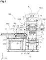
- FIG. 1 is a front view illustrating an example of a flaskless molding machine according to the embodiment.
- a flaskless molding machine 100 is a molding machine that forms a flaskless upper mold and a flaskless lower mold.
- the flaskless molding machine 100 includes a molding unit 100A that forms a mold consisting of an upper mold and a lower mold, a lower flask advance/retract driving unit 100B that advances and retracts the lower flask to/from the molding unit 100A, a mold pushing unit 100C that pushes out the mold formed by the molding unit 100A to outside, and a molding-sand supply unit 100D that supplies molding sand to the molding unit 100A.
- a box-shaped upper flask and a filling frame that are operable in the top-bottom direction (Z-axis direction) are disposed in the molding unit 100A.
- the lower flask advance/retract driving unit 100B introduces a match plate on which a model is disposed and the lower flask, into a space between the upper flask and the filling frame of the molding unit 100A.
- the upper flask, the lower flask, and the filling frame of the molding unit 100A are moved to be close to one another, and the upper flask and the lower flask clamp the match plate.
- the molding-sand supply unit 100D fills the upper flask, the lower flask, and the filling frame with the molding sand.
- the molding sand filled in the upper flask, the lower flask, and the filling frame is pressurized in the top-bottom direction by a squeezing mechanism provided in the molding unit 100A.
- a squeezing mechanism provided in the molding unit 100A.
- the upper mold and the lower mold are formed at the same time.
- the upper mold is drawn from the upper flask
- the lower mold is drawn from the lower flask and the filling frame
- the upper mold and the lower mold are conveyed to the outside of the machine by the mold pushing unit 100C.
- the flaskless molding machine 100 forms the flaskless upper mold and the flaskless lower mold in the above-described manner.
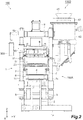
- FIG 2 is a side view illustrating the machine in Figure 1 .
- the flaskless molding machine 100 includes a portal frame 1.
- the portal frame 1 is formed by integrally coupling a lower base frame 1a and an upper frame 1b with columns 1c located therebetween at four corners in a plan view. A position surrounded by the columns 1c is also referred to as a "molding position".
- Figure 3 is a schematic enlarged view illustrating a vicinity of a lower squeeze board of the machine illustrated in Figure 1 .
- a flask set squeeze cylinder 2 (example of squeeze cylinder) is attached to be directed upward at a center part on a top surface of the lower base frame 1a.
- a lower squeeze board 4 (example of second squeeze board) is attached at a front end of a piston rod 2a of the flask set squeeze cylinder 2 with an upper end part 3a of a lower squeeze frame 3 located therebetween.
- the lower squeeze board 4 is a plate member that is configured to be movable into and out from a lower filling frame, and seals and squeezes the molding sand filled in a lower molding space of the lower flask and the filling frame.
- a main body portion 2b of the flask set squeeze cylinder 2 is inserted into an insertion hole 3c that is provided at a center of a lower end part 3b of the lower squeeze frame 3.
- Sliding bushes (not illustrated) each having a height of 10 mm or more may be provided at respective four corners of a plane of the lower base frame 1a to maintain a horizontal state of the lower squeeze frame 3.
- each of the lower filling frame cylinders 5 is an air cylinder.
- Each of the lower filling frame cylinders 5 may be a hydraulic cylinder or an electric cylinder.
- Piston rods 5a on upper side of the respective lower filling frame cylinders 5 pass through, for example, respective insertion holes 3d provided at the lower end part 3b of the lower squeeze frame 3, and the lower filling frame 6 (example of filling frame) is attached to front ends of the respective piston rods 5a.
- the lower filling frame 6 is a box-shaped frame having an open upper end and an open lower end, and the lower end is connectable to a lower end of the lower flask described below.
- An inner surface 6a of the lower filling frame 6 is formed in a tapered shape such that an internal space of the lower filling frame 6 becomes narrow as it goes downward.
- the lower squeeze board 4 can be fitted into the lower filling frame 6 while maintaining an airtight state.
- a molding-sand introduction hole 6c is provided in a side-wall part 6b of the lower filling frame 6.
- Positioning pins 7 are provided on a top surface of the lower filling frame 6.
- the lower squeeze board 4 is attached to the front end of the piston rod 2a of the flask set squeeze cylinder 2 with the upper end part 3a of the lower squeeze frame 3 located therebetween, the lower filling frame cylinders 5 are attached to the lower end part 3b of the lower squeeze frame 3, and the lower filling frame 6 is attached to the front ends of the piston rods 5a on the upper side of the respective lower filling frame cylinders 5.
- the lower squeeze board 4, the lower squeeze frame 3, the lower filling frame cylinders 5, and the lower filling frame 6 are integrally raised or lowered at the same time when the piston rod 2a of the flask set squeeze cylinder 2 is operated to expand and contract.
- the lower filling frame 6 is raised and lowered relative to the lower squeeze board 4.
- the lower filling frame 6 can be raised and lowered independently of the lower squeeze board 4 at the same time.
- the lower filling frame 6 can be raised and lowered with the lower squeeze board 4 at the same time when the lower squeeze board 4 is raised and lowered by the flask set squeeze cylinder 2.
- an original position (initial position) of the lower filling frame 6 that is vertically movable is a lowered end.
- the lower squeeze board 4 when the lower squeeze board 4 is moved upward relative to the lower filling frame 6 that is moved upward, the lower squeeze board 4 is moved to a predetermined position inside the lower filling frame 6, and forms a molding space (sand filling space) with the lower flask 23.
- the lower squeeze board 4 is moved upward relative to the lower filling frame 6, thereby performing squeezing operation and returning to the original position.
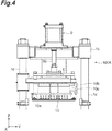
- FIG 4 is a schematic enlarged view illustrating a vicinity of an upper flask cylinder of the machine illustrated in Figure 1 .
- an upper squeeze board 8 (example of first squeeze board) is provided and fixed to a bottom surface of the upper frame 1b, and the upper squeeze board 8 is located at a position facing the lower squeeze board 4 from above.
- the upper squeeze board 8 is a plate member that is configured to be movable into and out from the upper flask and seals and squeezes the molding sand filled in an upper molding space of the upper flask.
- An upper flask cylinder 9 consisting of an air cylinder is fixed to the upper frame 1b to be directed downward.
- An upper flask 10 is attached to a front end of a piston rod 9a of the upper flask cylinder 9.
- the upper flask 10 is a box-shaped flask having an open upper end and an open lower end.
- An inner surface 10a of the upper flask 10 is formed in a tapered shape such that an internal space of the upper flask 10 becomes wide as it goes downward.
- the upper squeeze board 8 can be fitted into the upper flask 10 while maintaining an airtight state.
- a molding-sand introduction hole 10c is provided in a side-wall part 10b of the upper flask 10.
- a space S to which the lower flask 23 described below can enter and in which the entered lower flask 23 can be raised and lowered is provided at an intermediate position between the upper squeeze board 8 and the lower squeeze board 4.
- Paired travelling rails 11 that extend in parallel in a lateral direction (lateral direction is defined based on state illustrated in Figure 1 , same hereinafter) on the same horizontal plane are laid inside the columns 1c.
- the lower flask advance/retract driving unit 100B is disposed on side (negative X direction in embodiment illustrated in Figure 1 ) of the columns 1c.
- the lower flask advance/retract driving unit 100B includes a pattern shuttle cylinder 21.
- the pattern shuttle cylinder 21 is a cylinder that advances and retracts the match plate including patterns on a top side and a bottom side to the molding position and a standby position.
- a master plate 22 is horizontally attached to a front end of a piston rod 21a of the pattern shuttle cylinder 21.
- the master plate 22 is attached to the front end of the piston rod 21a in such a way as to be separable upward from the front end of the piston rod 21a.
- the lower flask 23 is attached to a bottom surface of the master plate 22.
- the lower flask 23 is a box-shaped flask that can clamp the match plate with the upper flask, and has an open upper end and an open lower end.
- a match plate 24 including a model on each of a top surface and a bottom surface is attached to a top surface of the master plate 22.
- the match plate 24 is a plate member including models on respective surfaces of a pattern plate.
- the master plate 22 includes roller arms 22a that are vertically provided at respective four corners of the plane. Flanged rollers 22b and 22c are respectively provided at an upper end and a lower end of each of the roller arms 22a.
- the four flanged rollers 22c on the lower side come into contact with paired guide rails 25 to be rollable along the paired guide rails 25.
- the paired guide rails 25 extend in parallel in the lateral direction (X direction) on the same horizontal plane.
- the four flanged rollers 22b on the upper side are configured such that only the two flanged rollers 22b on right side are placed on left end parts of the paired travelling rails 11 extending from the columns 1c when the piston rod 21a of the pattern shuttle cylinder 21 is in the retracted state, and the two flanged rollers 22b on left side are also placed on the paired travelling rails 11 when the piston rod 21a is put into the advanced state.
- the mold pushing unit 100C is disposed on a side (negative X direction in embodiment illustrated in Figure 1 ) of the columns 1c.
- the mold pushing unit 100C includes a mold pushing cylinder 31.
- the mold pushing cylinder 31 is a cylinder that pushes out the formed upper mold and the formed lower mold to the outside of the machine.
- a pushing plate 32 is coupled to a front end of a piston rod 31a of the mold pushing cylinder 31.
- the molding-sand supply unit 100D is disposed on the upper frame 1b.
- the molding-sand supply unit 100D includes a molding-sand supply port 41, a sand gate 42 that opens and closes the molding-sand supply port 41, and an aeration tank 43 disposed below the sand gate 42.
- a front end of the aeration tank 43 is bifurcated in the top-bottom direction to configure sand introduction holes 43a ( Figure 8 ).
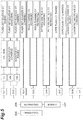
- FIG. 5 is a block diagram illustrating an electric system and a pneumatic-hydraulic system of the machine in Figure 1 .
- the electric system of the flaskless molding machine 100 includes a sequencer 200 (example of control unit), and the electric system is formed by electrically connecting a touch panel 300 ( Figure 1 and Figure 2 , example of input unit), solenoid valves SV1, SV2, SV3, SV5, SV6, SV7, and SV8, and a cut valve CV to the sequencer 200. Further, various kinds of sensors 201 are electrically connected to the sequencer 200.
- Examples of the various kinds of sensors 201 include a sensor that detects a return end (retract end) of the mold pushing cylinder, a pressure switch PS described below, a pressure switch that monitors whether pressure of supplied compressed air is equal to or higher than prescribed pressure, a reed switch or a proximity switch that checks an advance end and a return end of each of the cylinders, and a proximity switch that monitors a thickness of the mold to prevent it from being lower than a prescribed thickness in squeezing.
- the solenoid valves SV1, SV2, and SV3 and the cut valve CV are components of a flask set squeeze cylinder driving mechanism 400 illustrated in Figure 6 , and are described below.
- the solenoid valve SV5 feeds and exhausts compressed air to/from the mold pushing cylinder 31 to advance and retract the piston rod 31a.
- the solenoid valve SV6 feeds and exhausts compressed air to/from the pattern shuttle cylinder 21 to advance and retract the piston rod 21a.
- the solenoid valve SV7 feeds and exhausts compressed air to/from the upper flask cylinder 9 to advance (lower) and retract (raise) the piston rod 9a.
- the solenoid valve SV8 feeds and exhausts compressed air to/from the lower filling frame cylinders 5 to advance (raise) and retract (lower) the piston rods 5a.
- Figure 6 is a pneumatic-hydraulic circuit diagram of the flask set squeeze cylinder driving mechanism of the machine in Figure 1 .
- the flask set squeeze cylinder driving mechanism 400 includes a compressed air source 401, an oil tank 402, and a booster cylinder 403, and is driven by air-on-oil driving derived from a composite circuit including a pneumatic circuit 404 and a hydraulic circuit 405.
- the air-on-oil driving is driving by a pneumatic-hydraulic composite function to transform pneumatic pressure into hydraulic pressure to be used. In the air-on-oil driving, only a compressed air source is used without using a dedicated hydraulic unit using a hydraulic pump.
- the oil tank 402 includes a pneumatic chamber 402a on an upper part, and the pneumatic chamber 402a communicates with one of the compressed air source 401 and the atmosphere (silencer 406) through a valve (first valve) V1 that is controlled in two positions in conjunction with the solenoid valve (first solenoid valve) SV1.
- the solenoid valve SV1 makes a control port of the valve V1 communicate with a silencer 407 to maintain the valve V1 in a non-operation state, and makes the pneumatic chamber 402a of the oil tank 402 communicate with the silencer 406 to maintain atmospheric pressure inside the pneumatic chamber 402a.
- the solenoid valve SV1 makes the control port of the valve V1 communicate with the compressed air source 401 to maintain the valve V1 in an operation state, and makes the pneumatic chamber 402a of the oil tank 402 communicate with the compressed air source 401 to supply the compressed air into the pneumatic chamber 402a.
- the booster cylinder 403 is a booster cylinder using Pascal's principle, and has a pneumatic-hydraulic composite function to transform low pneumatic pressure into high hydraulic pressure to be used. In the air-on-oil driving, a hydraulic pump is unnecessary and only the pneumatic source is used.
- the booster cylinder 403 includes a cylinder portion 403a and a piston portion 403b.
- the cylinder portion 403a includes an upper pneumatic chamber 403c and a lower hydraulic chamber 403d, and an area ratio of a cross-sectional area of the pneumatic chamber 403c and a cross-sectional area of the hydraulic chamber 403d is set to a large value, for example, 10:1.
- the piston portion 403b is disposed in the pneumatic chamber 403c of the cylinder portion 403a, and includes a large-diameter piston portion 403g and a small-diameter piston portion 403h.
- the large-diameter piston portion 403g divides the pneumatic chamber 403c into an upper pneumatic chamber 403e and a lower pneumatic chamber 403f.
- the small-diameter piston portion 403h extends downward from the large-diameter piston portion 403g and has a front end part that is disposed in the hydraulic chamber 403d.
- the booster cylinder 403 generates hydraulic pressure ten times greater than the compressed air pressure.
- the upper pneumatic chamber 403e of the booster cylinder 403 communicates with one of the compressed air source 401 and the atmosphere (silencer 408) through a valve (second valve) V2a that is controlled in two positions in conjunction with the solenoid valve (second solenoid valve) SV2.
- the solenoid valve SV2 makes a control port of the valve V2 communicate with the silencer 407 to maintain the valve V2a in a non-operation state, and makes the upper pneumatic chamber 403e of the booster cylinder 403 communicate with the silencer 408 to maintain atmospheric pressure inside the upper pneumatic chamber 403e.
- the solenoid valve SV2 makes the control port of the valve V2a communicate with the compressed air source 401 to maintain the valve V2a in an operation state, and makes the upper pneumatic chamber 403e communicate with the compressed air source 401 to supply the compressed air into the upper pneumatic chamber 403e.
- a regulator 409 is disposed in a pneumatic piping between the compressed air source 401 and the valve V2a.
- the lower pneumatic chamber 403f of the booster cylinder 403 communicates with one of the compressed air source 401 and the atmosphere (silencer 410) through a valve V2b that is controlled in two positions in conjunction with the solenoid valve SV2.
- the solenoid valve SV2 makes a control port of the valve V2b communicate with the compressed air source 401 to maintain the valve V2b in an operation state, and makes the lower pneumatic chamber 403f of the booster cylinder 403 communicate with the compressed air source 401 to supply the compressed air into the lower pneumatic chamber 403f.
- the solenoid valve SV2 makes the control port of the valve V2b communicate with a silencer 411 to maintain the valve V2a in a non-operation state, and makes the lower pneumatic chamber 403f communicate with the silencer 410 to maintain atmospheric pressure inside the lower pneumatic chamber 403f.
- the flask set squeeze cylinder 2 includes the main body portion (cylinder portion) 2b, a piston 2c disposed inside the main body portion 2b, and the piston rod 2a that extends upward from the piston 2c. As described above, the lower squeeze board 4 is coupled to the front end of the piston rod 2a.
- the main body portion 2b includes an upper pneumatic chamber 2d and a lower hydraulic chamber 2e, and the piston 2c partitions the pneumatic chamber 2d and the hydraulic chamber 2e.
- the pneumatic chamber 2d of the flask set squeeze cylinder 2 communicates with one of the compressed air source 401 and the atmosphere (silencer 407) through the solenoid valve (third solenoid valve) V3.
- the solenoid valve SV3 makes the pneumatic chamber 2d communicate with the silencer 407 to maintain atmospheric pressure inside the pneumatic chamber 2d.
- the solenoid valve SV3 makes the pneumatic chamber 2d communicate with the compressed air source 401 to supply the compressed air into the pneumatic chamber 2d.
- the hydraulic circuit 405 has a configuration in which the oil tank 402 and the hydraulic chamber 2e of the flask set squeeze cylinder 2 fluidly communicate with each other through a hydraulic piping 412, a speed controller SC and the cut valve CV are disposed in a middle of a hydraulic piping portion 412a on the oil tank 402 side, the hydraulic piping portion 412b on the flask set squeeze cylinder 2 side fluidly communicates with the hydraulic chamber 403d of the booster cylinder 403, and the pressure switch PS is disposed in a hydraulic piping portion 412b on the flask set squeeze cylinder 2 side.
- the pressure switch PS monitors that pressure of hydraulic oil 402b inside the hydraulic piping portion 412b becomes predetermined pressure.
- the cut valve CV maintains a shutoff state between the oil tank 402 and the hydraulic chamber 2e of the flask set squeeze cylinder 2 and between the oil tank 402 and the hydraulic chamber 403d of the booster cylinder 403. Further, during energization, the cut valve CV is operated by the compressed air pressure, and maintains a communication state between the oil tank 402 and the hydraulic chamber 2e of the flask set squeeze cylinder 2 and between the oil tank 402 and the hydraulic chamber 403d of the booster cylinder 403.
- Figure 7 is a flowchart illustrating a molding method.
- the flaskless molding method includes a series of steps including a pattern shuttling-in step S1, a flask setting step S2, a sand filling step S3, a squeezing step S4, a mold removing (drawing) step S5, a pattern shuttling-out step S6, a mold mating step S7, a flask stripping-off step S8, and a mold pushing step S9.
- a pattern shuttling-in step S1 a flask setting step S2
- a sand filling step S3 a squeezing step S4
- a mold removing (drawing) step S5 a pattern shuttling-out step S6
- a mold mating step S7 a mold mating step S7
- a flask stripping-off step S8 a mold pushing step S9.
- the solenoid valves SV1 and SV2 are both maintained in the non-energized state, and the solenoid valve SV3 and the cut valve CV are both maintained in the energized state. Since the solenoid valve SV3 is in the energized state, the piston 2c and the piston rod 2a of the flask set squeeze cylinder 2 are located at a lower end (lowered end) and the lower squeeze board 4 is held at the lower end (lowered end). Since the cut valve CV is in the energized state, the cut valve CV maintains the fluid communication state between the oil tank 402 and the hydraulic chamber 2e of the flask set squeeze cylinder 2 and between the oil tank 402 and the hydraulic chamber 403d of the booster cylinder 403.
- step S1 the solenoid valves SV1 and SV2 are both maintained in the non-energized state, and the solenoid valve SV3 and the cut valve CV are both maintained in the energized state, similarly to the beginning of the molding.
- the energization to the solenoid valve SV1 is started and the energization to the solenoid valve SV3 is stopped.
- the hydraulic oil 402b supplied to the hydraulic chamber 2e of the flask set squeeze cylinder 2 raises the piston 2c, the lower squeeze board 4 is raised via the piston rod 2a, and the flask is set.
- the energization to the solenoid valve SV1 and the cut valve CV is stopped, and the energization to the solenoid valve SV2 is started.
- the compressed air supplied into the upper pneumatic chamber 403e of the booster cylinder 403 depresses the large-diameter piston portion 403g.
- the small-diameter piston portion 403h extrudes the hydraulic oil 402b inside the hydraulic chamber 403d along with lowering of the large-diameter piston portion 403g.
- the extruded hydraulic oil 402b is supplied to the hydraulic chamber 2e of the flask set squeeze cylinder 2. Accordingly, the lower squeeze board 4 is raised, and the squeezing step is performed.
- the squeezing step S4 is completed when the pressure switch PS detects that the pressure of the hydraulic oil 402b becomes the predetermined pressure.
- step S5 the energization to the solenoid valve SV2 is stopped, and the energization to the solenoid valve SV3 and the cut valve CV is started.
- the piston portion 403b is raised to an upper end (raised end).
- the energization to the cut valve CV is started, the path between the oil tank 402 and the hydraulic chamber 2e of the flask set squeeze cylinder 2 and the path between the oil tank 402 and the hydraulic chamber 403d of the booster cylinder 403 are returned to the fluid communication state.
- the energization to the solenoid valve SV1 is started and the energization to the solenoid valve SV3 is stopped, similar to the flask setting step S2.
- the hydraulic oil 402b inside the oil tank 402 receives depressing force by the compressed air supplied into the pneumatic chamber 402a, is extruded from the oil tank 402, and is supplied to the hydraulic chamber 2e of the flask set squeeze cylinder 2 through the speed controller SC and the cut valve CV. Accordingly, the piston 2c of the flask set squeeze cylinder 2 is raised.
- the energization to the solenoid valve SV1 is stopped, and the energization to the solenoid valve SV3 is started.
- the pneumatic chamber 2d of the flask set squeeze cylinder 2 communicates with the compressed air source 401, and the compressed air is supplied into the pneumatic chamber 2d.
- the piston 2c of the flask set squeeze cylinder 2 is depressed by the compressed air pressure. Therefore, the hydraulic oil 402b inside the hydraulic chamber 2e is extruded.
- the extruded hydraulic oil 402b is returned into the oil tank 402. As a result, the piston 2c of the flask set squeeze cylinder 2 is lowered.
- a flowchart (B) illustrates operation of the cylinder in each of the steps.
- the piston rod 2a of the flask set squeeze cylinder 2 is located at the retract end and the lower squeeze board 4 is located at the lowered end in the molding unit 100A. Further, the piston rods 5a on the upper side of the respective lower filling frame cylinders 5 are located at the respective retract ends, and the lower filling frame 6 is located at the lowered end. Furthermore, the piston rod 9a of the upper flask cylinder 9 is located at the advance end, and the upper flask 10 is located at the lowered end.
- the piston rod 21a of the pattern shuttle cylinder 21 is located at the retract end, and the master plate 22, the lower flask 23, and the match plate 24 are located at the respective retract ends.
- the piston rod 31a of the mold pushing cylinder 31 is located at the retract end, and the pushing plate 32 is located at the retract end.
- the aeration tank 43 is filled with the molding sand 51 ( Figure 8 ).
- the type of the molding sand 51 is not limited, the molding sand 51 is, for example, green sand using bentonite as a binder.
- the piston rod 21a of the pattern shuttle cylinder 21 is advanced.
- the master plate 22 is accordingly advanced, the two flanged rollers 22b on the left side among the four flanged rollers 22b on the upper side are placed on the paired travelling rails 11, and the four flanged rollers 22c on the lower side are separated from the paired guide rails 25.
- the piston rod 21a is advanced to the advance end, the master plate 22, the lower flask 23, and the match plate 24 are set to respective predetermined positions inside the columns 1c of the molding unit 100A.
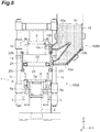
- Figure 8 is a diagram illustrating a state where the pattern shuttling-in step in the molding method has ended.
- the piston rod 2a of the flask set squeeze cylinder 2 is advanced to raise the lower squeeze board 4, and the lower filling frame cylinders 5 are advanced to raise the lower filling frame 6.
- the positioning pins 7 of the lower filling frame 6 are inserted into respective positioning holes (not illustrated) of the lower flask 23 to overlap the lower filling frame 6 with the bottom surface of the lower flask 23.
- a lower mold space that is sealed by the lower squeeze board 4, the lower filling frame 6, the lower flask 23, and the match plate 24 is defined.
- raising and lowering the flask set squeeze cylinder 2 enables the lower squeeze frame 3 to be raised and lowered together with the lower squeeze board 4.
- the lower squeeze frame 3 and the lower squeeze board 4 are integrally raised, the positioning pins 7 are inserted into the bottom surface of the upper flask 10 to overlap the lower flask 23 with the bottom surface of the upper flask 10 with the match plate 24 and the master plate 22 located therebetween.
- an upper mold space that is sealed by the upper squeeze board 8, the upper flask 10, and the match plate 24 is formed.
- the advancing power of the flask set squeeze cylinder 2 at this time is only required for the weight of the object to be raised.
- the relatively low-pressure cylinder can be adopted. Note that, when the upper mold space is formed, the piston rod 2a of the flask set squeeze cylinder 2 has not reached the advance end (raised end).
- Figure 9 is a diagram illustrating a state where the sand filling step in the molding method has ended.
- Figure 9 illustrates a state where the upper mold space and the lower mold space are filled with the molding sand 51; however, the flask setting step S2 corresponds to a state before the molding sand 51 is filled.
- the sand gate 42 ( Figure 2 ) is closed, and the compressed air is supplied into the aeration tank 43.
- the molding sand 51 inside the aeration tank 43 is introduced, by the compressed air pressure, into the lower mold space through the lower sand introduction hole 43a and the molding-sand introduction hole 6c of the lower filling frame 6.
- the molding sand 51 is introduced, by the compressed air pressure, into the upper mold space through the upper sand introduction hole 43a and the molding-sand introduction hole 10c of the upper flask 10.
- the compressed air is exhausted to the outside from an exhaust holes (not illustrated) provided on side walls of the upper flask 10 and the lower flask 23.
- the booster cylinder 403 ( Figure 6 ) is lowered to supply the high-pressure hydraulic oil to the flask set squeeze cylinder 2, and the upper and lower molds with predetermined hardness are formed.
- the pressure switch PS ( Figure 6 ) determines timing when lowering of the booster cylinder 403 is stopped. It is preferable that pressure when the pressure boosting (lowering) of the booster cylinder 403 is stopped be set within a range from 0.1 MPa to 21 MPa. When the pressure exceeds 21 MPa, it is necessary to use the device withstanding pressure of 21 MPa or higher, which increases the cost. In contract, when the pressure is lower than 0.1 MPa, hardness to form a mold is not obtainable.
- the booster cylinder 403 is lowered and the flask set squeeze cylinder 2 is activated at high pressure from the beginning of the squeezing step; however, the flask set squeeze cylinder 2 may be advanced (raised) at low pressure while the booster cylinder 403 is stopped at the beginning of the squeezing step, and the booster cylinder 403 may be then activated. Beginning the squeezing step at low pressure makes it possible to shorten a stroke of the flask set squeeze cylinder 2 for squeezing at high pressure. This allows for further downsizing of the booster cylinder.
- step S5 the piston rod 2a of the flask set squeeze cylinder 2 is retracted to lower the lower squeeze board 4.
- the lower flask 23, the match plate 24, the master plate 22, and the lower filling frame 6 are also lowered along with the lower squeeze board 4.
- the four flanged rollers 22b on the upper side of the master plate 22 are placed on the paired travelling rails 11, the lowering of the master plate 22, the lower flask 23, and the match plate 24 is stopped while the lower squeeze board 4 and the lower filling frame 6 are continuously lowered.
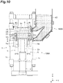
- FIG. 11 is a diagram illustrating a state where the mold removing (drawing) step in the molding method has ended.
- the master plate 22 is coupled to the front end of the piston rod 21a of the pattern shuttle cylinder 21 when the four flanged rollers 22b on the upper side of the master plate 22 are placed on the paired travelling rails 11 in the mold removing (drawing) step S5.
- the piston rod 21a of the pattern shuttle cylinder 21 is retracted to the retract end.
- the four flanged rollers 22b on the lower side of the master plate 22 are placed on the paired guide rails 25 and the two flanged rollers 22b on the left side among the four flanged rollers 22b on the upper side of the master plate 22 are separated from the paired travelling rails 11.
- the master plate 22, the lower flask 23, and the match plate 24 are returned to the respective retract ends (respective original positions).
- a core is settable inside the columns 1c, and the core is set as necessary.
- the core setting is not essential in the present disclosure.
- Figure 12 is a diagram illustrating a state where the pattern shuttling-out step in the molding method has ended.
- the piston rod 2a of the flask set squeeze cylinder 2 is advanced to raise the lower squeeze board 4, thereby bringing the lower mold 55 into close contact with a bottom surface of the upper mold 54.
- the flask set squeeze cylinder 2 is advanced at low pressure while the booster cylinder is stopped as with the flask setting step S2. Further, it is preferable that the flask set squeeze cylinder 2 be moved at low speed immediately before the upper mold 54 and the lower mold 55 are brought into close contact with each other, in order to prevent the molds from collapsing due to impact of the contact.
- Figure 13 is a diagram illustrating a state where the mold mating step in the molding method has ended.
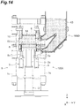
- Figure 14 is a diagram illustrating a state where the upper mold is drawn from the upper flask in the flask stripping-off step in the molding method.
- the piston rod 9a ( Figure 4 ) of the upper flask cylinder 9 ( Figure 4 ) is retracted to raise the upper flask 10. Raising the upper flask 10 causes the upper mold 54 to strip off the upper flask 10.
- the piston rod 9a of the upper flask cylinder 9 is advanced to return the upper flask 10 to the lowered end (original position).
- FIG. 15 is a diagram illustrating a state where the flask stripping-off step in the molding method has ended.
- the flask set squeeze cylinder 2 is retracted at low pressure while the booster cylinder is stopped, as with the mold mating step S7. Further, the flask set squeeze cylinder 2 may be activated at low speed immediately before the lowered end of the flask set squeeze cylinder 2, in order to prevent impact from being applied to the stripped mold.
- the piston rod 31a of the mold pushing cylinder 31 is advanced to advance the pushing plate 32, and the molds (upper mold 54 and lower mold 55) on the lower squeeze board 4 are sent out to a conveyance line. Thereafter, the piston rod 31a of the mold pushing cylinder 31 is retracted and returned to the original position.
- the power of the low-pressure activation to advance or to retract the flask set squeeze cylinder 2 in the flask setting step S2, the mold removing (drawing) step S5, the mold mating step S7, and the flask stripping-off step S8 described above may be set to a range from 0.1 MPa to 0.6 MPa.
- the above-described air-on-oil driving is applied to the flask set squeeze cylinder driving mechanism 400.
- the pressure supplied by the compressed air source 401 is set to about 0.6 MPa. Although it is possible to set the pressure to be higher than 0.6 MPa, it is necessary to improve performance of the compressor. Therefore, the pressure may be set to be equal to or lower than 0.6 MPa in terms of energy saving. Further, when the pressure is lower than 0.1 MPa, it is difficult to drive the flask set squeeze cylinder 2 due to the weight of an object to be driven and frictional resistance of a packing or the like inside the cylinder.
- the piston rod 21a of the pattern shuttle cylinder 21 is advanced and retracted at the pneumatic pressure of 0.1 MPa to 0.6 MPa. As described above, it is sufficient for the pattern shuttle cylinder 21 to advance and retract the master plate 22, the lower flask 23, and the match plate 24. Therefore, the pneumatic pressure of 0.1 MPa to 0.6 MPa is sufficient. As described above, the pressure supplied from the compressed air source in the common foundry is about 0.6 MPa. Therefore, the pneumatic pressure to activate the pattern shuttle cylinder 21 may be set to be equal to or lower than 0.6 MPa in terms of energy saving. If the pneumatic pressure is lower than 0.1 MPa, it is difficult to activate the pattern shuttle cylinder 21 due to the weight of the object to be advanced and retracted, the frictional resistance inside the cylinder, and the like.
- the pneumatic pressure to advance (raise) and retract (lower) the piston rods 5a of the respective lower filling frame cylinders 5 may be 0.1 MPa to 0.6 MPa.
- the lower filling frame cylinders 5 are used to lift up the lower filling frame 6, the lower flask 23, and the match plate 24 and to draw the lower mold from the lower filling frame 6. Therefore, the lower filling frame cylinders 5 can be activated at the pneumatic pressure from 0.1 MPa to 0.6 MPa. Since the pressure supplied from the compressed air source 401 in the common foundry is about 0.6 MPa, the pneumatic pressure to activate the lower filling frame cylinders 5 may be set to be equal to or lower than 0.6 MPa in terms of energy saving. If the pneumatic pressure is lower than 0.1 MPa, it is difficult to activate the lower filling frame cylinders 5 due to the weight of the object to be raised and the frictional resistance inside the cylinder.
- the above-described flaskless molding machine 100 can form the upper mold and the lower mold with only one type of a height.
- a mold height changing unit 500 applicable to the above-described flaskless molding machine 100 will be described.
- the mold height changing unit 500 may include a spacer member to change the mold height.
- Figure 16 is a diagram illustrating an example of an attachment position of the spacer member according to the embodiment. As illustrated in Figure 16 , a spacer member 600 is attached on a bottom surface 8c (example of principle surface facing match plate 24) of the upper squeeze board 8. The spacer member 600 is fixed to the bottom surface 8c of the upper squeeze board 8 by, for example, screws. Note that, in a case where screw holes (liner attachment screw holes) for attachment of a liner serving as an abrasion countermeasure are provided on the bottom surface 8c of the upper squeeze board 8, the spacer member 600 may be fixed to the upper squeeze board 8 with use of such screw holes.
- a material of the spacer member 600 is not particularly limited, for example, a resin is used.
- a weight of the spacer member 600 is reduced as compared with a case where the spacer member 600 is made of a metal. This facilitates attachment of the spacer member 600.
- a thickness of the spacer member 600 is not particularly limited, the spacer member 600 has a thickness of, for example, about 15 mm to about 75 mm. Providing the spacer member 600 makes it possible to reduce the height of the molding space for the upper mold by the thickness of the spacer member 600. As a result, it is possible to reduce the thickness of the upper mold.
- the mold height changing unit 500 may include a stopper to change the height of the lower mold.
- Figure 17 and Figure 18 are diagrams each illustrating an example of an attachment position of the stopper according to the embodiment. As illustrated in Figure 17 and Figure 18 , at least one stopper 601 that limits stroke lengths of the lower filling frame cylinders 5 to predetermined lengths is attached to the lower filling frame 6. As an example, two stoppers 601 are provided at each of two opposing end parts of the lower filling frame 6.
- each of the stoppers 601 includes a rod member 602 and a contact member 603.
- Each of the rod members 602 includes a first end part 602a and a second end part 602b.
- the first end parts 602a are detachably attached to the lower filling frame 6.
- the first end parts 602a are fixed to the lower filling frame 6 by screws 604 to 606.
- Through holes 3e are provided at the lower end part 3b of the lower squeeze frame 3 to which the lower filling frame cylinders 5 are fixed.
- the rod members 602 extend downward from the lower filling frame 6 and are inserted into the respective through holes 3e provided on the lower squeeze frame 3 that supports the lower filling frame cylinders 5.
- a length (projection length L1) from the lower squeeze frame 3 to the contact members 603 of the rod members 602 is shorter than the stroke lengths of the lower filling frame cylinders 5. More specifically, when the lower filling frame 6 is located at a position closest to the lower squeeze frame 3, the length (projection length L1) from the bottom surface (contact surface) of the lower squeeze frame 3 to the top surfaces (contact surfaces) of the contact members 603 of the rod members 602 is shorter than the stroke lengths of the lower filling frame cylinders 5.
- the stroke length is a sliding distance in one stroke of the cylinder, and is a distance from a top dead center to a bottom dead center.
- the contact members 603 are attached to the second end parts 602b of the respective rod members 602.
- the contact members 603 are detachable from the rod members 602.
- the contact members 603 are nuts, and are attached to the second end parts 602b of the respective rod members 602 by being screwed with male screws provided at the second end parts 602b.
- the contact members 603 each have a size and a shape that cannot pass through the through holes 3e.
- the rod members 602 and the contact members 603 are moved together with the lower filling frame 6 by the lower filling frame cylinders 5. Therefore, in the case where the lower filling frame 6 is moved by a length equal to or larger than the projection length L1 in a direction separating from the lower end part 3b of the lower squeeze frame 3, the contact members 603 abut on the lower squeeze frame 3. This restricts the movement of the lower filling frame cylinders 5 in the expanding direction, and limits the relative distance between the lower filling frame 6 and the lower squeeze frame 3. As a result, the height of the molding space is changed.
- Figure 19 is a diagram illustrating the height of the molding space changed by the stoppers according to the embodiment.
- a diagram illustrated on left side of an alternate long and short dash line illustrates expansion end positions of the lower filling frame cylinders 5 in the machine provided with no stopper 601.
- a diagram illustrated on right side of the alternate long and short dash line illustrates the expansion end positions of the lower filling frame cylinders 5 in the machine provided with the stoppers 601.
- the lower filling frame 6 is raised up to the expansion end positions of the lower filling frame cylinders 5.
- the molding operation is executed while the lower filling frame 6 is located at the expansion end positions of the lower filling frame cylinders 5.
- a height from an upper end of the lower filling frame 6 coupled to the lower flask 23 to the lower squeeze board 4 is denoted by H1.
- the raising of the lower filling frame 6 is limited by the stoppers 601 before the lower filling frame 6 is raised to the expansion end positions of the lower filling frame cylinders 5. More specifically, the raising of the lower filling frame 6 is limited to the projection length L1. A height from the upper end of the lower filling frame 6 coupled to the lower flask 23 to the lower squeeze board 4 is denoted by H2. As a result of provision of the stoppers 601, the height of the molding space for the lower mold is reduced by a height H3 that is obtained by subtracting the height H2 from the height H1. As a result, it is possible to reduce the thickness of the lower mold.
- Such stoppers 601 are more effective to the flaskless molding machine in which the positions of the lower filling frame cylinders 5 are not controlled.
- the flaskless molding machine in which the positions of the lower filling frame cylinders 5 are not controlled has various advantages such as a simple structure, less occurrence of machine stoppage caused by minor abnormality of the cylinders, and high positional accuracy.
- the flaskless molding machine in which the positions of the lower filling frame cylinders 5 are not controlled has disadvantage that the thickness of the mold is not changeable. Providing the stoppers 601, however, can eliminate only the disadvantage.
- the mold height changing unit 500 may include the touch panel 300 that is connected to the sequencer 200 and allows for selection of one of the first mode and the second mode. Note that, in the second mode, the above-described spacer member 600 that is attached to the bottom surface 8c of the upper squeeze board 8 may be used.
- FIG. 20 is a diagram illustrating another example of a stopper according to the embodiment.
- each of the lower filling frame cylinders 5 includes a stopper 611. It is sufficient to provide the stopper 611 on at least one of the lower filling frame cylinders 5 provided in the flaskless molding machine 100.
- each of the four lower filling frame cylinders 5 includes the stopper 611.
- the stoppers 611 limit the stroke lengths of the lower filling frame cylinders 5 to predetermined lengths, as with the stoppers 601. In other words, the flaskless molding machine 100 can adopt the stoppers 611 in place of the stoppers 601.
- each of the stoppers 611 includes a rod member 612 and a contact member 613.
- Each of the rod members 612 includes a first end part 612a and a second end part 612b.
- the first end parts 612a of the rod members 612 are provided at the lower ends of the piston rods 5a of the respective lower filling frame cylinders 5 such that the rod members 612 are integrally operated with the piston rods 5a of the respective lower filling frame cylinders 5.
- the second end parts 612b of the rod members 612 are located below the respective lower filling frame cylinders 5.
- the rod members 612 enter the respective lower filling frame cylinders 5 along with rise of the piston rods 5a.
- the contact members 613 are attached to the second end parts 612b of the respective rod members 612.
- a length (projection length L2) from the lower ends of the lower filling frame cylinders 5 to the contact members 613 of the rod members 612 is shorter than the stroke lengths of the lower filling frame cylinders 5. More specifically, when the lower filling frame 6 is located at a position closest to the lower squeeze frame 3, the length (projection length L2) from the lower ends (contact surfaces) of the lower filling frame cylinders 5 to the top surfaces (contact surfaces) of the contact members 613 of the rod members 612 is shorter than the stroke lengths of the lower filling frame cylinders 5.
- the contact members 613 are detachable from the respective rod members 612.
- the contact members 613 are nuts, and are attached to the rod members 612 by being screwed with male screws provided at the second end parts 612b of the rod members 612.
- the contact members 613 each have a cross-sectional surface larger than a cross-sectional surface of each of the rod members 612.
- the rod members 612 and the contact members 613 are moved together with the piston rods 5a of the lower filling frame cylinders 5. Therefore, in the case where the piston rods 5a have been expanded to be equal to or larger than the projection length L2, the contact members 613 abut on the lower ends of the lower filling frame cylinders 5. This restricts the movement of the lower filling frame cylinders 5 in the expanding direction, and limits the relative distance between the lower filling frame 6 and the lower squeeze frame 3. As a result, the height of the molding space is changed.
- Liner members 614 to prevent abrasion may be provided at the lower ends of the lower filling frame cylinders 5.
- Each of the rod members 612 and the corresponding piston rod 5a may be made up of a single member.
- the lower filling frame cylinders 5 may be so-called double-rod cylinders.
- the positions of the expansion ends (top dead centers) of the lower filling frame cylinders 5 are changed.
- the height position in the mold mating and the position at which the thickness of the mold is monitored in the squeezing are also changed.
- the mold height changing unit 500 is provided, as an example of the sensors 201, position detection sensors that each detect the expansion ends (example of predetermined length) of the lower filling frame cylinders 5 after the mold height is changed, the position at which the mold thickness is monitored after the mold height is changed, and the height position in the mold mating after the mold height is changed may be further provided.
- the position detection sensors a proximal sensor or a reed switch that is provided at each stop position and detects the stop position, or an encoder that can constantly detect the position over a predetermined range (movable range) is used.
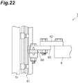
- a position detection sensor 70 includes a magnet 60 and a magnetic field detection section 61.
- the magnet 60 is attached to members 62 and 63 that are moved together with the lower filling frame 6.
- the magnet 60 may be directly attached to the lower filling frame 6.
- the magnet 60 is an annular member having a partial notch.
- the magnetic field detection section 61 consists of a longitudinal member that is attached to the columns 1c as the fixing frames and extends in the top-bottom direction, and detects a magnetic field occurred between the magnet 60 and the magnetic field detection section 61.
- the magnetic field detection section 61 is provided along a moving direction of the lower filling frame 6.
- the magnet 60 is disposed such that the magnetic field detection section 61 is located inside the magnet 60. Since the magnet 60 is moved together with the lower filling frame 6, the position detection sensor 70 can detect the height position (absolute position) of the lower filling frame 6 through detection of the magnetic field position.
- Figure 23 is a diagram illustrating the state where the sand filling step has ended in the case where the height of the molding space is changed.
- the position detection sensor 70 is provided to detect the changed height position of the lower filling frame 6.
- the position detection sensor 70 that monitors the thickness of the mold to prevent it from being lower than the predetermined thickness in the squeezing may be separately added.
- the sensors 201 are connected to the sequencer 200.
- the sequencer 200 may display a detection result of the position detection sensor 70 on the touch panel 300. For example, during monitoring to prevent the thickness of the mold from being lower than the predetermined thickness in the squeezing, an alarm and the like are output based on the detection result of the position detection sensor 70.
- the sequencer 200 may display a monitoring result based on a monitoring mode. For example, in a first monitoring mode, the sequencer 200 monitors only the mold height of the upper flask 10 and displays a result of the monitoring. In a second monitoring mode, the sequencer 200 monitors only the mold height of the lower flask 23 and displays a result of the monitoring.
- the sequencer 200 monitors the mold height of each of the upper flask 10 and the lower flask 23 and displays a result of the monitoring.
- the touch panel 300 may display a screen for selection of the monitoring mode, and causes a worker to select the monitoring mode. Note that, as described above, in the case where the mold height changing unit 500 is attached, the monitoring position is changed. Therefore, the flaskless molding machine 100 may include the touch panel 300 on which the worker can select whether the mold height changing unit 500 has been attached. When the worker selects attachment of the mold height changing unit 500, the sequencer 200 may display a monitoring result on the touch panel 300, based on the position detection sensor that detects the changed height position.
- the sequencer 200 may change the mold height based on the position detection sensor.
- the above-described sensors 201 include, for example, a first position detection sensor detecting that the lower filling frame cylinders 5 have been expanded to the expansion ends (example of first length), and a second position detection sensor detecting that the lower filling frame cylinders 5 have been expanded to a length lower than the expansion ends (example of second length).
- the sequencer 200 is configured to switch a mode between a first operation mode in which the lower filling frame cylinders 5 are operated to be expanded up to the expansion ends based on the detection result of the first position detection sensor, and a second operation mode in which the lower filling frame cylinders 5 are operated to be expanded up to the length lower than the expansion ends based on the detection result of the second position detection sensor.
- the sequencer 200 stops the lower filling frame cylinders 5 when the position detection sensor detects that the lower filling frame cylinders 5 have been expanded up to the length lower than the expansion ends. This makes it possible to change the mold height.
- the sequencer 200 may further include one or a plurality of other operation modes as necessary.
- a third position detection sensor may be further provided to execute a third operation mode.
- the sequencer 200 operates the lower filling frame cylinders 5 to be expanded up to a position detected by the third position detection sensor.
- the encoder in Figure 21 and Figure 22 constantly detects the position. Therefore, in the case where the encoder in Figure 21 and Figure 22 is used, it is possible to easily add an optional number of operation modes without newly providing a position detection sensor.
- the mold height can be changed.
- the mold height can be changed in the following order. First, a second filling frame cylinder that has a stroke length different from a stroke length of a first filling frame cylinder is prepared. Next, the first filling frame cylinder is replaced with the second filling frame cylinder.
- the mold height can be easily changed in the above-described manner.
- Figure 24 is a diagram illustrating a method of changing the height of the molding space.
- An element (A) of Figure 24 illustrates positional relationship between the upper squeeze board 8 and the upper flask 10 before the height of the upper molding space is changed.
- the mold height changing method includes, for example, a step of attaching the spacer member 600 having the thickness d1 to the bottom surface 8c (principle surface facing match plate 24) of the upper squeeze board 8.
- the height of the upper molding space is reduced by the thickness d1 of the spacer member 600.
- an upper squeeze board 8A having a thickness larger by the thickness d1 than the thickness of the upper squeeze board 8 (third squeeze board having thickness different from thickness of first squeeze board) may be prepared, and the upper squeeze board 8 may be replaced with the upper squeeze board 8A.
- the mold height changing method may include a step of attaching a spacer member 600A having the thickness d1 to a top surface 8d on side opposite to the bottom surface 8c of the upper squeeze board 8.
- the height of the upper molding space is reduced by the thickness d1 of the spacer member 600A.
- the mold height changing method includes any one of the above-described steps.
- the lower squeeze board 4 and the lower filling frame cylinders 5 are integrally operated. Further, the stroke lengths of the lower filling frame cylinders 5 are limited to the predetermined length by the stoppers 601. When the stroke lengths of the lower filling frame cylinders 5 are limited by the stoppers 601, the raising distance of the lower filling frame 6 with respect to the lower squeeze board 4 (movable distance of lower filling frame 6 toward lower flask 23) is reduced.
- the mold height changing unit 500 can change the mold height with use of the stoppers 601.
- the mold height can be changed at low cost only by attaching the spacer member 600 or the stoppers 601.
- the above-described embodiment illustrates an example of the flaskless molding machine according to the present disclosure.
- the flaskless molding machine according to the present disclosure is not limited to the flaskless molding machine 100 according to the embodiment, and the flaskless molding machine 100 according to the embodiment may be deformed or applied to the other apparatus without departing from the scope described in appended claims.
- the pneumatic cylinder is used as the pattern shuttle cylinder 21 in the embodiment, an electric cylinder may be used in place of the pneumatic cylinder. In the case of using the electric cylinder, the pneumatic piping for the pattern shuttle cylinder 21 becomes unnecessary, which results in a simple configuration.
- the squeeze force is applied from the lower side toward the upper side in the embodiment, the squeeze force may be applied from the upper side toward the lower side or in the horizontal direction.
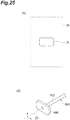
- Figure 25 is a diagram illustrating another example of the stopper according to the embodiment. As illustrated in an element (A) of Figure 25 , a through hole 3f having an asymmetric opening is provided at the lower end part 3b of the lower squeeze frame 3. Further, as illustrated in an element (B) of Figure 25 , a contact member 608 having an asymmetric shape corresponding to the shape of the through hole 3f is attached to each of the second end parts 602b of the rod members 602. The contact member 608 is attached to be rotatable around an axis Z1 of each of the rod members 602. Such a configuration makes it possible to change the mold height only by changing a direction of the contact member 608.
- Flask set squeeze cylinder (squeeze cylinder), 4... Lower squeeze board (second squeeze board), 5... Lower filling frame cylinder (filling frame cylinder), 6... Lower filling frame (filling frame), 8... Upper squeeze board (first squeeze board), 8A... Upper squeeze board (third squeeze board), 10... Upper flask, 21...Pattern shuttle cylinder, 23...Lower flask, 24...Match plate, 51...Molding sand, 54...Upper mold, 55...Lower mold, 100...Flaskless molding machine, 500...Mold height changing unit, 600...Spacer member, 601, 611...Stopper.
Landscapes
- Engineering & Computer Science (AREA)
- Mechanical Engineering (AREA)
- Casting Devices For Molds (AREA)
Applications Claiming Priority (2)
| Application Number | Priority Date | Filing Date | Title |
|---|---|---|---|
| JP2017139042 | 2017-07-18 | ||
| PCT/JP2018/015575 WO2019017024A1 (ja) | 2017-07-18 | 2018-04-13 | 鋳型高さ変更ユニット、抜枠造型機、及び、鋳型高さ変更方法 |
Publications (2)
| Publication Number | Publication Date |
|---|---|
| EP3656484A1 true EP3656484A1 (de) | 2020-05-27 |
| EP3656484A4 EP3656484A4 (de) | 2020-12-16 |
Family
ID=65016084
Family Applications (1)
| Application Number | Title | Priority Date | Filing Date |
|---|---|---|---|
| EP18834651.4A Withdrawn EP3656484A4 (de) | 2017-07-18 | 2018-04-13 | Vorrichtung zum verändern der höhe einer gussform, kastenlose formmaschine und verfahren zum verändern der höhe einer gussform |
Country Status (8)
| Country | Link |
|---|---|
| US (1) | US20200222973A1 (de) |
| EP (1) | EP3656484A4 (de) |
| JP (1) | JP6856123B2 (de) |
| KR (1) | KR20200031640A (de) |
| CN (1) | CN110891709A (de) |
| RU (1) | RU2020106895A (de) |
| TW (1) | TW201908032A (de) |
| WO (1) | WO2019017024A1 (de) |
Families Citing this family (3)
| Publication number | Priority date | Publication date | Assignee | Title |
|---|---|---|---|---|
| JP7559658B2 (ja) * | 2021-04-08 | 2024-10-02 | 新東工業株式会社 | 造型ユニット、造型機及び造型方法 |
| CN113441687B (zh) * | 2021-06-11 | 2022-06-17 | 河北中和铸造有限公司 | 一种铸造用自动造型机 |
| CN114130965B (zh) * | 2022-01-05 | 2025-01-28 | 保定维尔铸造机械股份有限公司 | 一种垂直分型无箱射压造型机的电液混动式动力系统 |
Family Cites Families (11)
| Publication number | Priority date | Publication date | Assignee | Title |
|---|---|---|---|---|
| JPS5924552A (ja) * | 1982-07-30 | 1984-02-08 | Sintokogio Ltd | 無枠式上・下鋳型同時造型機 |
| JPH0688101B2 (ja) * | 1993-03-11 | 1994-11-09 | 金森新東株式会社 | 鋳型造型方法及び装置 |
| JP3264418B2 (ja) * | 1995-11-10 | 2002-03-11 | 新東工業株式会社 | 高さが異なる2種の鋳枠を用いる鋳型造型装置 |
| JP2983208B1 (ja) * | 1998-09-21 | 1999-11-29 | メタルエンジニアリング株式会社 | 鋳型造型装置 |
| CN100515602C (zh) * | 2001-08-06 | 2009-07-22 | 新东工业株式会社 | 监控制模机的系统 |
| JP3729197B2 (ja) * | 2001-08-06 | 2005-12-21 | 新東工業株式会社 | 鋳型造型機をモニタする方法及びシステム |
| JP5168743B2 (ja) * | 2009-11-05 | 2013-03-27 | 新東工業株式会社 | 同時鋳型造型方法及び抜枠鋳型造型装置 |
| JP5126695B2 (ja) * | 2009-10-28 | 2013-01-23 | 新東工業株式会社 | 抜枠鋳型造型装置 |
| KR101133904B1 (ko) * | 2010-01-15 | 2012-04-09 | 신토고교 가부시키가이샤 | 무틀식 주형 조형기 |
| WO2011142049A1 (ja) * | 2010-05-13 | 2011-11-17 | 新東工業株式会社 | 鋳型造型装置及び鋳型造型方法 |
| CN105234354B (zh) * | 2015-11-16 | 2017-03-22 | 广州市铸王机械设备有限公司 | 一种自动砂块成型设备 |
-
2018
- 2018-04-13 EP EP18834651.4A patent/EP3656484A4/de not_active Withdrawn
- 2018-04-13 KR KR1020207003882A patent/KR20200031640A/ko not_active Withdrawn
- 2018-04-13 RU RU2020106895A patent/RU2020106895A/ru unknown
- 2018-04-13 CN CN201880046911.4A patent/CN110891709A/zh active Pending
- 2018-04-13 JP JP2019530879A patent/JP6856123B2/ja active Active
- 2018-04-13 US US16/630,958 patent/US20200222973A1/en not_active Abandoned
- 2018-04-13 WO PCT/JP2018/015575 patent/WO2019017024A1/ja not_active Ceased
- 2018-05-03 TW TW107115005A patent/TW201908032A/zh unknown
Also Published As
| Publication number | Publication date |
|---|---|
| KR20200031640A (ko) | 2020-03-24 |
| BR112020000598A2 (pt) | 2020-07-14 |
| RU2020106895A (ru) | 2021-08-18 |
| CN110891709A (zh) | 2020-03-17 |
| US20200222973A1 (en) | 2020-07-16 |
| TW201908032A (zh) | 2019-03-01 |
| WO2019017024A1 (ja) | 2019-01-24 |
| EP3656484A4 (de) | 2020-12-16 |
| JPWO2019017024A1 (ja) | 2020-05-28 |
| JP6856123B2 (ja) | 2021-04-07 |
Similar Documents
| Publication | Publication Date | Title |
|---|---|---|
| EP2511025B1 (de) | Formmachine und Formverfahren | |
| EP3656484A1 (de) | Vorrichtung zum verändern der höhe einer gussform, kastenlose formmaschine und verfahren zum verändern der höhe einer gussform | |
| US8316918B2 (en) | Flaskless molding machine | |
| JP2018535097A (ja) | アクチュエータ装置 | |
| CN103419323B (zh) | 快速换模装置及注塑机及注塑机的快速换模方法 | |
| US20140182805A1 (en) | Flaskless molding equipment for molding a mold | |
| CN204247917U (zh) | 一种水平射砂水平分型粘土砂全自动造型机 | |
| CN103170519B (zh) | 一种半固态金属成形用多向挤压液压机 | |
| KR101046498B1 (ko) | 조형기 | |
| CN201744626U (zh) | 砂型造型设备中的驱动机构以及脱箱铸型造型装置 | |
| CN202715826U (zh) | 一种磁场液压机抽真空成型装置 | |
| CN104669661A (zh) | 一种四柱液压机的压制方法 | |
| CN104552838A (zh) | 一种自动开合模机 | |
| CN203972673U (zh) | 线材一次成型自动退料装置 | |
| BR112020000598B1 (pt) | Máquina de moldagem sem caixa de fundição | |
| JP5027879B2 (ja) | マッチプレート造型機 | |
| KR20140123197A (ko) | 하이브리드 다이캐스팅 금형장치 | |
| CN102962279A (zh) | 一种反向挤压机 | |
| CN202656383U (zh) | 快速换模装置及注塑机 | |
| CN202367164U (zh) | 造型机合箱与开箱机构液压系统 | |
| US20030051852A1 (en) | Die-casting systems and machines and methods for withdrawing cores in die-casting systems and machines | |
| CN104139454A (zh) | 液压压砖机的脱模装置及其脱模方法 | |
| CN104084500A (zh) | 线材一次成型自动退料装置 | |
| CN103008572A (zh) | 气悬浮拖板 |
Legal Events
| Date | Code | Title | Description |
|---|---|---|---|
| STAA | Information on the status of an ep patent application or granted ep patent |
Free format text: STATUS: THE INTERNATIONAL PUBLICATION HAS BEEN MADE |
|
| PUAI | Public reference made under article 153(3) epc to a published international application that has entered the european phase |
Free format text: ORIGINAL CODE: 0009012 |
|
| STAA | Information on the status of an ep patent application or granted ep patent |
Free format text: STATUS: REQUEST FOR EXAMINATION WAS MADE |
|
| 17P | Request for examination filed |
Effective date: 20200102 |
|
| AK | Designated contracting states |
Kind code of ref document: A1 Designated state(s): AL AT BE BG CH CY CZ DE DK EE ES FI FR GB GR HR HU IE IS IT LI LT LU LV MC MK MT NL NO PL PT RO RS SE SI SK SM TR |
|
| AX | Request for extension of the european patent |
Extension state: BA ME |
|
| DAV | Request for validation of the european patent (deleted) | ||
| DAX | Request for extension of the european patent (deleted) | ||
| A4 | Supplementary search report drawn up and despatched |
Effective date: 20201112 |
|
| RIC1 | Information provided on ipc code assigned before grant |
Ipc: B22C 15/02 20060101ALI20201106BHEP Ipc: B22C 11/00 20060101ALI20201106BHEP Ipc: B22C 11/02 20060101ALI20201106BHEP Ipc: B22C 15/28 20060101AFI20201106BHEP Ipc: B22C 19/04 20060101ALI20201106BHEP Ipc: B22C 11/10 20060101ALI20201106BHEP Ipc: B22C 15/08 20060101ALI20201106BHEP |
|
| STAA | Information on the status of an ep patent application or granted ep patent |
Free format text: STATUS: THE APPLICATION IS DEEMED TO BE WITHDRAWN |
|
| 18D | Application deemed to be withdrawn |
Effective date: 20210612 |