EP3656541A1 - Capsule de poudre en cours de procédé imprimée en 3d pour la caractérisation de poudre de matériau d'impression - Google Patents
Capsule de poudre en cours de procédé imprimée en 3d pour la caractérisation de poudre de matériau d'impression Download PDFInfo
- Publication number
- EP3656541A1 EP3656541A1 EP19207662.8A EP19207662A EP3656541A1 EP 3656541 A1 EP3656541 A1 EP 3656541A1 EP 19207662 A EP19207662 A EP 19207662A EP 3656541 A1 EP3656541 A1 EP 3656541A1
- Authority
- EP
- European Patent Office
- Prior art keywords
- powder
- sintered
- capsule
- sintering
- layer
- Prior art date
- Legal status (The legal status is an assumption and is not a legal conclusion. Google has not performed a legal analysis and makes no representation as to the accuracy of the status listed.)
- Withdrawn
Links
Images


Classifications
-
- B—PERFORMING OPERATIONS; TRANSPORTING
- B29—WORKING OF PLASTICS; WORKING OF SUBSTANCES IN A PLASTIC STATE IN GENERAL
- B29C—SHAPING OR JOINING OF PLASTICS; SHAPING OF MATERIAL IN A PLASTIC STATE, NOT OTHERWISE PROVIDED FOR; AFTER-TREATMENT OF THE SHAPED PRODUCTS, e.g. REPAIRING
- B29C64/00—Additive manufacturing, i.e. manufacturing of three-dimensional [3D] objects by additive deposition, additive agglomeration or additive layering, e.g. by 3D printing, stereolithography or selective laser sintering
- B29C64/10—Processes of additive manufacturing
- B29C64/141—Processes of additive manufacturing using only solid materials
- B29C64/153—Processes of additive manufacturing using only solid materials using layers of powder being selectively joined, e.g. by selective laser sintering or melting
-
- B—PERFORMING OPERATIONS; TRANSPORTING
- B22—CASTING; POWDER METALLURGY
- B22F—WORKING METALLIC POWDER; MANUFACTURE OF ARTICLES FROM METALLIC POWDER; MAKING METALLIC POWDER; APPARATUS OR DEVICES SPECIALLY ADAPTED FOR METALLIC POWDER
- B22F10/00—Additive manufacturing of workpieces or articles from metallic powder
- B22F10/20—Direct sintering or melting
- B22F10/28—Powder bed fusion, e.g. selective laser melting [SLM] or electron beam melting [EBM]
-
- B—PERFORMING OPERATIONS; TRANSPORTING
- B22—CASTING; POWDER METALLURGY
- B22F—WORKING METALLIC POWDER; MANUFACTURE OF ARTICLES FROM METALLIC POWDER; MAKING METALLIC POWDER; APPARATUS OR DEVICES SPECIALLY ADAPTED FOR METALLIC POWDER
- B22F5/00—Manufacture of workpieces or articles from metallic powder characterised by the special shape of the product
- B22F5/10—Manufacture of workpieces or articles from metallic powder characterised by the special shape of the product of articles with cavities or holes, not otherwise provided for in the preceding subgroups
-
- B—PERFORMING OPERATIONS; TRANSPORTING
- B29—WORKING OF PLASTICS; WORKING OF SUBSTANCES IN A PLASTIC STATE IN GENERAL
- B29C—SHAPING OR JOINING OF PLASTICS; SHAPING OF MATERIAL IN A PLASTIC STATE, NOT OTHERWISE PROVIDED FOR; AFTER-TREATMENT OF THE SHAPED PRODUCTS, e.g. REPAIRING
- B29C64/00—Additive manufacturing, i.e. manufacturing of three-dimensional [3D] objects by additive deposition, additive agglomeration or additive layering, e.g. by 3D printing, stereolithography or selective laser sintering
- B29C64/20—Apparatus for additive manufacturing; Details thereof or accessories therefor
- B29C64/255—Enclosures for the building material, e.g. powder containers
-
- B—PERFORMING OPERATIONS; TRANSPORTING
- B29—WORKING OF PLASTICS; WORKING OF SUBSTANCES IN A PLASTIC STATE IN GENERAL
- B29C—SHAPING OR JOINING OF PLASTICS; SHAPING OF MATERIAL IN A PLASTIC STATE, NOT OTHERWISE PROVIDED FOR; AFTER-TREATMENT OF THE SHAPED PRODUCTS, e.g. REPAIRING
- B29C64/00—Additive manufacturing, i.e. manufacturing of three-dimensional [3D] objects by additive deposition, additive agglomeration or additive layering, e.g. by 3D printing, stereolithography or selective laser sintering
- B29C64/30—Auxiliary operations or equipment
- B29C64/386—Data acquisition or data processing for additive manufacturing
-
- B—PERFORMING OPERATIONS; TRANSPORTING
- B33—ADDITIVE MANUFACTURING TECHNOLOGY
- B33Y—ADDITIVE MANUFACTURING, i.e. MANUFACTURING OF THREE-DIMENSIONAL [3D] OBJECTS BY ADDITIVE DEPOSITION, ADDITIVE AGGLOMERATION OR ADDITIVE LAYERING, e.g. BY 3D PRINTING, STEREOLITHOGRAPHY OR SELECTIVE LASER SINTERING
- B33Y10/00—Processes of additive manufacturing
-
- B—PERFORMING OPERATIONS; TRANSPORTING
- B33—ADDITIVE MANUFACTURING TECHNOLOGY
- B33Y—ADDITIVE MANUFACTURING, i.e. MANUFACTURING OF THREE-DIMENSIONAL [3D] OBJECTS BY ADDITIVE DEPOSITION, ADDITIVE AGGLOMERATION OR ADDITIVE LAYERING, e.g. BY 3D PRINTING, STEREOLITHOGRAPHY OR SELECTIVE LASER SINTERING
- B33Y30/00—Apparatus for additive manufacturing; Details thereof or accessories therefor
-
- B—PERFORMING OPERATIONS; TRANSPORTING
- B33—ADDITIVE MANUFACTURING TECHNOLOGY
- B33Y—ADDITIVE MANUFACTURING, i.e. MANUFACTURING OF THREE-DIMENSIONAL [3D] OBJECTS BY ADDITIVE DEPOSITION, ADDITIVE AGGLOMERATION OR ADDITIVE LAYERING, e.g. BY 3D PRINTING, STEREOLITHOGRAPHY OR SELECTIVE LASER SINTERING
- B33Y80/00—Products made by additive manufacturing
-
- G—PHYSICS
- G01—MEASURING; TESTING
- G01N—INVESTIGATING OR ANALYSING MATERIALS BY DETERMINING THEIR CHEMICAL OR PHYSICAL PROPERTIES
- G01N1/00—Sampling; Preparing specimens for investigation
- G01N1/28—Preparing specimens for investigation including physical details of (bio-)chemical methods covered elsewhere, e.g. G01N33/50, C12Q
-
- Y—GENERAL TAGGING OF NEW TECHNOLOGICAL DEVELOPMENTS; GENERAL TAGGING OF CROSS-SECTIONAL TECHNOLOGIES SPANNING OVER SEVERAL SECTIONS OF THE IPC; TECHNICAL SUBJECTS COVERED BY FORMER USPC CROSS-REFERENCE ART COLLECTIONS [XRACs] AND DIGESTS
- Y02—TECHNOLOGIES OR APPLICATIONS FOR MITIGATION OR ADAPTATION AGAINST CLIMATE CHANGE
- Y02P—CLIMATE CHANGE MITIGATION TECHNOLOGIES IN THE PRODUCTION OR PROCESSING OF GOODS
- Y02P10/00—Technologies related to metal processing
- Y02P10/25—Process efficiency
-
- Y—GENERAL TAGGING OF NEW TECHNOLOGICAL DEVELOPMENTS; GENERAL TAGGING OF CROSS-SECTIONAL TECHNOLOGIES SPANNING OVER SEVERAL SECTIONS OF THE IPC; TECHNICAL SUBJECTS COVERED BY FORMER USPC CROSS-REFERENCE ART COLLECTIONS [XRACs] AND DIGESTS
- Y10—TECHNICAL SUBJECTS COVERED BY FORMER USPC
- Y10T—TECHNICAL SUBJECTS COVERED BY FORMER US CLASSIFICATION
- Y10T428/00—Stock material or miscellaneous articles
- Y10T428/13—Hollow or container type article [e.g., tube, vase, etc.]
-
- Y—GENERAL TAGGING OF NEW TECHNOLOGICAL DEVELOPMENTS; GENERAL TAGGING OF CROSS-SECTIONAL TECHNOLOGIES SPANNING OVER SEVERAL SECTIONS OF THE IPC; TECHNICAL SUBJECTS COVERED BY FORMER USPC CROSS-REFERENCE ART COLLECTIONS [XRACs] AND DIGESTS
- Y10—TECHNICAL SUBJECTS COVERED BY FORMER USPC
- Y10T—TECHNICAL SUBJECTS COVERED BY FORMER US CLASSIFICATION
- Y10T428/00—Stock material or miscellaneous articles
- Y10T428/13—Hollow or container type article [e.g., tube, vase, etc.]
- Y10T428/1352—Polymer or resin containing [i.e., natural or synthetic]
Definitions
- Three-dimensional (3D) printing is an additive printing process used to make three-dimensional solid objects from a digital model.
- 3D printing may be used in various processes including but not limited to rapid product prototyping, product manufacturing, mold generation, and mold master generation.
- 3D printing techniques are considered additive processes because they involve the application of successive layers of material. This is unlike traditional machining processes, which often rely upon the removal of material to create the final object.
- Various materials may be used in 3D printing. For example, materials such as polymide, alumide, titanium, or thermoplastic polyurethane may be used in 3D printing.
- Some 3D printing techniques utilize powder as the basic material, then transform the powder into a desired shape or structures to form a product.
- laser sintering involves applying successive thin layers of powder, one layer on top of the next. Between application of each layer of powder, a laser travels over desired portions of the current powder layer and sinters targeted powder together, eventually forming the desired shape or structure. Once complete, the final product may be removed from the unsintered powder.
- various materials in powder form may be used in 3D printing techniques to create objects and/or products.
- some objects and/or products may require specific powder specifications to help ensure 3D printed objects have specific material properties.
- Various non-limiting example of objects and/or products that may require specific powder specifications that could be potentially created using 3D printed techniques include surgical instruments, surgical tools, or medical implants.
- Negatively affected powder samples may have different specifications compared to the specifications of the actual powder used to 3D print the objects requiring specific powder specifications. This discrepancy in powder specifications may lead one having ordinary skill in the art to falsely conclude the actual powder used to 3D print objects have a first range of characteristics, when in fact, the actual 3D printed powder does not.
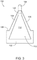
- FIG. 1 shows an exemplary powder capsule (100) that may be created during the 3D printing of various objects.
- Powder capsule (100) may be 3D printed at the same time, and on the same printer base (or "build plate"), as the objects requiring specific powder specifications. Therefore, the powder used to create powder capsule (100) may come from the same powder supply as the powder used to create the objects requiring specific powder specifications; and may thereby accurately serve as a sample of the actual powder that was used to create the 3D printed objects.
- a plurality of objects are 3D printed on the same build plate. In such instances, multiple powder capsules (100) may be 3D printed at the same time, along various locations on the same build plate, as the objects requiring specific powder specifications.
- powder capsule (100) includes a sintered exterior (105) defining a sealed interior (110) housing unsintered powder (112).
- unsintered powder (112) is sealed and encapsulated from the external environment by sintered exterior (105).
- Unsintered powder (112) housed within interior (110) of capsule (100) may be used to provide testing samples to confirm whether objects that were printed using the same powder (112) at the same time powder capsule (100) was printed have specific powder specifications.
- Sintered exterior (105) may thus act as the transportation vessel of unsintered powder (112) before testing is initiated. Additionally, sintered exterior (105) may seal off unsintered powder (112) from outside influences, such as moisture and atmosphere.
- Sintered exterior (105) extends from a base (102) all the way to a cap (104).
- the exterior of base (102) includes a pair of flat surfaces (132) and an upwardly presented shoulder (106).
- a frusto-conical portion (108) extends between upwardly presented shoulder (106) of base (102) and cap (104).
- interior (110) includes a neck down opening (120) directly adjacent to cap (104).
- cap (104) is attached to frusto-conical portion (108) via a relatively thin-walled or otherwise weak connection such that cap (104) may selectively snap off of frusto-conical portion (108) to expose neck down opening (120) to the external environment. As shown in FIG.
- cap (104) when unsintered powder (112) is to be tested, cap (104) may be broken off or otherwise removed from the rest of powder capsule (100) such that neck down opening (120) is exposed to the environment, and unsintered powder (112) may be extracted from interior (110) via neck down opening (120).
- Flat surfaces (132) are configured to be grasped by a pair of clamping members, such as a vise clamp (202) as shown in FIGS. 5A-5C , in order to stabilize powder capsule (100) in preparation of breaking off or otherwise removing cap (104) from the rest of powder capsule (100).
- base (102) also includes an identifier (130) printed on the exterior surface of base (102).
- Identifier (130) have any suitable type of information that would be apparent to one having ordinary skill in the art in view of the teachings herein.
- identifier (130) might include information related to what date capsule (100) was printed, what 3D printer capsule (100) was built on, what portion of build plate was capsule (100) printed, what objects was capsule (100) printed with, how many objects was capsule (100) printed with, how many objects were printed between the current capsule (100) and the next capsule (100), etc.
- identifier (130) may take the form of an alphanumeric code, some other kind of optical code, or any other suitable form as will be apparent to those skilled in the art in view of the teachings herein.
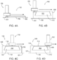
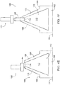
- FIGS. 4A-4F show an exemplary manufacturing process of forming 3D printed powder capsule (100) via a 3D printer (150).
- 3D printer (150) adds a layer of powder on a base plate (101), then traverses across the added layer of powder while sintering the powder to initially form base (102).
- 3D printer (150) may apply layers of powder using any suitable technique as would be apparent to one having ordinary skill in the art in view of the teachings herein. As shown in FIG.
- 3D printer (150) is forming the bottom portion of base (102)
- 3D printer is sintering across the entire cross-sectional area of capsule (100) such that the entire area of the bottom portion of base (102) is sintered, thereby forming the first portion of sintered exterior (105).
- 3D printer (150) repeats this additive process of applying layers of powder and sintering powder to form base (102) until reaching the portion of capsule (100) where base (102) begins to define sealed interior (110). Then, as exemplified between FIGS. 4B-4D , 3D printer (150) traverses across portions of capsule (100) forming sintered exterior (105) while sintering. Next, as shown in FIG. 4C , 3D printer (150) traverses across portions of capsule (100) defining interior (110) without sintering powder (112) deposited within interior (110), thereby leaving a top layer of unsintered powder (114) within the confines of sintered exterior (105). Next, as shown in FIG. 4D , 3D printer (150) traverses across another portion of capsule (100) forming sintered exterior (105) while sintering. Therefore, unsintered powder (112) remains in powder form, while sintered exterior (105) houses powder (112).
- 3D printer (150) may continue to apply layers of powder, sinter portions forming sintered exterior (105), and not sinter top layer of unsintered powder (114) housed within interior (110).
- 3D printer (150) may deposit and sinter layers of powder to form cap (104).
- cap (104) it should be understood that sintered exterior (105) seals and encapsulates unsintered powder (112), thereby protecting powder (112) from the external environment.
- capsule (100) is completed, it should be understood that cap (104), frusto-conical portion (108), and base (102) are of unitary construction.
- capsule (100) With powder (112) protected by sintered exterior (105), capsule (100) may be transported to a testing area in order to test whether powder (112) conforms with desired powder specifications. Alternatively, capsule (100) may be transported to a library or other storage area such that capsule (100) may be retrieved at a later date in the event that it is desired to test powder (112). For instance, if an instrument, tool, implant, or other device that was made in a 3D printing process from a particular batch of powder (112) fails, a capsule (100) containing a powder (112) sample from that same batch of powder (112) may be retrieved from the library or other storage area and tested to determine whether the formulation of the powder (112) led to the failure of the instrument, tool, implant, or other device.
- 3D printer (150) adds an entire layer of powder on top of base plate (101), then traverses above and sinters desired portions of each layer, this is entirely optional.
- 3D printer (150) may add powder on top of base plate (101) and then sinter desired powder using any suitable technique as would be apparent to one having ordinary skill in art in view of the teachings herein.
- 3D printer (150) may add layers of powder on top of base plate (101), then sinter desired sections of powder to print an individual powder capsule (100) between printing desired objects.
- 3D printer (150) may add layers of powder on top of base plate (101), then sinter desired sections of powder to print powder capsule (100) and desired objects simultaneously.
- 3D printer (150) may apply powder and on top of base plate (101) and sinter or not sinter powder using any suitable method that would be apparent to one having ordinary skill in the art in view of the teachings herein.
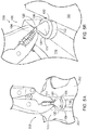
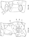
- FIGS. 5A-5E show an exemplary extraction of unsintered powder (112).
- the operator may affix capsule (100) to a clamping member (202), such as a vise clamp, in order to mechanically fasten capsule (100).
- the operator may align opposed flat surfaces (132) into contact with clamping members (202) and actuate clamping member (202) into contact with flat surfaces (132) until capsule (100) is mechanically fastened.
- clamping member (202) includes a vise clamp
- any suitable clamping member (202) may be utilized as would be apparent to one having ordinary skill in the art in view of the teachings herein.
- cap (104) is attached to frusto-conical portion (108) via a relatively thin-walled or otherwise weak connection. Therefore, the operator may grasp cap (104) with gripping device (200) and break off cap (104) from frusto-conical portion (108) at the thin-walled or otherwise weak connection. It should be understood that when cap (104) is removed from capsule (100), powder (112) is exposed to the external environment via neck down opening (120). Next, as shown in FIG.
- the operator may place a storage vial (160) over capsule (100) such that frusto-conical portion (108), and neck down opening (120) are located within the interior of storage vial (160), and an opened rim of storage vial (160) abuts against shoulder (106) of base (102).
- the operator may unfasten capsule (100) from clamping members (202) and flip capsule (100) and vial (160) around such that neck down opening (120) remains within the confines of vial (160).
- Unsintered powder (112) may pour from capsule (100) via neck down opening (120) and transfer into vial (160) under the influence of gravity.
- Capsule (100) may also include external threading configured to mesh with complementary threading on vile (160) such that capsule (100) may screw into engagement with vile (160).
- the operator may remove capsule (100) from vial (160).
- the operator may begin testing unsintered powder (112), or as shown in FIG. 5E , place a cap (162) on vial (160) to further protect powder (112) from the external environment.
- a three-dimensionally printed capsule comprising: (a) a sintered exterior formed from a first powder supply, wherein the sintered exterior defines an interior portion, wherein the sintered exterior comprises: (i) a base, and (ii) a removable cap configured to transition from a fixed position to a detached position, wherein the removable cap is fixed relative to the base in the fixed position, wherein the interior portion is sealed relative to an external environment when the removable cap is in the fixed position, wherein the interior portion is exposed the external environment when the removable cap is in the detached position; and (b) an unsintered powder formed from the first powder supply, wherein the unsintered powder is housed within the sealed interior portion of the sintered exterior, wherein the unsintered powder is protected from the external environment when the removable cap is in the fixed position, wherein the unsintered powder is exposed to the external environment when the removable cap is in the detached position.
- Example 1 The three-dimensionally printed capsule of Example 1, wherein the base comprises a pair of flat surfaces.
- Example 5 The three-dimensionally printed capsule of Example 5, wherein the connecting portion is a frusto-conical shape.
- a method of three-dimensionally printing a powder capsule from a first powder supply wherein the powder capsule comprises (a) a sintered exterior formed of unitary construction, wherein the sintered exterior defines an interior portion; and (b) an unsintered powder housed within the interior portion of the sintered exterior such that the unsintered powder is fully encapsulated by the sintered exterior; the method comprising: (a) depositing a first layer of powder; (b) sintering a first fully contained perimeter of the first layer of powder, as well as an entire interior of the first fully contained perimeter of the first layer of powder; (c) depositing a second layer of powder; (d) sintering a second fully contained perimeter of the second layer of powder without sintering at least a portion of the powder located within the second fully contained perimeter; (e) depositing a third layer of powder; and (f) sintering a third fully contained perimeter of the third layer of powder, as well as an entire interior of the third fully contained perimeter of the third layer of powder.
- Example 10 wherein sintering the first fully contained perimeter of the first layer of powder further comprises sintering the sintered exterior portion, wherein sintering the second fully contained perimeter of the second layer of powder further comprises sintering the sintered exterior portion, wherein sintering the third fully contained perimeter of the third layer of powder further comprises sintering the sintered exterior portion.
- Example 13 The method of Example 13, wherein forming the removable cap further comprises defining a portion of the interior portion.
- a method of three-dimensionally printing a capsule from a first powder supply comprising: (a) depositing a first amount of powder from the first powder supply; (b) sintering the first amount of powder to form a sintered base; (c) depositing a second amount of powder from the first powder supply and a third amount of powder from the first powder supply on top of sintered base; (d) sintering the second amount of powder to form a portion of a sintered side wall connected with the sintered base; (e) depositing a fourth amount of powder from the first powder supply on top of the sintered side wall and the third amount of powder; and (f) sintering the fourth amount of powder to form a portion of a sintered top, wherein the sintered base, the sintered side wall, and the sintered top fully contain the third amount of powder.
- Example 18 The method of Example 18, further comprising sintering a cap on top of the top wall.
Landscapes
- Engineering & Computer Science (AREA)
- Chemical & Material Sciences (AREA)
- Materials Engineering (AREA)
- Manufacturing & Machinery (AREA)
- Physics & Mathematics (AREA)
- Optics & Photonics (AREA)
- Mechanical Engineering (AREA)
- Plasma & Fusion (AREA)
- Life Sciences & Earth Sciences (AREA)
- Analytical Chemistry (AREA)
- Biochemistry (AREA)
- General Health & Medical Sciences (AREA)
- General Physics & Mathematics (AREA)
- Immunology (AREA)
- Pathology (AREA)
- Health & Medical Sciences (AREA)
Applications Claiming Priority (1)
| Application Number | Priority Date | Filing Date | Title |
|---|---|---|---|
| US16/182,819 US20200139621A1 (en) | 2018-11-07 | 2018-11-07 | 3d printed in-process powder capsule for printing material powder characterization |
Publications (1)
| Publication Number | Publication Date |
|---|---|
| EP3656541A1 true EP3656541A1 (fr) | 2020-05-27 |
Family
ID=68502884
Family Applications (1)
| Application Number | Title | Priority Date | Filing Date |
|---|---|---|---|
| EP19207662.8A Withdrawn EP3656541A1 (fr) | 2018-11-07 | 2019-11-07 | Capsule de poudre en cours de procédé imprimée en 3d pour la caractérisation de poudre de matériau d'impression |
Country Status (5)
| Country | Link |
|---|---|
| US (1) | US20200139621A1 (fr) |
| EP (1) | EP3656541A1 (fr) |
| JP (1) | JP7408352B2 (fr) |
| CN (1) | CN111152453B (fr) |
| BR (1) | BR102019022911B1 (fr) |
Cited By (1)
| Publication number | Priority date | Publication date | Assignee | Title |
|---|---|---|---|---|
| DE102023001196A1 (de) | 2023-03-27 | 2023-11-09 | Mercedes-Benz Group AG | Verfahren zur Herstellung eines Bauteils mittels eines additiven Fertigungsverfahrens sowie mindestens einer damit hergestellten Rückstellprobe |
Families Citing this family (2)
| Publication number | Priority date | Publication date | Assignee | Title |
|---|---|---|---|---|
| US11887766B2 (en) * | 2020-08-24 | 2024-01-30 | Ge Aviation Systems Llc | Magnetic component and method of forming |
| US12030119B2 (en) * | 2021-03-31 | 2024-07-09 | Baker Hughes Oilfield Operations Llc | In-situ powder witness coupon |
Citations (3)
| Publication number | Priority date | Publication date | Assignee | Title |
|---|---|---|---|---|
| EP2875933A1 (fr) * | 2013-11-25 | 2015-05-27 | MTU Aero Engines GmbH | Documentation de procédé de fabrication génératif |
| US20160054205A1 (en) * | 2013-04-03 | 2016-02-25 | United Technologies Corporation | Dynamic method of obtaining a sample of materials |
| US20180299359A1 (en) * | 2017-04-18 | 2018-10-18 | General Electric Company | Additive manufacturing test feature including powder sampling capsule |
Family Cites Families (16)
| Publication number | Priority date | Publication date | Assignee | Title |
|---|---|---|---|---|
| GB819758A (en) * | 1956-05-04 | 1959-09-09 | Henri Marcel | A new or improved capsule for bottles and other containers |
| SE350918B (fr) * | 1971-03-26 | 1972-11-13 | Asea Ab | |
| DE19937260B4 (de) * | 1999-08-06 | 2006-07-27 | Eos Gmbh Electro Optical Systems | Verfahren und Vorrichtung zum Herstellen eines dreidimensionalen Objekts |
| ITBO20120103A1 (it) * | 2012-03-05 | 2013-09-06 | Macchiavelli Srl | Capsula per prodotti da infusione |
| US9409108B2 (en) * | 2012-04-06 | 2016-08-09 | Saint-Gobain Performance Pastics Corporation | Modular filter capsule apparatus |
| FR2994113B1 (fr) * | 2012-07-31 | 2017-10-06 | Michelin & Cie | Machine et procede pour la fabrication additive a base de poudre |
| JP6378688B2 (ja) * | 2012-11-01 | 2018-08-22 | ゼネラル・エレクトリック・カンパニイ | 付加製造方法および装置 |
| DE102014116190B3 (de) * | 2014-11-06 | 2016-01-21 | FTAS GmbH | Vorrichtung zum Laserauftragsschweißen zur additiven Fertigung dreidimensionaler Objekte |
| CN107635749A (zh) * | 2015-06-10 | 2018-01-26 | Ipg光子公司 | 多光束增材制造 |
| FR3046367A1 (fr) * | 2015-12-31 | 2017-07-07 | Nantes Ecole Centrale | Dispositif de fabrication additive par projection et fusion de poudre |
| DE102016203955B4 (de) * | 2016-03-10 | 2024-12-12 | Eos Gmbh Electro Optical Systems | Verfahren zur Bereitstellung eines Steuerbefehlssatzes, generative Schichtbauvorrichtung, Steuereinrichtung und Computerprogramm |
| US9821543B1 (en) * | 2016-10-07 | 2017-11-21 | General Electric Company | Additive manufacturing powder handling system |
| US10632732B2 (en) * | 2016-11-08 | 2020-04-28 | 3Dbotics, Inc. | Method and apparatus for making three-dimensional objects using a dynamically adjustable retaining barrier |
| US10773310B2 (en) * | 2017-01-31 | 2020-09-15 | General Electric Company | Additive manufacturing system, article, and method of manufacturing an article |
| JP6878033B2 (ja) * | 2017-02-10 | 2021-05-26 | ローランドディー.ジー.株式会社 | 三次元造形装置 |
| GB2568694B (en) * | 2017-11-23 | 2022-08-24 | Lpw Technology Ltd | Predicting powder degradation in an additive manufacturing process |
-
2018
- 2018-11-07 US US16/182,819 patent/US20200139621A1/en not_active Abandoned
-
2019
- 2019-10-31 BR BR102019022911-0A patent/BR102019022911B1/pt active IP Right Grant
- 2019-11-06 CN CN201911077626.1A patent/CN111152453B/zh active Active
- 2019-11-06 JP JP2019201309A patent/JP7408352B2/ja active Active
- 2019-11-07 EP EP19207662.8A patent/EP3656541A1/fr not_active Withdrawn
Patent Citations (3)
| Publication number | Priority date | Publication date | Assignee | Title |
|---|---|---|---|---|
| US20160054205A1 (en) * | 2013-04-03 | 2016-02-25 | United Technologies Corporation | Dynamic method of obtaining a sample of materials |
| EP2875933A1 (fr) * | 2013-11-25 | 2015-05-27 | MTU Aero Engines GmbH | Documentation de procédé de fabrication génératif |
| US20180299359A1 (en) * | 2017-04-18 | 2018-10-18 | General Electric Company | Additive manufacturing test feature including powder sampling capsule |
Cited By (1)
| Publication number | Priority date | Publication date | Assignee | Title |
|---|---|---|---|---|
| DE102023001196A1 (de) | 2023-03-27 | 2023-11-09 | Mercedes-Benz Group AG | Verfahren zur Herstellung eines Bauteils mittels eines additiven Fertigungsverfahrens sowie mindestens einer damit hergestellten Rückstellprobe |
Also Published As
| Publication number | Publication date |
|---|---|
| BR102019022911A2 (pt) | 2020-05-26 |
| JP2020075502A (ja) | 2020-05-21 |
| CN111152453B (zh) | 2023-08-01 |
| BR102019022911B1 (pt) | 2024-01-16 |
| US20200139621A1 (en) | 2020-05-07 |
| CN111152453A (zh) | 2020-05-15 |
| JP7408352B2 (ja) | 2024-01-05 |
Similar Documents
| Publication | Publication Date | Title |
|---|---|---|
| EP3656541A1 (fr) | Capsule de poudre en cours de procédé imprimée en 3d pour la caractérisation de poudre de matériau d'impression | |
| JP6949866B2 (ja) | 再充填可能な電子ベイピング装置用の再充填容器 | |
| EP1973658A1 (fr) | Cassette d'emballage pour supports de réactifs | |
| WO2017162885A1 (fr) | Procédé de transport de produits à température dirigée, récipient de transport, dispositif de conditionnement et logiciel de commande | |
| US9579179B2 (en) | System and method for packaging dental ingots | |
| AU2014201270B2 (en) | Grain bin sensor cable forming method and apparatus | |
| JPH04215967A (ja) | 容器ユニット及びこの容器ユニットの製造方法 | |
| KR20160074440A (ko) | 약액 수납 용기 및 그 드라이 에어 치환 방법 | |
| JP2019526502A (ja) | 液体充填カプセルの製造方法および装置 | |
| EP3081507B1 (fr) | Emballage-coque permettant de loger simultanément un contenant d'emballage pour contenu de type recharge ou cartouche et un boîtier destiné à recevoir celui-ci | |
| US20200165022A1 (en) | An apparatus and method for automated sorting and enveloping of homogeneous and/or heterogeneous substances | |
| EP4313547B1 (fr) | Coupon témoin de poudre in situ | |
| CN107108104B (zh) | 容器、封装体及关闭容器的方法 | |
| US20200382685A1 (en) | Real time imaging and wireless transmission system and method for material handling equipment | |
| WO2023126546A1 (fr) | Récipient pour le stockage et l'analyse irm de cerveaux en pathologie | |
| CA2561699A1 (fr) | Mecanisme refermable pour distributeur | |
| DE10054161C2 (de) | Verpackung für Halbleiterscheiben und Verfahren zu ihrer Herstellung | |
| Lee | Batch Processing of Brain Tissue Sections for Millimeter-Scale Serial Section Transmission Electron Microscopy Connectomics | |
| EP3081302A1 (fr) | Boîtier pouvant être tempéré pour récipient contenant un liquide réactif | |
| JP2006188266A (ja) | 除湿内袋を収納した気密容器 | |
| KR20140001016U (ko) | 화장품용 몰드에 적용되는 이탈방지 자석몰드장치 | |
| EP1520803A3 (fr) | Emballage pour produits pharmaceutiques ou médicaux, procédé et dispositif pour le fabriquer et le remplir | |
| DE102007024071A1 (de) | Dielektrizitätsmesseinrichtung | |
| IT202100000644A1 (it) | Contenitore per l’erogazione di polveri o prodotti granulari ed assieme comprendente il contenitore | |
| DE102007026646A1 (de) | Dielektrizitätsmesseinrichtung |
Legal Events
| Date | Code | Title | Description |
|---|---|---|---|
| PUAI | Public reference made under article 153(3) epc to a published international application that has entered the european phase |
Free format text: ORIGINAL CODE: 0009012 |
|
| STAA | Information on the status of an ep patent application or granted ep patent |
Free format text: STATUS: THE APPLICATION HAS BEEN PUBLISHED |
|
| AK | Designated contracting states |
Kind code of ref document: A1 Designated state(s): AL AT BE BG CH CY CZ DE DK EE ES FI FR GB GR HR HU IE IS IT LI LT LU LV MC MK MT NL NO PL PT RO RS SE SI SK SM TR |
|
| AX | Request for extension of the european patent |
Extension state: BA ME |
|
| STAA | Information on the status of an ep patent application or granted ep patent |
Free format text: STATUS: REQUEST FOR EXAMINATION WAS MADE |
|
| 17P | Request for examination filed |
Effective date: 20201126 |
|
| RBV | Designated contracting states (corrected) |
Designated state(s): AL AT BE BG CH CY CZ DE DK EE ES FI FR GB GR HR HU IE IS IT LI LT LU LV MC MK MT NL NO PL PT RO RS SE SI SK SM TR |
|
| STAA | Information on the status of an ep patent application or granted ep patent |
Free format text: STATUS: EXAMINATION IS IN PROGRESS |
|
| 17Q | First examination report despatched |
Effective date: 20210720 |
|
| RIC1 | Information provided on ipc code assigned before grant |
Ipc: G01N 1/28 20060101ALI20220511BHEP Ipc: B22F 10/20 20210101ALI20220511BHEP Ipc: B22F 5/10 20060101ALI20220511BHEP Ipc: B33Y 10/00 20150101ALI20220511BHEP Ipc: B33Y 80/00 20150101ALI20220511BHEP Ipc: B29C 64/386 20170101ALI20220511BHEP Ipc: B22F 3/105 20060101ALI20220511BHEP Ipc: G01N 1/04 20060101ALI20220511BHEP Ipc: B29C 64/153 20170101AFI20220511BHEP |
|
| GRAP | Despatch of communication of intention to grant a patent |
Free format text: ORIGINAL CODE: EPIDOSNIGR1 |
|
| STAA | Information on the status of an ep patent application or granted ep patent |
Free format text: STATUS: GRANT OF PATENT IS INTENDED |
|
| INTG | Intention to grant announced |
Effective date: 20220621 |
|
| STAA | Information on the status of an ep patent application or granted ep patent |
Free format text: STATUS: THE APPLICATION IS DEEMED TO BE WITHDRAWN |
|
| 18D | Application deemed to be withdrawn |
Effective date: 20221103 |