EP3656633B1 - Voiture de véhicule ferroviaire - Google Patents
Voiture de véhicule ferroviaire Download PDFInfo
- Publication number
- EP3656633B1 EP3656633B1 EP19211245.6A EP19211245A EP3656633B1 EP 3656633 B1 EP3656633 B1 EP 3656633B1 EP 19211245 A EP19211245 A EP 19211245A EP 3656633 B1 EP3656633 B1 EP 3656633B1
- Authority
- EP
- European Patent Office
- Prior art keywords
- support
- box
- roof
- railway vehicle
- vehicle car
- Prior art date
- Legal status (The legal status is an assumption and is not a legal conclusion. Google has not performed a legal analysis and makes no representation as to the accuracy of the status listed.)
- Active
Links
Images

Classifications
-
- B—PERFORMING OPERATIONS; TRANSPORTING
- B61—RAILWAYS
- B61D—BODY DETAILS OR KINDS OF RAILWAY VEHICLES
- B61D17/00—Construction details of vehicle bodies
- B61D17/04—Construction details of vehicle bodies with bodies of metal; with composite, e.g. metal and wood body structures
- B61D17/12—Roofs
-
- B—PERFORMING OPERATIONS; TRANSPORTING
- B61—RAILWAYS
- B61C—LOCOMOTIVES; MOTOR RAILCARS
- B61C17/00—Arrangement or disposition of parts; Details or accessories not otherwise provided for; Use of control gear and control systems
-
- B—PERFORMING OPERATIONS; TRANSPORTING
- B61—RAILWAYS
- B61D—BODY DETAILS OR KINDS OF RAILWAY VEHICLES
- B61D1/00—Carriages for ordinary railway passenger traffic
Definitions
- Rail vehicle cars of the aforementioned type are known, see for example document US 2012/193493 A1 .
- Primary brackets are generally used to secure the electrical equipment trunk to the roof of this car.
- the pavilion is generally made of aluminum.
- the primary supports are exposed to the fire. Since the primary supports are made of a metallic material, and therefore a heat conductor, the part of the pavilion adjacent to the primary support can reach or exceed the melting temperature of the aluminum.
- the roof may sag around the primary supports under the effect of the weight of the trunk. This sagging can then create a breach in the pavilion, forming a passage for flames, which presents dangers to passengers.
- the object of the invention is in particular to remedy this drawback, by limiting the risk of a breach on the pavilion in the event of a fire thereon.
- the invention relates to a rail vehicle car of the aforementioned type comprising at least one secondary support interposed between the trunk and the roof, the secondary support being arranged in a central part of the trunk and being able to support the weight. of the trunk in the event of the roof sag at the location of said primary support.
- Car 10 has four vertical walls (not shown in the figure) defining a substantially rectangular space (not shown in the figure), each vertical wall extending in the direction of the vertical axis Z between a lower end and a upper edge.
- Car 10 furthermore comprises a horizontal roof 16 connecting the upper edges of the four walls, and a floor (not shown in the figure) connecting the lower ends of the four walls.
- the pavilion 16 is made of a metallic material, for example aluminum.
- the pavilion 16 comprises an upper surface 18 and a lower surface (not shown in the figure).
- the upper surface 18 comprises at least one fixing rail 22 on which fixing elements are intended to be fixed.
- the fixing rails 22 are arranged substantially parallel to one another, and preferably extend all along the length of the roof 16 along the longitudinal axis X.
- the car 10 also includes a trunk 24 mounted on the upper surface 18 of the roof 16, and at least one primary support 26 interposed between the trunk 24 and the roof 16 to support the trunk 24.
- the chest 24 is for example suitable for housing electronic equipment.
- the box 24 is adapted to house ventilation and / or air conditioning components.
- the trunk 24 is capable of being moved between a rest position when the flag 16 does not have sagging, and a plurality of lowered positions when the flag 16 has sagging.
- the box 24 has four vertical sides 28 each extending in the vertical direction Z between a lower end and an upper end, a horizontal lower wall 30 connecting the lower ends of the four sides 28, and a horizontal upper wall 32 connecting the upper ends. of the four flanks 28.
- each longitudinal vertical flank extends parallel to the longitudinal direction X between two longitudinal ends.
- the lower wall 30 has a peripheral part 34 and a central part 36.
- the primary supports 26 are arranged in the peripheral part 34 of the box 24.
- the primary supports 26 are adapted to support the weight of the box 24.
- the car 10 has two primary supports 26 on each longitudinal side 28. More particularly, each longitudinal sidewall 28 carries a primary support 26 at each of its longitudinal ends.
- Each primary support 26 is fixed, on the one hand, to one of the fixing rails 22 by a first fixing element 38, and on the other hand, to one of the vertical sides 28.
- the first fixing element 38 comprises for example a screw-nut system.
- the car 10 also has a protection plate 40 for each primary support 26.
- the protection plate 40 is arranged. on the roof 16 between two fixing rails 22.
- the protection plate 40 surrounds the primary support 26 corresponding.
- the protection plate 40 is intended in particular to thermally insulate the fixing rail 22 by matching the shape of the primary support 26.
- the car 10 also includes at least one secondary support 42 interposed between the trunk 24 and the roof 16.
- the secondary support 42 is adapted, in the event of the roof 16 sagging in the area of the primary supports 26, to support the weight of the trunk. 24.
- the secondary supports 42 are arranged in the central part 36 of the lower wall 30.
- the car 10 comprises two secondary supports 42 arranged symmetrically with respect to a plane of symmetry of the roof 16, parallel to the steering vertical Z and the longitudinal direction X.
- the secondary supports 42 are made of a material which has a higher melting point than that of the primary supports 26. They are for example made of stainless steel.
- the thickness of the secondary supports 42 is between 1 mm and 10 mm, in particular between 2 mm and 8 mm, and is preferably equal to 4 mm.
- Each secondary support 42 is fixed to the roof 16 by a respective second fixing element 44.
- Each second fixing element 44 comprises for example a screw-nut system, and may be identical or different from the first fixing element 38.
- Each secondary support 42 has a “U” shape, the “U” opening of each secondary support being oriented away from the other secondary support.
- the “U” openings of the secondary supports 42 are arranged one opposite the other.
- It comprises a lower rim 46, an upper rim 48, and a vertical wall 50 connecting said lower 46 and upper 48 rims.
- the lower rim 46 is fixed to the roof 16 by the second fastening element 44.
- the upper rim 48 is arranged opposite the trunk 24. It is arranged substantially parallel to the lower rim 46.
- the upper rim 48 has a shape substantially identical to that of the lower rim 46. In the preferred configuration, the upper rim 48 has the same dimensions as the lower rim 46.
- the vertical wall 50 of the secondary support 42 has, in the vertical direction Z, a height less than the distance between the box 24 and the roof 16 when the flag 16 is in the rest position. In other words, when the flag 16 occupies its rest position, a vertical spacing 52 occurs between the lower wall 30 and the upper rim 48.
- the secondary support 42 further comprises at least one reinforcing rib 54 projecting perpendicularly from the vertical wall 50, and extends substantially over the entire transverse width of the lower and upper flanges 46, 48.
- the reinforcing ribs 54 are suitable for reinforcing the structure of the secondary support 42 in the vertical direction Z.
- the secondary support 42 comprises two reinforcing ribs 54.
- the car 10 further comprises a thermally insulating strip 56 disposed on the upper surface of the upper rim 48 facing the trunk 24.
- the insulating strip 56 is suitable for reducing the transfer of heat between the trunk 24 and the supports. secondary 42. When the box 24 is in the rest position, the insulating strip 56 is away from the lower wall 30 of the box 24.
- the flag 16 When there is no sagging of the flag 16, the flag 16 is in the rest position.
- the trunk 24 is supported by the primary supports 26, and is away from the secondary supports 42.
- the primary supports 26 When there is a significant increase in temperature near the pavilion 16, due for example to the presence of a fire, the primary supports 26 are exposed to heat. Being made of a metallic material, the primary supports 26 transfer heat to the pavilion 16 and thus heat it up.
- the pavilion 16 is made of aluminum which has a melting point of 660 ° C. When the temperature near the primary supports 26 of the box 24 approaches this melting temperature, the roof 16 softens and collapses under the effect of the weight of the box 24 near the primary supports 26.
- the box 24 therefore begins to descend, and the lower wall 30 approaches the secondary supports 42. In doing so, the vertical distance 52 decreases until the box 24 comes into contact with the upper edges 48.
- the secondary supports 42 being less exposed to heat and in particular to radiation, the part of the pavilion 16 in their proximity remains solid and capable of supporting the weight of the box 24.
- the upper edges 48 exert a supporting force on the box 24, and the descent of the trunk 24 is stopped.
- the invention makes it possible to obtain a stronger attachment of the trunk 24 during a fire and makes the car more reliable.
Landscapes
- Engineering & Computer Science (AREA)
- Mechanical Engineering (AREA)
- Life Sciences & Earth Sciences (AREA)
- Wood Science & Technology (AREA)
- Transportation (AREA)
- Automation & Control Theory (AREA)
- Fittings On The Vehicle Exterior For Carrying Loads, And Devices For Holding Or Mounting Articles (AREA)
- Body Structure For Vehicles (AREA)
- Electric Propulsion And Braking For Vehicles (AREA)
Description
- La présente invention concerne une voiture de véhicule ferroviaire, du type comprenant :
- un pavillon,
- un coffre monté sur le pavillon,
- au moins un support primaire de coffre, interposé entre le coffre et le pavillon, ledit support primaire étant disposé dans une partie périphérique du coffre et étant destiné à soutenir le poids du coffre.
- Des voitures de véhicule ferroviaire du type précité sont connues, voir par exemple le document
US 2012/193493 A1 . Les supports primaires sont généralement utilisés pour fixer le coffre d'équipements électriques sur le pavillon de cette voiture. - Ces voitures connues ne donnent toutefois pas entière satisfaction.
- Le pavillon est généralement réalisé en aluminium. En cas d'incendie sur ce pavillon, les supports primaires se retrouvent exposés au feu. Les supports primaires étant réalisés en un matériau métallique, donc conducteur de chaleur, la partie du pavillon voisine du support primaire peut atteindre ou surpasser la température de fusion de l'aluminium. Dans ce cas, le pavillon peut s'affaisser autour des supports primaires sous l'effet du poids du coffre. Cet affaissement peut alors créer une brèche dans le pavillon, formant un passage pour des flammes, ce qui présente des dangers pour les passagers.
- L'invention a notamment pour but de remédier à cet inconvénient, en limitant le risque de brèche sur le pavillon en cas d'incendie sur celui-ci.
- A cet effet, l'invention a pour objet une voiture de véhicule ferroviaire de type précité comportant au moins un support secondaire interposé entre le coffre et le pavillon, le support secondaire étant disposé dans une partie centrale du coffre et étant propre à soutenir le poids du coffre en cas d'affaissement du pavillon à l'endroit dudit support primaire.
- Selon des modes de réalisation particuliers de l'invention, la voiture de véhicule ferroviaire présente en outre l'une ou plusieurs des caractéristiques suivantes, prise(s) isolément ou suivant toute(s) combinaison(s) techniquement possible(s) :
- le support secondaire est réalisé en un matériau présentant une température de fusion supérieure à celle du support primaire ;
- le support secondaire est réalisé en inox ;
- la voiture de véhicule ferroviaire comporte une bande en matériau thermiquement isolant interposée entre le support secondaire et le coffre ;
- un écartement vertical est ménagé entre le support secondaire et le coffre lorsque le pavillon ne présente pas d'affaissement ;
- le pavillon comporte des rails de fixation, chaque support primaire étant fixé sur l'un des rails de fixation ;
- chaque support secondaire est fixé à au moins un des rails de fixation ; et
- chaque support secondaire présente une forme en « U » définie par un rebord inférieur fixé au pavillon, un rebord supérieur disposé en regard du coffre, et une paroi verticale reliant les rebords inférieur et supérieur, le support secondaire comportant des nervures de renforts à son intérieur, reliant les rebords inférieur et supérieur et s'étendant perpendiculairement à la paroi verticale.
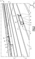
- D'autres caractéristiques et avantages de l'invention apparaîtront à la lecture de la description qui va suivre, donnée uniquement à titre d'exemple et faite en se référant aux dessins annexés, dans lesquels :
- [
Fig 1 ] laFigure 1 est une vue partielle en perspective d'une voiture selon l'invention, un coffre étant monté sur le pavillon de la voiture, et - [
Fig 2 ] laFigure 2 est une vue en perspective de supports secondaires équipant la voiture de laFigure 1 . - Dans la suite, les termes d'orientation s'entendent en référence au repère d'orientation usuel des véhicules ferroviaires, représenté sur la
Figure 1 , et dans lequel on distingue : - un axe longitudinal X, orienté de l'arrière vers l'avant, selon le sens de marche de la voiture 10,
- un axe transversal Y, perpendiculaire à l'axe longitudinal, orienté de la droite vers la gauche et formant avec l'axe X un plan horizontal, et
- un axe vertical Z, perpendiculaire au plan horizontal, orienté du bas vers le haut.
- On a représenté sur la
Figure 1 une voiture 10 d'un véhicule ferroviaire selon un exemple de mode de réalisation de l'invention. La voiture 10 comporte quatre parois verticales (non-représentées sur la figure) définissant un espace (non-représenté sur la figure) sensiblement rectangulaire, chaque paroi verticale s'étendant dans la direction de l'axe vertical Z entre une extrémité inférieure et un bord supérieur. La voiture 10 comporte par ailleurs un pavillon 16 horizontal reliant les bords supérieurs des quatre parois, et un sol (non-représenté sur la figure) reliant les extrémités inférieures des quatre parois. - Le pavillon 16 est réalisé en un matériau métallique, par exemple en aluminium.
- Le pavillon 16 comprend une surface supérieure 18 et une surface inférieure (non-représentée sur la figure).
- La surface supérieure 18 comporte au moins un rail de fixation 22 sur lequel des éléments de fixation sont destinés à être fixés. Les rails de fixation 22 sont disposés sensiblement parallèlement l'un de l'autre, et s'étendent de préférence tout le long du pavillon 16 selon l'axe longitudinal X.
- La voiture 10 comporte également un coffre 24 monté sur la surface supérieure 18 du pavillon 16, et au moins un support primaire 26 interposé entre le coffre 24 et le pavillon 16 pour supporter le coffre 24.
- Le coffre 24 est par exemple adapté pour loger des équipements électroniques. Dans une variante, le coffre 24 est adapté pour loger des composants de ventilation et/ou de climatisation.
- Le coffre 24 est susceptible d'être déplacé entre une position de repos lorsque le pavillon 16 ne présente pas d'affaissement, et une pluralité de positions baissées lorsque le pavillon 16 présente l'affaissement.
- Le coffre 24 comporte quatre flancs verticaux 28 s'étendant chacun dans la direction verticale Z entre une extrémité inférieure et une extrémité supérieure, une paroi inférieure 30 horizontale reliant les extrémités inférieures des quatre flancs 28, et une paroi supérieure 32 horizontale reliant les extrémités supérieures des quatre flancs 28.
- Parmi les quatre flancs verticaux 28, deux flancs verticaux dits longitudinaux s'étendent dans un plan parallèle à la direction verticale Z et à la direction longitudinale X. Chaque flanc vertical longitudinal s'étend parallèlement à la direction longitudinale X entre deux extrémités longitudinales.
- La paroi inférieure 30 comporte une partie périphérique 34 et une partie centrale 36.
- Les supports primaires 26 sont disposés dans la partie périphérique 34 du coffre 24. Les supports primaires 26 sont adaptés pour soutenir le poids du coffre 24.
- Dans la configuration préférée, comme représenté sur la
figure 1 , la voiture 10 comporte deux supports primaires 26 sur chaque flanc 28 longitudinal. Plus particulièrement, chaque flanc 28 longitudinal porte un support primaire 26 à chacune de ses extrémités longitudinales. - Chaque support primaire 26 est fixé, d'une part, à l'un des rails de fixation 22 par un premier élément de fixation 38, et d'autre part, à l'un des flancs verticaux 28.
- Le premier élément de fixation 38 comporte par exemple un système de vis-écrou.
- Dans la configuration préférée, la voiture 10 comporte également une plaque de protection 40 pour chaque support primaire 26. La plaque de protection 40 est disposée sur le pavillon 16 entre deux rails de fixation 22. La plaque de protection 40 entoure le support primaire 26 correspondant. La plaque de protection 40 est notamment destinée à isoler thermiquement le rail de fixation 22 en épousant la forme du support primaire 26.
- La voiture 10 comporte également au moins un support secondaire 42 interposé entre le coffre 24 et le pavillon 16. Le support secondaire 42 est adapté, en cas d'affaissement du pavillon 16 dans la zone des supports primaires 26, pour soutenir le poids du coffre 24.
- En référence à la
figure 2 , les supports secondaires 42 sont disposé dans la partie centrale 36 de la paroi inférieure 30. Dans la configuration préférée, la voiture 10 comporte deux supports secondaires 42 disposés de manière symétrique par rapport à un plan de symétrie du pavillon 16, parallèle à la direction verticale Z et à la direction longitudinale X. - Les supports secondaires 42 sont réalisés en un matériau qui présente une température de fusion plus haute que celle des supports primaires 26. Ils sont par exemple réalisés en inox.
- L'épaisseur des supports secondaires 42 est comprise entre 1 mm et 10 mm, notamment entre 2 mm et 8 mm, et est de préférence égale à 4 mm.
- Chaque support secondaire 42 est fixé sur le pavillon 16 par un deuxième élément de fixation 44 respectif. Chaque deuxième élément de fixation 44 comporte par exemple un système de vis-écrou, et peut être identique ou différent du premier élément de fixation 38.
- Chaque support secondaire 42 présente une forme en « U », l'ouverture de « U » de chaque support secondaire étant orientée à l'opposé de l'autre support secondaire. Dans une variante, les ouvertures de « U » des supports secondaires 42 sont disposées l'un en regard de l'autre.
- Il comporte un rebord inférieur 46, un rebord supérieur 48, et une paroi verticale 50 reliant lesdits rebords inférieur 46 et supérieur 48.
- Le rebord inférieur 46 est fixé au pavillon 16 par le deuxième élément de fixation 44.
- Le rebord supérieur 48 est disposé en regard du coffre 24. Il est disposé sensiblement en parallèle au rebord inférieur 46.
- Le rebord supérieur 48 présente une forme sensiblement identique à celle du rebord inférieure 46. Dans la configuration préférée, le rebord supérieur 48 présente les mêmes dimensions que le rebord inférieur 46.
- La paroi verticale 50 du support secondaire 42 présente, dans la direction verticale Z, une hauteur inférieure à la distance entre le coffre 24 et le pavillon 16 lorsque le pavillon 16 est en position de repos. En d'autres termes, lorsque le pavillon 16 occupe sa position de repos, un écartement vertical 52 se présente entre la paroi inférieure 30 et le rebord supérieur 48.
- Le support secondaire 42 comporte en outre au moins une nervure de renforts 54 faisant saillie perpendiculairement à partir de la paroi verticale 50, et s'étend sensiblement sur toute la largeur transversale des rebords inférieur et supérieur 46, 48. Les nervures de renforts 54 sont propres à renforcer la structure du support secondaire 42 dans la direction verticale Z.
- Dans la configuration préférée, comme visible sur la
figure 2 , le support secondaire 42 comporte deux nervures de renforts 54. - Dans une variante, la voiture 10 comporte en outre une bande 56 thermiquement isolante disposée sur la surface supérieure du rebord supérieur 48 en regard du coffre 24. La bande isolante 56 est propre à réduire le transfert de la chaleur entre le coffre 24 et les supports secondaires 42. Lorsque le coffre 24 est en position de repos, la bande isolante 56 est à l'écart de la paroi inférieure 30 du coffre 24.
- Le fonctionnement du dispositif selon l'invention est décrit ci-dessous.
- Lorsqu'il n'y a pas d'affaissement du pavillon 16, le pavillon 16 est en position de repos. Le coffre 24 est soutenu par les supports primaires 26, et est à l'écart des supports secondaires 42.
- Lorsqu'il y a une augmentation importante de la température à proximité du pavillon 16, due par exemple à la présence d'un feu, les supports primaires 26 sont exposés à la chaleur. Etant réalisés en matériau métallique, les supports primaires 26 transfèrent de la chaleur vers le pavillon 16 et ainsi le réchauffent.
- Le pavillon 16 est réalisé en aluminium qui présente une température de fusion à 660°C. Lorsque la température à proximité des supports primaires 26 du coffre 24 s'approche de cette température de fusion, le pavillon 16 se ramollit, et s'affaisse sous l'effet du poids du coffre 24 à proximité des supports primaires 26.
- Le coffre 24 commence donc à descendre, et la paroi inférieure 30 s'approche des supports secondaires 42. Ce faisant, l'écartement vertical 52 diminue jusqu'à ce que le coffre 24 entre en contact avec les rebords supérieurs 48.
- Les supports secondaires 42 étant moins exposés à la chaleur et notamment au rayonnement, la partie du pavillon 16 à leurs proximités reste solide et apte à soutenir le poids du coffre 24. Ainsi, les rebords supérieurs 48 exercent une force supportrice sur le coffre 24, et la descente du coffre 24 est arrêtée.
- Grâce à l'invention décrite ci-dessus, les risques qu'une brèche soit créée sur le pavillon 16 suite à un incendie et que des flammes passent par l'ouverture sont réduits, ce qui offre une meilleure sécurité aux passagers.
- De plus, l'invention permet d'obtenir une fixation du coffre 24 plus solide lors d'un incendie et rend la voiture plus fiable.
Claims (8)
- Voiture (10) de véhicule ferroviaire, comprenant :- un pavillon (16),- un coffre (24) monté sur le pavillon (16),- au moins un support primaire (26) de coffre (24), interposé entre le coffre (24) et le pavillon (16), ledit support primaire (26) étant disposé dans une partie périphérique (34) du coffre (24) et étant destiné à soutenir le poids du coffre (24),caractérisé en ce qu'elle comporte au moins un support secondaire (42) interposé entre le coffre (24) et le pavillon (16), le support secondaire (42) étant disposé dans une partie centrale (36) du coffre (24) et étant propre à soutenir le poids du coffre (24) en cas d'affaissement du pavillon (16) à l'endroit dudit support primaire (26).
- Voiture (10) de véhicule ferroviaire selon la revendication 1, dans laquelle le support secondaire (42) est réalisé en un matériau présentant une température de fusion supérieure à celle du support primaire (26).
- Voiture (10) de véhicule ferroviaire selon la revendication 1 ou 2, dans laquelle le support secondaire (42) est réalisé en inox.
- Voiture (10) de véhicule ferroviaire selon l'une quelconque des revendications 1 à 3, comportant une bande (56) en matériau thermiquement isolant interposée entre le support secondaire (42) et le coffre (24).
- Voiture (10) de véhicule ferroviaire selon l'une quelconque des revendications 1 à 4, dans laquelle un écartement vertical (52) est ménagé entre le support secondaire (42) et le coffre (24) lorsque le pavillon (16) ne présente pas d'affaissement.
- Voiture (10) de véhicule ferroviaire selon l'une quelconque des revendications 1 à 5, dans laquelle le pavillon (16) comporte des rails de fixation (22), chaque support primaire (26) étant fixé sur l'un des rails de fixation (22).
- Voiture (10) de véhicule ferroviaire selon la revendication 6, dans laquelle chaque support secondaire (42) est fixé à au moins un des rails de fixation (22).
- Voiture (10) de véhicule ferroviaire selon l'une quelconque des revendications 1 à 7, dans laquelle chaque support secondaire (42) présente une forme en « U » définie par un rebord inférieur (46) fixé au pavillon (16), un rebord supérieur (48) disposé en regard du coffre (24), et une paroi verticale (50) reliant les rebords inférieur (46) et supérieur (48), le support secondaire (42) comportant des nervures de renforts (54) à son intérieur, reliant les rebords inférieur (46) et supérieur (48) et s'étendant perpendiculairement à la paroi verticale (50).
Applications Claiming Priority (1)
| Application Number | Priority Date | Filing Date | Title |
|---|---|---|---|
| FR1871840A FR3088886B1 (fr) | 2018-11-26 | 2018-11-26 | Voiture de véhicule ferroviaire |
Publications (2)
| Publication Number | Publication Date |
|---|---|
| EP3656633A1 EP3656633A1 (fr) | 2020-05-27 |
| EP3656633B1 true EP3656633B1 (fr) | 2021-02-24 |
Family
ID=65951736
Family Applications (1)
| Application Number | Title | Priority Date | Filing Date |
|---|---|---|---|
| EP19211245.6A Active EP3656633B1 (fr) | 2018-11-26 | 2019-11-25 | Voiture de véhicule ferroviaire |
Country Status (4)
| Country | Link |
|---|---|
| US (1) | US20200164901A1 (fr) |
| EP (1) | EP3656633B1 (fr) |
| ES (1) | ES2870575T3 (fr) |
| FR (1) | FR3088886B1 (fr) |
Families Citing this family (1)
| Publication number | Priority date | Publication date | Assignee | Title |
|---|---|---|---|---|
| DE102021214851A1 (de) | 2021-12-21 | 2023-06-22 | Siemens Mobility GmbH | Anordnung und Verfahren zur Befestigung eines Gerüsts |
Family Cites Families (5)
| Publication number | Priority date | Publication date | Assignee | Title |
|---|---|---|---|---|
| US4318350A (en) * | 1979-12-03 | 1982-03-09 | The Budd Company | Overhead wiring arrangement for a railway car |
| US20120193493A1 (en) * | 2011-02-01 | 2012-08-02 | Klaus Rekasch | Rail vehicle having an installation housing secured by means of a bracket |
| DE102013218772B3 (de) * | 2013-09-19 | 2015-02-05 | Siemens Aktiengesellschaft | Befestigungsanordnung zur Anbindung eines Gerätecontainers an ein Schienenfahrzeugdach und damit ausgestattetes Schienenfahrzeug |
| DE102014206462A1 (de) * | 2014-04-03 | 2015-10-08 | Bombardier Transportation Gmbh | Wagenkasten für ein Schienenfahrzeug mit speziell ausgebildetem Tragelement für ein Dach |
| FR3050726B1 (fr) * | 2016-04-29 | 2018-05-25 | Alstom Transport Technologies | Coffre pour equipement electrique et vehicule ferroviaire comprenant un tel coffre |
-
2018
- 2018-11-26 FR FR1871840A patent/FR3088886B1/fr not_active Expired - Fee Related
-
2019
- 2019-11-21 US US16/691,550 patent/US20200164901A1/en not_active Abandoned
- 2019-11-25 ES ES19211245T patent/ES2870575T3/es active Active
- 2019-11-25 EP EP19211245.6A patent/EP3656633B1/fr active Active
Non-Patent Citations (1)
| Title |
|---|
| None * |
Also Published As
| Publication number | Publication date |
|---|---|
| FR3088886A1 (fr) | 2020-05-29 |
| US20200164901A1 (en) | 2020-05-28 |
| ES2870575T3 (es) | 2021-10-27 |
| EP3656633A1 (fr) | 2020-05-27 |
| FR3088886B1 (fr) | 2020-12-11 |
Similar Documents
| Publication | Publication Date | Title |
|---|---|---|
| FR3031491A1 (fr) | ||
| EP3096999B1 (fr) | Structure de caisse d'un véhicule automobile avec renforts de répartition des efforts liés à un amortisseur arrière du véhicule | |
| EP3057851A2 (fr) | Structure de bavolet de véhicule automobile | |
| EP3656633B1 (fr) | Voiture de véhicule ferroviaire | |
| FR2933059A1 (fr) | Insert de rigidification pour caisse de vehicule automobile | |
| FR3070645A1 (fr) | Ensemble pare-chocs pour vehicule automobile | |
| EP2977287B1 (fr) | Parois structurelles pour une caisse de véhicule ferroviaire, procédé d'assemblage et véhicule ferroviaire associés | |
| EP1054801A1 (fr) | Agencement de la partie inferieure de l'habitacle d'un vehicule automobile | |
| EP4267419A1 (fr) | Structure de soubassement pour véhicule automobile | |
| FR2853955A1 (fr) | Dispositif de supportage d'un moufle de four de cuisson | |
| EP1580102B1 (fr) | Procédé d'assemblage d'un pavillon en aluminium sur les flancs d'une caisse d'un véhicule automobile et pavillon en aluminium pour véhicle automobile | |
| EP3829963B1 (fr) | Vehicule avec deflecteur arriere sous-plancher montrant un chanfrein | |
| FR2867740A1 (fr) | Toit de vehicule automobile et vehicule automobile comportant un tel toit | |
| EP1004497A1 (fr) | Carrosserie avant de véhicule assurant la protection des piétons en cas de choc frontal | |
| EP3097000B1 (fr) | Structure de caisse d'un véhicule automobile avec renforts de répartition des efforts liés à un amortisseur arrière du véhicule | |
| EP3219850B1 (fr) | Système de traverse à coque amélioré et tronçon de voie ferrée integrant un tel système | |
| WO2011055078A1 (fr) | Partie avant de vehicule automobile comprenant une traverse inferieure de baie supportant le bord inferieur d'un pare-brise | |
| EP4124508B1 (fr) | Coffre de toit et véhicule équipé d'un tel coffre | |
| EP4244978B1 (fr) | Plaque de support perfectionnée pour panneau photovoltaïque | |
| FR3088269A1 (fr) | Support monobloc de fixation d'un enrouleur de ceinture de securite sur une doublure de custode d'un vehicule automobile | |
| EP3315377B1 (fr) | Structure de caisse pour un véhicule sur rails et procédé de fabrication d'une telle structure de caisse | |
| EP4501680A1 (fr) | Carénage comprenant un support d'isolation thermique | |
| EP3585676B1 (fr) | Dispositif de renfort de fixation de poutre centrale pour châssis arriére de véhicule | |
| EP3409558B1 (fr) | Gaine de diffusion d'air pour système d'aération, notamment de véhicule ferroviaire | |
| FR3144803A1 (fr) | Déflecteur pour véhicule automobile et véhicule comprenant un tel déflecteur |
Legal Events
| Date | Code | Title | Description |
|---|---|---|---|
| PUAI | Public reference made under article 153(3) epc to a published international application that has entered the european phase |
Free format text: ORIGINAL CODE: 0009012 |
|
| STAA | Information on the status of an ep patent application or granted ep patent |
Free format text: STATUS: THE APPLICATION HAS BEEN PUBLISHED |
|
| STAA | Information on the status of an ep patent application or granted ep patent |
Free format text: STATUS: REQUEST FOR EXAMINATION WAS MADE |
|
| AK | Designated contracting states |
Kind code of ref document: A1 Designated state(s): AL AT BE BG CH CY CZ DE DK EE ES FI FR GB GR HR HU IE IS IT LI LT LU LV MC MK MT NL NO PL PT RO RS SE SI SK SM TR |
|
| AX | Request for extension of the european patent |
Extension state: BA ME |
|
| 17P | Request for examination filed |
Effective date: 20200519 |
|
| RBV | Designated contracting states (corrected) |
Designated state(s): AL AT BE BG CH CY CZ DE DK EE ES FI FR GB GR HR HU IE IS IT LI LT LU LV MC MK MT NL NO PL PT RO RS SE SI SK SM TR |
|
| GRAP | Despatch of communication of intention to grant a patent |
Free format text: ORIGINAL CODE: EPIDOSNIGR1 |
|
| STAA | Information on the status of an ep patent application or granted ep patent |
Free format text: STATUS: GRANT OF PATENT IS INTENDED |
|
| INTG | Intention to grant announced |
Effective date: 20201008 |
|
| GRAS | Grant fee paid |
Free format text: ORIGINAL CODE: EPIDOSNIGR3 |
|
| GRAA | (expected) grant |
Free format text: ORIGINAL CODE: 0009210 |
|
| STAA | Information on the status of an ep patent application or granted ep patent |
Free format text: STATUS: THE PATENT HAS BEEN GRANTED |
|
| AK | Designated contracting states |
Kind code of ref document: B1 Designated state(s): AL AT BE BG CH CY CZ DE DK EE ES FI FR GB GR HR HU IE IS IT LI LT LU LV MC MK MT NL NO PL PT RO RS SE SI SK SM TR |
|
| REG | Reference to a national code |
Ref country code: CH Ref legal event code: EP |
|
| REG | Reference to a national code |
Ref country code: AT Ref legal event code: REF Ref document number: 1364082 Country of ref document: AT Kind code of ref document: T Effective date: 20210315 |
|
| REG | Reference to a national code |
Ref country code: IE Ref legal event code: FG4D Free format text: LANGUAGE OF EP DOCUMENT: FRENCH |
|
| REG | Reference to a national code |
Ref country code: DE Ref legal event code: R096 Ref document number: 602019002793 Country of ref document: DE |
|
| REG | Reference to a national code |
Ref country code: LT Ref legal event code: MG9D |
|
| REG | Reference to a national code |
Ref country code: NL Ref legal event code: MP Effective date: 20210224 |
|
| PG25 | Lapsed in a contracting state [announced via postgrant information from national office to epo] |
Ref country code: PT Free format text: LAPSE BECAUSE OF FAILURE TO SUBMIT A TRANSLATION OF THE DESCRIPTION OR TO PAY THE FEE WITHIN THE PRESCRIBED TIME-LIMIT Effective date: 20210624 Ref country code: NO Free format text: LAPSE BECAUSE OF FAILURE TO SUBMIT A TRANSLATION OF THE DESCRIPTION OR TO PAY THE FEE WITHIN THE PRESCRIBED TIME-LIMIT Effective date: 20210524 Ref country code: LT Free format text: LAPSE BECAUSE OF FAILURE TO SUBMIT A TRANSLATION OF THE DESCRIPTION OR TO PAY THE FEE WITHIN THE PRESCRIBED TIME-LIMIT Effective date: 20210224 Ref country code: FI Free format text: LAPSE BECAUSE OF FAILURE TO SUBMIT A TRANSLATION OF THE DESCRIPTION OR TO PAY THE FEE WITHIN THE PRESCRIBED TIME-LIMIT Effective date: 20210224 Ref country code: GR Free format text: LAPSE BECAUSE OF FAILURE TO SUBMIT A TRANSLATION OF THE DESCRIPTION OR TO PAY THE FEE WITHIN THE PRESCRIBED TIME-LIMIT Effective date: 20210525 Ref country code: HR Free format text: LAPSE BECAUSE OF FAILURE TO SUBMIT A TRANSLATION OF THE DESCRIPTION OR TO PAY THE FEE WITHIN THE PRESCRIBED TIME-LIMIT Effective date: 20210224 Ref country code: BG Free format text: LAPSE BECAUSE OF FAILURE TO SUBMIT A TRANSLATION OF THE DESCRIPTION OR TO PAY THE FEE WITHIN THE PRESCRIBED TIME-LIMIT Effective date: 20210524 |
|
| REG | Reference to a national code |
Ref country code: AT Ref legal event code: MK05 Ref document number: 1364082 Country of ref document: AT Kind code of ref document: T Effective date: 20210224 |
|
| PG25 | Lapsed in a contracting state [announced via postgrant information from national office to epo] |
Ref country code: RS Free format text: LAPSE BECAUSE OF FAILURE TO SUBMIT A TRANSLATION OF THE DESCRIPTION OR TO PAY THE FEE WITHIN THE PRESCRIBED TIME-LIMIT Effective date: 20210224 Ref country code: SE Free format text: LAPSE BECAUSE OF FAILURE TO SUBMIT A TRANSLATION OF THE DESCRIPTION OR TO PAY THE FEE WITHIN THE PRESCRIBED TIME-LIMIT Effective date: 20210224 Ref country code: PL Free format text: LAPSE BECAUSE OF FAILURE TO SUBMIT A TRANSLATION OF THE DESCRIPTION OR TO PAY THE FEE WITHIN THE PRESCRIBED TIME-LIMIT Effective date: 20210224 Ref country code: NL Free format text: LAPSE BECAUSE OF FAILURE TO SUBMIT A TRANSLATION OF THE DESCRIPTION OR TO PAY THE FEE WITHIN THE PRESCRIBED TIME-LIMIT Effective date: 20210224 Ref country code: LV Free format text: LAPSE BECAUSE OF FAILURE TO SUBMIT A TRANSLATION OF THE DESCRIPTION OR TO PAY THE FEE WITHIN THE PRESCRIBED TIME-LIMIT Effective date: 20210224 |
|
| PG25 | Lapsed in a contracting state [announced via postgrant information from national office to epo] |
Ref country code: IS Free format text: LAPSE BECAUSE OF FAILURE TO SUBMIT A TRANSLATION OF THE DESCRIPTION OR TO PAY THE FEE WITHIN THE PRESCRIBED TIME-LIMIT Effective date: 20210624 |
|
| REG | Reference to a national code |
Ref country code: ES Ref legal event code: FG2A Ref document number: 2870575 Country of ref document: ES Kind code of ref document: T3 Effective date: 20211027 |
|
| PG25 | Lapsed in a contracting state [announced via postgrant information from national office to epo] |
Ref country code: CZ Free format text: LAPSE BECAUSE OF FAILURE TO SUBMIT A TRANSLATION OF THE DESCRIPTION OR TO PAY THE FEE WITHIN THE PRESCRIBED TIME-LIMIT Effective date: 20210224 Ref country code: EE Free format text: LAPSE BECAUSE OF FAILURE TO SUBMIT A TRANSLATION OF THE DESCRIPTION OR TO PAY THE FEE WITHIN THE PRESCRIBED TIME-LIMIT Effective date: 20210224 Ref country code: AT Free format text: LAPSE BECAUSE OF FAILURE TO SUBMIT A TRANSLATION OF THE DESCRIPTION OR TO PAY THE FEE WITHIN THE PRESCRIBED TIME-LIMIT Effective date: 20210224 Ref country code: SM Free format text: LAPSE BECAUSE OF FAILURE TO SUBMIT A TRANSLATION OF THE DESCRIPTION OR TO PAY THE FEE WITHIN THE PRESCRIBED TIME-LIMIT Effective date: 20210224 |
|
| REG | Reference to a national code |
Ref country code: DE Ref legal event code: R097 Ref document number: 602019002793 Country of ref document: DE |
|
| PG25 | Lapsed in a contracting state [announced via postgrant information from national office to epo] |
Ref country code: RO Free format text: LAPSE BECAUSE OF FAILURE TO SUBMIT A TRANSLATION OF THE DESCRIPTION OR TO PAY THE FEE WITHIN THE PRESCRIBED TIME-LIMIT Effective date: 20210224 Ref country code: SK Free format text: LAPSE BECAUSE OF FAILURE TO SUBMIT A TRANSLATION OF THE DESCRIPTION OR TO PAY THE FEE WITHIN THE PRESCRIBED TIME-LIMIT Effective date: 20210224 Ref country code: DK Free format text: LAPSE BECAUSE OF FAILURE TO SUBMIT A TRANSLATION OF THE DESCRIPTION OR TO PAY THE FEE WITHIN THE PRESCRIBED TIME-LIMIT Effective date: 20210224 |
|
| PLBE | No opposition filed within time limit |
Free format text: ORIGINAL CODE: 0009261 |
|
| STAA | Information on the status of an ep patent application or granted ep patent |
Free format text: STATUS: NO OPPOSITION FILED WITHIN TIME LIMIT |
|
| PG25 | Lapsed in a contracting state [announced via postgrant information from national office to epo] |
Ref country code: AL Free format text: LAPSE BECAUSE OF FAILURE TO SUBMIT A TRANSLATION OF THE DESCRIPTION OR TO PAY THE FEE WITHIN THE PRESCRIBED TIME-LIMIT Effective date: 20210224 |
|
| 26N | No opposition filed |
Effective date: 20211125 |
|
| PG25 | Lapsed in a contracting state [announced via postgrant information from national office to epo] |
Ref country code: IT Free format text: LAPSE BECAUSE OF FAILURE TO SUBMIT A TRANSLATION OF THE DESCRIPTION OR TO PAY THE FEE WITHIN THE PRESCRIBED TIME-LIMIT Effective date: 20210224 |
|
| PG25 | Lapsed in a contracting state [announced via postgrant information from national office to epo] |
Ref country code: IS Free format text: LAPSE BECAUSE OF FAILURE TO SUBMIT A TRANSLATION OF THE DESCRIPTION OR TO PAY THE FEE WITHIN THE PRESCRIBED TIME-LIMIT Effective date: 20210624 |
|
| PG25 | Lapsed in a contracting state [announced via postgrant information from national office to epo] |
Ref country code: MC Free format text: LAPSE BECAUSE OF FAILURE TO SUBMIT A TRANSLATION OF THE DESCRIPTION OR TO PAY THE FEE WITHIN THE PRESCRIBED TIME-LIMIT Effective date: 20210224 |
|
| PG25 | Lapsed in a contracting state [announced via postgrant information from national office to epo] |
Ref country code: LU Free format text: LAPSE BECAUSE OF NON-PAYMENT OF DUE FEES Effective date: 20211125 Ref country code: BE Free format text: LAPSE BECAUSE OF NON-PAYMENT OF DUE FEES Effective date: 20211130 |
|
| REG | Reference to a national code |
Ref country code: BE Ref legal event code: MM Effective date: 20211130 |
|
| PG25 | Lapsed in a contracting state [announced via postgrant information from national office to epo] |
Ref country code: IE Free format text: LAPSE BECAUSE OF NON-PAYMENT OF DUE FEES Effective date: 20211125 |
|
| PG25 | Lapsed in a contracting state [announced via postgrant information from national office to epo] |
Ref country code: CY Free format text: LAPSE BECAUSE OF FAILURE TO SUBMIT A TRANSLATION OF THE DESCRIPTION OR TO PAY THE FEE WITHIN THE PRESCRIBED TIME-LIMIT Effective date: 20210224 |
|
| REG | Reference to a national code |
Ref country code: CH Ref legal event code: PL |
|
| PG25 | Lapsed in a contracting state [announced via postgrant information from national office to epo] |
Ref country code: LI Free format text: LAPSE BECAUSE OF NON-PAYMENT OF DUE FEES Effective date: 20221130 Ref country code: HU Free format text: LAPSE BECAUSE OF FAILURE TO SUBMIT A TRANSLATION OF THE DESCRIPTION OR TO PAY THE FEE WITHIN THE PRESCRIBED TIME-LIMIT; INVALID AB INITIO Effective date: 20191125 Ref country code: CH Free format text: LAPSE BECAUSE OF NON-PAYMENT OF DUE FEES Effective date: 20221130 |
|
| P01 | Opt-out of the competence of the unified patent court (upc) registered |
Effective date: 20230823 |
|
| PG25 | Lapsed in a contracting state [announced via postgrant information from national office to epo] |
Ref country code: SI Free format text: LAPSE BECAUSE OF FAILURE TO SUBMIT A TRANSLATION OF THE DESCRIPTION OR TO PAY THE FEE WITHIN THE PRESCRIBED TIME-LIMIT Effective date: 20210224 |
|
| PG25 | Lapsed in a contracting state [announced via postgrant information from national office to epo] |
Ref country code: MK Free format text: LAPSE BECAUSE OF FAILURE TO SUBMIT A TRANSLATION OF THE DESCRIPTION OR TO PAY THE FEE WITHIN THE PRESCRIBED TIME-LIMIT Effective date: 20210224 |
|
| GBPC | Gb: european patent ceased through non-payment of renewal fee |
Effective date: 20231125 |
|
| PG25 | Lapsed in a contracting state [announced via postgrant information from national office to epo] |
Ref country code: MT Free format text: LAPSE BECAUSE OF FAILURE TO SUBMIT A TRANSLATION OF THE DESCRIPTION OR TO PAY THE FEE WITHIN THE PRESCRIBED TIME-LIMIT Effective date: 20210224 |
|
| PG25 | Lapsed in a contracting state [announced via postgrant information from national office to epo] |
Ref country code: GB Free format text: LAPSE BECAUSE OF NON-PAYMENT OF DUE FEES Effective date: 20231125 |
|
| PG25 | Lapsed in a contracting state [announced via postgrant information from national office to epo] |
Ref country code: GB Free format text: LAPSE BECAUSE OF NON-PAYMENT OF DUE FEES Effective date: 20231125 |
|
| REG | Reference to a national code |
Ref country code: ES Ref legal event code: PC2A Owner name: ALSTOM HOLDINGS Effective date: 20250310 |
|
| PG25 | Lapsed in a contracting state [announced via postgrant information from national office to epo] |
Ref country code: TR Free format text: LAPSE BECAUSE OF FAILURE TO SUBMIT A TRANSLATION OF THE DESCRIPTION OR TO PAY THE FEE WITHIN THE PRESCRIBED TIME-LIMIT Effective date: 20210224 |
|
| PGFP | Annual fee paid to national office [announced via postgrant information from national office to epo] |
Ref country code: DE Payment date: 20251119 Year of fee payment: 7 |
|
| PGFP | Annual fee paid to national office [announced via postgrant information from national office to epo] |
Ref country code: FR Payment date: 20251126 Year of fee payment: 7 |
|
| PGFP | Annual fee paid to national office [announced via postgrant information from national office to epo] |
Ref country code: ES Payment date: 20251229 Year of fee payment: 7 |