EP3656947A1 - Autobetonpumpe - Google Patents
Autobetonpumpe Download PDFInfo
- Publication number
- EP3656947A1 EP3656947A1 EP19207419.3A EP19207419A EP3656947A1 EP 3656947 A1 EP3656947 A1 EP 3656947A1 EP 19207419 A EP19207419 A EP 19207419A EP 3656947 A1 EP3656947 A1 EP 3656947A1
- Authority
- EP
- European Patent Office
- Prior art keywords
- strut
- concrete pump
- truck
- mounted concrete
- struts
- Prior art date
- Legal status (The legal status is an assumption and is not a legal conclusion. Google has not performed a legal analysis and makes no representation as to the accuracy of the status listed.)
- Granted
Links
Images



Classifications
-
- E—FIXED CONSTRUCTIONS
- E04—BUILDING
- E04G—SCAFFOLDING; FORMS; SHUTTERING; BUILDING IMPLEMENTS OR AIDS, OR THEIR USE; HANDLING BUILDING MATERIALS ON THE SITE; REPAIRING, BREAKING-UP OR OTHER WORK ON EXISTING BUILDINGS
- E04G21/00—Preparing, conveying, or working-up building materials or building elements in situ; Other devices or measures for constructional work
- E04G21/02—Conveying or working-up concrete or similar masses able to be heaped or cast
- E04G21/04—Devices for both conveying and distributing
- E04G21/0418—Devices for both conveying and distributing with distribution hose
- E04G21/0436—Devices for both conveying and distributing with distribution hose on a mobile support, e.g. truck
-
- E—FIXED CONSTRUCTIONS
- E04—BUILDING
- E04G—SCAFFOLDING; FORMS; SHUTTERING; BUILDING IMPLEMENTS OR AIDS, OR THEIR USE; HANDLING BUILDING MATERIALS ON THE SITE; REPAIRING, BREAKING-UP OR OTHER WORK ON EXISTING BUILDINGS
- E04G21/00—Preparing, conveying, or working-up building materials or building elements in situ; Other devices or measures for constructional work
- E04G21/02—Conveying or working-up concrete or similar masses able to be heaped or cast
- E04G21/04—Devices for both conveying and distributing
- E04G21/0418—Devices for both conveying and distributing with distribution hose
- E04G21/0445—Devices for both conveying and distributing with distribution hose with booms
Definitions
- the invention relates to a truck-mounted concrete pump with an auxiliary frame projecting towards the rear of the truck-mounted concrete pump and a mast bracket, the auxiliary frame and the mast bracket being coupled to one another by means of at least one strut.
- Generic truck-mounted concrete pumps have a subframe which projects far towards the rear of the machine and which, in conjunction with the truck frame, serves as a support for various units such as the pump, water tanks and / or other components.
- various units such as the pump, water tanks and / or other components.
- the mast bracket and the subframe are connected in whole or in part by means of one or more struts to form a rigid triangle.
- This version is comparatively simple and light, since it greatly reduces the free bending length of the subframe.
- the struts usually do not have any other function.
- Installed struts can be bolted on both sides.
- the articulated connection of the struts relieves the struts from bending moments, thereby reducing them slimmer and therefore lighter than the usual welded struts.
- a truck-mounted concrete pump is provided with an auxiliary frame projecting towards the rear of the truck-mounted concrete pump and a mast bracket, the auxiliary frame and the mast bracket being coupled to one another by means of at least one strut.
- the strut has an angular cross section. Due to the angular design of the strut, it is possible to easily mount objects on the strut so that they cannot twist.
- At least two struts in particular bolted on both sides, are provided.
- the two or more struts can be arranged, for example, on the left and right of the truck-mounted concrete pump.
- the struts can be coupled with bolts to corresponding bearing sections of the mast bracket and the subframe.
- the strut comprises a non-rotatable fork head on at least one end.
- the fork head can be at least partially fixed in a central part of the strut.
- the strut runs diagonally from the bottom back to the top of the truck-mounted concrete pump.
- the strut comprises at least one bushing for receiving screws.
- the bushing can, for example, be oriented perpendicular to the longitudinal alignment of the strut.
- the fork head is made narrower than a central part of the strut.
- the middle part of the strut can describe that section which is located between two fork heads arranged opposite one another.
- the middle part can in particular be designed continuously as a hollow profile element.
- the fork head can be made narrower overall or in sections than the central part.
- At least one fastening clamp is provided on the strut.
- the mounting bracket it is possible to couple other components to the strut. Due to the angular cross-section of the strut, the fastening clamp and thus the object coupled via it to the strut cannot easily rotate unintentionally around the strut.
- the strut is designed with a square cross section.
- the strut can comprise any angular cross sections, such as a generally rectangular cross section or a complex profile cross section with one or more hollow sections and, if appropriate, with planar or non-hollow sections connected therewith.
- Figure 1 shows a schematic view of the truck-mounted concrete pump 1 according to the invention with an auxiliary frame 2 projecting towards the rear of the truck-mounted concrete pump and a mast bracket 3.
- the auxiliary frame 2 and the mast bracket 3 are coupled to one another by means of at least one strut 4.
- the strut 4 can have an angular and in particular rectangular cross section.
- the auxiliary frame 2 can be mounted on a vehicle frame 11 or coupled to such a vehicle frame 11.
- the vehicle frame 11 and the auxiliary frame 2 can extend approximately equally far in the longitudinal direction of the truck-mounted concrete pump 1.
- a funnel 12 can be provided, which is used to introduce concrete into the truck-mounted concrete pump 1.
- the strut 4 shown can be coupled to the subframe 2 and the mast bracket 3 on both sides by means of bolts or a bolt 9.
- One of the bolts 9 can be arranged in the area of a mast support 10, which is set up to place a mast (not shown) of the truck-mounted concrete pump 1.
- This bolt 9 can in particular be located in an area of the mast support 10 which is directly adjacent to the subframe 2 or which is the area of the mast support 10 which is closest to the subframe 2.
- the strut 4 can comprise at least one of its ends a non-rotatable fork head, via which the strut 4 can be bolted.
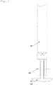
- Figure 2 shows a detailed view of the strut 4, as it is bolted via a bolt on the mast bracket 3 and / or on the subframe 2.
- the clevis can be made narrower than that in the Figure 2
- the middle part of the strut 4 can be the part of the strut 4 arranged between the two fork heads.
- the bolt 9 is indicated by a dashed line which essentially corresponds to the longitudinal axis of a bolt of the bolt 9, not shown.
- Figure 3a shows a strut 4 designed according to the prior art, which has a round cross section and thus has a low level of security against rotation of fastening clamps 5 attached to it.
- the mounting clamps 5 of the Figures 3b - 3e can have a geometry corresponding to the strut 4 at least in sections on their inner sides.
- the fastening clamps 5 can rest at least in sections on the strut.
- the fastening clamps 5 can further comprise one or more flange sections on their outer sides, by means of which the fastening clamps 5 can be fixed to the strut, for example using screws.
- Figure 3c shows the strut 4 of a truck-mounted concrete pump 1 according to the invention, to which an attachment 6 is coupled via a fastening clamp 5.
- the attachment 6 can be coupled with one of its flat outer walls to a flat outer wall of the strut 4 and can thereby be secured against rotation.
- screws 8 are coupled via a clamping part 7 to an attachment part 6, the strut 4 being encompassed by the screws 8 and the clamping part 7.
- the embodiment of the Figure 3e shows an embodiment in which the strut has 4 bushings for receiving screws 8.
- An attachment 6 can in particular be placed on a flat wall of the strut 4 via one of its flat outer walls and screwed to the strut 4 by means of the screws 8 mentioned.
- bushings for receiving the screws 8 can be provided in the strut 4.
- the strut 4 has any angular geometry. However, it is preferably rectangular and in particular square in cross section.
- the strut 4 can have said non-rotatable fork head on at least one of its ends, so that the orientation of the strut cannot change unintentionally. Due to the rectangular cross-section of the strut, it is easily possible to attach brackets for additional parts or attachments to one of them, even with a screw clamp to fix individual strut 4 without the risk of twisting the terminals 5. In addition to their supporting role, struts 4 designed in this way can thus be used as equipment carriers, which saves costs and weight by eliminating other attachment options. Examples of parts to be attached to the strut 4 are, for example, lubrication containers, mast racks, protective covers, oil coolers, hydraulic pipe holders or the like.
Landscapes
- Engineering & Computer Science (AREA)
- Architecture (AREA)
- Mechanical Engineering (AREA)
- Civil Engineering (AREA)
- Structural Engineering (AREA)
- On-Site Construction Work That Accompanies The Preparation And Application Of Concrete (AREA)
Abstract
Description
- Die Erfindung betrifft eine Autobetonpumpe mit einem zum Heck der Autobetonpumpe hin auskragenden Hilfsrahmen und einem Mastbock, wobei der Hilfsrahmen und der Mastbock mittels wenigstens einer Strebe miteinander gekoppelt sind.
- Gattungsgemäße Autobetonpumpen weisen einen zum Maschinenheck hin weit auskragenden Hilfsrahmen auf, der in Verbindung mit dem Lastwagenrahmen als Träger verschiedene Aggregate wie der Pumpe, Wassertanks und/oder anderer Bauteile dient. Um die Lasten dieser Aggregate in die eigentliche Tragstruktur beziehungsweise den Mastbock und den Hilfsrahmen einzuleiten, wählt man üblicherweise fachwerkartige Konstruktionen. Dabei werden der Mastbock und der Hilfsrahmen ganz oder teilweise mittels einer oder mehrerer Streben zu einem biegesteifen Dreieck verbunden. Diese Ausführung ist vergleichsweise einfach und leicht, da sie die freie Biegelänge des Hilfsrahmens stark reduziert. Üblicherweise übernehmen die Streben darüber hinaus keine weitere Funktion.
- Verbauten Streben können bekannterweise beidseitig verbolzt sein. Die gelenkige Anbindung der Streben entlastet die Streben von Biegemomenten, wodurch diese schlanker und dadurch leichter ausgeführt werden können als die sonst üblichen angeschweißten Streben. Dabei ist es bekannt, als Streben ein Rohr bzw. Rundrohr zu verwenden. Rohre weisen aufgrund ihrer Rundheit den Nachteil auf, dass fertigungstechnisch vorteilhafte Schraubklemmen zur Nutzung der Streben als Träger für weitere Bauteile wegen der mit den Rundrohren einhergehenden fehlenden Verdrehsicherung schwierig ausführbar sind. Wenn ein Rundrohr Verwendung findet, so besteht die einzige Möglichkeit zum Anbringen von weiteren Teilen daher in einer Verbindung beider Streben.
- Vor diesem Hintergrund ist es Aufgabe der Erfindung eine verbesserte Autobetonpumpe bereitzustellen, bei der die Streben zum Verbinden des Mastbocks mit dem Hilfsrahmen einfacher als Halter für weitere Komponenten genutzt werden können.
- Diese Aufgabe wird erfindungsgemäß von einer Autobetonpumpe mit den Merkmalen des Anspruchs 1 gelöst. Vorteilhafte Ausbildungen sind Gegenstand der Unteransprüche.
- Demnach ist eine Autobetonpumpe mit einem zum Heck der Autobetonpumpe hin auskragenden Hilfsrahmen und einem Mastbock vorgesehen, wobei der Hilfsrahmen und der Mastbock mittels wenigstens einer Strebe miteinander gekoppelt sind. Die Strebe weist erfindungsgemäß einen eckigen Querschnitt auf. Durch die eckig ausgebildete Außenseite der Strebe ist es möglich an der Strebe Objekte einfacher verdrehsicher zu montieren.
- In einer bevorzugten Ausführung der Erfindung ist denkbar, dass wenigstens zwei insbesondere beidseitig gebolzte Streben vorgesehen sind. Die zwei oder mehr Streben können beispielsweise links und rechts an der Autobetonpumpe angeordnet sein. Die Streben können über Bolzen mit entsprechenden Lagerabschnitten des Mastbocks und des Hilfsrahmens gekoppelt sein.
- In einer weiteren bevorzugten Ausführung der Erfindung ist denkbar, dass die Strebe an wenigstens einem Ende einen verdrehsicheren Gabelkopf umfasst. Der Gabelkopf kann wenigstens teilweise in einem Mittelteil der Strebe fixiert sein.
- In einer weiteren bevorzugten Ausführung der Erfindung ist denkbar, dass die Strebe diagonal von hinten unten nach vorne oben an der Autobetonpumpe verläuft.
- In einer weiteren bevorzugten Ausführung der Erfindung ist denkbar, dass die Strebe wenigstens eine Durchführung zum Aufnehmen von Schrauben umfasst. Die Durchführung kann beispielsweise senkrecht zur Längsausrichtung der Strebe orientiert sein.
- In einer weiteren bevorzugten Ausführung ist denkbar, dass der Gabelkopf schmaler ausgeführt ist als ein Mittelteil der Strebe. Der Mittelteil der Strebe kann denjenigen Abschnitt beschreiben, der sich zwischen zwei einander gegenüberliegend angeordneten Gabelköpfen befindet. Der Mittelteil kann insbesondere durchgängig als Hohlprofilelement ausgebildet sein. Der Gabelkopf kann insgesamt oder Abschnittsweise schmaler als der Mitteilteil ausgebildet sein.
- In einer weiteren bevorzugten Ausführung ist denkbar, dass an der Strebe wenigstens eine Befestigungsschelle vorgesehen ist. Mittels der Befestigungsschelle ist es möglich weitere Komponenten mit der Strebe zu koppeln. Aufgrund des eckigen Querschnitts der Strebe können die Befestigungsschelle und damit das über sie mit der Strebe gekoppelte Objekt nicht ohne weiteres ungewollt um die Strebe rotieren.
- In einer weiteren bevorzugten Ausführung ist denkbar, dass die Strebe mit quadratischem Querschnitt ausgeführt ist. Darüber hinaus kann die Strebe beliebige eckige Querschnitte wie beispielsweise einen allgemein rechteckigen Querschnitt oder einen komplexen Profilquerschnitt mit einem oder mehreren Hohlabschnitten und gegebenenfalls mit damit zusammenhängenden planar bzw. nicht hohl ausgebildeten Abschnitten umfassen.
- Weitere Einzelheiten und Vorteile der Erfindung sind anhand der in den Figuren beispielhaft gezeigten Ausführungen erläutert. Dabei zeigen:
- Figur 1:
- eine schematische Darstellung einer erfindungsgemäßen Autobetonpumpe;
- Figur 2:
- eine schematische Längsansicht einer Strebe; und
- Figuren 3a-e:
- Querschnittsansichten einer Strebe.
-
Figur 1 zeigt eine schematische Ansicht der erfindungsgemäßen Autobetonpumpe 1 mit einem zum Heck der Autobetonpumpe hin auskragendem Hilfsrahmen 2 und einem Mastbock 3. Der Hilfsrahmen 2 und der Mastbock 3 sind mittels wenigstens einer Strebe 4 miteinander gekoppelt. Die Strebe 4 kann einen eckigen und insbesondere rechteckigen Querschnitt aufweisen. - Der Hilfsrahmen 2 kann auf einem Fahrzeugrahmen 11 montiert bzw. mit einem solchen Fahrzeugrahmen 11 gekoppelt sein. Der Fahrzeugrahmen 11 und der Hilfsrahmen 2 können sich in etwa gleich weit in Längsrichtung der Autobetonpumpe 1 erstrecken.
- Im hinteren Bereich des Hilfsrahmens 2 kann ein Trichter 12 vorgesehen sein, der zum Einleiten von Beton in die Autobetonpumpe 1 dient.
- Die in
Figur 1 gezeigte Strebe 4 kann beidseitig über Bolzen beziehungsweise über eine Verbolzung 9 mit dem Hilfsrahmen 2 und dem Mastbock 3 gekoppelt sein. Eine der Verbolzungen 9 kann im Bereich einer Mastauflage 10 angeordnet sein, die zum Auflegen eines nicht gezeigten Mastes der Autobetonpumpe 1 eingerichtet ist. Diese Verbolzung 9 kann insbesondere in einem Bereich der Mastauflage 10 verortet sein, der dem Hilfsrahmen 2 direkt benachbart ist bzw. der derjenige Bereich der Mastauflage 10 ist, der dem Hilfsrahmen 2 am nächsten ist. - Die Strebe 4 kann an wenigstens einem ihrer Enden einen verdrehsicheren Gabelkopf umfassen, über den die Strebe 4 verbolzbar ist.
- Die in
Figur 1 gezeigte Strebe 4 ist an der Autobetonpumpe 1 von hinten unten nach vorne oben geführt. Denkbar ist auch, dass die Strebe 4 dabei von außen nach innen oder von innen nach außen an der Autobetonpumpe 1 verläuft. -
Figur 2 zeigt eine Detailansicht der Strebe 4, wie sie über eine Verbolzung am Mastbock 3 und/oder am Hilfsrahmen 2 verbolzt ist. Der Gabelkopf kann schmaler ausgeführt sein, als der in derFigur 2 rechts gezeigte Mittelteil der Strebe 4. Der Mittelteil der Strebe 4 kann das zwischen den beiden Gabelköpfen angeordnete Teil der Strebe 4 sein. - Die Verbolzung 9 ist durch eine gestrichelte Linie angezeigt, die im Wesentlichen der Längsachse eines nicht gezeigten Bolzens der Verbolzung 9 entspricht.
- Die durchgestrichenen Pfeile in
Figur 2 sowie in enFiguren 3b -3e zeigen an, dass durch die eckige Querschnittsgeometrie der Strebe 4 eine Verdrehsicherung von an der Strebe 4 befestigten Komponenten gegeben ist.Figur 3a zeigt dagegen eine Strebe 4 mit einem aus dem Stand der Technik bekannten runden Querschnitt, bei der eine solche Verdrehsicherung nicht gegeben ist. -
Figur 3a zeigt eine gemäß dem Stand der Technik ausgeführte Strebe 4, die einen runden Querschnitt aufweist und damit eine geringe Sicherung gegen Verdrehen von daran befestigten Befestigungsschellen 5 aufweist. - Im Gegensatz dazu zeigt die in
Figur 3b gezeigte Ausführung den Querschnitt einer Strebe 4, der eckig ausgeführt ist, und an dem entsprechend eckig beziehungsweise gekantet ausgeführte Befestigungsschellen 5 gegen ein Verdrehen relativ zur Strebe 4 gesichert sind. - Die Befestigungsschellen 5 der
Figuren 3b - 3e können an ihren Innenseiten wenigstens abschnittsweise eine der Strebe 4 entsprechende Geometrie aufweisen. Insbesondere können die Befestigungsschellen 5 wenigstens abschnittsweise an der Strebe anliegen. - Die Befestigungsschellen 5 können ferner an ihren Außenseiten einen oder mehrere Flanschabschnitte umfassen, mittels der die Befestigungsschellen 5 beispielsweise unter Verwendung von Schrauben an der Strebe fixierbar sind.
-
Figur 3c zeigt die Strebe 4 einer erfindungsgemäßen Autobetonpumpe 1, an der ein Anbauteil 6 über eine Befestigungsschelle 5 gekoppelt ist. Das Anbauteil 6 kann mit einer seiner flachen Außenwände an eine flache Außenwand der Strebe 4 gekoppelt sein und hierdurch eine Verdrehsicherung erfahren. - In dem Ausführungsbeispiel der
Figur 3d sind Schrauben 8 über ein Klemmteil 7 mit einem Anbauteil 6 gekoppelt, wobei die Strebe 4 von den Schrauben 8 und dem Klemmteil 7 umgriffen ist. - Das Ausführungsbeispiel der
Figur 3e zeigt eine Ausführung bei der die Strebe 4 Durchführungen zum Aufnehmen von Schrauben 8 aufweist. Ein Anbauteil 6 kann insbesondere über eine von dessen flachen Außenwänden an eine flache Wandung der Strebe 4 angelegt werden und über die genannten Schrauben 8 mit der Strebe 4 verschraubt werden. Hierzu können in der Strebe 4 Durchführungen zum Aufnehmen der Schrauben 8 vorgesehen sein. - Die Strebe 4 weist eine beliebige eckige Geometrie auf. Bevorzugt ist sie jedoch rechteckig und insbesondere quadratischen Querschnitts.
- Die Strebe 4 kann an wenigstens einem ihrer Enden den genannten verdrehsicheren Gabelkopf aufweisen, damit sich die Ausrichtung der Strebe nicht ungewollt ändern kann. Durch den Rechteckquerschnitt der Strebe ist es einfach möglich, Halter für weitere Teile oder Anbauteile selbst per Schraubklemmung auch an einer einzelnen Strebe 4 zu befestigen, ohne dass die Gefahr einer Verdrehung der Klemmen 5 besteht. Neben ihrer tragenden Rolle können so ausgeführte Streben 4 damit als Geräteträger verwendet werden, was Kosten und Gewicht durch Entfall sonstiger Anbringmöglichkeiten spart. Beispiele für an der Strebe 4 anzubringende Teile sind etwa Schmierbehälter, Mastablagen, Schutzabdeckungen, Ölkühler, Hydraulikrohrhalter oder ähnliches.
Claims (8)
- Autobetonpumpe (1) mit einem zum Heck der Autobetonpumpe (1) hin auskragenden Hilfsrahmen (2) und einem Mastbock (3), wobei der Hilfsrahmen (2) und der Mastbock (3) mittels wenigstens einer Strebe (4) miteinander gekoppelt sind, dadurch gekennzeichnet, dass die Strebe (4) einen eckigen Querschnitt aufweist.
- Autobetonpumpe (1) nach Anspruch 1, dadurch gekennzeichnet, dass wenigstens zwei insbesondere beidseitig gebolzte Streben (4) vorgesehen sind.
- Autobetonpumpe (1) nach Anspruch 1 oder 2, dadurch gekennzeichnet, dass die Strebe (4) an wenigstens einem Ende einen verdrehsicheren Gabelkopf umfasst.
- Autobetonpumpe (1) nach einem der vorhergehenden Ansprüche, dadurch gekennzeichnet, dass die Strebe (4) diagonal von hinten unten nach vorne oben an der Autobetonpumpe (1) verläuft.
- Autobetonpumpe (1) nach einem der vorhergehenden Ansprüche, dadurch gekennzeichnet, dass die Strebe (4) wenigstens eine Durchführung zum Aufnehmen von Schrauben umfasst.
- Autobetonpumpe (1) nach wenigstens nach Anspruch 3, dadurch gekennzeichnet, dass der Gabelkopf schmaler ausgeführt ist als ein Mittelteil der Strebe (4).
- Autobetonpumpe (1) nach einem der vorhergehenden Ansprüche, dadurch gekennzeichnet, dass an der Strebe (4) wenigstens eine Befestigungsschelle (5) vorgesehen ist.
- Autobetonpumpe (1) nach einem der vorhergehenden Ansprüche, dadurch gekennzeichnet, dass die Strebe (4) mit quadratischem Querschnitt ausgeführt ist.
Applications Claiming Priority (1)
| Application Number | Priority Date | Filing Date | Title |
|---|---|---|---|
| DE102018129799.8A DE102018129799A1 (de) | 2018-11-26 | 2018-11-26 | Autobetonpumpe |
Publications (2)
| Publication Number | Publication Date |
|---|---|
| EP3656947A1 true EP3656947A1 (de) | 2020-05-27 |
| EP3656947B1 EP3656947B1 (de) | 2023-01-04 |
Family
ID=68470362
Family Applications (1)
| Application Number | Title | Priority Date | Filing Date |
|---|---|---|---|
| EP19207419.3A Active EP3656947B1 (de) | 2018-11-26 | 2019-11-06 | Autobetonpumpe |
Country Status (3)
| Country | Link |
|---|---|
| EP (1) | EP3656947B1 (de) |
| DE (1) | DE102018129799A1 (de) |
| ES (1) | ES2941917T3 (de) |
Cited By (2)
| Publication number | Priority date | Publication date | Assignee | Title |
|---|---|---|---|---|
| WO2022128326A1 (de) * | 2020-12-17 | 2022-06-23 | Putzmeister Engineering Gmbh | Rahmengestell mit einem mastbock zur lagerung eines dickstoffverteilermasts |
| EP4092221A1 (de) * | 2021-05-19 | 2022-11-23 | Liebherr-Mischtechnik GmbH | Autobetonpumpe mit vorgespannter zugstrebe |
Citations (2)
| Publication number | Priority date | Publication date | Assignee | Title |
|---|---|---|---|---|
| CN201424817Y (zh) * | 2009-04-24 | 2010-03-17 | 徐州重型机械有限公司 | 混凝土泵车的上下车连接装置及具有该装置的混凝土泵车 |
| CN105275210A (zh) * | 2014-07-24 | 2016-01-27 | 中联重科股份有限公司 | 一种泵车承载结构及混凝土泵车 |
Family Cites Families (5)
| Publication number | Priority date | Publication date | Assignee | Title |
|---|---|---|---|---|
| WO2003098090A1 (de) | 2002-05-17 | 2003-11-27 | Aba Of Sweden Ab | Rohrschelle |
| DE102010009177A1 (de) * | 2010-02-24 | 2011-08-25 | Elba-Werk Maschinen-Gesellschaft mbH, 76275 | Mast, insbesondere Arbeitsmast für Autobetonpumpen, sowie Autobetonpumpe mit einem solchen Mast |
| US8336837B2 (en) | 2010-12-01 | 2012-12-25 | Gephart Joel A | Universal clamp assembly |
| DE102012213727A1 (de) * | 2012-08-02 | 2014-02-06 | Putzmeister Engineering Gmbh | Betonverteilermast für Betonpumpen |
| DE102014208472A1 (de) * | 2014-05-06 | 2015-11-12 | Putzmeister Engineering Gmbh | Autobetonpumpe |
-
2018
- 2018-11-26 DE DE102018129799.8A patent/DE102018129799A1/de active Pending
-
2019
- 2019-11-06 EP EP19207419.3A patent/EP3656947B1/de active Active
- 2019-11-06 ES ES19207419T patent/ES2941917T3/es active Active
Patent Citations (2)
| Publication number | Priority date | Publication date | Assignee | Title |
|---|---|---|---|---|
| CN201424817Y (zh) * | 2009-04-24 | 2010-03-17 | 徐州重型机械有限公司 | 混凝土泵车的上下车连接装置及具有该装置的混凝土泵车 |
| CN105275210A (zh) * | 2014-07-24 | 2016-01-27 | 中联重科股份有限公司 | 一种泵车承载结构及混凝土泵车 |
Cited By (3)
| Publication number | Priority date | Publication date | Assignee | Title |
|---|---|---|---|---|
| WO2022128326A1 (de) * | 2020-12-17 | 2022-06-23 | Putzmeister Engineering Gmbh | Rahmengestell mit einem mastbock zur lagerung eines dickstoffverteilermasts |
| US12416169B2 (en) | 2020-12-17 | 2025-09-16 | Putzmeister Engineering Gmbh | Frame with a boom pedestal for mounting a thick matter distribution boom |
| EP4092221A1 (de) * | 2021-05-19 | 2022-11-23 | Liebherr-Mischtechnik GmbH | Autobetonpumpe mit vorgespannter zugstrebe |
Also Published As
| Publication number | Publication date |
|---|---|
| ES2941917T3 (es) | 2023-05-26 |
| DE102018129799A1 (de) | 2020-05-28 |
| EP3656947B1 (de) | 2023-01-04 |
Similar Documents
| Publication | Publication Date | Title |
|---|---|---|
| DE2107477C3 (de) | Markisenkasten für eine Gelenkarmmarkise | |
| DE10321493B4 (de) | Klappspitzen-Abwinklungsvorrichtung | |
| EP2822831B1 (de) | Strukturstabile anordnung und verfahren zur bildung einer strukturstabilen anordnung | |
| EP3656947B1 (de) | Autobetonpumpe | |
| EP2214534A1 (de) | Verfahren zur reparatur einer stütze oder einer strebe eines regals und reparatur- und verstärkungssets dazu | |
| DE102010007995A1 (de) | Fahrzeugkarosserieaufbau im Bereich zwischen Federbeinaufnahmen und Scheibenquerträger sowie zugeordnetes Fertigungsverfahren | |
| EP2420406B1 (de) | Vorrichtung zum Sichern von Ladung auf einer Ladefläche eines Fahrzeugaufbaus | |
| EP3157720B1 (de) | Fahrmischerpumpe | |
| EP3319898B1 (de) | Turmkran | |
| DE102011119656B4 (de) | Fahrzeugkran | |
| EP3157721B1 (de) | Fahrmischerpumpe mit abstützeinrichtung | |
| WO2014044395A1 (de) | Umfassungsrahmen, verfahren zum montieren eines umfassungsrahmens, und|verwendung eines umfassungsrahmens zum verbinden eines turmdrehkrans mit einem objekt | |
| DE202011005128U1 (de) | Kippvorrichtung für Hubwagen | |
| DE102007035655B4 (de) | Abstützvorrichtung für Außenbordmotor | |
| DE3151556A1 (de) | Vorrichtung mit wenigstens zwei aggregaten | |
| DE102012110685A1 (de) | Fensterrahmenstütze | |
| EP1065093A1 (de) | Schwenkausleger für Oberleitungsanlagen | |
| DE10231625A1 (de) | Hebevorrichtung | |
| EP0805069A1 (de) | Befestigungsvorrichtung für eine Hubladebühne | |
| EP1889742A2 (de) | Element zur Befestigung des Tanks an der Karosserie eines Kraftfahrzeuges | |
| DE202017101211U1 (de) | Ladekran zur Montage auf einem Fahrzeug | |
| EP4092221A1 (de) | Autobetonpumpe mit vorgespannter zugstrebe | |
| CH664332A5 (en) | Wall bracket for storing bicycle - has hinged support arm with sprung mounting and with grips to hold bicycle frame | |
| DE202017104892U1 (de) | Aufbau-Adapter für Fahrrad-Heckträger, und Aufbau-Anordnung | |
| EP3836323A1 (de) | Ausleger und montagevorrichtung mit einem ausleger |
Legal Events
| Date | Code | Title | Description |
|---|---|---|---|
| PUAI | Public reference made under article 153(3) epc to a published international application that has entered the european phase |
Free format text: ORIGINAL CODE: 0009012 |
|
| STAA | Information on the status of an ep patent application or granted ep patent |
Free format text: STATUS: THE APPLICATION HAS BEEN PUBLISHED |
|
| AK | Designated contracting states |
Kind code of ref document: A1 Designated state(s): AL AT BE BG CH CY CZ DE DK EE ES FI FR GB GR HR HU IE IS IT LI LT LU LV MC MK MT NL NO PL PT RO RS SE SI SK SM TR |
|
| AX | Request for extension of the european patent |
Extension state: BA ME |
|
| RAP1 | Party data changed (applicant data changed or rights of an application transferred) |
Owner name: LIEBHERR-MISCHTECHNIK GMBH |
|
| STAA | Information on the status of an ep patent application or granted ep patent |
Free format text: STATUS: REQUEST FOR EXAMINATION WAS MADE |
|
| 17P | Request for examination filed |
Effective date: 20201123 |
|
| GRAP | Despatch of communication of intention to grant a patent |
Free format text: ORIGINAL CODE: EPIDOSNIGR1 |
|
| STAA | Information on the status of an ep patent application or granted ep patent |
Free format text: STATUS: GRANT OF PATENT IS INTENDED |
|
| INTG | Intention to grant announced |
Effective date: 20221005 |
|
| GRAS | Grant fee paid |
Free format text: ORIGINAL CODE: EPIDOSNIGR3 |
|
| GRAA | (expected) grant |
Free format text: ORIGINAL CODE: 0009210 |
|
| STAA | Information on the status of an ep patent application or granted ep patent |
Free format text: STATUS: THE PATENT HAS BEEN GRANTED |
|
| AK | Designated contracting states |
Kind code of ref document: B1 Designated state(s): AL AT BE BG CH CY CZ DE DK EE ES FI FR GB GR HR HU IE IS IT LI LT LU LV MC MK MT NL NO PL PT RO RS SE SI SK SM TR |
|
| REG | Reference to a national code |
Ref country code: GB Ref legal event code: FG4D Free format text: NOT ENGLISH |
|
| REG | Reference to a national code |
Ref country code: CH Ref legal event code: EP |
|
| REG | Reference to a national code |
Ref country code: AT Ref legal event code: REF Ref document number: 1542019 Country of ref document: AT Kind code of ref document: T Effective date: 20230115 |
|
| REG | Reference to a national code |
Ref country code: DE Ref legal event code: R096 Ref document number: 502019006681 Country of ref document: DE |
|
| REG | Reference to a national code |
Ref country code: IE Ref legal event code: FG4D Free format text: LANGUAGE OF EP DOCUMENT: GERMAN |
|
| REG | Reference to a national code |
Ref country code: LT Ref legal event code: MG9D |
|
| REG | Reference to a national code |
Ref country code: NL Ref legal event code: MP Effective date: 20230104 |
|
| REG | Reference to a national code |
Ref country code: ES Ref legal event code: FG2A Ref document number: 2941917 Country of ref document: ES Kind code of ref document: T3 Effective date: 20230526 |
|
| PG25 | Lapsed in a contracting state [announced via postgrant information from national office to epo] |
Ref country code: NL Free format text: LAPSE BECAUSE OF FAILURE TO SUBMIT A TRANSLATION OF THE DESCRIPTION OR TO PAY THE FEE WITHIN THE PRESCRIBED TIME-LIMIT Effective date: 20230104 |
|
| PG25 | Lapsed in a contracting state [announced via postgrant information from national office to epo] |
Ref country code: RS Free format text: LAPSE BECAUSE OF FAILURE TO SUBMIT A TRANSLATION OF THE DESCRIPTION OR TO PAY THE FEE WITHIN THE PRESCRIBED TIME-LIMIT Effective date: 20230104 Ref country code: PT Free format text: LAPSE BECAUSE OF FAILURE TO SUBMIT A TRANSLATION OF THE DESCRIPTION OR TO PAY THE FEE WITHIN THE PRESCRIBED TIME-LIMIT Effective date: 20230504 Ref country code: NO Free format text: LAPSE BECAUSE OF FAILURE TO SUBMIT A TRANSLATION OF THE DESCRIPTION OR TO PAY THE FEE WITHIN THE PRESCRIBED TIME-LIMIT Effective date: 20230404 Ref country code: LV Free format text: LAPSE BECAUSE OF FAILURE TO SUBMIT A TRANSLATION OF THE DESCRIPTION OR TO PAY THE FEE WITHIN THE PRESCRIBED TIME-LIMIT Effective date: 20230104 Ref country code: LT Free format text: LAPSE BECAUSE OF FAILURE TO SUBMIT A TRANSLATION OF THE DESCRIPTION OR TO PAY THE FEE WITHIN THE PRESCRIBED TIME-LIMIT Effective date: 20230104 Ref country code: HR Free format text: LAPSE BECAUSE OF FAILURE TO SUBMIT A TRANSLATION OF THE DESCRIPTION OR TO PAY THE FEE WITHIN THE PRESCRIBED TIME-LIMIT Effective date: 20230104 |
|
| PG25 | Lapsed in a contracting state [announced via postgrant information from national office to epo] |
Ref country code: SE Free format text: LAPSE BECAUSE OF FAILURE TO SUBMIT A TRANSLATION OF THE DESCRIPTION OR TO PAY THE FEE WITHIN THE PRESCRIBED TIME-LIMIT Effective date: 20230104 Ref country code: PL Free format text: LAPSE BECAUSE OF FAILURE TO SUBMIT A TRANSLATION OF THE DESCRIPTION OR TO PAY THE FEE WITHIN THE PRESCRIBED TIME-LIMIT Effective date: 20230104 Ref country code: IS Free format text: LAPSE BECAUSE OF FAILURE TO SUBMIT A TRANSLATION OF THE DESCRIPTION OR TO PAY THE FEE WITHIN THE PRESCRIBED TIME-LIMIT Effective date: 20230504 Ref country code: GR Free format text: LAPSE BECAUSE OF FAILURE TO SUBMIT A TRANSLATION OF THE DESCRIPTION OR TO PAY THE FEE WITHIN THE PRESCRIBED TIME-LIMIT Effective date: 20230405 Ref country code: FI Free format text: LAPSE BECAUSE OF FAILURE TO SUBMIT A TRANSLATION OF THE DESCRIPTION OR TO PAY THE FEE WITHIN THE PRESCRIBED TIME-LIMIT Effective date: 20230104 |
|
| REG | Reference to a national code |
Ref country code: DE Ref legal event code: R026 Ref document number: 502019006681 Country of ref document: DE |
|
| PLBI | Opposition filed |
Free format text: ORIGINAL CODE: 0009260 |
|
| PLAX | Notice of opposition and request to file observation + time limit sent |
Free format text: ORIGINAL CODE: EPIDOSNOBS2 |
|
| PG25 | Lapsed in a contracting state [announced via postgrant information from national office to epo] |
Ref country code: SM Free format text: LAPSE BECAUSE OF FAILURE TO SUBMIT A TRANSLATION OF THE DESCRIPTION OR TO PAY THE FEE WITHIN THE PRESCRIBED TIME-LIMIT Effective date: 20230104 Ref country code: RO Free format text: LAPSE BECAUSE OF FAILURE TO SUBMIT A TRANSLATION OF THE DESCRIPTION OR TO PAY THE FEE WITHIN THE PRESCRIBED TIME-LIMIT Effective date: 20230104 Ref country code: EE Free format text: LAPSE BECAUSE OF FAILURE TO SUBMIT A TRANSLATION OF THE DESCRIPTION OR TO PAY THE FEE WITHIN THE PRESCRIBED TIME-LIMIT Effective date: 20230104 Ref country code: DK Free format text: LAPSE BECAUSE OF FAILURE TO SUBMIT A TRANSLATION OF THE DESCRIPTION OR TO PAY THE FEE WITHIN THE PRESCRIBED TIME-LIMIT Effective date: 20230104 Ref country code: CZ Free format text: LAPSE BECAUSE OF FAILURE TO SUBMIT A TRANSLATION OF THE DESCRIPTION OR TO PAY THE FEE WITHIN THE PRESCRIBED TIME-LIMIT Effective date: 20230104 |
|
| 26 | Opposition filed |
Opponent name: PUTZMEISTER ENGINEERING GMBH Effective date: 20231004 |
|
| PG25 | Lapsed in a contracting state [announced via postgrant information from national office to epo] |
Ref country code: SK Free format text: LAPSE BECAUSE OF FAILURE TO SUBMIT A TRANSLATION OF THE DESCRIPTION OR TO PAY THE FEE WITHIN THE PRESCRIBED TIME-LIMIT Effective date: 20230104 |
|
| PGFP | Annual fee paid to national office [announced via postgrant information from national office to epo] |
Ref country code: ES Payment date: 20231201 Year of fee payment: 5 |
|
| PG25 | Lapsed in a contracting state [announced via postgrant information from national office to epo] |
Ref country code: SI Free format text: LAPSE BECAUSE OF FAILURE TO SUBMIT A TRANSLATION OF THE DESCRIPTION OR TO PAY THE FEE WITHIN THE PRESCRIBED TIME-LIMIT Effective date: 20230104 |
|
| PGFP | Annual fee paid to national office [announced via postgrant information from national office to epo] |
Ref country code: TR Payment date: 20231026 Year of fee payment: 5 |
|
| PLBB | Reply of patent proprietor to notice(s) of opposition received |
Free format text: ORIGINAL CODE: EPIDOSNOBS3 |
|
| PLAY | Examination report in opposition despatched + time limit |
Free format text: ORIGINAL CODE: EPIDOSNORE2 |
|
| PG25 | Lapsed in a contracting state [announced via postgrant information from national office to epo] |
Ref country code: MC Free format text: LAPSE BECAUSE OF FAILURE TO SUBMIT A TRANSLATION OF THE DESCRIPTION OR TO PAY THE FEE WITHIN THE PRESCRIBED TIME-LIMIT Effective date: 20230104 |
|
| PG25 | Lapsed in a contracting state [announced via postgrant information from national office to epo] |
Ref country code: LU Free format text: LAPSE BECAUSE OF NON-PAYMENT OF DUE FEES Effective date: 20231106 |
|
| GBPC | Gb: european patent ceased through non-payment of renewal fee |
Effective date: 20231106 |
|
| PG25 | Lapsed in a contracting state [announced via postgrant information from national office to epo] |
Ref country code: MC Free format text: LAPSE BECAUSE OF FAILURE TO SUBMIT A TRANSLATION OF THE DESCRIPTION OR TO PAY THE FEE WITHIN THE PRESCRIBED TIME-LIMIT Effective date: 20230104 Ref country code: LU Free format text: LAPSE BECAUSE OF NON-PAYMENT OF DUE FEES Effective date: 20231106 |
|
| REG | Reference to a national code |
Ref country code: BE Ref legal event code: MM Effective date: 20231130 |
|
| PLBC | Reply to examination report in opposition received |
Free format text: ORIGINAL CODE: EPIDOSNORE3 |
|
| REG | Reference to a national code |
Ref country code: IE Ref legal event code: MM4A |
|
| PG25 | Lapsed in a contracting state [announced via postgrant information from national office to epo] |
Ref country code: IE Free format text: LAPSE BECAUSE OF NON-PAYMENT OF DUE FEES Effective date: 20231106 |
|
| PG25 | Lapsed in a contracting state [announced via postgrant information from national office to epo] |
Ref country code: GB Free format text: LAPSE BECAUSE OF NON-PAYMENT OF DUE FEES Effective date: 20231106 |
|
| PG25 | Lapsed in a contracting state [announced via postgrant information from national office to epo] |
Ref country code: BE Free format text: LAPSE BECAUSE OF NON-PAYMENT OF DUE FEES Effective date: 20231130 |
|
| PG25 | Lapsed in a contracting state [announced via postgrant information from national office to epo] |
Ref country code: IE Free format text: LAPSE BECAUSE OF NON-PAYMENT OF DUE FEES Effective date: 20231106 Ref country code: GB Free format text: LAPSE BECAUSE OF NON-PAYMENT OF DUE FEES Effective date: 20231106 Ref country code: BE Free format text: LAPSE BECAUSE OF NON-PAYMENT OF DUE FEES Effective date: 20231130 |
|
| PG25 | Lapsed in a contracting state [announced via postgrant information from national office to epo] |
Ref country code: BG Free format text: LAPSE BECAUSE OF FAILURE TO SUBMIT A TRANSLATION OF THE DESCRIPTION OR TO PAY THE FEE WITHIN THE PRESCRIBED TIME-LIMIT Effective date: 20230104 |
|
| PG25 | Lapsed in a contracting state [announced via postgrant information from national office to epo] |
Ref country code: BG Free format text: LAPSE BECAUSE OF FAILURE TO SUBMIT A TRANSLATION OF THE DESCRIPTION OR TO PAY THE FEE WITHIN THE PRESCRIBED TIME-LIMIT Effective date: 20230104 |
|
| PLAB | Opposition data, opponent's data or that of the opponent's representative modified |
Free format text: ORIGINAL CODE: 0009299OPPO |
|
| R26 | Opposition filed (corrected) |
Opponent name: PUTZMEISTER ENGINEERING GMBH Effective date: 20231004 |
|
| PG25 | Lapsed in a contracting state [announced via postgrant information from national office to epo] |
Ref country code: CY Free format text: LAPSE BECAUSE OF FAILURE TO SUBMIT A TRANSLATION OF THE DESCRIPTION OR TO PAY THE FEE WITHIN THE PRESCRIBED TIME-LIMIT; INVALID AB INITIO Effective date: 20191106 |
|
| PG25 | Lapsed in a contracting state [announced via postgrant information from national office to epo] |
Ref country code: HU Free format text: LAPSE BECAUSE OF FAILURE TO SUBMIT A TRANSLATION OF THE DESCRIPTION OR TO PAY THE FEE WITHIN THE PRESCRIBED TIME-LIMIT; INVALID AB INITIO Effective date: 20191106 |
|
| REG | Reference to a national code |
Ref country code: CH Ref legal event code: U11 Free format text: ST27 STATUS EVENT CODE: U-0-0-U10-U11 (AS PROVIDED BY THE NATIONAL OFFICE) Effective date: 20251201 |
|
| REG | Reference to a national code |
Ref country code: ES Ref legal event code: FD2A Effective date: 20251230 |
|
| PGFP | Annual fee paid to national office [announced via postgrant information from national office to epo] |
Ref country code: DE Payment date: 20251201 Year of fee payment: 7 |
|
| PGFP | Annual fee paid to national office [announced via postgrant information from national office to epo] |
Ref country code: AT Payment date: 20251124 Year of fee payment: 7 |
|
| PGFP | Annual fee paid to national office [announced via postgrant information from national office to epo] |
Ref country code: IT Payment date: 20251127 Year of fee payment: 7 |
|
| PGFP | Annual fee paid to national office [announced via postgrant information from national office to epo] |
Ref country code: FR Payment date: 20251128 Year of fee payment: 7 |
|
| PGFP | Annual fee paid to national office [announced via postgrant information from national office to epo] |
Ref country code: CH Payment date: 20251201 Year of fee payment: 7 |
|
| PG25 | Lapsed in a contracting state [announced via postgrant information from national office to epo] |
Ref country code: ES Free format text: LAPSE BECAUSE OF NON-PAYMENT OF DUE FEES Effective date: 20241107 |