EP3657210B1 - Navigationsverfahren und -system eines luftfahrzeugs - Google Patents
Navigationsverfahren und -system eines luftfahrzeugs Download PDFInfo
- Publication number
- EP3657210B1 EP3657210B1 EP19208550.4A EP19208550A EP3657210B1 EP 3657210 B1 EP3657210 B1 EP 3657210B1 EP 19208550 A EP19208550 A EP 19208550A EP 3657210 B1 EP3657210 B1 EP 3657210B1
- Authority
- EP
- European Patent Office
- Prior art keywords
- aircraft
- radio
- tuple
- radio beacons
- beacons
- Prior art date
- Legal status (The legal status is an assumption and is not a legal conclusion. Google has not performed a legal analysis and makes no representation as to the accuracy of the status listed.)
- Active
Links
Images



Classifications
-
- G—PHYSICS
- G01—MEASURING; TESTING
- G01S—RADIO DIRECTION-FINDING; RADIO NAVIGATION; DETERMINING DISTANCE OR VELOCITY BY USE OF RADIO WAVES; LOCATING OR PRESENCE-DETECTING BY USE OF THE REFLECTION OR RERADIATION OF RADIO WAVES; ANALOGOUS ARRANGEMENTS USING OTHER WAVES
- G01S13/00—Systems using the reflection or reradiation of radio waves, e.g. radar systems; Analogous systems using reflection or reradiation of waves whose nature or wavelength is irrelevant or unspecified
- G01S13/74—Systems using reradiation of radio waves, e.g. secondary radar systems; Analogous systems
- G01S13/76—Systems using reradiation of radio waves, e.g. secondary radar systems; Analogous systems wherein pulse-type signals are transmitted
- G01S13/78—Systems using reradiation of radio waves, e.g. secondary radar systems; Analogous systems wherein pulse-type signals are transmitted discriminating between different kinds of targets, e.g. IFF-radar, i.e. identification of friend or foe
- G01S13/785—Distance Measuring Equipment [DME] systems
-
- G—PHYSICS
- G01—MEASURING; TESTING
- G01C—MEASURING DISTANCES, LEVELS OR BEARINGS; SURVEYING; NAVIGATION; GYROSCOPIC INSTRUMENTS; PHOTOGRAMMETRY OR VIDEOGRAMMETRY
- G01C23/00—Combined instruments indicating more than one navigational value, e.g. for aircraft; Combined measuring devices for measuring two or more variables of movement, e.g. distance, speed or acceleration
-
- G—PHYSICS
- G01—MEASURING; TESTING
- G01C—MEASURING DISTANCES, LEVELS OR BEARINGS; SURVEYING; NAVIGATION; GYROSCOPIC INSTRUMENTS; PHOTOGRAMMETRY OR VIDEOGRAMMETRY
- G01C21/00—Navigation; Navigational instruments not provided for in groups G01C1/00 - G01C19/00
- G01C21/005—Navigation; Navigational instruments not provided for in groups G01C1/00 - G01C19/00 with correlation of navigation data from several sources, e.g. map or contour matching
-
- G—PHYSICS
- G01—MEASURING; TESTING
- G01C—MEASURING DISTANCES, LEVELS OR BEARINGS; SURVEYING; NAVIGATION; GYROSCOPIC INSTRUMENTS; PHOTOGRAMMETRY OR VIDEOGRAMMETRY
- G01C21/00—Navigation; Navigational instruments not provided for in groups G01C1/00 - G01C19/00
- G01C21/20—Instruments for performing navigational calculations
-
- G—PHYSICS
- G01—MEASURING; TESTING
- G01S—RADIO DIRECTION-FINDING; RADIO NAVIGATION; DETERMINING DISTANCE OR VELOCITY BY USE OF RADIO WAVES; LOCATING OR PRESENCE-DETECTING BY USE OF THE REFLECTION OR RERADIATION OF RADIO WAVES; ANALOGOUS ARRANGEMENTS USING OTHER WAVES
- G01S1/00—Beacons or beacon systems transmitting signals having a characteristic or characteristics capable of being detected by non-directional receivers and defining directions, positions, or position lines fixed relatively to the beacon transmitters; Receivers co-operating therewith
- G01S1/02—Beacons or beacon systems transmitting signals having a characteristic or characteristics capable of being detected by non-directional receivers and defining directions, positions, or position lines fixed relatively to the beacon transmitters; Receivers co-operating therewith using radio waves
- G01S1/022—Means for monitoring or calibrating
- G01S1/026—Means for monitoring or calibrating of associated receivers
-
- G—PHYSICS
- G01—MEASURING; TESTING
- G01S—RADIO DIRECTION-FINDING; RADIO NAVIGATION; DETERMINING DISTANCE OR VELOCITY BY USE OF RADIO WAVES; LOCATING OR PRESENCE-DETECTING BY USE OF THE REFLECTION OR RERADIATION OF RADIO WAVES; ANALOGOUS ARRANGEMENTS USING OTHER WAVES
- G01S19/00—Satellite radio beacon positioning systems; Determining position, velocity or attitude using signals transmitted by such systems
- G01S19/38—Determining a navigation solution using signals transmitted by a satellite radio beacon positioning system
- G01S19/39—Determining a navigation solution using signals transmitted by a satellite radio beacon positioning system the satellite radio beacon positioning system transmitting time-stamped messages, e.g. GPS [Global Positioning System], GLONASS [Global Orbiting Navigation Satellite System] or GALILEO
- G01S19/42—Determining position
- G01S19/48—Determining position by combining or switching between position solutions derived from the satellite radio beacon positioning system and position solutions derived from a further system
-
- G—PHYSICS
- G01—MEASURING; TESTING
- G01S—RADIO DIRECTION-FINDING; RADIO NAVIGATION; DETERMINING DISTANCE OR VELOCITY BY USE OF RADIO WAVES; LOCATING OR PRESENCE-DETECTING BY USE OF THE REFLECTION OR RERADIATION OF RADIO WAVES; ANALOGOUS ARRANGEMENTS USING OTHER WAVES
- G01S5/00—Position-fixing by co-ordinating two or more direction or position line determinations; Position-fixing by co-ordinating two or more distance determinations
- G01S5/01—Determining conditions which influence positioning, e.g. radio environment, state of motion or energy consumption
- G01S5/011—Identifying the radio environment
-
- G—PHYSICS
- G08—SIGNALLING
- G08C—TRANSMISSION SYSTEMS FOR MEASURED VALUES, CONTROL OR SIMILAR SIGNALS
- G08C17/00—Arrangements for transmitting signals characterised by the use of a wireless electrical link
- G08C17/02—Arrangements for transmitting signals characterised by the use of a wireless electrical link using a radio link
-
- G—PHYSICS
- G01—MEASURING; TESTING
- G01S—RADIO DIRECTION-FINDING; RADIO NAVIGATION; DETERMINING DISTANCE OR VELOCITY BY USE OF RADIO WAVES; LOCATING OR PRESENCE-DETECTING BY USE OF THE REFLECTION OR RERADIATION OF RADIO WAVES; ANALOGOUS ARRANGEMENTS USING OTHER WAVES
- G01S2201/00—Indexing scheme relating to beacons or beacon systems transmitting signals capable of being detected by non-directional receivers and defining directions, positions, or position lines fixed relatively to the beacon transmitters
- G01S2201/01—Indexing scheme relating to beacons or beacon systems transmitting signals capable of being detected by non-directional receivers and defining directions, positions, or position lines fixed relatively to the beacon transmitters adapted for specific applications or environments
- G01S2201/06—Aircraft navigation
Definitions
- the present invention relates to an aircraft navigation method and an associated navigation system.
- the International Civil Aviation Organization which is involved in developing standards for international air transport, has defined performance-based navigation, or PBN.
- PBN navigation consists of determining, from sensors installed on the aircraft, a spatial position of the aircraft and using this position to guide the aircraft along an air route defined by waypoints.
- the air routes usable in civil aviation are defined by the ICAO.
- this type of navigation requires calculating the aircraft's position with an associated uncertainty estimate, called EPU (Estimate of Position Uncertainty).
- the EPU is calculated assuming there is no latent failure that could affect the measurements used for position calculation.
- a positioning accuracy performance level can then be imposed, for example, an accuracy of 95% +/- 10 Nm (nautical miles).
- RNP Required Navigation Performance
- RNP navigation requires two positioning accuracy performance level indicators, a first indicator associated with the EPU, and a second indicator associated with the HIL.
- the position calculation that meets these two indicators will be called an integral position calculation, and the calculated aircraft position will be called an integral position.
- RNP navigation is implemented using a satellite positioning system or GNSS (for "Global Navigation Satellite System”).
- GNSS Global Navigation Satellite System
- An aircraft carries receivers of signals from several satellites allowing the aircraft's position to be calculated on board in a given three-dimensional reference frame, which is for example the ECEF ("Earth Centered, Earth Fixed”) reference frame.
- ECEF Earth Centered, Earth Fixed
- the document US2008/252511 A1 describes a method for automatically selecting a pair of radio navigation beacons for use over a maximum duration, according to a predicted trajectory of the aircraft.
- radio beacons placed on the ground and adapted to emit radio signals with a given transmission range.
- radio beacons adapted to provide a distance measurement relative to the aircraft also called DME equipment for "Distance Measuring Equipment” in English.
- radio beacon will refer to DME type radio beacons.
- An aircraft equipped with radio sensors adapted to operate in the radio beacon transmission frequency band can obtain a distance estimate relative to a radio beacon when it is within the radio beacon's transmission range. To obtain an aircraft position meeting the first performance indicator of positioning accuracy, it is necessary to use several radio beacons.
- the invention aims to remedy this problem.
- the invention proposes, according to a first aspect, an aircraft navigation method according to claim 1.
- the navigation method according to the invention makes it possible to carry out, on board an aircraft, an integrated position calculation making it possible to apply RNP navigation, from terrestrial radio beacons adapted to provide a distance measurement. Consequently, the method of the invention allows an alternative to integrated position calculation compared to methods based on signals received from positioning satellites.
- the navigation method according to the invention may have one or more of the characteristics of dependent claims 2 to 11, taken independently or in combination: According to another aspect, the invention relates to an aircraft navigation system according to claim 13.
- the invention relates to a computer program comprising software instructions which, when implemented by an electronic computing device, implement a navigation method as briefly described above.
- the invention relates to an information medium, on which are recorded software instructions which, when implemented by an electronic computing device, implement a navigation method as briefly described above.
- FIG. 1 schematically illustrates a navigation system 2 according to one embodiment of the invention.
- the system 2 comprises an on-board navigation system 4, on board the aircraft (not shown) and a non-on-board system 6, adapted to implement a preliminary phase of preparation of navigation data, i.e. of determination of N-tuples of radio beacons, as explained in detail below.
- the on-board navigation system 4 has been represented schematically, only the elements involved in the implementation of the invention being represented. It is understood that an on-board navigation system comprises, in a known manner, other elements (sensors, rotators, etc.) not represented here.
- the on-board navigation system 4 comprises a human-machine interface (HMI) 8, allowing the pilot(s) to interact in particular with an FMS (for “flight management system”) system 10, also called a flight management system, implemented by an on-board electronic computing device.
- HMI human-machine interface
- FMS for “flight management system”
- flight management system implemented by an on-board electronic computing device.
- the human-machine interface 8 comprises, in a known manner, one or more screens, possibly touch-sensitive, one or more command input elements, and one or more microphones.
- the flight management system 10 is implemented by an electronic computing device, comprising a computing unit 12 comprising one or more electronic processors adapted to perform calculations when powered on.
- a computing unit 12 comprising one or more electronic processors adapted to perform calculations when powered on.
- CPU or GPU type processors are used.
- the electronic computing device further comprises a memory 14 associated with the processors of the computing unit 12.
- the computing unit 12 is adapted to execute modules 16, 18, 22, 26, 32 and 34, produced in the form of software bricks, i.e. computer programs, described below.
- the calculation unit 12 implements a module 16 for calculating an unprotected position which corresponds to the calculation of a position by triangulation algorithm of measurements provided by the DME radio beacons, without the geometry or the number of beacons allowing the calculation of an associated integrity. For example, distance measurements provided by 3 DME radio beacons are used.
- the unprotected position is a position of the aircraft in a chosen three-dimensional reference frame, for example the ECEF (Earth Centered, Earth Fixed) reference frame or another georeferenced reference frame.
- ECEF Earth Centered, Earth Fixed
- This unprotected position is transmitted to a module 18 for selecting an N-tuple of radio beacons ⁇ DME 1 ...DME N ⁇ to be used to calculate a current integrated position of the aircraft.
- An N-tuple of DME radio beacons ⁇ DME 1 ...DME N ⁇ makes it possible to obtain an N-tuple of distance measurements of the aircraft in relation to each of the radio beacons considered.
- N-uplet denotes a set with N elements.
- This N-tuple consists of a subset of radio beacons adapted to provide a distance measurement within the transmission range of which the current position of the aircraft is located.
- the selection module 18 is adapted to read data relating to N-tuples of radio beacons stored in a database 20, stored in the memory unit 14. Embodiments of the calculation of the data of the database 20, carried out in a preliminary phase, will be detailed below.
- the stored radio beacon N-tuples are selected to enable the calculation of an integral position having an associated protection radius compatible with RNP navigation with a given positioning accuracy performance level.
- the geometry or the number of selected radio beacons enable the calculation of an associated integrity.
- the stored data includes an identifier Id i and a transmission frequency Fe i of each DME radio beacon i forming part of an N-tuple of radio beacons.
- the transmission frequencies Fe i are transmitted to a module 22 for frequency adjustment (or “tuning”) of the radio receivers 24 on board the aircraft.
- the radio receiver(s) 24 comprise several reception channels adjustable on the frequencies Fe i , and following the reception of a radio signal emitted by a DME radio beacon, are adapted to receive a distance measurement relative to the radio beacon.
- the distance D j provided by a DME radio beacon j is an estimated distance between the spatial position of the radio beacon in the georeferenced reference frame and a point on the aircraft, at the time of reception of the radio signal emitted by the radio beacon, in the same reference frame.
- the measured distances D j are transmitted to a module 26 for calculating the aircraft's integral position.
- the module 26 implements an algorithm equivalent to RAIM (for "Receiver autonomous integrity monitoring") used for GPS.
- RAIM for "Receiver autonomous integrity monitoring”
- several successive position calculations are carried out by successively excluding measurements.
- the algorithm thus determines a circle of uncertainty corresponding to the envelope of the positions calculated with a faulty measurement.
- the radius of such a circle is the protection radius associated with the calculated integral position.
- the algorithm implemented by the module 26 also makes it possible to reject distance measurements considered unusable, which indicate the existence of a fault or interference.
- the radio beacons corresponding to the rejected distance measurements are identified and stored, for example in a database 28 of unusable radio beacons.
- the calculated integral position is transmitted to the guidance system 30 for safe guidance of the aircraft, and, optionally, displayed in a chosen form on the human-machine interface 8.
- the calculated integral position has an associated EPU accuracy.
- the system comprises a module 32 for calculating the protection radius around the unprotected position calculated by the module 16, using the integrated position of the aircraft calculated by the module 26, making it possible to determine whether the position accuracy and the protection radius are compatible with a desired RNP positioning accuracy performance level.
- an alert transmission module 34 makes it possible to alert the pilot(s) by transmitting an alert to the HMI 8.
- the alert issued is, for example, information displayed on a display screen or an audible alert.
- the navigation system 2 also comprises an electronic computing device 40, for example installed in a ground processing station.
- This electronic computing device 40 comprises CPU or GPU type processors and memory units, suitable for performing large volumes of calculation on large volumes of data.
- the computing device 40 receives information defining the air routes, for example from an external server 42. These air routes are for example defined by the navigation authorities such as the OACl, and can be updated at regular time intervals.
- the air routes are stored in a memory unit 44 of the electronic computing device 40.
- the calculation device 40 stores characteristic data of the radio beacons placed on the ground, including in particular, for each radio beacon, its position in the predetermined 3D reference frame, an associated identifier, a transmission frequency and the transmission range of the radio beacon.
- the calculation device 40 implements a module 46 for determining, for at least one given air route, defined by a set of turning points, at least one N-tuple of radio beacons to be used to calculate an integrated position along a segment of this air route, corresponding to an overflight of a corresponding spatial zone.
- a plurality of N-tuples is calculated for each road segment, to compensate for possible breakdowns or incidents which may occur occasionally on a radio beacon.
- the number N is for example equal to 4 or 5.
- the selection of N-tuples of radio beacons implements high combinatorics.
- the implementation of the determination module 46 by an electronic calculation device of a ground station, prior to the actual navigation phase, makes it possible to carry out long calculations and to test several possible N-tuples for a given waypoint, a possible N-tuple being formed of radio beacons within the transmission range of which this waypoint is located. For example, finding an optimal quintuplet of beacons when 20 beacons are visible represents 15504 possible arrangements.
- the N-tuples are calculated and selected beforehand, and a list of relevant N-tuples is embedded in the on-board navigation system database.
- FIG. 3 is a synopsis of the main steps of a first embodiment of the determination and storage of N-tuples of radio beacons.
- a two-dimensional map of the areas flown over by one or more air routes is used.
- FIG. 2 schematically illustrates such a mapping C, consisting of meshes M of predefined shape and size.
- the meshes are defined in arc of latitude and longitude. For example, square meshes with sides of the order of 5 arc minutes are used.
- the map includes 50 grid cells which are flown over by one or more air routes, and 52 grid cells, which are hatched on the Figure 2 and correspond to geographical areas not overflown by air routes.
- the first embodiment of the method for an air route R involves the following steps.
- any point belonging to the route R is said to be a waypoint of the route R.
- the turning points or "waypoints" are waypoints.
- a first step 56 the meshes intersected by segments of the route R are determined.
- the L visible radio beacons are determined in step 60, i.e. such that an aircraft flying over the mesh considered at a flight altitude lower than a predetermined value receives the radio signals emitted by these radio beacons.
- the number L is for example between 0 and 100. Of course, the number L of visible beacons can vary from one mesh to another.
- Step 60 of determining L visible radio beacons is followed by step 62 of determining one or more N-tuples of radio beacons making it possible to achieve a given RNP positioning precision performance level.
- the number N is much less than L, for example N is between 3 and 5.
- the number N is chosen to be consistent with the number of reception channels of the radio receiving devices on board an aircraft.
- the positioning accuracy performance level indicators are also estimated for the N-tuple of radio beacons RB K considered.
- a step 64 is optionally implemented for testing N-tuples formed from N-1 radio beacons, making it possible to obtain an N-tuple of measurements by adding an altitude measurement of the aircraft to the N-1 distance measurements relative to the N-1 selected DME radio beacons.
- N-tuples of radio beacons whose associated protection radius is less than a predetermined value for example between 0.6 Nm and 2 Nm, are selected in step 66 and stored in a list associated with the current mesh.
- the following are stored: the identifiers of the radio beacons forming the N-uplet, their transmission frequencies.
- the N-tuples of radio beacons are stored in order of increasing protection radii for each mesh.
- Steps 58 to 68 are repeated for each stitch selected in step 56.
- the lists of radio beacon N-tuples are stored in association with meshes of a map, so if several roads fly over the same areas of land, the selected radio beacon N-tuples can be used, there is no need to redo calculations.
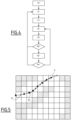
- FIG. 4 is a synopsis of the main steps of a second embodiment of the determination and storage of N-tuples of radio beacons for an air route defined by given turning points (or “waypoints”).
- no mesh of the terrain flown over by the air route is used.
- sequencing points of N-tuples of radio beacons are determined along a chosen air route R.
- An N-tuple of radio beacons is associated with a route segment between two sequencing points.
- the method according to this second embodiment comprises a first initialization step 70, comprising obtaining a list of coordinates of waypoints of the road R defined in a 2D or 3D reference frame and spaced by a step of advancement P along the road.
- the step of advancement P is a distance, preferably between 0.5 Nm and 2 Nm.
- the next step (step 72) is the search for an N-tuple at the current crossing point which allows the calculation of a protection radius lower than a threshold RNPMin, for example equal to 0.6Nm, or which provides the minimum value of the protection radius between 0.6Nm and 2Nm if it is not possible to find an N-tuple which gives a value lower than 0.6Nm.
- a threshold RNPMin for example equal to 0.6Nm
- step 74 of memorizing the N-tuple which gives the desired performance, for a trajectory segment having a first end equal to the current waypoint.
- This N-tuple becomes the current N-tuple.
- the current waypoint is a sequencing point of the N-tuples of the route.
- step P on the trajectory An advancement of one step P on the trajectory is made.
- the point on the trajectory becomes the current waypoint (step 76).
- next step 78 a search is carried out for DME radio beacons visible at the current waypoint.
- Step 80 is to determine whether the DME radio beacons of the current N-tuple are visible from the current waypoint.
- step 82 which consists of calculating the protection radius of the position calculated from the measurements provided by the DME radio beacons of the current N-tuple.
- the next step 84 consists of comparing the protection radius thus calculated with a predetermined maximum threshold value RNPmax, for example equal to 1.6Nm, and preferably between 1.6Nm and 2Nm.
- protection radius value is less than RNPMax, we start again at step 76, unless the current waypoint is the last point of the trajectory, in which case the process stops.
- step 84 is followed by step 72 previously described.
- N-tuple allowing to obtain a protection radius less than RNPMax is called a nominal N-tuple.
- the process is repeated for determine the selection to consider in degraded cases where one of the DME radio beacons provided in an N-uplet would not be available.
- the number of sequencing points with which N-tuples of radio beacons are associated is minimized.
- FIG. 5 schematically illustrates an air route R, waypoints W i defining this route and sequencing points PC i of N-tuples of radio beacons selected by implementing the method according to the second embodiment described above.
- the data associated with the selected N-tuples of radio beacons, for at least one given air route, according to the first or according to the second embodiment described above, are stored in a database 20 intended to be on board or made accessible for its use in an effective flight phase by an onboard aircraft navigation system.
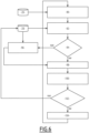
- FIG. 6 is a synopsis of the main steps of a first embodiment of a navigation method in the flight phase, using a database 20 in which data relating to N-tuples of radio beacons associated with meshes of a map are recorded.
- a two-dimensional mapping of the areas flown over by one or more air routes is used, as illustrated schematically in the Figure 2 .
- the steps are preferably implemented by executing a computer program by one or more processors of the on-board navigation system 10.
- a first step 90 the mesh associated with the current position of the aircraft, called the current mesh, is determined relative to a previous position of the aircraft. Initially, the current position of the aircraft is the position of the starting point of the air route to be followed.
- the determination of the mesh associated with the current position is done in relation to the latitude and longitude coordinates defining the meshes of the mapping recorded in the database 20.
- a step 92 of selecting a usable N-tuple of radio beacons is implemented.
- the N-tuples of radio beacons associated with the current mesh recorded in the database are considered in the order of increasing protection radii, and for each N-tuple, it is checked whether no radio beacon of the N-tuple has been marked as unusable. If all the radio beacons of the N-tuple considered are usable, this N-tuple is retained in step 92.
- this step is followed by a step 96 of implementing a conventional algorithm for selecting radio beacons, for example by searching for 3 DME beacons having a geometric configuration making it possible to maximize the minimum value of the angles of the triangle formed by these beacons.
- the N-tuple of radio beacons thus selected will be used during the step 98 described below.
- step 94 is followed by step 98 of adjusting the frequency channels of the on-board radio receiving devices according to the transmission frequencies of the radio beacons of the selected N-tuple.
- a reception of distance measurements ⁇ D 1 ...D N ⁇ and a consistency check is applied in step 100.
- each DME i radio beacon emits its identifier and information enabling the calculation of the distance between this beacon and a point on the aircraft or a distance measurement between the beacon and the aircraft.
- the consistency check implemented comprises comparing the received identifier with the identifier of the DME radio beacon i extracted from the database 20, and comparing (step 102) the distance measurement obtained with respect to a distance estimated using the previous spatial position.
- the DME radio beacon i is identified as unusable in the database 28 of radio beacons not to be used. In addition, the method returns to step 92 of selecting an N-tuple of usable radio beacons.
- step 102 is followed by a step 104 of calculating the integrated position, as well as the associated positioning accuracy performance level indicators. These are the precision (EPU) and integrity (HIL) indicators.
- the integrated position is provided as the new current position, and is also transmitted to the guidance system 30 for safe guidance of the aircraft.
- the algorithm for calculating the integrated position from the distance measurements D i received from DME radio beacons i is the same as that used during the preliminary phase of determining the N-tuples of radio beacons.
- an altitude estimate is used.
- FIG. 7 is a synopsis of the main steps of a second embodiment of a flight phase navigation method, using a database 20 in which data relating to a list of sequencing points of N-tuples of radio beacons to be used for the integrated position calculation along a chosen air route are recorded.
- the steps are preferably implemented by executing a computer program by one or more processors of the on-board navigation system 10.
- the method begins with an initialization step 110, of selecting the first sequencing point of the protected route having at least one N-tuple of associated radio beacons previously stored.
- an N-tuple of radio beacons associated with the current sequencing point is selected, for the segment of the route extending between the current sequencing point and the next sequencing point according to the current air route.
- This selection is the nominal N-tuple at the current point if none of the DME radio beacons in this list is indicated as unusable, or the alternative selection in the event of the presence of one or more unusable radio beacons in the nominal N-tuple.
- a step 114 of frequency adjustment (or “tuning” in English) on the radio communication frequency channels of the radio beacons of the selected N-tuple of radio beacons is implemented. Distance measurements are obtained.
- step 116 is carried out to calculate the integrated position (current position of the aircraft) based on the distance measurements obtained in the previous step.
- the calculation algorithm implements a consistency check similar to that described with reference to step 100.
- an alarm is raised (step 122) if it is not possible to determine the radio beacon which is the origin of the inconsistency (step 120).
- step 124 If the radio beacon causing the inconsistency is identified (response "yes" in step 120), it is checked in step 124 whether there is an alternative N-tuple associated with the current point and which does not contain the identified radio beacon. If there is such an N-tuple, step 124 is followed by step 112 previously described. Otherwise, step 124 is followed by step 122 for raising the alarm.
- the integrated position calculated in step 116 is provided as the new current position, and is also transmitted to the guidance system 30 for safe guidance of the aircraft.
- step 118 If no inconsistency is detected in step 118 for a duration greater than or equal to a given duration, it is followed by a step 126 of determining the distance from the current point to the next sequencing point.
- steps 116 to 126 are repeated.
- next sequencing point When the next sequencing point is reached (response "yes” in step 128), the method returns to step 112, the next sequencing point becomes the current sequencing point and a new N-tuple of radio beacons associated with the current sequencing point is selected. Steps 114 to 128 are repeated. If the next sequencing point reached is the last waypoint of the air route, the method ends (step 130).
Landscapes
- Engineering & Computer Science (AREA)
- Radar, Positioning & Navigation (AREA)
- Remote Sensing (AREA)
- Physics & Mathematics (AREA)
- General Physics & Mathematics (AREA)
- Computer Networks & Wireless Communication (AREA)
- Automation & Control Theory (AREA)
- Aviation & Aerospace Engineering (AREA)
- Position Fixing By Use Of Radio Waves (AREA)
- Traffic Control Systems (AREA)
- Navigation (AREA)
Claims (13)
- Navigationsverfahren eines Luftfahrzeugs entlang einer vorbestimmten Flugroute, das eine Positionierungsintegrität des Luftfahrzeugs während des Flugs in Bezug auf die Route bereitstellt, die ein erwartetes Leistungsniveau der Positionsgenauigkeit erfüllt, das Luftfahrzeug mindestens umfassend einen Funkempfänger an Bord, der angepasst ist, um mit mindestens einer terrestrischen Funkbake zu kommunizieren, die angepasst ist, um einen Abstand des Luftfahrzeugs in Bezug auf die Funkbake bereitzustellen,
umfassend bei seiner Durchführung in einer Navigationsphase des Luftfahrzeugs die folgenden Schritte:a) anhand einer aktuellen Position des Luftfahrzeugs, Erlangen (92, 112), anhand gespeicherter Daten (20), eines N-Tupels von zu verwendenden Funkbaken,b) Erlangen (98-100, 114) einer Abstandsmessung des Luftfahrzeugs von jeder der N Funkbaken des N-Tupels,c) Berechnen (104, 116) einer Integritätsposition mit einem probabilistischen Schutzradius um die berechnete Integritätsposition anhand der Abstandsmessungen, die durch ein vorbestimmtes Berechnungsverfahren erlangt werden,d) Verwenden der berechneten Integritätsposition als aktuelle Integritätsposition, um das Luftfahrzeug zu führen, dadurch gekennzeichnet, dass es eine vorherige Phase eines Bestimmens von N-Tupeln von Funkbaken umfasst, die von einer Rechenvorrichtung durchgeführt wird, die nicht an Bord des Luftfahrzeugs ist, umfassend Schritte, die, für mindestens ein Segment, das mit der Flugroute assoziiert ist, aus einem Bestimmen (60-68; 70-84) mindestens eines N-Tupels von Funkbaken, das unter Anwendung des Berechnungsverfahrens zum Berechnen einer Integritätsposition des Luftfahrzeugs beim Überfliegen eines mit dem Segment assoziierten Raumbereichs gemäß dem erwarteten Leistungsniveau der Positionierungsgenauigkeit verwendbar ist, und Speichern von Daten, die sich auf die bestimmten N-Tupel von Funkbaken beziehen, in einer Datenbank, bestehen. - Verfahren nach Anspruch 1, wobei jedes Segment der Route durch zwei Endpunkte, bezeichnet als Sequenzierungspunkte, definiert ist, die Bestimmung umfassend eine Bestimmung der Sequenzierungspunkte anhand von Wegpunkten, die die Flugroute definieren, wobei die Wegpunkte in einem vorbestimmten Vorwärtsbewegungsabstand beabstandet sind, wobei zwei aufeinanderfolgende Segmente entlang der Route unterschiedliche N-Tupel von assoziierten Funkbaken aufweisen.
- Verfahren nach Anspruch 1, wobei die überflogenen Raumbereiche auf einer Netzkartographie dargestellt sind, das Verfahren umfassend die folgenden Schritte:- Bestimmen (56) einer Folge von Netzen (50) der Kartografie, die von der genannten Flugroute überflogen werden,- Bestimmung (60, 62, 64), für jedes der Netze (50), von mindestens N-Tupel von Funkbaken, die es ermöglichen, eine Integritätsposition eines Luftfahrzeugs zu berechnen, das das Netz (50) der Kartografie überfliegt.
- Verfahren nach einem der Ansprüche 1 bis 3, wobei das Bestimmen eines N-Tupel von Funkbaken einen Test einer Vielzahl von N-Tupeln von Funkbaken umfasst jedes N-Tupel umfassend N Funkbaken, die ausgewählt sind aus einer Anzahl L größer als N Funkbaken, die sich in Empfangsreichweite eines Luftfahrzeugs befinden, das den Raumbereich überfliegt, der Test umfassend für jedes getestete N-Tupel von Funkbaken ein Erlangen von N Abstandsmessungen, wobei jede Abstandsmessung von einer der Funkbaken bereitgestellt wird, und eine Berechnen der Integritätsposition und eines assoziierten Integritätsradius, und ein Vergleichen des Integritätsradius mit einem Schwellenwert, der abhängig von dem erwarteten Leistungsniveau der Positionierungsgenauigkeit bestimmt wird.
- Verfahren nach einem der Ansprüche 1 bis 4, umfassend, in der Navigationsphase des Luftfahrzeugs bei dem Schritt a) eines Erlangens eines N-Tupel von Funkbaken, ein Auswählen (92) eines N-Tupel von Funkbaken und ein Überprüfen (94) der Verfügbarkeit von jedem der Funkbaken des ausgewählten N-Tupels von Funkbaken und im Fall einer Nichtverfügbarkeit ein Auswählen eines anderen N-Tupel von Funkbaken aus der gespeicherten Datenbasis.
- Verfahren nach einem der Ansprüche 3 oder 4, umfassend, in der Navigationsphase des Luftfahrzeugs, ein Bestimmen (90), anhand der aktuellen Position des Luftfahrzeugs, eines entsprechenden Kartierungsnetzes und ein Erlangen eines N-Tupels von Funkbaken, die mit dem bestimmten entsprechenden Netz assoziiert sind.
- Verfahren nach Anspruch 2, umfassend, in der Navigationsphase des Luftfahrzeugs, ein Bestimmen, anhand einer aktuellen Position des Luftfahrzeugs, die mit einem aktuellen Sequenzierungspunkt assoziiert ist, eine Auswahl (112) eines N-Tupels von gespeicherten Funkbaken in Assoziierung mit einem Segment, das durch den aktuellen Sequenzierungspunkt und einen nächsten Sequenzierungspunkt entlang der Flugroute des Luftfahrzeugs definiert ist.
- Verfahren nach Anspruch 7, umfassend ein Überprüfen (128) des Erreichens des nächsten Sequenzierungspunkts durch das Luftfahrzeug, und ein Erlangen eines neuen N-Tupels von Funkbaken, die infolge eines Überschreitens des nächsten Sequenzierungspunkts zu verwenden sind.
- Verfahren nach einem der Ansprüche 1 bis 8, ferner umfassend, nach dem Schritt b) eines Erlangens von Abstandsmessungen ein Kohärenzüberprüfen (100-102; 118-120) der erlangten Abstandsmessungen und im Fall einer Inkonsistenz ein Bestimmen einer Funkbake, die eine inkonsistente Abstandsmessung bereitstellt, und im Fall einer erfolgreichen Bestimmung ein Speichern einer Kennung der oder jeder Funkbake, die eine inkonsistente Messung bereitstellt, in einer Datenbank für nicht verwendbare Funkbaken.
- Verfahren nach Anspruch 9, ferner umfassend eine Alarmerhebung (122) bei Feststellung einer Inkonsistenz.
- Verfahren nach einem der Ansprüche 1 bis 10, umfassend, vor dem Erlangen einer Abstandsmessung eine Einstellung (98; 114) von mindestens einem Funkempfänger an Bord auf eine Sendefrequenz einer Funkbake des N-Tupels.
- Computerprogramm, umfassend Softwareanweisungen, die, wenn sie von einer elektronischen Rechenvorrichtung durchgeführt werden, ein Navigationsverfahren nach den Ansprüchen 1 bis 11 durchführen.
- System (2) zur Navigation eines Luftfahrzeugs entlang einer vorbestimmten Flugroute, umfassend ein Bordnavigationssystem (4) an Bord und umfassend eine elektronische Rechenvorrichtung, umfassend mindestens einen Prozessor (12) und eine Speichereinheit (14) umfasst, die eine Positionierungsintegrität des Luftfahrzeugs während des Flugs in Bezug auf die Route bereitstellt, die ein Leistungsniveau der erwarteten Positionierungsgenauigkeit einhält, und mindestens einen Funkempfänger (24) an Bord des Luftfahrzeugs, der angepasst ist, um mit mindestens einer terrestrischen Funkbake zu kommunizieren, die angepasst ist, um einen Abstand des Luftfahrzeugs in Bezug auf die Funkbake bereitzustellen,
das System (2) umfassend Module, die in der Navigationsphase des Luftfahrzeugs durchgeführt werden, umfassend:- ein Modul (18), das konfiguriert ist, um anhand einer aktuellen Position des Luftfahrzeugs anhand von Daten (20, 28), die in der Speichereinheit (14) gespeichert sind, ein N-Tupel von zu verwendenden Funkbaken zu erlangen,- ein Modul (22), das konfiguriert ist, um durch mindestens einen der Bordempfänger eine Abstandsmessung des Luftfahrzeugs zu jedem der N Funkbaken des N-Tupels zu erlangen,- ein Modul (26), das konfiguriert ist, um anhand der Abstandsmessungen, die durch ein vorbestimmtes Berechnungsverfahren erlangt werden, eine Integritätsposition mit einem probabilistischen Schutzradius um die berechnete Integritätsposition zu berechnen, und- ein Modul (30), das konfiguriert ist, um die berechnete Integritätsposition als aktuelle Integritätsposition zu verwenden, dadurch gekennzeichnet, dass das System ferner ein nicht an Bord befindliches System (6) umfasst, das angepasst ist, um eine vorherige Navigationsdaten-Vorbereitungsphase durchzuführen, umfassend eine elektronische Rechenvorrichtung (40), die angepasst ist, um ein Modul (46) zur Bestimmung von N-Tupeln von Funkbaken durchzuführen, das konfiguriert ist, um für mindestens ein Segment, das mit der Flugroute assoziiert ist, mindestens ein N-Tupel von Funkbaken zu bestimmen (60-68; 70-84), das unter Anwendung des Berechnungsverfahrens zum Berechnen einer Integritätsposition des Luftfahrzeugs beim Überfliegen eines mit dem Segment assoziierten Raumbereichs gemäß dem erwarteten Leistungsniveau der Positionierungsgenauigkeit verwendbar ist, und Speichern von Daten, die sich auf die bestimmten N-Tupel von Funkbaken beziehen, in einer Datenbank.
Applications Claiming Priority (1)
| Application Number | Priority Date | Filing Date | Title |
|---|---|---|---|
| FR1871548A FR3088443B1 (fr) | 2018-11-13 | 2018-11-13 | procédé et système de navigation d'aéronef |
Publications (3)
| Publication Number | Publication Date |
|---|---|
| EP3657210A1 EP3657210A1 (de) | 2020-05-27 |
| EP3657210B1 true EP3657210B1 (de) | 2025-06-04 |
| EP3657210C0 EP3657210C0 (de) | 2025-06-04 |
Family
ID=66776395
Family Applications (1)
| Application Number | Title | Priority Date | Filing Date |
|---|---|---|---|
| EP19208550.4A Active EP3657210B1 (de) | 2018-11-13 | 2019-11-12 | Navigationsverfahren und -system eines luftfahrzeugs |
Country Status (4)
| Country | Link |
|---|---|
| US (1) | US11385073B2 (de) |
| EP (1) | EP3657210B1 (de) |
| CN (1) | CN111174789B (de) |
| FR (1) | FR3088443B1 (de) |
Families Citing this family (4)
| Publication number | Priority date | Publication date | Assignee | Title |
|---|---|---|---|---|
| FR3115871B1 (fr) | 2020-10-29 | 2022-12-23 | Thales Sa | Navigation rnp sans gnss |
| FR3127279B1 (fr) * | 2021-09-21 | 2023-09-15 | Airbus Sas | Procédé de détermination d’une caractéristique associée à une portion de trajectoire d’un aéronef. |
| CN114275160B (zh) * | 2021-12-28 | 2022-08-23 | 中国科学院空天信息创新研究院 | 一种具有多维度信息探测能力的航空平台及协同作业方法 |
| FR3166981A1 (fr) | 2024-10-01 | 2026-04-03 | Thales | Procédé et dispositif électronique de détermination de balises de radionavigation pour un aéronef, programme d'ordinateur, procédé de navigation et système électronique de navigation associés |
Family Cites Families (21)
| Publication number | Priority date | Publication date | Assignee | Title |
|---|---|---|---|---|
| US3936828A (en) * | 1972-12-22 | 1976-02-03 | Communications Components Corporation | VLF navigation system |
| US5923286A (en) * | 1996-10-23 | 1999-07-13 | Honeywell Inc. | GPS/IRS global position determination method and apparatus with integrity loss provisions |
| US6112141A (en) * | 1997-10-15 | 2000-08-29 | Dassault Aviation | Apparatus and method for graphically oriented aircraft display and control |
| FR2829100B1 (fr) * | 2001-08-30 | 2005-10-21 | Marcel Bruno | Procede, dispositif et balise de localisation de sinistre pour former un appareillage de sauvetage en mer |
| US7298314B2 (en) * | 2002-08-19 | 2007-11-20 | Q-Track Corporation | Near field electromagnetic positioning system and method |
| US7751829B2 (en) * | 2003-09-22 | 2010-07-06 | Fujitsu Limited | Method and apparatus for location determination using mini-beacons |
| FR2893144B1 (fr) * | 2005-11-04 | 2007-12-21 | Thales Sa | Procede de selection automatique de balises de radionavigation |
| US9857476B2 (en) * | 2006-04-28 | 2018-01-02 | Telecommuncation Systems, Inc. | GNSS long-code acquisition, ambiguity resolution, and signal validation |
| FR2910616B1 (fr) * | 2006-12-22 | 2009-09-11 | Thales Sa | Dispositif et procede d'assistance au choix d'aeroports de deroutement |
| US7564404B2 (en) * | 2007-08-10 | 2009-07-21 | Daniel A. Katz | Determining precise direction and distance to a satellite radio beacon |
| CA2617976A1 (en) * | 2008-01-11 | 2009-07-11 | John Dasilva | Personnel safety system utilizing time variable frequencies |
| KR101868819B1 (ko) * | 2010-06-11 | 2018-06-19 | 스카이후크 와이어리스, 인크. | 무선 액세스 포인트의 비콘 안정도를 측정하기 위한 방법 및 시스템 |
| FR2964468B1 (fr) * | 2010-09-08 | 2012-09-28 | Sagem Defense Securite | Procede et dispositif de detection et d'exclusion de pannes satellite multiples dans un systeme gnss |
| FR2966606B1 (fr) * | 2010-10-22 | 2012-11-02 | Thales Sa | Procede et systeme de geo-localisation d'une radio-balise dans un systeme d'alerte. |
| FR2982062B1 (fr) * | 2011-10-27 | 2013-12-13 | Airbus Operations Sas | Procede et un dispositif d'aide a la garantie de la precision et de l'integrite d'une position d'un aeronef au sol. |
| FR3030057B1 (fr) * | 2014-12-12 | 2017-01-27 | Thales Sa | Procede et systeme de validation de geolocalisation par satellite |
| GB2558851B (en) * | 2015-11-13 | 2018-10-31 | Walmart Apollo Llc | Product delivery methods and systems utilizing portable unmanned delivery aircraft |
| CN105651277B (zh) * | 2016-01-06 | 2018-08-14 | 中国航空无线电电子研究所 | 一种用于选择区域导航所需陆基导航台的方法 |
| AU2017268026B2 (en) * | 2016-05-20 | 2022-08-04 | Myriota Pty Ltd | Position estimation in a low earth orbit satellite communications system |
| FR3053779B1 (fr) * | 2016-07-07 | 2018-06-29 | Thales | Dispositif et methode de calcul de prediction de performance de navigation estimee |
| BR112020003051A2 (pt) * | 2017-08-14 | 2020-08-25 | American Robotics, Inc. | métodos e sistemas para melhorar a precisão de pousos autônomos por aeronave drone em alvos de pouso |
-
2018
- 2018-11-13 FR FR1871548A patent/FR3088443B1/fr active Active
-
2019
- 2019-11-06 US US16/675,726 patent/US11385073B2/en active Active
- 2019-11-08 CN CN201911086658.8A patent/CN111174789B/zh active Active
- 2019-11-12 EP EP19208550.4A patent/EP3657210B1/de active Active
Also Published As
| Publication number | Publication date |
|---|---|
| US20200149922A1 (en) | 2020-05-14 |
| US11385073B2 (en) | 2022-07-12 |
| FR3088443A1 (fr) | 2020-05-15 |
| CN111174789B (zh) | 2024-05-10 |
| FR3088443B1 (fr) | 2022-03-11 |
| EP3657210C0 (de) | 2025-06-04 |
| CN111174789A (zh) | 2020-05-19 |
| EP3657210A1 (de) | 2020-05-27 |
Similar Documents
| Publication | Publication Date | Title |
|---|---|---|
| EP3657210B1 (de) | Navigationsverfahren und -system eines luftfahrzeugs | |
| EP3267156B1 (de) | Vorrichtung und methode zur berechnung der vorhersage einer geschätzten navigationsleistung | |
| EP2573586A1 (de) | Verfahren und System zur Steuerung eines Luftfahrzeugs in der Anflugphase auf eine Landebahn | |
| FR2928741A1 (fr) | Dispositif et procede de surveillance d'integrite en temps reel d'un systeme de navigation par satellite | |
| JP6664318B2 (ja) | リスク推定システム、およびリスク推定方法 | |
| EP1466139B1 (de) | Hybride trägheitsnavigationszentrale mit verbesserter höhenintegrität | |
| FR3006049A1 (fr) | Procede et systeme de selection d'une trajectoire d'approche | |
| FR3008818A1 (fr) | Dispositif et procede de prediction au sol de la precision, l'integrite et la disponibilite de la position d'un aeronef le long d'une trajectoire. | |
| FR3023922A1 (fr) | Recepteur de positionnement et de navigation a indicateur de confiance | |
| FR2622301A1 (fr) | Systeme anticollision pour avions et autres moyens de transport, procede et appareil pour son application | |
| WO2014170478A1 (fr) | Procede de controle d'integrite et dispositif de fusion-consolidation comprenant une pluralite de modules de traitement | |
| EP3346282A1 (de) | Elektronische vorrichtung zur überwachung mindestens eines satellitennavigationssignals in der annäherungsphase an eine landebahn, entsprechendes überwachungsverfahren und entsprechendes computerprogramm | |
| WO2022219007A1 (fr) | Adaptation automatique du profil vertical d'un aeronef en fonction d'une incertitude de position | |
| EP2366094B1 (de) | Verfahren mit druckhöhenkorrektur für ein flugzeug | |
| FR2962838A1 (fr) | Procede d'aide au pilotage ameliore pour aeronef | |
| EP2367025B1 (de) | Prüfungsverfahren und -system der Präzisionsleistungen eines satellitengesteuerten Navigationssystems | |
| FR2904706A1 (fr) | Procede et dispositif pour determiner une hauteur de decision lors d'une approche autonome d'un aeronef. | |
| EP2367024B1 (de) | Berechnungsverfahren und -system zur Einschätzung der Präzisionsleistung eines satellitengesteuerten Navigationssystems | |
| EP1956386A1 (de) | Verfahren zur Positionsbestimmung eines mobilen Körpers und einer Schutzgrenze um diese Position | |
| FR3027410A1 (fr) | Detection de perturbation d'un message de correction differentielle de mesure de positionnement d'un dispositif de geolocalisation par satellite | |
| WO2022152723A1 (fr) | Dispositif électronique de stockage d'une base de données terrain, procédé de génération d'une telle base de données, système avionique, procédé de surveillance et programmes d'ordinateur associés | |
| EP3770626A1 (de) | Verfahren zur validierung mindestens einer vorbestimmten positionsdateninformation, die in einer datenbank eines luftfahrzeugs gespeichert ist, entsprechendes computerprogramm und entsprechende vorrichtung | |
| EP4237796B1 (de) | Rnp-navigation ohne gnss | |
| JP6803748B2 (ja) | 情報処理システム、および情報処理方法 | |
| FR3020170A1 (fr) | Procede de guidage d'un aeronef |
Legal Events
| Date | Code | Title | Description |
|---|---|---|---|
| PUAI | Public reference made under article 153(3) epc to a published international application that has entered the european phase |
Free format text: ORIGINAL CODE: 0009012 |
|
| STAA | Information on the status of an ep patent application or granted ep patent |
Free format text: STATUS: THE APPLICATION HAS BEEN PUBLISHED |
|
| AK | Designated contracting states |
Kind code of ref document: A1 Designated state(s): AL AT BE BG CH CY CZ DE DK EE ES FI FR GB GR HR HU IE IS IT LI LT LU LV MC MK MT NL NO PL PT RO RS SE SI SK SM TR |
|
| AX | Request for extension of the european patent |
Extension state: BA ME |
|
| STAA | Information on the status of an ep patent application or granted ep patent |
Free format text: STATUS: REQUEST FOR EXAMINATION WAS MADE |
|
| 17P | Request for examination filed |
Effective date: 20201027 |
|
| RBV | Designated contracting states (corrected) |
Designated state(s): AL AT BE BG CH CY CZ DE DK EE ES FI FR GB GR HR HU IE IS IT LI LT LU LV MC MK MT NL NO PL PT RO RS SE SI SK SM TR |
|
| STAA | Information on the status of an ep patent application or granted ep patent |
Free format text: STATUS: EXAMINATION IS IN PROGRESS |
|
| 17Q | First examination report despatched |
Effective date: 20221024 |
|
| P01 | Opt-out of the competence of the unified patent court (upc) registered |
Effective date: 20230425 |
|
| REG | Reference to a national code |
Ref legal event code: R079 Ipc: G01S0005000000 Ref country code: DE Ref legal event code: R079 Ref document number: 602019070697 Country of ref document: DE Free format text: PREVIOUS MAIN CLASS: G01S0013780000 Ipc: G01S0005000000 |
|
| GRAP | Despatch of communication of intention to grant a patent |
Free format text: ORIGINAL CODE: EPIDOSNIGR1 |
|
| STAA | Information on the status of an ep patent application or granted ep patent |
Free format text: STATUS: GRANT OF PATENT IS INTENDED |
|
| RIC1 | Information provided on ipc code assigned before grant |
Ipc: G01S 13/78 20060101ALI20250227BHEP Ipc: G01S 19/48 20100101ALI20250227BHEP Ipc: G01S 5/00 20060101AFI20250227BHEP |
|
| INTG | Intention to grant announced |
Effective date: 20250320 |
|
| GRAS | Grant fee paid |
Free format text: ORIGINAL CODE: EPIDOSNIGR3 |
|
| GRAA | (expected) grant |
Free format text: ORIGINAL CODE: 0009210 |
|
| STAA | Information on the status of an ep patent application or granted ep patent |
Free format text: STATUS: THE PATENT HAS BEEN GRANTED |
|
| AK | Designated contracting states |
Kind code of ref document: B1 Designated state(s): AL AT BE BG CH CY CZ DE DK EE ES FI FR GB GR HR HU IE IS IT LI LT LU LV MC MK MT NL NO PL PT RO RS SE SI SK SM TR |
|
| REG | Reference to a national code |
Ref country code: GB Ref legal event code: FG4D Free format text: NOT ENGLISH |
|
| REG | Reference to a national code |
Ref country code: CH Ref legal event code: EP |
|
| REG | Reference to a national code |
Ref country code: DE Ref legal event code: R096 Ref document number: 602019070697 Country of ref document: DE |
|
| REG | Reference to a national code |
Ref country code: IE Ref legal event code: FG4D Free format text: LANGUAGE OF EP DOCUMENT: FRENCH |
|
| U01 | Request for unitary effect filed |
Effective date: 20250605 |
|
| P04 | Withdrawal of opt-out of the competence of the unified patent court (upc) registered |
Free format text: CASE NUMBER: APP_27729/2025 Effective date: 20250610 |
|
| U07 | Unitary effect registered |
Designated state(s): AT BE BG DE DK EE FI FR IT LT LU LV MT NL PT RO SE SI Effective date: 20250613 |
|
| PG25 | Lapsed in a contracting state [announced via postgrant information from national office to epo] |
Ref country code: ES Free format text: LAPSE BECAUSE OF FAILURE TO SUBMIT A TRANSLATION OF THE DESCRIPTION OR TO PAY THE FEE WITHIN THE PRESCRIBED TIME-LIMIT Effective date: 20250604 |
|
| PG25 | Lapsed in a contracting state [announced via postgrant information from national office to epo] |
Ref country code: NO Free format text: LAPSE BECAUSE OF FAILURE TO SUBMIT A TRANSLATION OF THE DESCRIPTION OR TO PAY THE FEE WITHIN THE PRESCRIBED TIME-LIMIT Effective date: 20250904 Ref country code: GR Free format text: LAPSE BECAUSE OF FAILURE TO SUBMIT A TRANSLATION OF THE DESCRIPTION OR TO PAY THE FEE WITHIN THE PRESCRIBED TIME-LIMIT Effective date: 20250905 |
|
| PG25 | Lapsed in a contracting state [announced via postgrant information from national office to epo] |
Ref country code: PL Free format text: LAPSE BECAUSE OF FAILURE TO SUBMIT A TRANSLATION OF THE DESCRIPTION OR TO PAY THE FEE WITHIN THE PRESCRIBED TIME-LIMIT Effective date: 20250604 |
|
| PG25 | Lapsed in a contracting state [announced via postgrant information from national office to epo] |
Ref country code: HR Free format text: LAPSE BECAUSE OF FAILURE TO SUBMIT A TRANSLATION OF THE DESCRIPTION OR TO PAY THE FEE WITHIN THE PRESCRIBED TIME-LIMIT Effective date: 20250604 |
|
| PG25 | Lapsed in a contracting state [announced via postgrant information from national office to epo] |
Ref country code: RS Free format text: LAPSE BECAUSE OF FAILURE TO SUBMIT A TRANSLATION OF THE DESCRIPTION OR TO PAY THE FEE WITHIN THE PRESCRIBED TIME-LIMIT Effective date: 20250904 |
|
| U20 | Renewal fee for the european patent with unitary effect paid |
Year of fee payment: 7 Effective date: 20251028 |
|
| PG25 | Lapsed in a contracting state [announced via postgrant information from national office to epo] |
Ref country code: IS Free format text: LAPSE BECAUSE OF FAILURE TO SUBMIT A TRANSLATION OF THE DESCRIPTION OR TO PAY THE FEE WITHIN THE PRESCRIBED TIME-LIMIT Effective date: 20251004 |
|
| PGFP | Annual fee paid to national office [announced via postgrant information from national office to epo] |
Ref country code: GB Payment date: 20251126 Year of fee payment: 7 |
|
| PG25 | Lapsed in a contracting state [announced via postgrant information from national office to epo] |
Ref country code: SM Free format text: LAPSE BECAUSE OF FAILURE TO SUBMIT A TRANSLATION OF THE DESCRIPTION OR TO PAY THE FEE WITHIN THE PRESCRIBED TIME-LIMIT Effective date: 20250604 |
|
| PG25 | Lapsed in a contracting state [announced via postgrant information from national office to epo] |
Ref country code: CZ Free format text: LAPSE BECAUSE OF FAILURE TO SUBMIT A TRANSLATION OF THE DESCRIPTION OR TO PAY THE FEE WITHIN THE PRESCRIBED TIME-LIMIT Effective date: 20250604 |
|
| PG25 | Lapsed in a contracting state [announced via postgrant information from national office to epo] |
Ref country code: SK Free format text: LAPSE BECAUSE OF FAILURE TO SUBMIT A TRANSLATION OF THE DESCRIPTION OR TO PAY THE FEE WITHIN THE PRESCRIBED TIME-LIMIT Effective date: 20250604 |
|
| PLBE | No opposition filed within time limit |
Free format text: ORIGINAL CODE: 0009261 |
|
| STAA | Information on the status of an ep patent application or granted ep patent |
Free format text: STATUS: NO OPPOSITION FILED WITHIN TIME LIMIT |
|
| REG | Reference to a national code |
Ref country code: CH Ref legal event code: L10 Free format text: ST27 STATUS EVENT CODE: U-0-0-L10-L00 (AS PROVIDED BY THE NATIONAL OFFICE) Effective date: 20260416 |